Table of Contents
Advertisement
Available languages
Available languages
Quick Links
Advertisement
Chapters
Table of Contents

Related Manuals for Otto Bock E-MAG Active 17B202N


Summary of Contents for Otto Bock E-MAG Active 17B202N
- Page 1 17B202N E-MAG Active Einbau- und Service-Anleitung �����������������������������������������������������3 E-MAG Active mounting and service instructions ���������������������������������������������� 38...
-
Page 3: Table Of Contents
Einbau- und Serviceanleitung für das E-MAG Active Kniegelenksystem INFORMATION Bevor Sie dem Patienten die Einbau- und Serviceanleitung übergeben, müssen Sie den Patienten mit der Bedienung vertraut machen! Inhalt Seite 1 Einleitung .........................5 1.1 Vorwort ........................5 1.2 Verwendungszweck ....................5 1.3 Patientenauswahl ....................5 1.4 Indikation ........................6 1.5 Kontraindikation .....................6 1.6 Funktion und Konstruktion ..................7... - Page 4 4.1.10 Alarmkonfiguration ..................30 4.1.11 Akkumulator (Abb. 58)................31 4.1.12 Ladegerät (Abb. 59) ..................31 5 Wartungshinweise ......................32 5.1 Funktions- und Verschleißkontrolle ..............33 5.2 Störungen oder Defekte an den elektronischen Teilen ........35 5.2.1 System startet nicht vollständig ..............35 5.2.2 Störung der Elektronik ................35 5.2.3 Sperre schließt nicht ...................35 5.3 Wartungsplan .......................36 6 Technische Daten ......................37...
-
Page 5: Einleitung
Das System kann in verschiedene Arten von Orthesentechniken eingebaut werden. Wir empfehlen die Gießharz- oder Prepreg-Technik. Das E-MAG Kniegelenksystem E-MAG Active 17B202N=* wird Ihnen als Komplettsystem ge- liefert. Alle funktionsrelevanten Teile sind enthalten. Systemschienen und der mediale Mitläufer sind nicht enthalten. Bitte lesen Sie dazu auch das Kapitel 1.6.4, Zubehör. -
Page 6: Patientenauswahl
1.3 Patientenauswahl Bilateraler Einsatz mit Mitläufer 17B205=* Unilateraler Einsatz Maximales Patientengewicht: ≤ 100 kg Maximales Patientengewicht: ≤ 85 kg Kontraindikationen Kontraindikationen • unkontrollierbare Spastiken • unkontrollierbare Spastiken • Tuberanstützungen • Tuberanstützungen • Beugekontrakturen über 15° • unphysiologische Abweichungen in Frontalebene (siehe Abb. 1) •... -
Page 7: Funktion Und Konstruktion
Ausschlaggebend sind die körperlichen Voraussetzungen, wie Muskelstatus, Bewegungsgrade oder Achsabweichungen, die ein sicheres Steuern der Orthese gewährleisten müssen. Weitere Indikationen und die Auswahl des passenden Systems für Ihren Patienten hängen vor- wiegend von den vorhandenen Muskelkräften, Gelenkmobilitäten und Achsabweichungen ab, die insgesamt die Eignung des Patienten für das eine oder andere Gelenksystem bestimmen. -
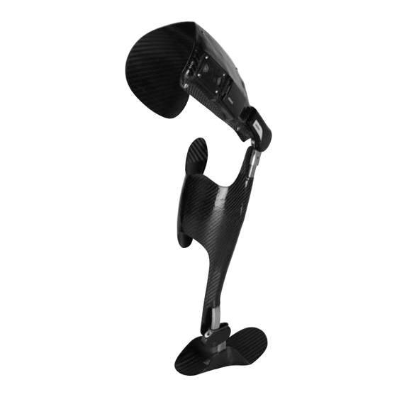
Page 8: Elektronische Komponenten (Abb. 3)
1.6.3 Elektronische Komponenten (Abb. 3) A Elektronik / Einlegerahmen-Set (317B3/317Z13) B Akku / Einlegerahmen-Set (317B20/317Z21) C Ladegerät (317L20) D Dummy für Akkumulator-Einlegerahmen (30Y103) E Dummy für Elektronik-Einlegerahmen (30Y100) F Dummy für Elektronik (30Y123) G Dummy für Akku (30Y124) H Akkukabel und Rasteinheit (317E20) I Elektronikkabel (317E2) 1.6.4 Zubehör... -
Page 9: Konstruktion
Medialer Mitläufer 17B205=* in links oder Flexionsunterteile E-MAG Active (in 5°, 7.5° rechts – Stahl und 10°) Schienensystem für Mitläufer 605P8=*, Leicht- metall in den Abmessungen 5x20x2000mm und 5x20x305mm (Dicke x Breite x Länge) INFORMATION Der Umbau der Flexionsunterteile auf 7,5° bzw.10° ist nur durch eine Ottobock Serviceeinrichtung durchzuführen. -
Page 10: Sicherheitshinweise
2 Sicherheitshinweise 2.1 Bedeutung der Symbolik Warnungen vor möglichen Unfall- und Verletzungsgefahren. VORSICHT Warnungen vor möglichen technischen Schäden. HINWEIS Hinweise zur Bedienung. Hinweise für das Service-Personal. INFORMATION 2.2 Allgemeine Sicherheitshinweise INFORMATION Eine Zertifizierung für das E-MAG Active ist obligatorisch. Ohne namentlich zertifizierten Orthopädie- Techniker ist das E-MAG Active nicht CE-konform und somit verfällt die CE-Kennzeichnung aus indus- trieller Sicht. - Page 11 VORSICHT Quetschgefahr. Achten Sie auf eine freie Bewegung in der Beuge. Lassen Sie keine Überlappungen von Schäften zu. Das Kniegelenk hat einen max. Beugewinkel von 150°. VORSICHT Sturzgefahr durch falsche Kalibrierung. Gehen Sie bei der Autokalibrierung nach den vorgegebenen Schritten vor, damit es nicht zu einem ungewollten Auslösen des Gelenks kommt. VORSICHT Sturzgefahr durch unzulässige Bedienung der Serviceknöpfe.
-
Page 12: Einbauanleitung
Orthese gewährleistet ist. INFORMATION Das Gelenk darf im Bereich der Lagerung gewartet und repariert werden. Reparaturen am Sperrme- chanismus dürfen nur durch eine Otto Bock Serviceeinrichtung vorgenommen werden. 3 Einbauanleitung Dieses Kapitel beschreibt die erforderlichen Arbeitsschritte zum Einbau des E-MAG Kniegelenksy- stems in eine Gesamtorthese und zur Herstellung einer Verkleidungsschale, mit der die Elektronik, Kabel und das Akkugehäuse am Oberschaft fixiert und vor äußeren Einflüssen geschützt werden. - Page 13 3.1 Einbau des E-MAG Kniegelenksystems INFORMATION Das Gelenk kann in verschiedene Arten von Orthesentechniken eingebaut werden. Wir empfehlen die Gießharz- oder Prepreg-Technik. Modellieren Sie zunächst das Gipspositiv wie gewohnt. Positionieren Sie den Dummy A für das Kniegelenk B (Abb. 8) mit Hilfe des Justiersatzes 743R6 direkt auf dem Kompromissdrehpunkt nach Nietert (Abb.
- Page 14 Beachten Sie bei der Anordnung der Bauteile die Länge der Kabel: • Akku – Elektronik: 50 cm, variable Länge • Elektronik – Kniegelenk: 30 cm, feste Länge HINWEIS Beschädigung des Kabels. Eine Durchtrennung zerstört das Kabel zwischen Kniegelenk und Elektronik. Das Kabel zwischen Kniegelenk und Elektronik darf weder gekürzt noch verlängert werden.
- Page 15 Zeichnen Sie anschließend die Kontur der Verkleidungsschale (Abb. 15) und die Position der Eingussplättchen (Abb. 16) für die spätere Verschraubung der Schale auf dem Oberschaft ein. VORSICHT Verletzungsgefahr bei Schienenbruch. Schienenbruch an der Orthese kann zu Verletzungen des Patienten führen. Beschleifen und glätten Sie Risse und Grate an den Schienen sorgfältig, bevor Sie die Orthese gießen.
- Page 16 INFORMATION Die Verkleidungsschale dient ausschließlich dem Schutz und der Fixierung von Akku, Elektronik und Kabelverbindungen. Es reicht aus, wenn ihre Fläche diese Komponenten ausreichend umschließt. Berücksichtigen Sie jedoch individuelle Patientenwünsche: Soll ein Polster am Oberschaft angebracht werden, empfiehlt es sich, die Verkleidungsschale so groß zu gestalten, dass Sie darauf das Polster kleben können.
-
Page 17: Verkleidungsschale
3.2 Verkleidungsschale In diesem Abschnitt erfahren Sie, wie Sie eine Verkleidungsschale zum Schutz und zur Fixierung von Kabeln und Elektronikbauteilen herstellen. INFORMATION Markierte Schalenauflage ist für die Stabilität notwendig (siehe auch Abb. 22/23). Schneiden Sie zunächst den Kniegelenkdummy frei, wie in Abb. 21 skizziert. Entfernen Sie den Kniegelenkdummy. - Page 18 VORSICHT Beschädigung durch Einbaufehler. Bitte beachten Sie, dass beim Auffräsen keine Kerben im Schie- nenmaterial entstehen, da hierdurch Sollbruchstellen entstehen. Messen Sie die Länge der beiliegenden Kabeldummys: • Dummy für das Kabel zwischen Kniegelenk und Elektronik (7 mm breit, Abb. 24), •...
- Page 19 Nehmen Sie das Vulkolanband ab und fixieren Sie die Dummys für Akku mit Einlegerahmen und Elektronik mit Einlegerahmen mit doppelseitigem Klebeband. Füllen Sie nun die Kanten zwischen Dummys und Schaft mit Plastilin auf, um einen gleichmäßigen Übergang zu erzielen (Abb. 28). Ziehen Sie eine Lage Nylonstrumpf 99B25 über die fertige Orthese auf dem Gipsmodell.
- Page 20 indem Sie diese bis auf eine Umdrehung vor Anschlag hineindrehen. Erwärmen Sie jetzt das umgebende Laminat kurz mit der Düse eines Heißluftföhns (Abb. 32). Sobald sich Blasen auf der PVA-Folie bilden, drehen Sie die Schrauben ganz hinein. Der Schraubenkopf ist jetzt versenkt. Bevor Sie die Schale und die Orthese abnehmen, schleifen Sie zunächst vorsichtig die Dummys bis zu den Kanten plan frei (Abb.
- Page 21 Fixieren Sie die Einheit von außen mit PVC-Klebeband. Ziehen Sie das Klebeband straff, um einen möglichst dichten Abschluss zu erreichen. HINWEIS Beschädigung des Einlegerahmens. Siegelharz im Inneren kann den Einlegerahmen zerstören. Harz löst das Material des Einlegerahmens an. Lassen Sie deshalb kein Harz in das Innere des Ein- legerahmens laufen.
-
Page 22: Endmontage
Stellen Sie die Orthese wie gewohnt fertig: Montieren Sie das Knie- und ggf. das Knöchelgelenk und bringen Sie Innenpolster und Verschlüsse an. 3.3 Endmontage Entfernen Sie die Dummys für Elektronik und Akku aus den Einlegerahmen. HINWEIS Kurzschlussgefahr. Legen Sie den Akku erst ein, wenn das gesamte System montiert ist. Schließen Sie zunächst beide Kabel an den Einlegerahmen für die Elektronik an (Abb. - Page 23 INFORMATION Bitte beachten Sie, dass nach einer Kürzung der volle Querschnitt der Kabel erhalten bleibt. rot gekennzeichnet rot markiert rot gekennzeichnet rot gekennzeichnet rot gekennzeichnet rot gekennzeichnet rot markiert rot markiert rot gekennzeichnet rot gekennzeichnet INFORMATION Das E-MAG Kniegelenk ist mit einem Verpolungsschutz ausgestattet: Bei falscher Polung wird ein Kurzschluss verhindert, indem die Elektronik abgeschaltet wird.
- Page 24 Elektronische Verbindungen können oxidieren. Schützen Sie Kontakte und Kabelübergänge mit Silikonfett 633F11, wie in Abb. 48 angegeben. Setzen Sie die Elektronik in den Einlegerahmen (Abb. 49) ein und fixieren Sie sie mit den beige- fügten Schrauben (Abb. 50) mit max. 1 Nm. Bitte beachten Sie die genaue Positionierung der Elektronik und des Einlegerahmens (Siehe Abb.
- Page 25 VORSICHT Verletzungsgefahr durch falsch verklebte Systemschienen. Lösen sich Schienen aus Gelenkverbin- dungen, kann der Patient stürzen und sich verletzen. Verkleben Sie deshalb vor der Auslieferung der Orthese alle Systemschienen mit dem Klebemittel 636W28. Rauen Sie die Schienen auf und entfetten Sie sie vor dem Einkleben.
-
Page 26: Arbeitshinweise Elektronische Komponenten
Schrauben Sie die Schale auf den Oberschaft. Legen Sie abschließend den Akku ein und überprüfen Sie alle Funktionen. Übergeben Sie dem Anwender die Bedienungsanleitung und den Quickstart und erklären Sie ihm bei Auslieferung die Funktionen des E-MAG Kniegelenks. Weisen Sie ihn auf die halbjähr- lichen Wartungsintervalle hin. -
Page 27: Power On Selbsttest - Erstes Einlegen Des Akkus
4.1.1 Power on Selbsttest – erstes Einlegen des Akkus Nach fertiger Verkabelung kann der Akku für das erste Einschalten des E-MAG Active eingesetzt werden (Abb. 55). Dabei wird ein Selbsttest des Systems eingeleitet, der bei jedem neuen Einlegen des Akkus durchgeführt wird. -
Page 28: Autokalibrierung
Testeinstellung Knopf für Testmodus (T) Oberen Druckknopf B Unteren Druckknopf C gedrückt halten bis gedrückt halten bis gedrückt halten bis Lichtsignal/Ton erfolgt. Lichtsignal/Ton erfolgt. Lichtsignal/Ton erfolgt. 4.1.3 Autokalibrierung INFORMATION Die Autokalibrierung ist nur möglich, wenn der Akku nach dem Testmodus kurz entnommen und wieder eingesetzt wird. -
Page 29: Einstellung Der Autokalibrierung (Abb. 57)
4.1.5 Einstellung der Autokalibrierung (Abb. 57) Die Elektronik muss immer vor der ersten Inbetriebnahme am Patienten kalibriert werden. Wurde die Einstellung für den Patienten erfolgreich abgeschlossen, muss die Kalibrierung nicht mehr wiederholt werden. Die Kalibrierung kann aber jederzeit bei Änderungen im Gang des Patienten neu eingestellt werden. -
Page 30: Funktion Und Aktivierung Des Akustikmodus Nach Erfolgter Kalibrierung
4.1.6 Funktion und Aktivierung des Akustikmodus nach erfolgter Kalibrierung Durch einen kurzen Druck auf den T-Knopf wird der Akustikmodus aktiviert. Der Akustikmodus hilft dem Techniker nach erfolgter Kalibrierung nochmals festzustellen, ob der Patient die Schaltpunkte exakt erreicht oder ob eine ungewollte Belastung der Orthese (durch eine falsche Bewegung des Patienten oder durch einen noch nicht optimierten Aufbau der Orthese) die Öffnung und das Schließen des Gelenks verhindern. -
Page 31: Alarmkonfiguration
4.1.10 Alarmkonfiguration Signal Visuelle Rückmeldung Akkustische Rückmeldung Ton/Länge (LEDs) Akku schwach wechselnd blinkend Hoch-Tief-Serie/ (weiß und rot) Einzelne Signale Akku leer Fallend/Lang Die Warnung „Akku schwach“ meldet den niedrigen Ladezustand des Akkumulators. Die War- nung wiederholt sich nach jedem Statussignal, wenn der Akkumulator nicht gewechselt wird. Die Elektronik schaltet sich ab, wenn zu wenig Energie vorhanden ist. -
Page 32: Wartungshinweise
5 Wartungshinweise INFORMATION Zum Erhalt der Funktion sind regelmäßige Wartungen durchzuführen. Dabei dürfen keine baulichen Änderungen des Systems vorgenommen werden! INFORMATION Der Umbau des E-MAG Active zu einem E-MAG Control und umgekehrt ist nur durch die Ottobock Serviceeinrichtungen möglich. VORSICHT Sturzgefahr durch Verwendung von Fett (u. -
Page 33: Funktions- Und Verschleißkontrolle
INFORMATION Der E-MAG Koffer ist mit einer Serialnummer ausgestattet, die Sie auf jeden Fall archivieren sollten! Sie dient als Garantienachweis und zur Erkennung der passenden Identitätsnummern der elektronischen Komponenten. 5.1 Funktions- und Verschleißkontrolle Überprüfen Sie die Orthese mit E-MAG Active alle sechs Monate! INFORMATION Dokumentieren Sie Ihre Wartungsarbeiten und -intervalle. - Page 34 Zum Öffnen der Sperre lösen Sie die beiden Schrauben rechts und links an der Kappe. Kontrollieren Sie, ob sich Staub oder Verschmutzungen an der Feder D oder der Sperre E be- finden. Reinigen Sie sie ggf. mit einem Pinsel (Abb. 61 und 62). Sind die Steckerkontakte F (Abb.
-
Page 35: Störungen Oder Defekte An Den Elektronischen Teilen
5.2 Störungen oder Defekte an den elektronischen Teilen HINWEIS Kurzschlussgefahr. Öffnen Sie niemals elektronische Komponenten. Schicken Sie bei defekten elek- tronischen Komponenten die vollständigen elektronischen Komponenten zu Ihrem Servicetechniker und tauschen Sie es gegen ein Service-Set aus. Sollten Probleme bei den elektronischen Bauteilen auftreten, Ihnen aber eine sichere Identifi- zierung des defekten Bauteils nicht möglich sein, haben Sie die Möglichkeit, ein Service-Set zu bestellen, das eine komplett aufeinander abgestimmte Elektronik beinhaltet, die Sie gegen die originale Elektronik als Ersatz bis zur Reparatur der originalen Elektronik in eine vorhandene... -
Page 36: Wartungsplan
5.3 Wartungsplan Patient: Wartungsplan zur regelmäßigen Überprüfung E-MAG Active 1. Benutzung am: Seriennummer: Patientengewicht: ........ kg Körpergröße: ........cm Mitläufer Prüfung (Checkliste zum Abhaken) Seriennummer: Pos. Bereich nein Maßnahme Kniegelenk Verschmutzung/Verschleiß? Gelenkspiel im gesperrten Zustand (ML)? Gelenkspiel im freien Zustand (ML)? Entriegeln/Verriegeln Funktion störungsfrei? Geräuschentwicklung? -
Page 37: Technische Daten
6 Technische Daten Temperaturbereich Lagerung Betrieb +70°C +50°C (176°F) (122°F) -20°C -15°C (-4°F) (5°F) 0% bis 100% Luftfeuchtigkeit für beide Bereiche NiMh Akkumulator, 4,8V Nennspannung Stromversorgung Gelenk ca. 5.000 Schritte, entspricht ca. 5 km Reichweite 7 Rechtliche Hinweise Alle rechtlichen Bedingungen unterliegen dem jeweiligen Landesrecht des Verwenderlandes und können dementsprechend variieren. - Page 38 Installation and service instructions for the E-MAG active knee joint system INFORMATION Instruct the patient in the use of the product before handing out the Mounting and Service Instructions to the patient! Contents Page 1 Introduction ........................40 1.1 Foreword .......................40 1.2 Intended Use ......................40 1.3 Patient Selection ....................40 1.4 Indication ......................
- Page 39 4.1.11 Battery (figure 48) ..................65 4.1.12 Charger (figure 59) ..................65 5 Maintenance instructions ....................66 5.1 Verification of functionality and inspection for wear ...........66 5.2 Faults or defects of electronic components ............68 5.2.1 System does not initialise properly ..............69 5.2.2 Fault in the electronics ................69 5.2.3 Lock does not engage .................69 5.3 Maintenance schedule ..................70 6 Technical data ........................71 7 Liability..........................
-
Page 40: Introduction
INFORMATION Last update: 2015-04-20 f Please read this document carefully before using the product� f Follow the safety instructions to avoid injuries and damage to the product� f Instruct the user in the proper and safe use of the product� f Please contact the manufacturer if you have questions about the product (e�g�... -
Page 41: Indication
• Uncontrollable spasms • Uncontrollable spasms • Tuberosity supports • Tuberosity supports • Flexion contractures in excess of 15° • Non-physiological deviations in the frontal plane (see Fig. 1) • Non-physiological deviations in the sagittal plane (see Fig. 1) • Instabilities of the capsular/ligamentous apparatus INFORMATION Also read the Technical Information 646T5=9.1GB. -
Page 42: Contraindications
1.5 Contraindications A fitting is not indicated with knee joint contractures that make it impossible to take the load off the knee joint lock in order to release the orthosis knee joint. NOTICE To ensure optimal functionality of the orthosis, the patient must generate a knee extension moment before heel lift-off and also at heel strike. -
Page 43: Accessories
1.6.3 Electronic components (figure 3) A Electronics / Receptacle Set (317B3/317Z13) B Battery / Receptacle Set (317B20/317Z21) C Charger (317L20) D Dummy for Battery Receptacle (30Y103) E Dummy for Electronics Receptacle (30Y100) F Dummy for Electronics (30Y123) G Dummy for Battery (30Y124) H Battery cable and locking unit (317E20) I Electronics Cable (317E2) 1.6.4 Accessories... -
Page 44: Design
Medial support 17B205=* left or right - steel E-MAG Active Lower Flexion Components (in 5°, 7.5° and 10°) 605P8=* Joint Bar System for Medial Support, light metal in the dimensions 5x20x2000mm and 5x20x305mm (thickness x width x length) INFORMATION The conversion of the flexion components to 7.5° or 10° may only be completed by an authorised Ottobock Service Centre. - Page 45 CAUTION Risk of falling due to improper use. Provide your patient with precise instructions on the operation and use of the E-MAG Active. Be sure to inform your patient that, if used incorrectly, the joint cannot release prior to toe-off or during swing phase, and cannot lock prior to heel strike. CAUTION Risk of injury in case of use after damage.
- Page 46 CAUTION Risk of injury due to incorrect patient selection. In the selection of patients, ensure that the patient can fully extend the knee during heel lift-off and impact. CAUTION Risk of injury due to unlocking of the knee joint. After activating the release mechanism / unlocking feature (switch to „...
-
Page 47: Installation Instructions
3 Installation instructions This section describes the steps for installing the E-MAG Knee Joint System in an orthosis. It also includes instructions for fabricating a casing which, attached to the transfemoral socket, protects the electronics, cables and battery housing from outside influences. The 17B202N=* knee joint system was delivered to you as a complete package. - Page 48 INFORMATION Ensure the electronics of the E-MAG Active are positioned properly (see Section 4.1.4). The dummy is constructed so that the E-MAG knee joint has a 6 mm posterior placement. Now select the position of the electronic components. The battery and electronics must only be placed on the thigh. This results in favourable weight distribution.
- Page 49 Mark the future path of the cable between: • Knee joint and electronics (Figure 13), • Electronics and battery (Figure 14). Then draw the contour of the casing (Figure 15) and the position of the lamination plates (Figure 15) for the future screw connection of the casing onto the transfemoral socket. CAUTION Risk of injury due to joint bar breakage.
- Page 50 NOTICE Risk of joint bar breakage. Do not set joint bars below a flexion radius of 15 mm. The joint bars must not be subjected to heat treatment. NOTICE Risk of damage due to improper installation. During adjustment, ensure that the bending radius is not less than 15 mm to avoid the risk of breaking.
-
Page 51: Casing
This will create an optimal support surface for the electronic components. Once the lamination has hardened, fabricate the casing on top of the transfemoral lamination. 3.2 Casing This section describes how to fabricate a casing for the protection and retention of cables and electronic components. - Page 52 CAUTION Risk of damage due to improper installation. Please ensure that no notches are made in the splint material during milling since this creates predetermined breaking points. Carefully cut a cable groove into the joint guide (Figure 22/23) and then reinsert the knee joint dummy.
- Page 53 Remove the Vulkolan® tape and fasten the dummy elec- for battery with receptacle and dummy for tronics with receptacle with double-sided adhesive tape. Fill the edges between the dummies and the socket with Plastilin® in order to achieve a smooth transition (Figure 28).
- Page 54 in to one full turn before the stop. Now briefly warm the surrounding laminate with the hot air gun with nozzle (Figure 32). As soon as bubbles form on the upper layer of PVA foil, fully tighten the screws. Now the head of the screw is countersunk. Before taking off the casing and the orthosis, carefully sand down the material covering the dummies until the edges are exposed (Figure 33).
- Page 55 Fasten the unit from the outside with PVC adhesive tape. Seal off the unit as much as possible by pulling the tape tight. NOTICE Risk of damage to the receptacle. Sealing resin inside the receptacle can cause damage. Resin dissolves the material of the receptacle. Do not let resin penetrate into the receptacle. INFORMATION Ensure that the cable connection points in the right direction: Knee joint cable toward the electronics, electronics cable toward the battery!
-
Page 56: Final Assembly
3.3 Final assembly Remove the electronics and battery dummies from their receptacles. NOTICE Risk of short-circuit. Do not insert the battery until the entire system has been assembled. First connect both cables to the electronics receptacle (see Figure 37 to Figure 40). Then connect the electronics cable to the battery. - Page 57 rot gekennzeichnet Identified in red rot gekennzeichnet rot gekennzeichnet rot gekennzeichnet rot gekennzeichnet Identified in red Identified in red rot gekennzeichnet rot gekennzeichnet INFORMATION The E-MAG knee joint features integrated polarity protection: In case of incorrect polarity, a short-circuit is avoided by turning off the electronics. If the E-MAG knee joint system fails to indicate operational rot gekennzeichnet readiness for no apparent reason (see Section 5.2) after the cables are connected, please check the polarity.
- Page 58 Insert the electronics into the receptacle (Figure 49) and fasten the component with the enclosed screws (Figure 50) at a maximum torque of 1 Nm. Please observe the precise positioning of the electronics and the receptacle (see Figure 49/50). CAUTION Risk of injury due to incorrectly bonded system joint bar.
- Page 59 CAUTION Risk of damage to electronic components. Excessive heating with a hot air gun destroys the electronic components. Loosen bonded components mechanically. NOTICE Risk of damage to electronic components. Dust and moisture may damage the electronics. Always seal the electronics on the E-MAG knee joint before sanding or performing other work on the orthosis. INFORMATION The casing and the electronics cable should be removed when working on the orthosis.
-
Page 60: Working Instructions For Electronic Components
4 Working instructions for electronic components 4.1 Electronic control unit The electronic control unit measures the position of the orthosis during the gait cycle and unlocks the joint prior to toe-off. Prior to heel strike at the end of the swing-through phase, the orthosis knee joint is locked in the extended position so the patient can step down safely. -
Page 61: Power-On Self Test - Initial Battery Installation
4.1.1 Power-on self test – initial battery installation After all cables are connected, the battery can be inserted in order to initialise the E-MAG Active (Figure 55). This initiates the system self-test, which runs each time the battery is inserted. Two different audible signals may be emitted: 1. -
Page 62: Auto-Calibration
Test setting Press and hold the test mode Press and hold the upper button Press and hold the lower button C button (T) until the B until the tone/light signal is until the tone/light signal is tone/light signal is emitted. emitted. -
Page 63: Auto-Calibration Adjustment (Figure 57)
4.1.5 Auto-calibration adjustment (figure 57) The electronics always need to be calibrated prior to initial use on the patient. Once the settings have been successfully established for the patient, the calibration process does not have to be repeated. However, calibration may be repeated at any time if the patient’s gait pattern changes. Calibration process: 1. -
Page 64: Function And Activation Of Acoustic Mode After Successful Calibration
4.1.6 Function and activation of acoustic mode after successful calibration Acoustic mode is activated by briefly pressing the T button. After calibration is complete, acoustic mode helps the technician to determine if the patient reaches the switching points exactly or if an unintentional load on the orthosis (due to incorrect patient movements or the need to optimise the orthosis structure) prevents the joint from unlocking and locking. -
Page 65: Battery (Figure 48)
4.1.11 Battery (figure 48) INFORMATION Before using the battery, please thoroughly read the instructions for use for the battery and charger. In particular, please be sure to take note of the safety information provided. INFORMATION The battery should always be removed when the orthosis is not in use. INFORMATION Failure to unlock the knee joint for more than one hour automatically causes the control electronics to switch to stand-by mode. -
Page 66: Maintenance Instructions
5 Maintenance instructions INFORMATION Regular maintenance is essential in order to retain functionality. No structural changes may be made to the system! INFORMATION Converting the E-MAG Active into an E-MAG Control and vice versa may only be performed by an authorised Ottobock Service Centre. - Page 67 5.1 Verification of functionality and inspection for wear The orthosis with the E-MAG Active must be inspected regularly every six months! INFORMATION Document your maintenance work and intervals. The maintenance schedule at the end of these in- stallation and service instructions serves as a template for making copies. We recommend including a copy in your documentation after each maintenance order is completed.
- Page 68 To open the lock, loosen the two screws to the right and left of the cap. Check whether dust or dirt has settled on the spring D or lock E. Clean with a brush if required (Figure 61 and 62). Are the plug contacts F (Figure 62) from the joint to the electronics clean? Before reassembling the unit, reapply protective silicone grease to the plug contacts.
-
Page 69: Faults Or Defects Of Electronic Components
5.2 Faults or defects of electronic components NOTICE Risk of short-circuit. Never open electronic parts. Should an electronic component be defective, send the entire electronic component to your service technician and have it exchanged for a 17B202=S Service Set If problems occur with electronic components but you are unable to clearly identify the defective part, you have the option of ordering a 17B202=S Service Set that contains a full set of matching electronics. -
Page 70: Maintenance Schedule
5.3 Maintenance schedule Patient: Maintenance schedule for regular inspections E-MAG Active 1. Session date: Serial number: Patient weight: ........kg Left Right Patient height: ........cm Medial support Inspection (checklist) serial number: Item Component group Measures Knee joint Dirt/wear? Play in the joint when locked (ML)? Play in the joint when unlocked (ML)? Problem-free unlocking / locking func- tion? -
Page 71: Technical Data
6 Technical data Temperature range Storage Operation +70°C +50°C (176°F) (122°F) -20°C -15°C (-4°F) (5°F) 0% to 100% Humidity for both ranges NiMh battery, 4.8V nominal voltage Power supply for joint approx. 5,000 steps corresponding to approx. 5 km Distance range (3.1 miles) 7 Legal information All legal conditions are subject to the respective national laws of the country of use and may... - Page 72 Otto Bock HealthCare GmbH Max-Näder-Straße 15 · 37115 Duderstadt/Germany T +49 5527 848-0 · F +49 5527 72330 healthcare@ottobock�de · www�ottobock�com Ottobock has a certified Quality Management System in accordance with ISO 13485�...
Need help?
Do you have a question about the E-MAG Active 17B202N and is the answer not in the manual?
Questions and answers