Table of Contents
Advertisement
Available languages
Available languages
Advertisement
Table of Contents

Related Manuals for Otto Bock E-MAG Active 17B203-L


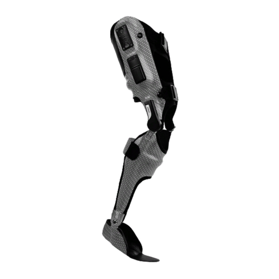
Summary of Contents for Otto Bock E-MAG Active 17B203-L
- Page 1 17B203=* E-MAG Active Gebrauchsanweisung (Fachpersonal) ..............Instructions for use (qualified personnel) ..............25...
- Page 2 17B203=* E-MAG Active...
- Page 3 Vorwort Deutsch 1 Vorwort INFORMATION Datum der letzten Aktualisierung: 2019-05-13 ► Lesen Sie dieses Dokument vor Gebrauch des Produkts aufmerksam durch. ► Beachten Sie die Sicherheitshinweise, um Verletzungen und Produktschäden zu vermeiden. ► Weisen Sie den Benutzer in den sachgemäßen und gefahrlosen Gebrauch des Produkts ein. ►...
- Page 4 Produktbeschreibung 2.3 Bauteile/Konstruktion Lieferumfang (siehe Abb. 1) Pos. Stück Bezeichnung Artikelkennzeichen Gelenkschraube 30Y112 Axialscheibe 17BS203 Gelenkunterteil Senkkopfschrauben 501S137=M5x10 Anschlagpuffer 617G28=3-9 Zylinderstift 506A8=4x8 Buchse mit Bund 30Y295=* Gelenkoberteil Entriegelung 30Y353=* Abdeckung 30Y440=* Senkkopfschrauben mit Kreuzschnlitz 501S21=M2x5 Laminierdummy 30Y297=* Zylinderschraube 501T28=M6x20 Nicht im Lieferumfang enthalten Pos.
-
Page 5: Bestimmungsgemäße Verwendung
Bestimmungsgemäße Verwendung 2.4 Elektronische Komponenten Akkukabel und Rasteinheit 317E20 Akkudummy für Akku-Einlegerahmen 30Y103 Dummy für Akku 30Y124 Akku / Einlegerahmen-Set 317B20, 317Z21 Elektronikkabel 317E2 Dummy für Elektronik-Einlegerahmen 30Y100 Dummy für Elektronik 30Y123 Elektronik / Einlegerahmen-Set 317B3, 317Z13 Ladegerät 317L20 2.5 Zubehör INFORMATION Der nachträgliche Umbau des 5°... -
Page 6: Bedeutung Der Warnsymbolik
Sicherheit • Kontraktionen im Kniegelenk, die eine Entlastung der Kniegelenksperre verhindern • Unkontrollierbare Spastiken • Tuberanstützungen Zusätzliche Kontraindikationen beim Einsatz ohne Mitläufer: • Unphysiologische Abweichungen in Frontalebene • Unphysiologische Abweichungen in Sagittalebene • Instabilitäten des Kapsel-, Bandapparates Zusätzliche Kontraindikationen beim Einsatz mit Mitläufer: •... - Page 7 Sicherheit VORSICHT Verletzungsgefahr durch sich lösende Systemschienen Die Senkkopfschrauben für die Fixierung der Eingussschienen 17LS3=16, 17LS3=16-T mit einem Anzugsmo ment von 7 Nm und mit Loctite 241 646K13 sichern. VORSICHT Quetschgefahr Achten Sie auf eine freie Bewegung in der Beuge. Lassen Sie keine Überlappungen von Schäften zu. Das Knie gelenk hat einen max.
-
Page 8: Herstellung Der Gebrauchsfähigkeit
Herstellung der Gebrauchsfähigkeit HINWEIS Thermische Überbelastung des Orthesengelenks Beschädigung der Lagerscheiben durch unsachgemäße thermische Bearbeitung, Bewegungsverlust des Orthe sengelenks ► Führen Sie keine Wärmebehandlung durch. ► Kontrollieren Sie die Funktion des Orthesengelenks. ► Beschädigte Lagerscheiben ersetzen. VORSICHT Knie bei Fersenauftritt nicht vollständig gestreckt Verletzungsgefahr durch nicht gesperrtes Orthesengelenk ►... - Page 9 Herstellung der Gebrauchsfähigkeit HINWEIS Beschädigung der Steuerungselektronik Verwenden Sie bis zur Fertigstellung der Orthese bei allen Arbeitsschritten die beigelegten Dummys. Tauschen Sie diese erst unmittelbar vor Anprobe oder Fertigstellung gegen die Elektronikkomponenten aus. Das Gelenk oberteil des E-MAG Kniegelenkes besitzt zur Befestigung der Eingussschienen Gewinde mit Sackbohrungen. Benutzen Sie nur die M5 x 10 Schrauben aus dem Lieferumfang, um Beschädigungen der Steuerungs-Elektronik im Gelenkoberteil des E-MAG Kniegelenkes zu vermeiden.
- Page 10 Herstellung der Gebrauchsfähigkeit Die Weichteilregionen auswählen und das Gewebe der Form der Laminierdummys anpassen. Das Gipspositiv in den ausgewählten Regionen so anpassen, dass die Laminierdummys plan aufliegen. Bei der Bauteileanordnung die Länge der Kabel beach ten: Akku – Elektronik: 500 mm, variable Länge •...
- Page 11 Herstellung der Gebrauchsfähigkeit Die Orthese nach den Anforderungen des Patienten profils armieren. Ansicht von lateral. INFORMATION: Optional kann die Technische Information zur Or thesenherstellung "Definitivorthese herstellen – Ganzbeinorthese" 646T5441 verwendet werden. Verfügbar auf Deutsch und Englisch. Weitere Spra chen auf Anfrage.an. Verkleidungsschale herstellen VORSICHT Beschädigung durch Einbaufehler...
- Page 12 Herstellung der Gebrauchsfähigkeit Die Kabelnut in den Laminierdummy fräsen. Die Laminierdummys für die Elektronikkomponenten auf dem Modell platzieren. Die Länge der beiliegenden Kabeldummys abmessen: Für den Laminierdummy 7 mm zwischen Kniege • lenk und Elektronik. • Den Perlondraht für das Kabel von der Elektronik zum Akku.
- Page 13 Herstellung der Gebrauchsfähigkeit Die Armierung für die Verkleidungsschale aufbringen: • 1 Lage Nylonstrumpf 99B25 über die fertige Orthe se ziehen. • Ein PVA-Folienschlauch überziehen. • 2 Lagen Perlontrikot über das Modell ziehen. • 2 Lagen Carbongewebe auf den Dummys fixieren. •...
- Page 14 Herstellung der Gebrauchsfähigkeit Die Verkleidungsschale drehen, so dass von innen die Einlegerahmen zu sehen sind. Eine kleine Menge Sie gelharz mit einer ausreichenden Menge Härter anrüh ren. Nicht zu viel Härter verwenden, da das Harz sonst beim Aushärten Blasen bildet und die Verbindung sprö de wird.
- Page 15 Herstellung der Gebrauchsfähigkeit HINWEIS: Das Kabel zwischen Orthesengelenk und Elektro nik darf weder gekürzt noch verlängert werden. INFORMATION: Bei Überlänge der Kabel verlegen Sie das Kabel in flachen Schlaufen und fixieren es mit doppelseitigem Klebeband in der Verklei dungsschale. Zur Installation der elektrischen Komponenten die Dum mys für Elektronik und Akku aus den Einlegerahmen entfernen.
- Page 16 Herstellung der Gebrauchsfähigkeit Das Akkukabel durch den Einlegerahmen führen. Die Rasteinheit des Akkukabels zusammenfügen. Dazu die Arbeitsschritte 1 bis 5 durchführen. Das Kabel von der Elektronik zum Akku verlegen. Mit doppelseitigem Klebeband das Kabel in der Kabelrinne der Verkleidungsschale fixieren. INFORMATION: Durch die Verwendung von Sili...
- Page 17 Herstellung der Gebrauchsfähigkeit Die Elektronik in den Einlegerahmen einlegen. Die Elektronik mit den beigefügten Schrauben mit max. 1 Nm fixieren. Das Elektronikkabel mit dem Orthesengelenk verbin den: • Die Schrauben der Abdeckung des E-MAG Orthe sengelenks lösen. • Die Abdeckung abnehmen. •...
- Page 18 Herstellung der Gebrauchsfähigkeit Die Abdeckung mit den Schrauben auf dem E-MAG Orthesengelenks fixieren. Die Verkleidungsschale auf dem Orthesenoberteil fixieren. Nach einer vollständigen Aufladung und Einlegen des Akkus ist das E-MAG Orthesengelenk betriebsbereit. 5.3 Arbeitshinweise elektronische Komponenten 5.3.1 Steuerungselektronik Die Steuerungselektronik misst die Position der Orthese während des Gangzyklus und öffnet das Orthesenkniege lenk vor Zehenablösung.
- Page 19 Herstellung der Gebrauchsfähigkeit 2) Ist das Gelenk offen, blinken die grüne und weiße LED und es ist ein Wechselton (Ton, Pause, Ton) in Dauer folge zu hören. Wenn das Gelenk in die Streckung gebracht wird, meldet das System OK, wie unter 1. be schrieben.
- Page 20 Herstellung der Gebrauchsfähigkeit 3) Der Patient wird gebeten, sein Bein mit der Orthese in einen Vorschritt zu bringen (ähnliche Position wie bei ei nem Fersenauftritt). Der Patient verharrt kurz in der Position, bis der Techniker die Position mit einem Druck auf den oberen Druckknopf B (siehe Seite ) bestätigt.
- Page 21 Herstellung der Gebrauchsfähigkeit Für besondere Gelegenheiten (z. B. Fahrradfahren) kann es sinnvoll sein, dass E-MAG Active Gelenk temporär zu entriegeln. Die mechanische Entriegelung des Systems erfolgt direkt am Kniegelenk (Schalter auf „ “). Um die Funktionsfähigkeit des E-MAG Active Gelenks wiederherzustellen ist es notwendig die Entriegelung wieder auf zu heben.
- Page 22 Reinigung 6 Reinigung Die Orthesengelenke müssen nach dem Kontakt mit salz-, chlor- oder seifenhaltigen Wasser oder bei Verschmut zungen umgehend gereinigt werden. 1) Bei Verschmutzungen das Gelenk mit einem feuchten Tuch reinigen. 2) Mit einem fusselfreien Tuch abtrocknen und an der Luft vollständig trocknen lassen. Direkte Hitzeeinwirkung vermeiden (z. B.
- Page 23 Wartungshinweise INFORMATION Dokumentieren Sie Ihre Wartungsarbeiten und -intervalle. Wir empfehlen, den Wartungsplan am Ende dieses Do kuments als Kopiervorlage zu nutzen und ihn nach Abschluss des Auftrags Ihren Unterlagen hinzuzufügen. Wei sen Sie auch Ihren Kunden auf die notwendigen Wartungsintervalle hin. INFORMATION: Bei Fehlfunktion des Magneten, der Elektronik oder des Schaltstifts kontaktieren sie den Ottobock Support.
- Page 24 Wartungshinweise 7.3 Wartungsplan Wartungsplan zur regelmäßigen Überprüfung E-MAG Active Patient: 1. Benut Seriennummer: Patientengewicht [kg]: ....zung am: Li. □ Re. □ Körpergröße [cm]: ....Prüfung (Checkliste zum Abhaken) Mitläufer Serien nummer: Pos. Bereich nein Maßnahme Orthesenkniegelenk Verschmutzung/Verschleiß? Gelenkspiel im gesperrten Zustand (ML)? Gelenkspiel im freien Zustand (ML)? Entriegeln/Verriegeln Funktion störungs...
-
Page 25: Technische Daten
Technische Daten 8 Technische Daten Temperaturbereich Lagerung -20 °C bis +70 °C (-4 °F bis 176 °F) Temperaturbereich Betrieb -15 °C bis +50 °C (-5 °F bis 122 °F) Luftfeuchtigkeit für beide Bereiche 15 % bis 93 % Stromversorgung Gelenk NiMh Akku, 4,8 V Nennspannung Reichweite eines Akkupacks ca. 5.000 Schritte, entspricht ca. 5 km 9 Entsorgung Das Produkt gemäß... - Page 26 Product description 2.2 Function/design Function The E-MAG Active is an orthotic knee joint system with stance phase control which offers the user a free swing phase and locks the knee joint for a secure stance phase prior to heel strike. The E-MAG Active features an electronic lock that is released during toe-off, allowing the user to swing the para...
-
Page 27: Electronic Components
Product description Scope of delivery (see fig. 1) Item Quantity Description Reference number Countersunk head screws 501S137=M5x10 Stop bumper 617G28=3-9 Cylinder pin 506A8=4x8 Bushing with collar 30Y295=* Upper joint section Unlocking mechanism 30Y353=* Cover 30Y440=* Countersunk Phillips head screws 501S21=M2x5 Lamination dummy 30Y297=* Cap screw 501T28=M6x20... -
Page 28: Intended Use
Intended use 3 Intended use 3.1 Indications for use The product is intended exclusively for orthotic devices for the lower limbs, for dynamic knee-ankle-foot orthoses and knee orthoses with a free swing phase and locked stance phase. The manufacturer recommends that the orthotic knee joint be processed using lamination technology or carbon prepreg technology when used on one side of the body and in pairs. - Page 29 Safety CAUTION Risk of injury due to the use of unapproved components or spare parts Components and spare parts that have not been authorised by the manufacturer may break. Only use compon ents and spare parts approved by the manufacturer for installation and service. CAUTION Explosion hazard Do not throw the battery into fire.
- Page 30 Safety CAUTION Exposure of the product to unsuitable environmental conditions Patient injury, damage, brittleness or destruction due to improper handling ► Do not expose the product to condensing ambient humidity or liquids. ► Do not expose the product to abrasive substances (e.g. sand, dust). ►...
-
Page 31: Preparation For Use
Preparation for use 5 Preparation for use 5.1 Processing Installation in the orthosis: This section describes the steps required to install the E-MAG knee joint system in an orthosis. It also includes instructions for fabricating a casing which is attached to the outer socket and protects the electronics, cables and battery housing from outside influences. - Page 32 Preparation for use Select the soft tissue regions and adapt the fibre mesh to the shape of the lamination dummies. Adapt the plaster positive in the selected regions so the lamination dummies lie flat. Note the length of the cables when positioning the com ponents: Battery –...
- Page 33 Preparation for use Reinforce the orthosis according to the requirements of the patient profile. Lateral view. INFORMATION: The 646T5441 technical information for orthosis fabrication titled “Fabricating a definitive knee- ankle-foot orthosis” can be optionally used. Avail able in German and English. Other languages available on request.
- Page 34 Preparation for use Mill the cable groove into the lamination dummy. Position the lamination dummies for the electronic com ponents on the model. Measure the length of the supplied cable dummies: For the lamination dummy, 7 mm between the knee • joint and electronics.
- Page 35 Preparation for use Apply the reinforcement for the casing: • Pull one layer of 99B25 nylon stockinette over the finished orthosis. • Pull over one PVA bag. • Pull two layers of Perlon stockinette over the model. • Secure two layers of carbon fibre mesh on the dum mies.
- Page 36 Preparation for use Turn the casing so the receptacles are visible from the inside. Mix a small amount of sealing resin with a suffi cient amount of hardener. Do not use too much harden er, since this could cause bubbles to form in the resin during hardening and make the connection brittle.
- Page 37 Preparation for use NOTICE: The cable between the orthotic knee joint and elec tronics may not be shortened or extended. INFORMATION: If there is excess cable length, lay the cable in flat loops and secure it in the casing with double-sided adhesive tape. To install the electrical components, remove the dum...
- Page 38 Preparation for use Thread the battery cable through the receptacle. Assemble the locking unit of the battery cable. Perform steps 1 through 5 to do so. Install the cable from the electronics to the battery. Secure the cable in the cable channel of the casing using double-sided adhesive tape.
- Page 39 Preparation for use Insert the electronics into the receptacle. Fasten the electronics using the supplied screws at a maximum torque of 1 Nm. Connect the electronics cable to the orthotic joint: • Loosen the screws of the cover on the E-MAG orthotic joint.
- Page 40 Preparation for use Secure the cover on the E-MAG orthotic joint using the screws. Secure the casing on the upper part of the orthosis. The E-MAG orthotic joint is ready for operation after fully char ging and inserting the battery. 5.3 Working instructions for electronic components 5.3.1 Control electronics The electronic control unit measures the position of the orthosis during the gait cycle and unlocks the orthotic joint...
- Page 41 Preparation for use 2) If the joint is open, the green and white LEDs flash accompanied by a continuous alternating tone sequence (tone, pause, tone). Once the joint is extended, the system reports “OK” as described under 1. 3) Sensor error. Continuously illuminated (red) and continuous sound. Remove and then reinsert the battery. 5.3.1.2 Initial walking in test mode Initial walking attempts (see fig. 35) should definitely be made between parallel bars or at least with the help of crutches.
- Page 42 Preparation for use 5) The software now reports that the joint is in calibration mode. The patient can then walk in the locked state until the software uses a different audible tone to warn the patient that the joint is about to automatically unlock at the end of the stance phase in order to facilitate an unobstructed swing-through.
- Page 43 Preparation for use CAUTION Risk of falling due to unlocking / locking Both permanent and one-time unlocking as well as permanent locking of the system can result in an elevated risk of falling. The patient should not use these functions whilst walking. 5.3.1.9 Alarm configuration Signal Visual feedback (LEDs)
-
Page 44: Maintenance Instructions
Cleaning 6 Cleaning After contact with water containing salt, chlorine or soap, or if they get dirty, the orthotic joints must be promptly cleaned. 1) Clean the joint with a damp cloth when needed. 2) Dry it with a lint-free cloth and allow it to air dry fully. Do not expose to direct heat sources (e.g. sunlight, stove or radiator). - Page 45 Maintenance instructions INFORMATION: If the magnet, electronics or actu ating bolt malfunction, contact Ottobock Support. Check the components for soiling: • Remove the joint cover. • To check the lock, remove the countersunk head screw (item 7) and the lock cover (item 6). Optional: Remove dirt from the spring (item 1) and •...
-
Page 46: Maintenance Schedule
Maintenance instructions 7.3 Maintenance schedule Maintenance schedule for regular service E-MAG Active Patient: First used Serial number: Patient weight [kg]: ....Left □ Right □ User height [cm]: ....Inspection (checklist for ticking off) Medial support serial num ber: Item Department Measure Orthotic knee joint... -
Page 47: Technical Data
Technical data 8 Technical data Storage temperature range -20 °C to +70 °C (-4 °F to 176 °F) Operating temperature range -15 °C to +50 °C (-5 °F to 122 °F) Relative humidity for both ranges 15% to 93% Power supply for joint NiMh battery, 4.8 V nominal voltage Range of a battery pack Approx. - Page 48 17B203=* E-MAG Active...
- Page 49 17B203=* E-MAG Active...
- Page 50 17B203=* E-MAG Active...
- Page 51 T +49 5527 848-3455 · F +49 5527 848-1510 Otto Bock France SNC healthcare@ottobock.de · www.ottobock.de 4 rue de la Réunion - CS 90011 Industria Ortopédica Otto Bock Unip. Lda. 91978 Courtaboeuf Cedex · France Av. Miguel Bombarda, 21 - 2º Esq. Otto Bock HealthCare Deutschland GmbH T +33 1 69188830 · F +33 1 69071802 1050-161 Lisboa ·...
- Page 52 Ottobock SE & Co. KGaA Max-Näder-Straße 15 · 37115 Duderstadt · Germany T +49 5527 848-0 · F +49 5527 848-3360 healthcare@ottobock.de · www.ottobock.com...
Need help?
Do you have a question about the E-MAG Active 17B203-L and is the answer not in the manual?
Questions and answers