Table of Contents
Advertisement
Quick Links
Advertisement
Table of Contents

Related Manuals for Panasonic AJ-CX4000G


Summary of Contents for Panasonic AJ-CX4000G
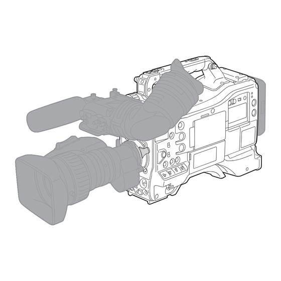
- Page 1 Operating Instructions Memory Card Camera-Recorder AJ-CX4000G Model No. Before using this product, be sure to read “Read this first!” (pages 2 to 7). Before operating this product, please read the instructions carefully and save this manual for future use. ENGLISH...
-
Page 2: Read This First
Read this first! Read this first! indicates safety information. WARNING: CAUTION: • To reduce the risk of fire, do not expose this Do not lift the unit by its handle while the tripod is attached. When the tripod is attached, its weight equipment to rain or moisture. - Page 3 NOTIFICATION (Canada) CAN ICES-3(B)/NMB-3(B) AEEE Yönetmeliğine Uygundur. AEEE Complies with Directive of Turkey. Manufactured by: Panasonic Corporation, Osaka, Japan Importer’s name and address of pursuant to EU rules: Panasonic Marketing Europe GmbH Panasonic Testing Centre Winsbergring 15, 22525 Hamburg, Germany...
- Page 4 Ovime, tvrtka “Panasonic Corporation” izjavljuje da Verklaring van Conformiteit (DoC) ovaj proizvod udovoljava osnovnim zahtjevima i ostalim Bij dezen verklaart “Panasonic Corporation” dat dit product relevantnim odredbama Direktive 2014/53/EU. in overeenstemming is met de essentiële vereisten en Kupci mogu preuzeti kopiju originalne DoC za naše RE andere relevante uiteenzettingen van Richtlijn 2014/53/EU.
- Page 5 Försäkran om Överensstämmelse (DoC) Δήλωση Συμμόρφωσης (DoC) Härmed garanterar “Panasonic Corporation” att denna Η “Panasonic Corporation” δηλώνει ότι το προϊόν αυτό produkt överensstämmer med tillämpbara krav och andra είναι συμμορφωμένο προς τις βασικές απαιτήσεις και άλλες föreskrifter i enlighet med direktiv 2014/53/EU.
- Page 6 Read this first! Disposal of Old Equipment and Batteries Only for European Union and countries with recycling systems These symbols on the products, packaging, and/or accompanying documents mean that used electrical and electronic products and batteries must not be mixed with general household waste. For proper treatment, recovery and recycling of old products and used batteries, please take them to applicable collection points in accordance with your national legislation.
- Page 7 Рік: остання цифра року (5 – 2015, 6 – 2016,…0 – 2020) Місяць: А – Січень, В – Лютий… L – Грудень Декларація про відповідність Справжнім компанія Panasonic Corporation заявляє, що професійні відеокамери AJ-CX4000 відповідають Технічному регламенту радіообладнання. Повний текст декларації про відповідність доступний на веб- сайті...
- Page 8 Select “LICENSE.TXT” in the external drive recognized by the computer. For details on these descriptions (originally provided in English) and how to obtain the source code, visit the following website. https://pro-av.panasonic.net/ We do not accept inquiries about the details of the source code obtained by the customer.
- Page 9 How to read this document r Illustrations f Illustrations of the product appearance, menu screens, etc., may vary from the actual. r Conventions used in this manual f Words and phrases in [ ] brackets indicate content displayed in the LCD monitor, etc. f Words and phrases in <...
-
Page 10: Table Of Contents
Contents Contents Read this first! [VIDEO OUT/LCD/VF] menu [RECORDING] menu Chapter 1 Overview [NETWORK] menu [SYSTEM] menu Before using the camera [OTHERS] menu Accessories [OPTION] menu Factory setting value of the scene file When turning on the power for the first time [AREA SETTINGS] [SCENE FILE] menu [TIME ZONE]... - Page 11 Contents Chapter 11 Specification Adjusting and setting the viewfinder Using the viewfinder Dimensions Handling setting data Specifications File structure of the setting data General Operating SD cards Camera unit Setup file Memory card recorder Scene file Digital video Scene files Digital audio Returning the setting value of the menu to the factory setting Streaming...
-
Page 12: Chapter 1 Overview
Overview Chapter 1 Before using the camera, read this chapter. -
Page 13: Before Using The Camera
Panasonic will not assume liability when video or audio recording fails due to a malfunction of the camera or the memory card during the use. f Set the calendar (datetime of the internal clock) and the time zone, or check the setting before recording. This will have an effect on the management of the recorded contents. - Page 14 Security Take caution in handling the camera or memory card so it is not stolen, lost or neglected, and handle with care when discarding. Note that Panasonic is not liable to leakage, falsification, or loss of information caused by them.
-
Page 15: Accessories
Chapter 1 Overview — Accessories Accessories Mount cap (already attached to the product) (page 20) Shoulder strap (page 44) NOTE t Appropriately discard the packing materials after taking the product out. – 15 –... -
Page 16: When Turning On The Power For The First Time
Chapter 1 Overview — When turning on the power for the first time When turning on the power for the first time The camera is shipped with the region of use not set. [AREA SETTINGS] is displayed in the LCD monitor when the power is turned on for the first time. Follow the guidance and make the settings in the order of [AREA SETTINGS], [TIME ZONE], and then [CLOCK SETTING]. -
Page 17: [Time Zone]
Chapter 1 Overview — When turning on the power for the first time [TIME ZONE] Set the time difference from the Greenwich Mean Time. TIME ZONE +0:00 Set the time difference. Select [SET]. Once the setting for [TIME ZONE] is completed, the [CLOCK SETTING] screen is displayed. NOTE t The setting for the date/time of the camera changes together with the time zone settings. -
Page 18: Use Of The Camera On A System
A battery holder is provided as standard on the main unit. For the latest information not included in these Operating Instructions, refer to the support desk at the following website. https://pro-av.panasonic.net/ Expanded configuration devices The following devices are also available in addition to the basic configuration devices. -
Page 19: Chapter 2 Description Of Parts
Description of Parts Chapter 2 This chapter describes the names, functions, and operations of parts on the camera. -
Page 20: Power Supply And Accessory Mounting Section
Chapter 2 Description of Parts — Power supply and accessory mounting section Power supply and accessory mounting section 17 11 1 Power switch Switches between power on/standby. To turn on, set the power switch to < j > (ON). To set to standby, set the power switch to < h > (standby). NOTE t Even when the power switch is set to the <... -
Page 21: Power Supply And Accessory Mounting Section
Chapter 2 Description of Parts — Power supply and accessory mounting section 16 Accessory mounting holes Attaches accessories. Do not attach anything other than an accessory. f Mounting hole size - 1/4-20 UNC (screw length 10 mm or shorter) - 3/8-16 UNC (screw length 10 mm or shorter) 17 Light shoe Attaches the video light, etc. -
Page 22: Audio (Input) Function Section
Chapter 2 Description of Parts — Audio (input) function section Audio (input) function section 1 <F.AUDIO LEVEL> dial Adjusts the recording level of the audio channel selected in the [AUDIO] menu → [REC CH SETTINGS] → [VOL. SELECT] when the <AUDIO SELECT CH1/3>/<AUDIO SELECT CH2/4>... - Page 23 Chapter 2 Description of Parts — Audio (input) function section 10 Cable holder Fixes the cables for lights or microphone. 11 <MIC IN> terminal Connects an external microphone (optional). f When using the phantom microphone, set to the [AUDIO] menu → [INPUT SETTINGS] → [FRONT MIC POWER] → [ON]. When it is set to [ON] and a microphone is not connected, low-frequency noise may occur.
-
Page 24: Audio (Output) Function Section
Chapter 2 Description of Parts — Audio (output) function section Audio (output) function section 1 <MONITOR> dial Adjusts the volume of the monitor audio during playback, recording, and recording standby. 2 <ALARM> dial Adjusts the volume of the alarm from the built-in speaker and earphones. When set to the minimum position, the alarm cannot be heard. -
Page 25: Shooting And Recording/Playback Functions Section
Chapter 2 Description of Parts — Shooting and recording/playback functions section Shooting and recording/playback functions section Shooting and recording (Camera unit) 7 8 9 10 1 <SYNCHRO SCAN> button Adjusts the shutter speed of synchro scan in the synchro scan mode. Pressing the <−>... -
Page 26: Shooting And Recording/Playback Functions Section
Chapter 2 Description of Parts — Shooting and recording/playback functions section 6 <AUTO W/B BAL> switch <AWB>: White balance is automatically adjusted. When this switch is operated with the <WHITE BAL> switch on the side set to <A> or <B>, adjustment is performed in several seconds and adjustment values are stored in memory. -
Page 27: Shooting And Recording/Playback Functions Section (Recording Unit)
Chapter 2 Description of Parts — Shooting and recording/playback functions section Shooting and recording/playback functions section (Recording unit) 1 <REC> button Recording is started by pressing the <REC> button. Recording is stopped by pressing this button again. Performs the same operation as the <VTR> button of the lens to be attached. 2 Card access lamp 1/card access lamp 2/card access lamp 3 Indicates the access status of recording and playback of the memory card. - Page 28 Chapter 2 Description of Parts — Shooting and recording/playback functions section 14 <SDI OUT1> terminal This is the output terminal only for SDI. Select an output signal in the [VIDEO OUT/LCD/VF] menu → [SDI OUT1] → [OUT FORMAT]. Superimposing of characters is set in the [VIDEO OUT/LCD/VF] menu → [SDI OUT1] → [SDI OUT CHAR]. 15 <SDI OUT2>...
-
Page 29: Menu Operation Section And Thumbnail Operation Section
Chapter 2 Description of Parts — Menu operation section and thumbnail operation section Menu operation section and thumbnail operation section 1 <MENU> button Press the <MENU> button to display menu on the viewfinder screen.Press it again to return to the previous display. There are two <MENU>... -
Page 30: Time Code Section
Chapter 2 Description of Parts — Time code section Time code section 1 <HOLD> button The time data indication on the counter display area is retained from the moment when this button is pressed. However, the time code generator continues to advance. Press the button again to release the retained state. This is used when you want to know the time code of the recorded scene or the counter data of the counter display. -
Page 31: Warning And Status Display Section
Chapter 2 Description of Parts — Warning and status display section Warning and status display section 1 <BRIGHT> button Controls the brightness of the display window. The brightness is switched in two levels every time the <BRIGHT> button is pressed. Regardless of the previous setting, it will display in dark setting when the power is turned on. -
Page 32: Display Inside The Display Window
Chapter 2 Description of Parts — Display inside the display window Display inside the display window Display of remaining memory card capacity, remaining battery level, and recording level SLAVE HOLD P-REC COUNTER MEDIA BATT 1 Time code indications [NDF] Displayed when the time code is in the non-drop frame mode. [DF] Displayed when the time code is in the drop frame mode. -
Page 33: Chapter 3 Preparation
Preparation Chapter 3 Before you use the camera, mount the battery and lens following the procedures in this chapter. The mounting of accessories is also described in this chapter. -
Page 34: Power Supply
Chapter 3 Preparation — Power supply Power supply A battery or an external DC power supply can be used as the power supply for the camera. To use a battery Connection of the following batteries to the camera has been verified. r Anton/Bauer battery Dionic/Hytron/Titon/Digital series NOTE... -
Page 35: Using External Dc Power Supply
Chapter 3 Preparation — Power supply Using V-mount type batteries Mount the V-mount type battery plate. As shown in the figure, insert and slide in the direction of the arrow. Release lever Mount the V-mount type battery plate. Slide in the direction of the arrow. Set the battery type. -
Page 36: Power Supply
Chapter 3 Preparation — Power supply DC IN +12 V Panasonic Parts No.: K1AA104H0038 Manufacturer Parts No.: HA16RX-4P (SW1) (76) (Hirose Electric Co.) NOTE t When both the battery and the external DC power supply are connected, the power supply from the external DC power supply has priority. The battery may be removed while using the external DC power supply. -
Page 37: Mounting And Adjusting The Lens
Chapter 3 Preparation — Mounting and adjusting the lens Mounting and adjusting the lens Mounting the lens Lens lever Center mark Mount cap Fig. 1 Fig. 2 Cable holders <LENS> terminal Fig. 4 Fig. 3 Raise the lens lever and remove the mount cap. (Fig. 1) Align the indentation at the top center of the lens mount with the center mark of the lens to mount the lens. -
Page 38: Adjusting Lens Flange Back
Chapter 3 Preparation — Mounting and adjusting the lens Adjusting lens flange back If images are not clearly focused at both telephoto and wide-angle positions during zoom operations, adjust the flange back (distance from the lens mounting surface to the image formation surface). Once adjusted, the flange back does not need to be readjusted until the lens is changed. -
Page 39: Chromatic Aberration Compensation Function (Cac)
Chapter 3 Preparation — Mounting and adjusting the lens 4) Confirm that the [SCENE FILE] menu → [GAMMA MODE SEL] → [HD] is set. 5) Confirm that the [VIDEO OUT/LCD/VF] menu → [EI ASSIST] is set to as follows. f Change the setting if it is different. [ZEBRA1 DETECT]: [70%] [ZEBRA2 DETECT]: [85%] [ZEBRA2]: [SPOT]... -
Page 40: Mounting And Adjusting The Lens
For details on additions and modifications to lenses compatible with the chromatic aberration compensation function, visit the support desk at the following website: https://pro-av.panasonic.net/ Operation of chromatic aberration compensation function Operate in following steps when a chromatic aberration compensation function compatible lens is mounted to the camera. -
Page 41: Mounting And Adjusting The Lens
[OTHERS] menu → [FILE] → [SLOT FOR LOAD/SAVE]. For details on downloading, refer to the following website. https://pro-av.panasonic.net/ Select the [OTHERS] menu → [FILE] → [CAC FILE(SD CARD)] → [LOAD]. (Fig. 1) The list of CAC files on the SD card is displayed. -
Page 42: Mounting And Adjusting The Lens
Chapter 3 Preparation — Mounting and adjusting the lens t When an error message is also not displayed while the chromatic aberration compensation function is not functioning, the software version of the lens might be old. Contact the manufacturer of the lens you are using. –... -
Page 43: Preparing For Audio Input
Chapter 3 Preparation — Preparing for audio input Preparing for audio input Prepare the camera for connecting audio input devices. Using the front microphone Microphones such as the stereo microphone kit AJ-MC900G (optional) can be mounted. Viewfinder clamping screw Viewfinder Microphone holder <MIC IN>... -
Page 44: Mounting Accessories
Chapter 3 Preparation — Mounting accessories Mounting accessories Mounting the camera on a tripod When mounting the camera on a tripod, use the optional tripod adaptor (SHAN-TM700). Tripod adaptor Pan head Fig. 1 Fig. 2 Mount the tripod adaptor on the tripod. (Fig. 1) Mount the camera on the tripod adaptor. -
Page 45: Attaching The Rain Cover
Chapter 3 Preparation — Mounting accessories Attaching the rain cover The figure below shows an example of use of the rain cover SHAN-RC700 (optional). Tighten the cord Secure with the surface fastener – 45 –... -
Page 46: Charging The Built-In Battery
Chapter 3 Preparation — Charging the built-in battery Charging the built-in battery The date/time set in the camera is maintained by the built-in battery. The built-in battery may be consumed when the power of the camera is not turned on for approximately a half year. The built-in battery has been consumed if [BACKUP BATT EMPTY] is displayed in the viewfinder screen for approximately five seconds when the power switch is set to <... -
Page 47: Setting The Date/Time Of The Internal Clock
Chapter 3 Preparation — Setting the date/time of the internal clock Setting the date/time of the internal clock The date/time and time zone are recorded as metadata in the content (clip) while shooting. The date/time metadata will affect the playback order by the thumbnail. -
Page 48: Inspections Before Shooting
Chapter 3 Preparation — Inspections before shooting Inspections before shooting Before recording, perform the following inspection to ensure that the system operates properly. It is recommended that you check the image using a color video monitor. Preparing to inspect Card access lamp 14.6V RELAY Fig. -
Page 49: Power Supply
Chapter 3 Preparation — Inspections before shooting f Warning is not displayed in the viewfinder screen. Press the <REC> button again. Confirm that the card access lamp illuminates in orange and the [REC] lamp inside the viewfinder turns off. Use the <VTR> button on the lens and confirm the same operation as steps 2 to 3. Press the <BRIGHT>... -
Page 50: Inspections Before Shooting
Chapter 3 Preparation — Inspections before shooting Set the <TCG> switch to <F-RUN>. Ensure that the number in the counter display changes regardless of the recording status. Set the <DISPLAY> switch to <UB>. Ensure that the user bits displayed in the counter display area is correct. Ensure that the time zone, date, and time are correct by selecting the [OTHERS] menu →... -
Page 51: Preparing The Memory Card
- A memory card with 48 GB or more without the SDXC logo f Operation is not guaranteed for any memory cards other than the above. f Panasonic memory cards are recommended. f Following memory cards cannot be used. - P2 memory card... -
Page 52: Memory Cards
Chapter 3 Preparation — Memory cards Memory cards Inserting the memory card When using the camera for the first time, be sure to set the time data beforehand. (page 47) This camera uses the card slot 1 dedicated for a expressP2 card, and the card slot 2/3 for a microP2 card or a SD card. Card slot 1 Card access lamp Eject button... -
Page 53: Preventing Accidental Erasure
Chapter 3 Preparation — Memory cards f For microP2 card or SD card - Press in the microP2 card or SD card further inside and let go. - Remove the microP2 card or SD card when it comes out from the slot. NOTE t Do not remove the memory card while it is being accessed or while the card access lamp is flashing in orange after it is inserted. -
Page 54: Memory Card Recording Time
Chapter 3 Preparation — Memory cards Memory card recording time When the recording mode is P2 Uses expressP2 card and microP2 card. Recording capacity Recording format 64 GB AVC-Intra 422 Approx. 32 minutes AVC-LongG50 Approx. 128 minutes AVC-LongG25 (1080-59.94p/50.00p) Approx. 128 minutes AVC-LongG25 (1080-59.94i/50.00i, Approx. -
Page 55: Handling Recording Data
Viewer Plus” to prevent data loss. For details on downloading P2 Viewer Plus and the operating environment, visit the support desk at the following website: https://pro-av.panasonic.net/ t Follow the instructions below when using a general IT tool such as the OS standard file manager equipped on a computer to transfer a recording data in P2 format to a computer. -
Page 56: Memory Cards
Chapter 3 Preparation — Memory cards Volume label of the memory card r When the recording mode is P2 The card serial number is stored in the volume label if the memory card being used is the microP2 card. “CAM_SD” is stored in the volume label if a card other than the microP2 card is used. -
Page 57: Memory Cards
Chapter 3 Preparation — Memory cards 3 Clip number C001 - C999 f This is a sequential number assigned to each recording on the memory card. The number returns to C001 when the memory card is formatted. It will also return to C001 for the one after C999. The clip number is maintained even when the folder is split or when the clip is deleted. -
Page 58: Chapter 4 Operation
Operation Chapter 4 This chapter describes how to operate the screen of this camera, how to operate the menu, the structure of the menu, and details of the menu. -
Page 59: Basic Operation Of The Menu
Chapter 4 Operation — Basic operation of the menu Basic operation of the menu The setting of the camera can be changed with the menu in accordance to the shooting scene or recording contents. Set data is written and saved in the camera memory. f There are two methods of operation, a method to operate with the jog dial button or the cursor operation button, and a method to touch the LCD monitor. - Page 60 Chapter 4 Operation — Basic operation of the menu - Press the <EXIT> button. - Press the cursor operation button. - Place the cursor on [EXIT] at the top and press the <SET> button or the jog dial button. Select the item to set. 1) Turn the jog dial button to move the cursor to the item to set.
-
Page 61: Menu Display
Chapter 4 Operation — Menu display Menu display Displaying the menu Displays the menu, and select the menu or item to set. Press the <MENU> button when not recording. The menu is displayed. CAMERA SCENE FILE AUDIO VIDEO OUT/LCD/VF RECORDING NETWORK SYSTEM OTHERS... -
Page 62: Menu Settings
Chapter 4 Operation — Menu settings Menu settings [THUMBNAIL] menu Performs confirmation or deleting of the recording clip. This menu can be set when the thumbnail screen is displayed. [PLAYBACK] Sets the playback of recorded clips. [CLIP SEL] Selects a clip to be displayed on the thumbnail screen. It is always displayed in [ALL SLOT] when switched from the camera image screen to the thumbnail screen. -
Page 63: Menu Settings
Chapter 4 Operation — Menu settings [SHUTTER SPEED] The items that can be set in [POSITION1] to [POSITION6] are as follows. f When the [SYSTEM] menu → [FREQUENCY] → [59.94Hz] is set - [OFF], [1/100], [1/120], [1/250], [1/500], [1/1000], [1/2000], [HALF] f When the [SYSTEM] menu →... -
Page 64: Menu Settings
Chapter 4 Operation — Menu settings (Factory setting: [L/M/H]) [DS.GAIN OFF] Selects a method to release digital super gain mode (accumulated gain). [L/M/H] The digital super gain mode is released in following cases. f When the <GAIN> switch setting is changed f When the USER button assigned with [DS.GAIN] is pressed [DS.GAIN] The digital super gain mode is released only when the USER button assigned with [DS.GAIN] is pressed. -
Page 65: Menu Settings
Chapter 4 Operation — Menu settings [ATW SPEED] Sets the control speed of the auto tracking white balance function. The items that can be set are as follows. f [FAST], [NORMAL], [SLOW] (Factory setting: [NORMAL]) [ATW TARGET R] Finely adjusts the Rch output for convergence with the auto tracking white balance operation. The items that can be set are as follows. -
Page 66: Menu Settings
Chapter 4 Operation — Menu settings (Factory setting: [30]) [A.IRIS WINDOW] Selects the auto iris detection window. [NORMAL1] Window that is around center of the screen. [NORMAL2] Window that is around bottom of the screen. [CENTER] Window that is a spot around center of the screen. (Factory setting: [NORMAL1]) [S.IRIS LEVEL] Sets the super iris (backlight compensation) target value. -
Page 67: Menu Settings
Chapter 4 Operation — Menu settings The items that can be set are as follows. f [−200]…[200] (Factory setting: [0]) [LENS R FLARE] Adjusts the Rch flare level. The items that can be set are as follows. f [0]…[100] (Factory setting: [0]) [LENS G FLARE] Adjusts the Gch flare level. -
Page 68: [Scene File] Menu
Chapter 4 Operation — Menu settings [R H SAW] Performs the white shading correction manually. Adjusts sawtooth waveforms and parabolic waveforms of RGB channels in the horizontal and vertical directions. [R H PARA] The items that can be set are as follows. [R V SAW] f [−255]…[255] [R V PARA]... -
Page 69: Menu Settings
Chapter 4 Operation — Menu settings [MASTER DTL] Sets the level of the detail effect of the whole part. The items that can be set are as follows. f [−31]…[31] [DTL CORING] Sets the level of signal (including noise) that does not activate the detail effect. The items that can be set are as follows. -
Page 70: Menu Settings
Chapter 4 Operation — Menu settings [SKIN TONE DTL C] Selects the skin tone table that will display the skin tone detail. Create the skin tone table with [DETECT TABLE]. You can shoot smoother skin tones by displaying the skin tone detail. You can use only [SKIN TONE DTL C] or use a combination of [SKIN TONE DTL C] and [SKIN TONE DTL A] or a combination of [SKIN TONE DTL C] and [SKIN TONE DTL B]. -
Page 71: Menu Settings
Chapter 4 Operation — Menu settings [R GAIN AWB B] Sets the Rch gain when the <WHITE BAL> switch is set to <B>. The items that can be set are as follows. f [−200]…[200] [B GAIN AWB B] Sets the Bch gain when the <WHITE BAL> switch is set to <B>. The items that can be set are as follows. - Page 72 Chapter 4 Operation — Menu settings [R GAIN] Displays the output of Rch when the <WHITE BAL> switch is <B> and automatic white balance is working, or when it is preset. In automatic white balance operation, the color can also be changed on the Rch axis by changing the output of Rch. The items that can be set are as follows.
-
Page 73: Menu Settings
Chapter 4 Operation — Menu settings [G-B] Adjusts the linear matrix. (Green - Blue) The items that can be set are as follows. f [−63]…[63] [B-R] Adjusts the linear matrix. (Blue - Red) The items that can be set are as follows. f [−63]…[63] [B-G] Adjusts the linear matrix. -
Page 74: Menu Settings
Chapter 4 Operation — Menu settings [Yl-R-R] ([SAT]) Corrects the color saturation between “colors between yellow and red” and red. [Yl-R-R] ([PHASE]) Corrects the hue between “colors between yellow and red” and red. [MASTER PED] Sets the master pedestal. The items that can be set are as follows. f [−200]…[200] [RGB BLACK CONTROL SETTING] [R PED]... -
Page 75: Menu Settings
Chapter 4 Operation — Menu settings [F-REC DYNAMIC LEVEL] When [FILM-REC] is selected in [GAMMA MODE SEL], dynamic range is set. No settings are changed if an item other than [FILM-REC] is selected. The items that can be set are as follows. f [200%] …... -
Page 76: Menu Settings
Chapter 4 Operation — Menu settings [HLG KNEE SW] Enables/disables the operation of knee for HLG. The items that can be set are as follows. f [ON], [OFF] [HLG KNEE POINT] Sets the position of the knee point for HLG. The items that can be set are as follows. -
Page 77: Menu Settings
Chapter 4 Operation — Menu settings [BLACK GAMMA] Sets the gamma curves of dark areas. [−8]…[−1] Compresses the dark area. [OFF] Standard state [1]…[8] Expands dark areas. [B.GAMMA RANGE] Sets the maximum level of compression/expansion. Around 20% Around 30% Around 40% [MATRIX TABLE] Selects the color correction table when the <GAIN>... -
Page 78: Menu Settings
Chapter 4 Operation — Menu settings Around 20% Around 30% Around 40% [MATRIX TABLE] Selects the color correction table when the <GAIN> switch is set to <M>. The items that can be set are as follows. f [A], [B], [OFF] [COLOR CORRECT] Enables/disables the [COLOR CORRECTION] function when the <GAIN>... -
Page 79: [Audio] Menu
Chapter 4 Operation — Menu settings [COLOR CORRECT] Enables/disables the [COLOR CORRECTION] function when the <GAIN> switch is set to <H>. The items that can be set are as follows. f [ON], [OFF] [DRS] Enables/disables the dynamic range stretcher function. If functions are assigned to the USER buttons, [ON]/[OFF] can be switched using the USER button operations. -
Page 80: Menu Settings
Chapter 4 Operation — Menu settings [FRONT MIC LEVEL] Sets the input level of the external microphone connected to the front <MIC IN> terminal of the camera. This is enabled only when an external microphone is connected to the <MIC IN> terminal. The items that can be set are as follows. -
Page 81: Menu Settings
Chapter 4 Operation — Menu settings [OFF] The <F.AUDIO LEVEL> dial is disabled regardless of the setting of the <AUDIO IN CH2> switch. (Factory setting: [OFF]) [FRONT VOL. CH3] Selects if the <F.AUDIO LEVEL> dial is enabled against the audio signal input to the audio channel 3. [FRONT] This is enabled when the <AUDIO IN CH3>... -
Page 82: Menu Settings
Chapter 4 Operation — Menu settings (Factory setting: [70]) [CH1 MIC LOWCUT] Enables/disables the lowcut filter for audio channel 1. The items that can be set are as follows. f [FRONT], [W.L.], [REAR], [OFF] (Factory setting: [OFF]) [CH2 MIC LOWCUT] Enables/disables the lowcut filter for audio channel 2. -
Page 83: [Video Out/Lcd/Vf] Menu
Chapter 4 Operation — Menu settings [HDMI OUT CH] Selects the audio channel to be output from the <HDMI> terminal. [CH1/2] Outputs the audio signals of the audio channel 1 and the audio channel 2 as stereo. [CH3/4] Outputs the audio signals of the audio channel 3 and the audio channel 4 as stereo. (Factory setting: [CH1/2]) [ALARM] [BATTERY NEAR END]... - Page 84 Chapter 4 Operation — Menu settings NOTE t For the combinations that can be set, refer to “Format that can be output from the <SDI OUT1> terminal” (page 178). [3G-SDI OUT] Sets the format of the 3G-SDI signal output from the <SDI OUT1> terminal. Can be set when the 3G-SDI signal is output.
- Page 85 Chapter 4 Operation — Menu settings [1280×720p] Outputs in 1280×720p. [720×480i] Outputs in 720×480i. [720×576i] Outputs in 720×576i. (Factory setting: [1920×1080i]) NOTE t For the combinations that can be set, refer to “Format that can be output from the <SDI OUT2> terminal” (page 178). [3G-SDI OUT] Sets the format of the 3G-SDI signal output from the <SDI OUT2>...
- Page 86 Chapter 4 Operation — Menu settings (Factory setting: [MENU ONLY]) [HDMI OUT] [SIGNAL SEL] Sets the signal to output from the <HDMI> terminal. The items that can be set are as follows. f [SDI OUT1(2160p)], [SDI OUT2] (Factory setting: [SDI OUT2]) NOTE t [SDI OUT1(2160p)] can be selected only when [OUT FORMAT] of [SDI OUT1] is set to [3840×2160p].
- Page 87 Chapter 4 Operation — Menu settings The items that can be set are as follows. f [−1], [0], [1], [2] (Factory setting: [0]) [SELF SHOOT] Sets the display of the LCD monitor when mirror shooting is performed. [NORMAL] Does not invert the left and right sides. [MIRROR] Inverts the left and right sides.
- Page 88 Chapter 4 Operation — Menu settings [STREAMING] Displays/hides the streaming status. The items that can be set are as follows. f [ON], [OFF] (Factory setting: [ON]) [NETWORK] Displays/hides the wireless LAN and wired LAN connection status. The items that can be set are as follows. f [ON], [OFF] (Factory setting: [ON]) [BATTERY REMAIN]...
- Page 89 Chapter 4 Operation — Menu settings The items that can be set are as follows. f [ON], [OFF] (Factory setting: [ON]) [SCENE FILE] Displays/hides scene file name. The items that can be set are as follows. f [ON], [OFF] (Factory setting: [ON]) [AUDIO LEVEL METER] Displays/hides the audio level meter.
- Page 90 Chapter 4 Operation — Menu settings (Factory setting: [OFF]) [SHOOTING MODE] Displays/hides high-sensitivity mode. The items that can be set are as follows. f [ON], [OFF] (Factory setting: [ON]) [EXTENDER] Displays/hides the display whether lens extender function is active. The items that can be set are as follows. f [ON], [OFF] (Factory setting: [ON]) [D.ZOOM]...
- Page 91 Chapter 4 Operation — Menu settings [SDI OUT1 MARKER] [CENTER MARKER] Switch the type of the center marker. + (large) Open center (large) + (small) Open center (small) [OFF] Does not display. (Factory setting: [1]) [SAFETY MARKER] Selects the type of frame for the safety zone marker. Corners [OFF] Does not display.
- Page 92 Chapter 4 Operation — Menu settings The items that can be set are as follows. f [4:3], [13:9], [14:9], [1.85:1], [2.35:1], [OFF] (Factory setting: [OFF]) [FRAME COLOR] Sets the color of the frame marker. The items that can be set are as follows. f [WHITE], [BLACK], [RED], [GREEN], [BLUE], [YELLOW] (Factory setting: [WHITE]) [LCD/VF MARKER]...
- Page 93 Chapter 4 Operation — Menu settings [10SEC] Disables the enlarged display function after ten seconds have elapsed. [HOLD] Enables the enlarged display function until the <FOCUS ASSIST> button or the USER button assigned with [EXPAND] is pressed. [UNTIL REC] Enables the enlarged display function until recording starts. (Factory setting: [10SEC]) [EXPAND VALUE] Adjusts the enlargement factor of the enlarged display function.
- Page 94 Chapter 4 Operation — Menu settings [LOW LIGHT LEVEL] Sets the amount of the light entering the camera to be the reference to display [LOW LIGHT]. The items that can be set are as follows. f [OFF], [10%], [15%], [20%], [25%], [30%], [35%] (Factory setting: [35%]) [WFM MODE] Sets the display of the waveform monitor.
-
Page 95: [Recording] Menu
Chapter 4 Operation — Menu settings The items that can be set are as follows. f [ON], [OFF] (Factory setting: [OFF]) [FILTER] Sets whether to illuminate the [!] lamp on the viewfinder for any setting combination other than the <CC FILTER> dial set to<A> (<3200 K>) and the <ND FILTER>... - Page 96 Chapter 4 Operation — Menu settings [RELAY REC] Sets to the relay recording. [SIMUL REC] Sets to the simultaneous recording. (Factory setting: [RELAY REC]) NOTE t For the combinations and restrictions of the settings, refer to “Recording function that cannot be used simultaneously” (page 208). [PRE REC] Sets whether to perform pre-recording.
-
Page 97: [Network] Menu
Chapter 4 Operation — Menu settings [FRAME RATE] Selects the image information (such as frame rate) of the camera. [USER] Selects the set user bits. [TIME] Selects the local time. (hh, mm, ss) [DATE] Selects the local date and time. (YY, MM, DD, hh) [TC] Records the time code value as user bits. - Page 98 Chapter 4 Operation — Menu settings The character limit of the user account name and password is as follows. f User account name: Maximum of 31 characters f Password: Between 8 to 15 characters [ACCOUNT LIST] Displays a list of registered user accounts. Also, confirmation screen for whether to delete the registered user is displayed when a user is selected.
- Page 99 Chapter 4 Operation — Menu settings [MULTICAST ADDRESS] Sets the address when using the streaming with the multicast. (Factory setting: [239.192.0.20]) [MULTICAST PORT] Sets the port number when using the streaming with the multicast. (Factory setting: [37004]) [LOAD (SD CARD)] Loads the settings file from the memory card and reflects in the menu when [CONNECTION INFO.] is set to [MEMORY].
- Page 100 Chapter 4 Operation — Menu settings (Factory setting: [DISABLE]) [MULTICAST ADDRESS] Sets the address when using the streaming with the multicast. (Factory setting: [239.192.0.20]) [MULTICAST PORT] Sets the port number when using the streaming with the multicast. (Factory setting: [37004]) [CLEAR ACTIVATION] Clears the activation license information that is saved.
- Page 101 Chapter 4 Operation — Menu settings [DIRECT] It can connect directly without using a wireless access point to a device equipped with wireless LAN such as a tablet terminal. [INFRA(SELECT)] Connects to the wireless access point. The access point is selected from the list. [INFRA(MANUAL)] Connects to the wireless access point.
-
Page 102: [System] Menu
Chapter 4 Operation — Menu settings [PRIMARY DNS] Sets the primary DNS server. f Disables the setting for the primary DNS server when [WLAN PROPERTY] → [TYPE] → [DIRECT] is selected. (Factory setting: [0.0.0.0]) [SECONDARY DNS] Sets the secondary DNS server. f Disables the setting for the secondary DNS server when [WLAN PROPERTY] →... -
Page 103: [Others] Menu
Chapter 4 Operation — Menu settings f When [FREQUENCY] is set to [59.94Hz], and [FILE FORMAT] is set to [MOV] The items that can be set are as follows. - [2160-59.94p/420LongGOP 150M], [2160-59.94p/HEVC LongGOP 200M], [2160-59.94p/HEVC LongGOP 100M], [2160-29.97p/420LongGOP 100M], [2160-29.97p/HEVC LongGOP 150M], [2160-29.97p/422LongGOP 150M], [2160-29.97p/422ALL-I 400M], [2160-23.98p/420LongGOP 100M], [2160-23.98p/HEVC LongGOP 150M], [2160-23.98p/422LongGOP 150M], [2160-23.98p/422ALL-I 400M], [1080-59.94p/422LongGOP 100M], [1080-59.94p/422ALL-I 200M], [1080-59.94i/422LongGOP 50M], [1080-59.94i/422ALL-I 100M], [1080-29.97p/422LongGOP 50M], [1080-29.97p/422ALL-I 100M], [1080-23.98p/422LongGOP 50M], [1080-23.98p/422ALL-I 100M]... - Page 104 Chapter 4 Operation — Menu settings The items that can be set are as follows. f [SLOT2], [SLOT3] (Factory setting: [SLOT2]) [BATTERY] [DC IN SOURCE] Sets the type of external power supply to input to the <DC IN> terminal. The items that can be set are as follows. [DC POWER SUPPLY] Select when connecting the AC adaptor.
- Page 105 Chapter 4 Operation — Menu settings The items that can be set are as follows. f [−100]…[100] (Factory setting: [0]) [H PHASE FINE] Performs fine adjustment to match horizontal synchronization phase when building a system. The items that can be set are as follows. f [−100]…[100] (Factory setting: [0]) [COLOR BARS]...
- Page 106 Chapter 4 Operation — Menu settings Minute [0]…[59] [TIME ZONE] Sets the time zone. It will switch to the time with the time difference added when the time zone setting is changed. The items that can be set are as follows. f [−12:00]…[+12:30] (30 minutes steps), [+12:45], [+13:00] (Factory setting: [+0:00]) [DATE FORMAT]...
-
Page 107: [Option] Menu
Chapter 4 Operation — Menu settings [English] English (Factory setting: [English]) f When [AREA SETTINGS] is set to [AREA 2] [English] English [Français] French [Español] Spanish (Factory setting: [English]) f When [AREA SETTINGS] is set to [AREA 3] [English] English [Français] French [Deutsch]... -
Page 108: Factory Setting Value Of The Scene File
Chapter 4 Operation — Factory setting value of the scene file Factory setting value of the scene file [SCENE FILE] menu Factory setting of each item in the scene file selected in the [SCENE FILE] menu → [FILE SELECT] are same values in [F1:] to [F6:]. f Meaning of the symbols used in the table are as follows. - Page 109 Chapter 4 Operation — Factory setting value of the scene file [SCENE FILE] menu item Factory setting [B-R] [B-G] [COLOR CORRECTION] [L COLOR CORRECT] [ON] [M COLOR CORRECT] [ON] [H COLOR CORRECT] [ON] 16-axis independent color correction item [PARAMETER] [MASTER PED] [16] [RGB BLACK CONTROL SETTING] [R PED]...
- Page 110 Chapter 4 Operation — Factory setting value of the scene file [SCENE FILE] menu item Factory setting [COLOR CORRECT] [ON] [HIGH SETTING] [MASTER GAIN] [12dB] [H.DTL LEVEL] [V.DTL LEVEL] [DTL CORING] [15] [DTL FREQ.] [LEVEL DEPEND.] [MASTER GAMMA] [0.55] [BLACK GAMMA] [B.GAMMA RANGE] [MATRIX TABLE] [COLOR CORRECT]...
-
Page 111: Target Items For Scene File/Setup File/Initialization
Chapter 4 Operation — Target items for scene file/setup file/initialization Target items for scene file/setup file/initialization f SCENE: Items saved in scene files. f SETUP: Items saved in setup files. f INITIALIZE: Items that are initialized with the [OTHERS] menu → [MENU INITIALIZE]. f Meaning of the symbols used in the table are as follows. -
Page 112: [Scene File] Menu
Chapter 4 Operation — Target items for scene file/setup file/initialization Item SCENE SETUP INITIALIZE [LENS FILE ADJ.] [LENS FILE ADJ. MODE] — — [LENS R GAIN OFFSET] — — [LENS B GAIN OFFSET] — — [LENS R FLARE] — — [LENS G FLARE] —... - Page 113 Chapter 4 Operation — Target items for scene file/setup file/initialization Item SCENE SETUP INITIALIZE [R GAIN AWB B] — [B GAIN AWB B] — [AWB A GAIN OFFSET] — [AWB B GAIN OFFSET] — [COLOR TEMP Ach [COLOR TEMP] — SETTING] [R GAIN] —...
-
Page 114: [Audio] Menu
Chapter 4 Operation — Target items for scene file/setup file/initialization Item SCENE SETUP INITIALIZE [LOW SETTING] [MASTER GAIN] — [H.DTL LEVEL] — [V.DTL LEVEL] — [DTL CORING] — [DTL FREQ.] — [LEVEL DEPEND.] — [MASTER GAMMA] — [BLACK GAMMA] — [B.GAMMA RANGE] —... -
Page 115: [Video Out/Lcd/Vf] Menu
Chapter 4 Operation — Target items for scene file/setup file/initialization Item SCENE SETUP INITIALIZE [CH3 LEVEL] — [CH4 LEVEL] — [CH1 LEVEL CONTROL] — [CH2 LEVEL CONTROL] — [CH3 LEVEL CONTROL] — [CH4 LEVEL CONTROL] — [CH1 MIC LOWCUT] — [CH2 MIC LOWCUT] —... - Page 116 Chapter 4 Operation — Target items for scene file/setup file/initialization Item SCENE SETUP INITIALIZE [REC MEDIA] — [SLOT STATUS] — [2 SLOTS FUNC.] — [STREAMING] — [NETWORK] — [BATTERY REMAIN] — [REC FORMAT] — [CLIP NAME] — [BONDING DEVICE] — [REC REMOTE] —...
-
Page 117: [Recording] Menu
Chapter 4 Operation — Target items for scene file/setup file/initialization Item SCENE SETUP INITIALIZE [DETAIL FREQ.] — [EI ASSIST] [ZEBRA1 DETECT] — [ZEBRA2 DETECT] — [ZEBRA2] — [LOW LIGHT LEVEL] — [WFM MODE] — [WFM TRANSPARENCE] — [!LED] [GAIN(0dB)] — [DS.GAIN] —... -
Page 118: [System] Menu
Chapter 4 Operation — Target items for scene file/setup file/initialization Item SCENE SETUP INITIALIZE [MULTICAST PORT] — [CLEAR ACTIVATION] — — — [LAN PROPERTY] [MAC ADDRESS] — — — [IPv4 SETTING] [DHCP] — [IP ADDRESS] — [SUBNET MASK] — [DEFAULT GATEWAY] —... -
Page 119: [Option] Menu
Chapter 4 Operation — Target items for scene file/setup file/initialization Item SCENE SETUP INITIALIZE [END VOLT] — [NEAR END INFO] — [END INFO] — [GENLOCK] [GENLOCK] — [H PHASE COARSE] — [H PHASE FINE] — [COLOR BARS] [COLOR BARS TYPE] —... -
Page 120: Chapter 5 Shooting
Shooting Chapter 5 This chapter describes the basic procedure for recording. This chapter also describes the special recording method. -
Page 121: Basic Procedures
Chapter 5 Shooting — Basic procedures Basic procedures This section describes the basic procedures for shooting and recording. Before you actually start shooting, pre-inspect your system to ensure that it works properly. (page 48) Preparing power supply and inserting memory cards Card access lamp Fig. -
Page 122: Adjustments For Shooting
Chapter 5 Shooting — Basic procedures a: <GAIN> switch Normally, set this to <L> (0 dB). If it is too dark, set the gain to an appropriate value. b: <OUTPUT>/<AUTO KNEE> switch Set this switch to <CAM>/<ON>. c: <TCG> switch Set this switch to <F-RUN>... -
Page 123: Adjusting The White And Black Balance
Chapter 5 Shooting — Adjusting the white and black balance Adjusting the white and black balance To obtain high-quality video at all times using the camera, the white and black balance must be adjusted according to conditions. Adjust the AWB (white balance adjustment), ABB (black balance adjustment), and AWB (white balance adjustment) in order to obtain higher image quality. - Page 124 Chapter 5 Shooting — Adjusting the white and black balance Detection range of white balance The white balance detection range can be selected from [90%], [50%], and [25%] in the [CAMERA] menu → [WHITE BALANCE MODE] → [AWB AREA].The factory setting value is [25%]. When having no time to adjust the white balance Set the <WHITE BAL>...
-
Page 125: Black Balance Adjustment
Chapter 5 Shooting — Adjusting the white and black balance NOTE t Even if color temperature is set manually, the color temperature adjusted automatically is recorded to the setting of the <WHITE BAL> switch at that time if white balance is automatically adjusted. The value of the color temperature also changed when the position of the <CC FILTER> dial is switched. -
Page 126: Setting The Electronic Shutter
Chapter 5 Shooting — Setting the electronic shutter Setting the electronic shutter Shutter mode The shutter modes available on the camera’s electronic shutter and shutter speeds that can be selected are as follows. f Using a fixed shutter speed - When removing flicker caused by lighting - When shooting fast-moving subjects clearly f Using the synchro scan mode - When shooting eliminating stripe patterns in the horizontal direction while shooting on the monitor screen... -
Page 127: Flash Band Compensation (Fbc) Function
Chapter 5 Shooting — Flash band compensation (FBC) function Flash band compensation (FBC) function The camera is equipped with a function for compensating and reducing band-like interference (called “flash band”) that occurs due to the MOS pickup device when shooting in environments where flash strobe light such as that from still cameras is present. Change over time Flash firing Shot image... -
Page 128: Setting High Dynamic Range (Hdr)
Chapter 5 Shooting — Setting high dynamic range (HDR) Setting high dynamic range (HDR) Recording in high dynamic range (HDR) Select the [SCENE FILE] menu → [GAMMA MODE SEL] → [HLG]. The output will be as follows. <SDI OUT1> terminal: Outputs in high dynamic range (HDR) or standard dynamic range (SDR) according to the setting of the [VIDEO OUT/LCD/ VF] menu →... -
Page 129: Assigning Function To The User Buttons
Chapter 5 Shooting — Assigning function to the USER buttons Assigning function to the USER buttons Selected function can be assigned to the USER buttons. The camera has five USER buttons. <USER 5> button <USER 4> button <USER 3> button <USER 2>... -
Page 130: [User Sw Gain] Switching Setting
Chapter 5 Shooting — Assigning function to the USER buttons Item name Description Displays/hides the focus assist display. [FOCUS ASSIST]* Select the type of display in the [VIDEO OUT/LCD/VF] menu → [FOCUS ASSIST] → [FOCUS ASSIST SELECT]. Assigns the function for switching to the mode for changing the color temperature by the jog dial button. This is effective for intentionally varying the color temperature after white balance has been performed. -
Page 131: Selecting Audio Input Signal And Adjusting Recording Level
Chapter 5 Shooting — Selecting audio input signal and adjusting recording level Selecting audio input signal and adjusting recording level The camera supports independent 4-channel sound recording in all recording formats. When the <AUDIO SELECT CH1/3>/<AUDIO SELECT CH2/4> switch is set to <AUTO>, the recording level of audio channels 1 and 2 (audio channels 3 and 4 according to the [AUDIO] menu →... - Page 132 Chapter 5 Shooting — Selecting audio input signal and adjusting recording level [W.L.]: Enabled when <W.L.> is selected for the input signal [REAR]: Enabled when <REAR> is selected for the input signal [ALL]: Enabled for all input signals r Adjusting recording level of audio channels 3 and 4 Automatic adjustment will be enabled when the [AUDIO] menu →...
-
Page 133: Special Recording Function
Chapter 5 Shooting — Special recording function Special recording function When recording into a memory card, pre-recording, relay recording, simultaneous recording, interval recording, and other special recording methods are available. Pre-recording Records the video and audio from specific time before the operation to start the recording. Operation to start recording Operation to stop recording (Time) -
Page 134: Simultaneous Recording
Chapter 5 Shooting — Special recording function NOTE t It may take some time to recognize the memory card when the memory card is inserted. When recording to three or more memory cards by replacing a memory card while recording, replace the memory card with remaining capacity sufficiently left on the memory card that is recording. t The recording target cannot be switched when the remaining capacity of the relay memory card is less than one minute. -
Page 135: Hot Swap Recording
Chapter 5 Shooting — Special recording function Press the <REC> button. f [I-REC] is displayed in red in the special recording function display of the camera image screen. f The camera will repeat one frame recording at each set interval. f To stop recording, press the <REC>... - Page 136 Chapter 5 Shooting — Special recording function When [FILE FORMAT] is set to [P2] r Video Resolution [FREQUENCY] [REC FORMAT] 1920×1080 [59.94Hz] [1080-59.94p/AVC-I422] [1080-59.94p/AVC-G25] [1080-59.94p/AVC-G12] [1080-59.94i/AVC-G50] [1080-59.94i/AVC-G25] [1080-59.94i/AVC-G12] [50.00Hz] [1080-50.00p/AVC-I422] [1080-50.00p/AVC-G25] [1080-50.00p/AVC-G12] [1080-50.00i/AVC-G50] [1080-50.00i/AVC-G25] [1080-50.00i/AVC-G12] [59.94Hz] [720-59.94p/AVC-G50] 1280×720 [720-59.94p/AVC-G25] [720-59.94p/AVC-G12] [50.00Hz] [720-50.00p/AVC-G50] [720-50.00p/AVC-G25]...
-
Page 137: Selecting External Reference Signal And Genlock Setting
Chapter 5 Shooting — Selecting external reference signal and genlock setting Selecting external reference signal and genlock setting Locking the video signal to the external reference signal The video signal output from the camera can be locked to the reference signal supplied from an external source. The camera can receive external reference signal from the <GENLOCK IN>... -
Page 138: Setting Of Time Data
Chapter 5 Shooting — Setting of time data Setting of time data The camera provides time code, user bits, and date and time (real time) data as time data, and records in each frame synchronized with the video. The time data is also recorded as the clip meta data. A counter data is built in. Definition of time data r Time code <R-RUN>... -
Page 139: Setting Time Code
Chapter 5 Shooting — Setting of time data Set the <TCG> switch to <F-RUN> or <R-RUN>. Set to the [RECORDING] menu → [TC/UB] → [UB MODE] → [USER]. NOTE t Thumbnail operations and menu operations on thumbnail operation section are not possible while the <TCG> switch is set to <SET>. Frame rate information recorded on user bits Recording the frame rate values for the image information shot/recorded according to the frame rate set in the [SYSTEM] menu →... -
Page 140: Externally Locking The Time Code
Chapter 5 Shooting — Setting of time data Time code function during battery replacement The operation of the time code generator will continue by the backup mechanism functioning even when replacing the battery. The time code of the free run may shift when any item in the [SYSTEM] menu → [FREQUENCY]/[FILE FORMAT]/[REC FORMAT] is changed. Set the power to <... -
Page 141: Display Of The Viewfinder Status
Chapter 5 Shooting — Display of the viewfinder status Display of the viewfinder status In addition to video, the viewfinder displays messages that indicate the camera settings and operation status, a center marker, safety zone marker, zebra patterns, and other information. Lamp display in the viewfinder The example is for the AJ-CVF50G. -
Page 142: Screen Display During Shooting
Chapter 5 Shooting — Display of the viewfinder status Screen display during shooting 7 8 9 10 11 12 13 14 15 16 17 14.6V TCG 1 2 : 3 4 : 5 6 : 2 8 R E C 999min 999min RELAY... - Page 143 Chapter 5 Shooting — Display of the viewfinder status f [!SDXC]: Recording format is set to MOV but SDXC memory card, expressP2 card, or 64 GB microP2 card is not inserted. f (No display): It is in one of the following conditions. - A memory card has not been inserted.
- Page 144 Chapter 5 Shooting — Display of the viewfinder status 16 Connection status of the wireless LAN/wired LAN Displays the connection status of the wireless LAN or wired LAN. : Set to wireless LAN and not connected to the ROP app. : Set to wireless LAN and connected to the ROP app.
- Page 145 Chapter 5 Shooting — Display of the viewfinder status f [NC]: Displayed when the lens cable is not connected. 28 Super iris f [S]: Displayed when the super iris function is enabled. 29 High-sensitivity mode f [H.SENS.]: Displayed when set to the [SYSTEM] menu → [SHOOTING MODE] → [HIGH SENS.]. 30 Iris override Displays the compensation level when the iris override function is enabled.
- Page 146 Chapter 5 Shooting — Display of the viewfinder status F is displayed when the <AUDIO IN CH3>/<AUDIO IN CH4> switch is set to <FRONT>. W is displayed when the <AUDIO IN CH3>/<AUDIO IN CH4> switch is set to <W.L.>. R is displayed when the <AUDIO IN CH3>/<AUDIO IN CH4> switch is set to <REAR>. A white frame is displayed at the position of the reference level set in the [AUDIO] menu →...
-
Page 147: Screen Display During Playback
Chapter 5 Shooting — Display of the viewfinder status Screen display during playback TCR 12:59:59:23 A001C001 1 Time code display Displays the time data selected with the <DISPLAY> switch. f [TCR **:**:**:**]: Displays the time code. f [UBR ** ** ** **]: Displays the user bits. f [CLP **:**:**:**]: Displays the counter value of the clip being played back. - Page 148 Chapter 5 Shooting — Display of the viewfinder status Switching display/hide in the normal screen Playback Display item name Menu item and selection of display/hide STATUS [INDICATOR SW] screen [ON] [OFF] Time code/User bits/Counter [TC] — data Bonding Device Status [BONDING DEVICE] —...
-
Page 149: Mode Check Display
Chapter 5 Shooting — Display of the viewfinder status Switching display/hide in the normal screen Playback Display item name Menu item and selection of display/hide STATUS [INDICATOR SW] screen [ON] [OFF] Error display of auto white — — — — —... - Page 150 Chapter 5 Shooting — Display of the viewfinder status FUNCTION screen Displays the video output settings and information of the recording media. Item Description [VIDEO OUT] [SDI OUT1 FORMAT] Format set in the [VIDEO OUT/LCD/VF] menu → [SDI OUT1] → [OUT FORMAT] is displayed.
- Page 151 Chapter 5 Shooting — Display of the viewfinder status Item Description [SLOT3] Displays the remaining capacity (%)/remaining capacity (minutes)/total recording time of the memory card inserted in card slot 3. It is not displayed when set to the [NETWORK] menu → [NETWORK FUNC] → [NDI|HX].
- Page 152 Chapter 5 Shooting — Display of the viewfinder status Item Description [GAIN M] Displays the gain value assigned to <M> of the <GAIN> switch. [GAIN H] Displays the gain value assigned to <H> of the <GAIN> switch. [S.GAIN] Displays the list of gain values assigned as a super gain. [DS.GAIN] Displays the gain value assigned as digital super gain.
-
Page 153: Convenient Shooting Functions
Chapter 5 Shooting — Convenient shooting functions Convenient shooting functions Setting the marker display Select the type and display of the center marker, safety zone marker, safety zone area, and frame marker. Set marker display in each item in the [VIDEO OUT/LCD/VF] menu → [SDI OUT1 MARKER]/[SDI OUT2 MARKER]/[LCD/VF MARKER]. Marker confirmation screen (marker select function) Displays the screen for confirming the marker status of the camera is displayed on the viewfinder screen. -
Page 154: Focus Assist Function
Chapter 5 Shooting — Convenient shooting functions Display of zebra pattern output to the <HDMI> terminal is based on the following setting. f [VIDEO OUT/LCD/VF] menu → [HDMI OUT] → [SIGNAL SEL] f [VIDEO OUT/LCD/VF] menu → [SDI OUT1]/[SDI OUT2] → [SDI OUT ZEBRA] NOTE t The zebra pattern is not displayed when the [SCENE FILE] menu →... -
Page 155: Waveform Monitor Function
Chapter 5 Shooting — Convenient shooting functions Monochrome display Enables/disables the monochrome display in the [VIDEO OUT/LCD/VF] menu → [FOCUS ASSIST] → [BLACK & WHITE]. [ON]: Enables the monochrome display. [OFF]: Disables the monochrome display. [DURING PEAKING]: Enables the monochrome display while the peaking display is enabled. Highlighting the contours of images It is easier to focus if the contours of images on the LCD monitor and viewfinder are highlighted. -
Page 156: Adjusting And Setting The Lcd Monitor
Chapter 5 Shooting — Adjusting and setting the LCD monitor Adjusting and setting the LCD monitor Using the LCD monitor Push the <OPEN> button towards the right to open the LCD monitor. Set the LCD monitor screen to the easiest-to-view position. Rotate up to 180°... -
Page 157: Adjusting And Setting The Viewfinder
Chapter 5 Shooting — Adjusting and setting the viewfinder Adjusting and setting the viewfinder Using the viewfinder For details about the attachment to the camera and adjustment, refer to the Operating Instructions for each viewfinder. Set the items of the [VIDEO OUT/LCD/VF] menu to specify the information to display in the viewfinder. -
Page 158: Handling Setting Data
Chapter 5 Shooting — Handling setting data Handling setting data File structure of the setting data The camera has six file data areas. Factory data This area stores factory settings. It cannot be rewritten by menu operation. Current data This area stores the operation status of the camera. Setting values in this area are changed by menu operation. Setup file This area stores values set by menu operation. -
Page 159: Operating Sd Cards
Chapter 5 Shooting — Handling setting data r Lens file and CAC file Current data ↓ Automatically load the file [OTHERS] → [FILE] → [OTHERS] → [FILE] → matching with the lens [LENS FILE [LENS FILE [OTHERS] → [MENU connected by [CAMERA] → (MEMORY)] →... - Page 160 Chapter 5 Shooting — Handling setting data MENU>OTHERS>FILE>SETUP FILE(SD CARD)>SAVE AS MENU>OTHERS>FILE>SETUP FILE(SD CARD)>SAVE SETUP004 DEC-01-2019 08:11:06 FILE NAME SETUP003 DEC-01-2019 08:10:00 SETUP002 DEC-01-2019 08:08:11 SETUP001 DEC-01-2019 08:05:10 Enter Fig. 1 Fig. 2 Saving a setup file as a new file on a SD card Current setting values of the camera is saved as a new file in a SD card by specifying the file name.
-
Page 161: Scene File
Chapter 5 Shooting — Scene file Scene file Scene files File structure of the setting data The scene files of [F1:] to [F6:] can be saved in the camera memory in accordance to the scene file number. What can be saved as a scene file is the setting contents of the [SCENE FILE] menu. In addition, the current setting values of the scene files of [F1:] to [F6:] can be saved as a file to the camera memory or a SD card, and that data can be loaded and used in the camera. -
Page 162: Returning The Setting Value Of The Menu To The Factory Setting
Chapter 5 Shooting — Scene file r Saving the scene file by overwriting a file on the SD card Overwrites the file selected in the list of the scene files saved on the SD card with the current setting values of the camera. Select the [OTHERS] menu →... -
Page 163: Lens Files
Chapter 5 Shooting — Scene file Lens files Eight lens files are stored to internal memory on the camera. Eight lens files can be written into a SD card as a single card file. The following data is recorded to lens files: f Title name f White shading compensation values f Flare correction values... -
Page 164: Writing And Loading Lens Files To And From Sd Card
Chapter 5 Shooting — Scene file Writing and loading lens files to and from SD card Eight lens files stored in the internal memory on the camera can be written to a SD card as a single card file. For lens files written to the SD card, the written single card file (eight lens files) can be loaded into the internal memory. - Page 165 Chapter 5 Shooting — Scene file Select [Enter]. A confirmation screen is displayed. Select [SET]. The card file is saved. f An error message may be displayed. For error message, refer to “Warning system” (page 203). Loading lens files from SD card Select the [OTHERS] menu →...
-
Page 166: Chapter 6 Playback
Playback Chapter 6 Data including additional information such as image, audio, and meta data that are recorded by single shooting is saved as a clip. Playback, copy, etc., of the clip can be performed on the camera. -
Page 167: Thumbnail Operation
Chapter 6 Playback — Thumbnail operation Thumbnail operation Thumbnail operation overview A clip is a group of data recorded by a single shooting, which includes additional information such as image, audio, and meta data. The following operations can be performed while viewing the clip thumbnails displayed on the LCD monitor. There are two methods of operation, a method to operate with the jog dial button or the cursor operation button, and a method to touch the LCD monitor. - Page 168 Chapter 6 Playback — Thumbnail operation 6 Displaying the connection status of the wired LAN/wireless LAN Displays the connection status of the wired LAN and wireless LAN. (No display): It is not connected via wired LAN or wireless LAN. It is set to the [NETWORK] menu → [DEVICE SEL] → [OFF]. : It is set to the wired LAN, and ROP is not connected.
- Page 169 Chapter 6 Playback — Thumbnail operation Display of clip information Displays the information of the clip where the cursor is positioned. Move the yellow cursor to the clip to display the clip information. Select the [THUMBNAIL] menu → [CLIP] → [INFORMATION]. The clip information is displayed.
-
Page 170: Copying Clips
Chapter 6 Playback — Thumbnail operation Copying clips Clips can be copied between memory cards. Only the clip recorded in P2 can be copied. ALL SLOT COPY ALL SLOT COPY 14.6V 14.6V EXIT THUMBNAIL EXIT EXIT THUMBNAIL EXIT EXIT EXIT EXIT PROTECT PROTECT... -
Page 171: Deleting Clips
Chapter 6 Playback — Thumbnail operation When the confirmation message is displayed, select [SET]. Progress bar is displayed, and the copy of the clip starts. [OVERWRITE?] is displayed when there is a same P2 clip in the copy destination. Select [SET] when overwriting the clip, and select when not overwriting the clip. -
Page 172: Protecting Clips
Chapter 6 Playback — Thumbnail operation NOTE t The protected clip cannot be deleted. t Deleting is not possible when the memory card with the clip to delete is write protected. Protecting clips The clip recorded in MOV format can be protected. Press the <THUMBNAIL>... -
Page 173: Playing Back Clips
Chapter 6 Playback — Thumbnail operation NOTE t Do not remove the memory card in the card slot that is flashing, or do not remove the battery or the external DC power supply when the card access lamp is flashing in orange. Doing so will cause damage to the memory card. t Use a sufficiently charged battery or external DC power supply. - Page 174 Chapter 6 Playback — Thumbnail operation Playback from button operations and operation icons A001C001 TCR 12:59:59:23 Direct playback bar Playback operation Operating procedure Playback/pause Touch [=/&] or press the <PLAY/PAUSE (=/&)> button. Fast-reverse playback Touch [%] or press the <REV (%)> button. Touch twice to increase the speed. Fast-forward playback Touch [)] or press the <FWD ())>...
-
Page 175: Useful Playback Function
Chapter 6 Playback — Useful playback function Useful playback function Resume play When the playback of a clip is stopped midway, it will start the playback from the position that stopped the playback when it is played back the next time. Select the [THUMBNAIL] menu →... -
Page 176: Still Image Recording Function
Chapter 6 Playback — Still image recording function Still image recording function One frame of the recorded video can be recorded as a still image. Number of pixels of the still image to be recorded is same as the number of pixels of the recorded video. Select by touching or pressing the jog dial button at the scene to be recorded as a still image while playing back. -
Page 177: Chapter 7 Output
Output Chapter 7 This chapter describes about the output image. -
Page 178: Output Format
Chapter 7 Output — Output format Output format The format to be output differs depending on the setting in the [SYSTEM] menu → [FREQUENCY]/[REC FORMAT]. Format that can be output from the <SDI OUT1> terminal The format that can be output from the <SDI OUT1> terminal differs with following combinations of the settings. f [SYSTEM] menu →... -
Page 179: Format That Can Be Output From The
Chapter 7 Output — Output format Item Output format [REC FORMAT] [OUT FORMAT] [FREQUENCY] Resolution Frequency 25.00p 1920×1080 25.00PsF 50.00p 1920×1080 1920×1080 50.00p 1920×1080 50.00i (Factory setting) 720×576 50.00i 50.00i 1920×1080 50.00i (Factory setting) 720×576 50.00i 25.00p 1920×1080 25.00PsF 1280×720 50.00p 1280×720 50.00p (Factory setting) 720×576 50.00i...Terminal - Page 180 Chapter 7 Output — Output format Item [REC FORMAT] Output format [FREQUENCY] [SIGNAL SEL] [SDI OUT2] → [OUT FORMAT] Resolution Frequency 1920×1080 50.00i 1920×1080 50.00i 720×576 50.00i 720×576 50.00p 50.00i [SDI OUT2] 1920×1080 50.00i 1920×1080 50.00i (Factory setting) 720×576 50.00i 720×576 50.00p 25.00p [SDI OUT2]...
-
Page 181: Chapter 8 Connecting To External Devices
Connecting to External Devices Chapter 8 This chapter describes the external devices that can be connected to the camera. -
Page 182: Connection Function Via The
Chapter 8 Connecting to External Devices — Connection function via the <USB DEVICE> terminal Connection function via the <USB DEVICE> terminal Connecting to a computer in the card reader mode Connect the camera to a computer via the USB type C cable to use the camera as a card reader for the memory card. Connect with following procedure.Terminal -
Page 183: Connecting With A Recording Device Or A Monitor
Use a double-shielded cable equivalent to 5C-FB for the BNC cable (optional) that is connected to the <SDI OUT1> terminal or the <SDI OUT2> terminal. t Use the double-shielded cable supporting 4K/60p as the HDMI cable. Also, it is recommended to use the Panasonic HDMI cable supporting 4K/60p as the HDMI cable. -
Page 184: Connecting External Devices And Recording Control Function
Chapter 8 Connecting to External Devices — Connecting external devices and recording control function Connecting external devices and recording control function This camera supports remote function. The recording operation of the external equipment can be controlled by superimposing the control signals to start the recording and pause the recording into the image signal output from the <SDI OUT1>/<SDI OUT2>/<HDMI>... -
Page 185: Chapter 9 Network Connection
Network Connection Chapter 9 This chapter describes how to use the camera by connecting to a network. -
Page 186: Network Connection
Also, high speed network connection is possible when the camera is connected to a wireless LAN or wired LAN by using the bonding device. For details on wireless module and bonding device that can be connected, refer to the support desk at the following website. https://pro-av.panasonic.net/ Attach the wireless module (optional) to the <USB2.0 HOST> terminal to use a wireless LAN. -
Page 187: Preparing For Connection
When removing the wireless module, pull it out straight. Cautions when using the wireless module AJ-WM50 Read the operating instruction of the wireless module thoroughly and understand it before using. For the latest information, visit the following website: https://pro-av.panasonic.net/ For the wired LAN Connect a LAN cable. 1000BASE-T/100BASE-TX/10BASE-T Insert the LAN cable into the <LAN>... -
Page 188: Network Settings
Chapter 9 Network Connection — Network settings Network settings Wireless LAN settings This is the setting to connect with the iPhone/iPad or the Android terminal directly or to connect to the wireless access point via wireless LAN. Direct connection ([DIRECT]) This is the setting to connect the camera to the iPhone/iPad or Android terminal directly. -
Page 189: Wired Lan Settings
Chapter 9 Network Connection — Network settings f For details about the setting items, refer to “[WLAN PROPERTY] setting items when set to [INFRA(SELECT)] or [INFRA(MANUAL)]” (page 189). Select the SSID of the searched wireless access point. Skip to step if [ENCRYPT KEY] (encryption key, password) is not set. -
Page 190: Specifying The Network Settings Using The Settings Tool
Chapter 9 Network Connection — Network settings In the [NETWORK] menu → [LAN PROPERTY], set each item as necessary. f For details about the setting items, refer to “Setting items in [LAN PROPERTY] when set to [LAN]” (page 190). Close the menu or return to the level of the [NETWORK] menu. Configure the settings of the wired LAN on your device such as a computer. - Page 191 Chapter 9 Network Connection — Network settings Installing software Download and install EASY IP Setup Software (EasyIPSetup.exe) from the following website. (Windows) https://pro-av.panasonic.net/ r EASY IP Setup Software (EasyIPSetup.exe) Configure the network settings of the camera. Performing settings of the camera using EASY IP Setup Software The settings for the camera network can be performed using EASY IP Setup Software.
-
Page 192: Confirming The Network Status
Chapter 9 Network Connection — Network settings t The camera does not support the IPv6 setting due to EASY IP Setup Software. t Allow access to all of the ports for UDP when implementing a firewall (including software). t Some of the items cannot be set on this camera. t [View Camera Screen] displayed on Fig. -
Page 193: Connecting To The Iphone/Ipad Or Android Terminal
Chapter 9 Network Connection — Connecting to the iPhone/iPad or Android terminal Connecting to the iPhone/iPad or Android terminal The camera can be operated from the iPhone/iPad or Android terminal. Mounting the wireless module Mount the wireless module (optional) to the camera. (page 187) Camera settings Specifying the network settings Specify the network settings. -
Page 194: Preparing The Cx Rop App
Chapter 9 Network Connection — Connecting to the iPhone/iPad or Android terminal Preparing the CX ROP app Install the CX ROP app to the iPhone/iPad or Android terminal. r For iPhone/iPad f Download the CX ROP app from the App Store. r For Android terminal f Download the CX ROP app from the Google Play Store. -
Page 195: Streaming Function
Chapter 9 Network Connection — Streaming function Streaming function You can perform streaming of audio and video currently shot with the camera over a network (wired LAN/wireless LAN). Streaming can be performed using the camera, an application software of a device connected via a network, or a server that is capable of receiving streaming video sent from the camera. -
Page 196: Starting Streaming With An Operation From The Application Software
Chapter 9 Network Connection — Streaming function [SYSTEM] menu [NETWORK] menu → [STREAMING] [FREQUENCY] [REC FORMAT] [STREAMING FORMAT] [50.00Hz] [1080-50.00p/AVC-I422] [1920×1080-50fps 24M] [1080-50.00p/AVC-G25] [1920×1080-50fps 20M] [1080-50.00p/AVC-G12] [1920×1080-50fps 16M] [1080-50.00p/422LongGOP 100M] [1280×720-50fps 14M] [1080-50.00p/422ALL-I 200M] [1280×720-50fps 8M] [1280×720-50fps 3M] [640×360-25fps 4M] [640×360-25fps 1.5M] [640×360-25fps 0.7M] (Factory setting) [320×180-25fps 4M]... - Page 197 Chapter 9 Network Connection — Streaming function Select the [NETWORK] menu → [STREAMING] → [START] → [ON]. If the camera is connected to the transmission destination through a network, the camera starts the transmission of streaming video. NOTE t When the streaming cannot be started due to reasons such as the network is not connected, the [NETWORK] menu → [STREAMING] → [START] cannot be selected.
-
Page 198: Entering The Setting Using The Setting Tool
Installing software Download and expand the P2 Network Setting software for Windows from the following website. https://pro-av.panasonic.net/ Creating the SDXC memory card for setting using the P2 Network Setting software The SDXC memory card created with this software can be used as the reference destination when loading into the camera menu or when the [NETWORK] menu →... -
Page 199: Ndi|Hx Function
Chapter 9 Network Connection — NDI|HX function NDI|HX function The camera can be connected to a NDI|HX compatible switchers made by NewTek. NOTE t Purchasing of the activation key is required to use the NDI|HX function. For details, refer to the website of NewTek. t For details of each operation, refer to the operating instruction of the NDI|HX compatible switcher. - Page 200 Chapter 9 Network Connection — NDI|HX function Enabling the NDI|HX function Perform the setting for the NDI|HX function, and then enable the NDI|HX function referring to the information in the NewTek website, etc. [NDI|HX] is displayed in the [NETWORK] menu → [NDI|HX] → [ACTIVATION] when the NDI|HX function is enabled. NOTE t The NDI|HX function will remain enabled once it has been set, unless the activation information saved on the camera is deleted.
-
Page 201: Using P2 Cast
By using P2 Cast, the status of the camera operating in the remote area can be confirmed and the RTMP streaming can be remotely controlled. For details, refer to the following website. https://pro-av.panasonic.net/ NOTE t A contract is required to use P2 Cast. For details, consult your dealer. -
Page 202: Chapter 10 Maintenance
Maintenance Chapter 10 Maintenance of the camera and error message are described. -
Page 203: Warning System
Chapter 10 Maintenance — Warning system Warning system If an error is detected immediately after the camera is turned on or during an operation, the error is indicated with the <WARNING> lamp, tally lamp, alarm, etc. Deal with the error by following the indications. Warning list NOTE t “Reduced wireless audio reception”... - Page 204 Chapter 10 Maintenance — Warning system Recording or playback operation Recording will stop. Action to take Delete clips in the memory card or insert a new memory card. 6 Recording error Status display Does not display. Warning lamp Flashes four times per second. Tally lamp Flashes four times per second.
-
Page 205: Alert
Chapter 10 Maintenance — Warning system Alert Screen display Description Behavior and cause Camera image screen [SIMUL REC WARNING <SLOT 2>]/ An error has occurred in one of the memory cards during A message is displayed for approximately five seconds. [SIMUL REC WARNING <SLOT 3>] simultaneous recording. -
Page 206: Message
Chapter 10 Maintenance — Warning system Message Screen display Description Behavior and cause Camera image screen [CANNOT PLAY.] This is a clip that cannot be played back. A message is displayed. (When it cannot be played back due to difference of the f Confirm if the system frequency of the clip is the same as system frequency, etc.) the system frequency of the camera. - Page 207 Chapter 10 Maintenance — Warning system Screen display Description Behavior and cause Camera image screen [INVALID] Operation is disabled. A message is displayed. f Operate after the the operation becomes enabled. [Cannot record - Playlist capacity is The camera tried to record on a memory card where A message is displayed.
-
Page 208: Recording Function That Cannot Be Used Simultaneously
Chapter 10 Maintenance — Recording function that cannot be used simultaneously Recording function that cannot be used simultaneously Depending on the recording function that is set, there are recording functions that cannot be used simultaneously. f Meaning of the symbols used in the table are as follows. - l: Can be used simultaneously. -
Page 209: Updating The Camera Firmware
Confirm the firmware version of the camera in the [OTHERS] menu → [INFORMATION] → [VERSION], access the most current information regarding firmware in the following website, and download the firmware as necessary. https://pro-av.panasonic.net/ NOTE t Update is completed by loading the downloaded file to the camera via the memory card. Insert the memory card that stores the update file into card slot 2, and select the [OTHERS] menu →... - Page 210 Specification Chapter 11 This chapter describes the dimensions, specifications, and connector signals.
-
Page 211: Dimensions
Chapter 11 Specification — Dimensions Dimensions 143 mm (5-5/8 inches) 267 mm (10-1/2 209 mm inches) (8-7/32 102 mm (4-1/32 inches) inches) 348 mm (13-23/32 inches) – 211 –... -
Page 212: General
Chapter 11 Specification — Specifications Specifications General Power DC e 12 V (11.0 V – 17.0 V) Power consumption 32 W (body only, 2160-59.94p/HEVC LongGOP 100M standard recording status, LCD ON) 72 W (with all the accessories connected and maximum power supplied from each output terminal) indicates safety information. -
Page 213: Digital Video
Chapter 11 Specification — Specifications Recording slot Card slot dedicated for expressP2×1 microP2/SDXC UHS-II card slot×2 Number of recording pixels 3840×2160 (UHD), 1920×1080 (FHD), 1280×720 (HD) System frequency 59.94 Hz/50.00 Hz Recording file format P2 (P2 MXF), MOV (HEVC), MOV (AVC) Recording format f P2 AVC-Intra 422, AVC-LongG50, AVC-LongG25, AVC-LongG12... -
Page 214: Video Output
Chapter 11 Specification — Specifications Bit rate 24 Mbps, 20 Mbps, 16 Mbps, 14 Mbps, 8 Mbps, 6 Mbps, 4 Mbps, 3 Mbps, 2 Mbps, 1.5 Mbps, 1 Mbps, 0.7 Mbps Audio compression format AAC-LC: 48 kHz/16 bit 2ch Supported protocol RTSP/RTP/RTMP/RTMPS Video output <SDI OUT1>... -
Page 215: Monitor
Chapter 11 Specification — Specifications <LIGHT> terminal 2-pin, DC12 V (DC11.0 V – 17.0 V), maximum output current 4.5 A (up to 50 W equivalent) Monitor LCD monitor 3.5-inch LCD color monitor: Approx. 2.76 million pixels, touch panel supported Display window 2.4-inch black and white organic EL –... -
Page 216: Details Of The Connector Signals
Chapter 11 Specification — Details of the connector signals Details of the connector signals DC IN +12 V Panasonic Parts No.: K1AA104H0038 Manufacturer Parts No.: HA16RX-4P (SW1) (76) (Hirose Electric Co.) NOTE t Make sure that the polarity of the external power supply is correct. - Page 217 R TALLY (open collector) REC START SW +12 V OUT DC (11 V – 17 V) (maximum 1.5 A) Panasonic Parts No.: K1AY104J0001 Manufacturer Parts No.: HR10A-7R-4SC (73) (Hirose Electric Co.) Cable connector manufacturer Parts No.: HR10A-7P-4(73) (Hirose Electric Co.) NOTE t Make sure the total of power taken from the <DC OUT>...
- Page 218 Not used RM+5 V Not used RM GND Not used Panasonic Parts No.: K1GB25A00010 Manufacturer Parts No.: HDBB-25S (05) (Hirose Electric Co.) LIGHT 12 V UNREG Power supply to the light, etc. (supplied from the battery) Panasonic Parts No.: VJS4444...
-
Page 219: Index
Index Index Adjusting lens flange back LCD monitor Alert Lens Audio input Adjusting Lens files Battery Black balance Maker display Built-in battery Memory card Folder structure Recording time File Menu Function Basic operation Card reader mode Configuration Chromatic aberration compensation Display CAC file Initialization... - Page 220 Index HDMI remote IP remote SDI remote Resume play Scene file Factory setting value Setting data Screen display During playback During shooting Mode check display Thumbnail screen SD card Card access lamp Folder structure Memory card Recording time Setting data CAC files File structure Lens files...
- Page 221 Web Site: https://www.panasonic.com © Panasonic Corporation 2019...
Need help?
Do you have a question about the AJ-CX4000G and is the answer not in the manual?
Questions and answers