Panasonic AJ-PX270 Operating Instructions Manual
Hide thumbs
Also See for AJ-PX270:
- Specifications (12 pages) ,
- Settings manual (8 pages) ,
- Quick manual (2 pages)

Related Manuals for Panasonic AJ-PX270


Summary of Contents for Panasonic AJ-PX270
-
Page 1: Operating Instructions
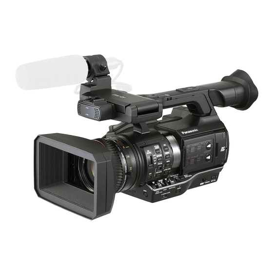
Operating Instructions Memory Card Camera-Recorder AJ-PX270 Model No. Before operating this product, please read the instructions carefully and save this manual for future use. ENGLISH W0214HM6055 -YI VQT5J83A-6(E) -
Page 2: Read This First
Read this first! Read this first! indicates safety information. CAUTION: CAUTION The mains plug of the power supply cord shall RISK OF ELECTRIC SHOCK remain readily operable. DO NOT OPEN The AC receptacle (mains socket outlet) shall be CAUTION: TO REDUCE THE RISK OF ELECTRIC SHOCK, installed near the equipment and shall be easily DO NOT REMOVE COVER (OR BACK). -
Page 3: Declaration Of Conformity
Operation at a voltage other than 120 V AC may require the use of a different AC plug. Please contact either a local or foreign Panasonic authorized service center for assistance in selecting an alternate AC plug. FCC NOTICE (USA) -
Page 4: Important Safety Instructions
Read this first! indicates safety information. NOTIFICATION (Canada) CAN ICES-3(B)/NMB-3(B) The rating plate is on the underside of the Camera Recorder, Battery Charger and AC Adaptor. IMPORTANT SAFETY INSTRUCTIONS 1) Read these instructions. 2) Keep these instructions. 3) Heed all warnings. 4) Follow all instructions. - Page 5 Read this first! Brazil Only Brasil Apenas r Manuseio de baterias usadas BRASIL Após o uso, as pilhas e /ou baterias poderão ser entregues ao estabelecimento comercial ou rede de assistência técnica autorizada. Cobrir os terminais positivo (+) e negativo (-) com uma fita isolante adesiva, antes de depositar numa caixa destinada para o recolhimento.
- Page 6 Batteries that may be used with this product (Correct as of January 2015) Panasonic VW-VBD58 batteries may be used with this product. It has been found that counterfeit battery packs which look very similar to the genuine product are made available to purchase in some markets.
- Page 7 f SDXC logo is a trademark of SD-3C, LLC. f HDMI, HDMI logo, and High-Definition Multimedia Interface are trademarks or registered trademarks of HDMI Licensing LLC in the United States and/ or other countries. f MMC (Multi Media Card) is a registered trademark of Infineon Technologies AG. f Microsoft and Windows are registered trademarks or trademarks of Microsoft Corporation in the United States and/or other countries.
-
Page 8: Table Of Contents
Contents Contents Read this first! Adjusting image quality Detail function Chapter 1 Overview Skin tone function RB gain control function Before using the camera Chroma setting function Use of the camera on a system Matrix function Basic configuration devices Color correction function Expanded configuration devices Black control function What you can do with this camera... - Page 9 Contents Chapter 8 Connecting to External Devices How to use scene file data How to restore the scene file or menu setting status to the Connecting with headphones, remote control, or TV/ factory settings Saving to an SD memory card and loading saved data monitor Selection of external reference signal and generator lock Headphones...
-
Page 10: Chapter 1 Overview
Overview Chapter 1 Before using the camera, read this chapter. For accessories, refer to the leaflet supplied with the product. -
Page 11: Before Using The Camera
Chapter 1 Overview — Before using the camera Before using the camera r When using this product during rain or snow or when at the beach, be careful that water does not get inside the camera recorder. Water causes damage to the camera recorder and memory card. (Repair may be impossible) r Keep the camera recorder away from devices (TVs, TV games, etc.) that produce magnetism. -
Page 12: Before Using The Camera
7 This product includes software licensed under the MOZILLA PUBLIC LICENSE. For details on these descriptions (originally provided in English) and how to obtain the source code, visit the following website. http://pro-av.panasonic.net/ We do not accept inquiries about the details of the source code obtained by the customer. -
Page 13: Use Of The Camera On A System
* For the latest information on P2 cards and SD memory cards that are not described in the Operating Instructions, visit the support desk at the following website: http://pro-av.panasonic.net/ Expanded configuration devices You can also use the following devices in addition to the basic configuration devices. -
Page 14: What You Can Do With This Camera
Chapter 1 Overview — What you can do with this camera What you can do with this camera This camera is a P2 hand-held camera recorder with the following features. f The camera has an optical 22x cam-type zoom and a newly-developed 1/3-type 2.2 million pixel 3MOS sensor with high sensitivity F11 (59.94 Hz)/F12 (50 Hz) and low noise. -
Page 15: Connecting To The Network
Cables are optionally available. They are not supplied with the camera. Use an HDMI cable (optional) with double shielding. For the HDMI cable, using Panasonic HDMI cable is recommended. For the BNC cable (optional) connected to the <SDI OUT> terminal, prepare a double-shielded cable equivalent to 5C-FB. -
Page 16: Chapter 2 Description Of Parts
Description of Parts Chapter 2 This chapter describes the names, functions, and operations of parts on the camera. -
Page 17: Left Side
Chapter 2 Description of Parts — Left side Left side 26 27 13 14 1 Focus ring (page 48) Focus manually when the <FOCUS> switch is set to <M>. 2 Zoom ring (page 55) Adjust the zoom manually when the <ZOOM> switch is set to <MANUAL>. 3 Lens cover switching lever (page 30) Open/close the lens cover. -
Page 18: Left Side
Chapter 2 Description of Parts — Left side 13 <AUTO/MANUAL> switch Select the method to adjust the focus, gain, iris, white balance, and shutter speed at shooting. You can set the function to assign to <AUTO> in the main menu → [AUTO SW]. <AUTO>: Adjust automatically. -
Page 19: Right Side
Make sure that the card has been inserted into the adaptor before use.) - Use of Panasonic SD memory cards and miniSD/microSD cards is recommended. Be sure to format cards on the camera before use. -
Page 20: Right Side
Chapter 2 Description of Parts — Right side 15 <CAM REMOTE> terminal (page 164) Connect the remote control (optional) to control some functions remotely. <FOCUS IRIS>: (3.5 mm mini jack) Control the focus operation and iris operation remotely. <ZOOM S/S>: (2.5 mm mini jack) Control the zoom operation and start/stop operation of recording remotely. 16 Tripod holes Attach the tripod. -
Page 21: Front Side, Rear Side
Chapter 2 Description of Parts — Front side, rear side Front side, rear side 1 Built-in microphone (page 64) This is the built-in stereo microphone. 2 Light sensor Detects indoor and outdoor light. 3 Front tally lamp (page 43) Lights during shooting. This lamp will blink when the battery level becomes low. 4 Recording button (front side) (page 45) Press this button to start recording. - Page 22 Chapter 2 Description of Parts — Front side, rear side 22 <LAN> terminal (page 181) Connect the LAN cable. 23 <DC IN 12V> terminal (page 27) This is the input terminal for the external power supply. Connect the supplied AC adaptor. –...
-
Page 23: Top Side
Chapter 2 Description of Parts — Top side Top side 14 15 16 1 Light shoe Attach the video light. 2 Recording button (handle side) (page 45) Press this button to start recording. Press it again to stop recording. This includes hold mechanism. 3 Zoom lever (grip side) (page 55) Adjust the zoom of an image. - Page 24 Chapter 2 Description of Parts — Top side 14 <(> button This works when the thumbnail screen is displayed. Press this button to stop playback. Press this button when you stop interval recording or one-shot recording, or when you end combining to the clip of one-clip recording. 15 <)>...
-
Page 25: Chapter 3 Preparation
Preparation Chapter 3 Before you use the camera, mount the battery following the procedures in this chapter. The mounting of accessories is also described in this chapter. -
Page 26: Power Supply
Chapter 3 Preparation — Power supply Power supply A battery or AC adaptor can be used as the power supply. Charging the battery The battery is not charged at the time of purchase. Fully charge the battery in the battery charger before using the battery. It is recommended that you have one extra battery. -
Page 27: Attaching And Removing The Battery
Chapter 3 Preparation — Power supply Attaching and removing the battery Attaching Insert the battery until you hear it clicks. Removing Lock release button Power switch Battery release button Turn the power switch to <OFF> while holding down the lock release button. Make sure that the LCD monitor has gone off. - Page 28 Chapter 3 Preparation — Power supply Connect the AC adaptor to the <DC IN 12V> terminal. Removing Turn the power switch to <OFF> while holding down the lock release button. Make sure that the LCD monitor has gone off. Remove the AC adaptor from the <DC IN 12V> terminal. NOTE t When not using the camera, remove the AC cable from the power outlet.
-
Page 29: Attaching And Adjusting Accessories
Chapter 3 Preparation — Attaching and adjusting accessories Attaching and adjusting accessories Adjusting the grip strap Adjust the grip strap so that it fits the size of your hand. Open the cover and adjust the length of the strap. Replace the cover. Attach the cover firmly. -
Page 30: Attaching The Eye Cup
Chapter 3 Preparation — Attaching and adjusting accessories Attaching Center of camera The side with the index of the lens hood Align the index of the lens hood with the center of the camera body and attach. Position the lens hood so that the side with the index of the lens hood is facing upwards. Rotate the lens hood clockwise until it locks in with a click. -
Page 31: Attaching The Front Microphone
Chapter 3 Preparation — Attaching and adjusting accessories Attaching the front microphone Microphones such as a super-directional microphone AG-MC200G (optional) can be attached. Screws for tapped hole protection are attached on the camera body. Remove those screws when you attach the microphone holder. Screw for the microphone holder Microphone cable clamp Microphone holder... -
Page 32: Turning On/Off The Power
Chapter 3 Preparation — Turning on/off the power Turning on/off the power Lock release button Power switch How to turn on the power Align the power switch to <ON> while holding down the lock release button. The LCD monitor lights up. How to turn off the power Align the power switch to <OFF>... -
Page 33: Setting The Date/Time Of The Internal Clock
Chapter 3 Preparation — Setting the date/time of the internal clock Setting the date/time of the internal clock The value of the time is recorded to content (clips) and affects the thumbnail playback order. Before recording, be sure to check and set the date and time zone. -
Page 34: P2 Card
Chapter 3 Preparation — P2 card P2 card Inserting a P2 card When using the camera for the first time, be sure to set the time data beforehand. (page 33) Select and use either of the microP2 or P2 memory card slot on the camera. microP2 memory card slot 1 microP2 memory card access LED Eject button... -
Page 35: Removing A P2 Card
Chapter 3 Preparation — P2 card Removing a P2 card Fig. 1 Fig. 2 Open the card slot cover. Remove the card. f microP2 memory cards - Press in the microP2 card further into the camera and let go. - The microP2 memory card is released from the card slot, and the microP2 memory card can be removed. f P2 memory cards - Lift the eject button (Fig. -
Page 36: P2 Card Recording Time
The driver installed on the camera may be required to be updated depending on the type of P2 card. (page 207) t Refer to our support desk at the following website for the latest information not included in these operating instructions. http://pro-av.panasonic.net/ r P2 card recording times... -
Page 37: Cps (Content Protection System)
Chapter 3 Preparation — P2 card Dividing clips recorded on P2 cards If P2 cards with a capacity of 8 GB or more are used on the camera, recording is automatically continued as another clip when a single continuous recording time exceeds the following times. When thumbnails for clips are handled (displayed, deleted, restored, etc.) on P2 devices, they can be handled as a single clip. - Page 38 “P2 Viewer Plus” software. For details on downloading P2 Viewer Plus and the operating environment, visit the support desk at the following website: http://pro-av.panasonic.net/ t Follow the steps below to use general IT tools such as Microsoft Windows Explorer or Apple Finder to transfer the data to a computer. Be sure to use P2 Viewer Plus to write data back to a P2 card.
-
Page 39: Assigning Functions To The User Buttons
Chapter 3 Preparation — Assigning functions to the USER buttons Assigning functions to the USER buttons Selected functions can be assigned to USER1 to USER8. Set the functions to be assigned to [USER1] to [USER8] in the main menu → [USER SW]. Check the setting details using the <DISP/MODE CHK>... - Page 40 Chapter 3 Preparation — Assigning functions to the USER buttons Item Description [SHOT MARK] Assigns the shot mark function. [DEL LAST CLIP] Assigns the function to delete the clip shot immediately beforehand. [SLOT SEL] Assigns the function for switching the card to record when two or more cards are inserted in the microP2 memory card slot. Assigns the function to select the recording target slot between the P2 memory card slot and microP2 memory card slot.
-
Page 41: Adjusting And Setting The Lcd Monitor
Chapter 3 Preparation — Adjusting and setting the LCD monitor Adjusting and setting the LCD monitor Using the LCD monitor The LCD monitor of this camera is a 3.5 type. Use either the viewfinder or the LCD monitor depending on your purpose and the shooting conditions. Fig. -
Page 42: Adjusting And Setting The Viewfinder
Chapter 3 Preparation — Adjusting and setting the viewfinder Adjusting and setting the viewfinder The viewfinder of this camera is a 0.5 type organic EL. Use either the viewfinder or the LCD monitor depending on your purpose and the shooting conditions. -
Page 43: Tally Lamp
Chapter 3 Preparation — Tally lamp Tally lamp If set to anything other than [OFF] in the main menu → [OTHER FUNCTIONS] → [TALLY LAMP], you can make up the tally lamp light while photographing. Also, the tally lamp will flash when the following situations occur: f When the remaining capacity of the battery is exhausted (four times per second) f The P2 card has less free space to record and the battery level is low (one time per second) f The P2 card has been removed while being accessed (four times per second) -
Page 44: Chapter 4 Shooting
Shooting Chapter 4 This chapter describes the basic procedure for recording. It also describes special shooting methods such as pre-recording and loop recording. -
Page 45: Basic Procedures
Chapter 4 Shooting — Basic procedures Basic procedures This section describes the basic procedures for shooting. When you actually start shooting, pre-inspect your system to ensure that it works properly after making preparations. Preparation Attach the fully charged battery, or connect the AC adaptor. (page 26) Set the power switch to <ON>. -
Page 46: Selecting The Resolution, Codec, And Video Format For Recording
Chapter 4 Shooting — Basic procedures f Returns to recording standby after checking. f For clips within ten seconds, previous clips are not played back even if the <REC CHECK> button is held down after returning to the start of the current clip. -
Page 47: Basic Procedures
Chapter 4 Shooting — Basic procedures r Resolution: 1280×720 Setting Recording format [LINE&FREQ] [REC FORMAT] [CAMERA MODE] [720-60P] [AVC-I200/60P] — 720/60P [AVC-I100/60P] [AVC-I50/60P] [AVC-G50/60P] [AVC-G25/60P] [AVC-G12/60P] [DVCPRO HD/60P] [AVC-I100/30PN] 720/30PN Native [AVC-I100/24PN] 720/24PN Native [720-50P] [AVC-I200/50P] — 720/50P [AVC-I100/50P] [AVC-I50/50P] [AVC-G50/50P] [AVC-G25/50P] [AVC-G12/50P]... -
Page 48: Adjustable Settings When Shooting
Chapter 4 Shooting — Adjustable settings when shooting Adjustable settings when shooting Adjust the iris and gain when shooting. Iris Switch to manual mode with the <AUTO/MANUAL> switch. (page 45) Press the <IRIS> button to switch the adjustment method for the lens aperture. [AUTO IRIS]: Adjusts iris setting automatically. -
Page 49: Focus Assist Function
Chapter 4 Shooting — Adjustable settings when shooting <c>: Changes to the manual focus mode after the focus distance is set to infinity. This switch is the spring switch. Even when the <FOCUS> switch is pushed towards the <c> side, the switch returns to the <M> position. NOTE t Since the auto focus control may not operate properly if there is a flicker, select a shutter speed that is appropriate to the light. -
Page 50: Area Mode Function
Chapter 4 Shooting — Adjustable settings when shooting Focus bar display [FOCUS BAR] The focus bar can be displayed when [ON] is set in the main menu → [DISPLAY SETUP] → [FOCUS BAR]. The degree of focus is indicated by the length of the bar. f White bar: Focus bar display f Green line: Peak display Not in focus... -
Page 51: Level Gauge Function
Chapter 4 Shooting — Adjustable settings when shooting Level gauge function A level gauge that indicates the horizontal and vertical inclinations of the camera recorder can be displayed on the LCD monitor. Horizontal direction Example) When correcting the inclination towards the left Vertical direction Example) When correcting the downward inclination Orange lines will be displayed when inclined. -
Page 52: Adjusting The White And Black Balance
Chapter 4 Shooting — Adjusting the white and black balance Adjusting the white and black balance To obtain high-quality video at all times using the camera, the white and black balance must be adjusted according to conditions. To obtain higher image quality, adjust in the order of AWB (white balance adjustment) → ABB (black balance adjustment) → AWB (white balance adjustment). -
Page 53: Adjusting The Black Balance
Chapter 4 Shooting — Adjusting the white and black balance When you have no time to adjust the white balance Set the <WHITE BAL> switch to <PRST>. f Each time the <AWB> button is pressed, the values set in [3200K], [5600K], and main menu → [SW MODE] → [W.BAL VAR] are toggled in order. When [VAR] is selected, turning the <SEL/PUSH SET>... - Page 54 Chapter 4 Shooting — Adjusting the white and black balance r Messages displayed in the viewfinder and LCD monitor Status Message Remark During adjustment [ABB ACTIVE] f The adjusted value is automatically stored in Adjustment completed [ABB OK] memory. NOTE t During black balance adjustment, the aperture is set to automatically shut out light.
-
Page 55: Using The Zoom Function
Chapter 4 Shooting — Using the zoom function Using the zoom function Adjust the angle of view you want to shoot. The camera has a 22x optical zoom. The zoom can be operated at the following three locations: f Zoom lever (on the grip) f Zoom lever (on the handle) f Zoom ring on the lens Select the zoom operation with the <ZOOM>... -
Page 56: Adjusting Image Quality
Chapter 4 Shooting — Adjusting image quality Adjusting image quality The image quality of the video to be recorded can be set in the main menu → [SCENE FILE]. To change “Advanced settings”, measuring equipment such as vector scope is necessary. Detail function This function thickens or weakens the outlines of images. -
Page 57: Rb Gain Control Function
Chapter 4 Shooting — Adjusting image quality RB gain control function This function makes settings to add or reduce intensity of red and blue colors according to the position of the <WHITE BAL> switch. The function works when the switch is at the <PRST> position or when automatic white balance is active. It does not work when auto tracking white balance is activated. -
Page 58: Color Correction Function
Chapter 4 Shooting — Adjusting image quality Color correction function This function sets color saturation and phase. It applies individual effect on 15 phases in a image. It can be set to individual color hue. Yl-R-R R-R-Mg Yl-R R-Mg Yl-Yl-R [(PHASE)] G-Yl Mg-B... -
Page 59: High Color Function
Chapter 4 Shooting — Adjusting image quality r Advanced settings Configure the settings in the main menu → [SCENE FILE] → [KNEE SETTING]. [KNEE MODE]: Sets the operation mode of knee function ([AUTO]/[MANUAL]/[OFF]). f When [AUTO] is selected in [KNEE SETTING] [A.KNEE RESPONSE]: Sets the speed of response. -
Page 60: Setting The Electronic Shutter
Chapter 4 Shooting — Setting the electronic shutter Setting the electronic shutter Shutter mode The shutter modes available on the electronic shutter of the camera and selectable shutter speeds are as follows. Using a fixed shutter speed f To remove flicker caused by lighting f To shoot fast-moving subjects clearly Using the synchro scan mode f To shoot so that stripe patterns in the horizontal direction are reduced when shooting on the monitor screen... -
Page 61: Flash Band Compensation (Fbc) Function
Chapter 4 Shooting — Flash band compensation (FBC) function Flash band compensation (FBC) function The camera is equipped with a function for compensating and reducing band-like interference (called “flash band”) that occurs due to the MOS pickup device when shooting in environments where flash strobe light such as that from still cameras is present. Change over time Flash firing Shot image... -
Page 62: Variable Frame Rate (Vfr) Recording Function
Chapter 4 Shooting — Variable frame rate (VFR) recording function Variable frame rate (VFR) recording function This camera can shoot quick motion (undercrank) or slow motion (overcrank) video in 1080P and in the AVC-I100 mode. You can select native (PN) recording mode and standard (OVER) recording. In native recording, quick motion and slow motion effects can be obtained without processing recorded images in nonlinear recording system. - Page 63 Chapter 4 Shooting — Variable frame rate (VFR) recording function NOTE t During standard variable frame rate recording, pre-recording, loop recording, interval recording, one-shot recording, dual codec recording, and one-clip recording can not be performed. t Audio can be recorded. t Auto iris, auto focus, and auto tracking white balance do not function when the frame rate is set to [9fps] or lower, or when the shutter speed is set to lower than 1/12.
-
Page 64: Selecting Audio Input And Adjusting Recording Levels
Chapter 4 Shooting — Selecting audio input and adjusting recording levels Selecting audio input and adjusting recording levels The camera supports independent 4-channel sound recording in all recording formats (HD, SD). You can switch audio input recorded on the various channels between the built-in microphone, an external microphone, or a connected audio device. Selecting audio input signals Select the audio signal to be recorded to audio channel 1/2. -
Page 65: Adjusting The Recording Level
Common settings for channels 1 through 4. [20dB]: Select to match to the Panasonic AJ series camera recorder for broadcasting. [12dB]: Select to match to the Panasonic AG-HPX170 series camera recorder for business use. Adjustment with the <F.AUDIO LEVEL> dial Adjust not to reach the excessive input while watching the level meter on the LCD monitor or viewfinder screen. -
Page 66: Getting Position Information Using The Gps
Chapter 4 Shooting — Getting position information using the GPS Getting position information using the GPS The GPS is built-in the camera. You can record the position information using GPS to clips as clip metadata. Information from GPS (latitude, longitude, altitude, date and time) can be viewed on the screen. For details, refer to “Mode check display” (page 161). Set [ON] in the main menu →... -
Page 67: Special Recording Functions
Chapter 4 Shooting — Special recording functions Special recording functions You can use special recording functions such as pre-recording and loop recording by setting the menu. Pre-recording This function enables recording of video and audio from a fixed amount of time (approx. 3 seconds during HD recording, and approx. 7 seconds during SD recording) before recording is actually started. -
Page 68: One-Shot Recording
Chapter 4 Shooting — Special recording functions One-shot recording Recording takes place once for the set amount of time. Set all items in the main menu → [SYSTEM MODE]. Select [ONE SHOT] in the main menu → [RECORDING SETUP] → [RECORDING]. Set the time with [ONE SHOT TIME] in the main menu →... -
Page 69: One-Clip Recording
Chapter 4 Shooting — Special recording functions One-clip recording You can record a single recording (from start to stop of recording) not as one clip but as a clip integrating several recordings. Record start Record start Record start First recording Second recording Nth recording Record stop... -
Page 70: Simultaneous Recording
Refer to the support desk at the following website for the latest information on software whose operability has been confirmed. http://pro-av.panasonic.net/ Simultaneous recording This function records the same image onto two microP2 memory cards when the two microP2 memory cards are inserted into two slots. -
Page 71: Hot Swap Recording
Chapter 4 Shooting — Special recording functions Memory card recording time Recording button operation Button operation for background recording stop* No remaining space on slot 1 REC PAUSE REC STOP Slot 1 (Main recording) A clip Stand-by C clip REC PAUSE Slot 2 A clip B clip... -
Page 72: Recording Check Function
Chapter 4 Shooting — Special recording functions NOTE t You can perform hot swap recording only in the microP2 memory card slot. t Change slots while recording is on stand-by. You cannot change slots during recording. t Hot swap playback is not supported. Recording check function f After recording ends, press the <REC CHECK>... -
Page 73: Convenient Shooting Functions
Chapter 4 Shooting — Convenient shooting functions Convenient shooting functions Low angle shooting When shooting at low angles, releasing the hold cover on the REC button on the handle from the <HOLD> position will allow shooting with the REC button on the handle. f To prevent accidental operation of the REC button on the handle when it is not in use, keep the hold cover to the <HOLD>... -
Page 74: Displaying Frame Marker
Chapter 4 Shooting — Convenient shooting functions NOTE t The safety zone marker display is not displayed in the images of terminals <SDI OUT>, <GENLOCK IN/VIDEO OUT>, and <HDMI OUT>. Displaying frame marker Displays when [ON] is set in the main menu → [DISPLAY SETUP] → [FRAME MARK]. Set the angle of view in the main menu →... -
Page 75: Deleting Last Clip Function
Chapter 4 Shooting — Convenient shooting functions t Date and time is recorded at the lower right of the video. It is different from the position of the date and time displayed in the viewfinder and LCD monitor. Deleting last clip function You can delete the last clip you shot. -
Page 76: Multi Formats
Chapter 4 Shooting — Multi formats Multi formats Selecting recording signals This camera can record HD (1080P, 1080i, 720P) signals in a combined format of AVC-Intra, AVC-LongG, and DVCPRO HD codecs, and can record SD (480i/576i) signals in a combined format of DVCPRO50, DVCPRO, and DV codecs. Recording and shooting signals can be selected in the main menu →... - Page 77 Chapter 4 Shooting — Multi formats System mode Recording function [LINE&FREQ] [REC FORMAT] [CAMERA MODE] [AUDIO SMPL RES] Standard recording Pre-recording Interval recording [AVC-I200/24PN] — [24BIT] — — [AVC-I100/24PN] — — — [1080-23.98PsF] [AVC-G50/24PN] — — — [24BIT]/[16BIT] [AVC-G25/24PN] — —...
- Page 78 Chapter 4 Shooting — Multi formats System mode Recording function [LINE&FREQ] [REC FORMAT] [CAMERA MODE] [AUDIO SMPL RES] One-shot recording Loop recording One-clip recording [AVC-I200/60i] — [24BIT] — — — [AVC-I100/60i] — [24BIT]/[16BIT] [AVC-I50/60i] — [AVC-G50/60i] — — [1080-59.94i] [24BIT] [AVC-G25/60i] —...
- Page 79 Chapter 4 Shooting — Multi formats System mode Recording function Simultaneous [LINE&FREQ] [REC FORMAT] [CAMERA MODE] [AUDIO SMPL RES] Background recording recording [AVC-I200/30PN] — — — [24BIT] [AVC-I200/24PN] — — — [AVC-I100/60P] — — — [AVC-I100/30PN] — [24BIT]/[16BIT] — — [AVC-I100/24PN] —...
- Page 80 Chapter 4 Shooting — Multi formats System mode Recording function Simultaneous [LINE&FREQ] [REC FORMAT] [CAMERA MODE] [AUDIO SMPL RES] Background recording recording [60i] — [DVCPRO50/60i] [30P] — [60i] — [480-59.94i] [DVCPRO/60i] [16BIT] [30P] — [60i] — [DV/60i] [30P] — [50i] —...
-
Page 81: List Of Recording Settings And Recording Functions
Chapter 4 Shooting — Multi formats System mode Recording function Dual codec recording [LINE&FREQ] [REC FORMAT] [CAMERA MODE] [AUDIO SMPL RES] HD proxy* SD proxy* [AVC-I200/60P] — [24BIT] — — [AVC-I100/60P] — [AVC-I100/30PN] — — [24BIT]/[16BIT] [AVC-I100/24PN] — — [720-59.94P] [AVC-I50/60P] —... -
Page 82: Selecting Video Output
Chapter 4 Shooting — Multi formats Selecting video output The video output method can be selected. Video output, etc. can be selected by the setting of [SDI&HDMI SELECT], [3G-SDI OUT], or [DOWNCON MODE] in the main menu → [OUTPUT SEL]. Item Description of settings [SDI&HDMI SELECT]... -
Page 83: Recording/Playback And Output Format List
Chapter 4 Shooting — Multi formats Recording/playback and output format list f Frequencies in signal methods are annotated without fractions. - 59.94 → 60 / 23.98 → 24 / 29.97 → 30 Setting <SDI OUT> terminal Recording [CAMERA format [LINE&FREQ] [REC FORMAT] [VFR] [FRAME RATE]... - Page 84 Chapter 4 Shooting — Multi formats Setting <SDI OUT> terminal Recording [CAMERA format [LINE&FREQ] [REC FORMAT] [VFR] [FRAME RATE] Video format Audio MODE] [60i] 480/60i 480/59.94i [DVCPRO50/60i] [480-59.94i] [DVCPRO/60i] Disabled Disabled 480/30P over 60i 480/29.97PsF [30P] [DV/60i] 2:2 Pull Down over 59.94i 2:2 [50i] 576/50i...
-
Page 85: Dual Codec Recording
Chapter 4 Shooting — Dual codec recording Dual codec recording Recording in different formats for main recording and sub recording can be performed on the camera. For sub recording, you can select HD proxy in AVC-LongG 6 format with 1920×1080 resolution or one of three SD proxies with different resolution. The file format is MOV that is suitable for nonlinear editing. -
Page 86: Recording The Proxy Data
Approx. 1650 kbps Approx. 78 min [LOW 2CH MOV] Approx. 950 kbps Approx. 135 min (These are reference values for continuous recording with Panasonic products. The recording time may differ depending on the scene or the number of clips) – 86 –... -
Page 87: Checking The Proxy Data
Use P2 Viewer Plus to check the proxy data. Some versions of P2 Viewer Plus may not be able to check the data. For information on P2 Viewer Plus, visit the following website: http://pro-av.panasonic.net/ NOTE t Clips with proxy data recorded with the camera are handled as unknown clips by some P2 devices. - Page 88 Chapter 4 Shooting — Dual codec recording Error displays Behavior and cause Action to take (viewfinder screen) [SD 0 min] Recording of the materials and proxy data will continue. After finishing recording, insert a new SD memory card. f The remaining SD memory card capacity is getting low. (approximately shorter than one minute) [SD END] Proxy data recording to the SD memory card will stop, but...
-
Page 89: Streaming Function
For details on downloading application software which supports video streaming and the operating environment, visit the support desk at the following website: http://pro-av.panasonic.net/ t The streaming function cannot be used together with the dual codec recording, simultaneous recording, and background recording. -
Page 90: List Of Streaming Modes And Resolution/Frame Rates
Chapter 4 Shooting — Streaming function [SYSTEM MODE] [STREAMING MODE] HD streaming SD streaming [LINE&FREQ] [REC FORMAT] [AVC-G6], [AVC-G (QoS)] [HQ], [LOW], [SHQ (QoS)] [AVC-I100/50i] [AVC-I50/50i] — [1080-50i] [AVC-G50/50i] [AVC-G25/50i] [AVC-I100/60P] [AVC-I50/60P] — [720-59.94P] [AVC-G50/60P] [AVC-G25/60P] [AVC-I100/50P] [AVC-I50/50P] — [720-50P] [AVC-G50/50P] [AVC-G25/50P] * [LOW] cannot be selected. -
Page 91: Handling Setting Data
Chapter 4 Shooting — Handling setting data Handling setting data Setting data file configuration Scene files with [F1:] to [F6:] can be saved on the camera according to the settings in the main menu → [SCENE FILE]. Scene file data ([F1:] to [F6:]) can be saved as a file, and up to eight files can be saved on the SD memory card at a time, which can be loaded and used. -
Page 92: Performing Operations On Sd Memory Cards
Chapter 4 Shooting — Handling setting data Inserting SD memory cards Fig. 1 Fig. 2 Open the slot cover. (Fig. 1) Insert the SD memory card into the SD memory card slot with the label side of the card upward, and close the slot cover. (Fig. 2) NOTE t The SD memory card must be inserted with the correct side facing the SD card slot. -
Page 93: How To Use User Data
Chapter 4 Shooting — Handling setting data Select [YES] in the confirmation screen and press the control stick (or <SEL/PUSH SET> dial button). (Fig. 1) Not to format the memory card, select [NO] and press the control stick (or <SEL/PUSH SET> dial button). When the completion message is displayed, select [OK] and press the control stick (or <SEL/PUSH SET>... - Page 94 Chapter 4 Shooting — Handling setting data Saving scene file setting data to the camera memory Fig. 1 Select the file to be saved in the main menu → [SCENE FILE] → [FILE SELECT] and press the control stick (or <SEL/PUSH SET> dial button).
-
Page 95: How To Restore The Scene File Or Menu Setting Status To The Factory Settings
Chapter 4 Shooting — Handling setting data How to restore the scene file or menu setting status to the factory settings All the scene files and menu settings of the camera can be collectively restored to the factory settings. Select [MENU INITIALIZE] in the main menu → [OTHER FUNCTIONS] and press the control stick (or <SEL/PUSH SET> dial button). -
Page 96: Selection Of External Reference Signal And Generator Lock Setting
Chapter 4 Shooting — Selection of external reference signal and generator lock setting Selection of external reference signal and generator lock setting Locking the video signal to the external reference signal The video signal output from the camera can be locked to the reference signal supplied from an external source. The camera can receive external reference signals from the <GENLOCK IN/VIDEO OUT>... -
Page 97: Setting The Time Data
Chapter 4 Shooting — Setting the time data Setting the time data The camera provides time codes, user bits, and date and time (real time) data as time data, and they are recorded in the frame in sync with video. They are also recorded as data for clip metadata files. - Page 98 Chapter 4 Shooting — Setting the time data Setting Recording TC [LINE&FREQ] [REC FORMAT] [CAMERA MODE] [FRAME RATE] VITC [AVC-I100/50P] Recording run/free run* [AVC-G25/50P] — 25 frames [AVC-G12/50P] [AVC-I200/25PN] [AVC-G50/25PN] Recording run/free run* — [AVC-G25/25PN] 25 frames [1080-50P] — Same value as LTC [AVC-G12/25PN] Recording run/free run* [25fps]...
- Page 99 Chapter 4 Shooting — Setting the time data Setting Output TC [LINE&FREQ] [REC FORMAT] [CAMERA MODE] [FRAME RATE] TC OUT LTC, VITC of HD SDI [AVC-I200/60i] [AVC-I100/60i] [AVC-I50/60i] — — [AVC-G50/60i] [1080-59.94i] LTC is output. LTC is output. [AVC-G25/60i] [AVC-G12/60i] [DVCPRO HD/60i] —...
- Page 100 Chapter 4 Shooting — Setting the time data Recording of user bits Setting Recording UB [LINE&FREQ] [REC FORMAT] [CAMERA MODE] [FRAME RATE] LTC UB VITC UB [AVC-I100/60P] Follows [VITC UBG [AVC-G25/60P] — MODE]. [AVC-G12/60P] [AVC-I200/30PN] [AVC-G50/30PN] — [AVC-G25/30PN] [AVC-G12/30PN] [30fps] [1080-59.94P] —...
- Page 101 Chapter 4 Shooting — Setting the time data Output of user bits Setting Output UB [LINE&FREQ] [REC FORMAT] [CAMERA MODE] [FRAME RATE] UB for TC OUT LTC UB for HD SDI VITC UB for HD SDI [AVC-I100/60P] [AVC-G25/60P] — [AVC-G12/60P] [AVC-I200/30PN] [AVC-G50/30PN] LTC UB is output.
-
Page 102: User Bits Settings
Chapter 4 Shooting — Setting the time data User bits settings Sets the user bits to be recorded in the sub code area in the main menu → [RECORDING SETUP] → [UBG MODE]. Item Description [USER] Records internal user values. You can set the user value in the main menu → [RECORDING SETUP] → [UB PRESET]. Setting values are held even when the power is turned off. -
Page 103: Setting The Time Code
Chapter 4 Shooting — Setting the time data Verification information on the right-hand six digits Media management information ・ Updated frame flags and valid frame flags Fixed values ・ REC mark Sequence No. 24P: 0-4 Other than above: F-fixed Camera image mode ・60i:600 Example) ・60P:608... -
Page 104: Externally Locking The Time Code
Chapter 4 Shooting — Setting the time data f It is the same when shooting in modes other than 30P when in 30PN and shooting in modes other than 25P when in 25PN. Externally locking the time code The internal time code generator of the camera can be locked to an external generator. In addition, the time code generator of an external device can be locked to the internal time code generator of the camera. -
Page 105: Supplying The Time Code Externally
Chapter 4 Shooting — Setting the time data External lock operation procedure To externally lock the time code, follow the steps below. Set [FREE RUN] in the main menu → [RECORDING SETUP] → [TCG]. Display TC with the <COUNTER> button. Input a reference time code and reference video signal that are in a phase relationship (that conforms to time code specifications) to the <TC IN/OUT>... -
Page 106: Connecting And Setting The Genlock And Time Code Input/Output
Chapter 4 Shooting — Setting the time data Set [TCG/TCR] in the main menu → [OUTPUT SEL] → [TC OUT]. NOTE t If you set [TC OUTPUT REF] to [VIDEO OUT] in the main menu → [OUTPUT SEL], the input time code will be output to match the video output delay. Connecting and setting the genlock and time code input/output The relationship of the connecting and settings between the genlock and time code input/output is shown in the table. -
Page 107: Chapter 5 Playback
Playback Chapter 5 Data including additional information such as images, audio, text memo, and metadata that are created from one shooting are saved as a clip. You can play back and edit clips with the camera. -
Page 108: Basic Procedures
Chapter 5 Playback — Basic procedures Basic procedures Preparation Connect the battery or AC adaptor. (page 26) Set the power switch to <ON>. (page 32) Open the LCD monitor. Playback a: <THUMBNAIL> button b: <=/&> button c: Control stick Press the <THUMBNAIL> button. The thumbnail screen appears on the viewfinder screen. -
Page 109: Thumbnail Operations
Chapter 5 Playback — Thumbnail operations Thumbnail operations Thumbnail operation overview A clip is a group of data created from one shooting session, which includes additional information such as images, audio, text memo, and metadata that are created from one shooting. The following operations can be performed while viewing the clip thumbnails displayed on the LCD monitor. - Page 110 Chapter 5 Playback — Thumbnail operations Displayed in yellow while the wired LAN is active. (Yellow) Displayed in red when there is a problem with the connection status of wired LAN. (Red) Displayed in gray when the wireless LAN is not activated properly. (Gray) Displayed in white when the wireless LAN is not connected.
-
Page 111: Selecting Thumbnails
Chapter 5 Playback — Thumbnail operations Text memo indicator Displayed for clips with text memo data attached. Edit copied clip indicator Displayed for the edit copied clip. Wide clip indicator Displayed for clips recorded with the 16:9 aspect ratio. However, it does not accompany clips in HD format. Incomplete clip indicator Displayed when clips are saved across multiple P2 cards and either of the P2 cards is not inserted in a card slot. -
Page 112: Setting Thumbnail Screen Display
Chapter 5 Playback — Thumbnail operations Setting thumbnail screen display You can customize the thumbnail screen according to usage. Setting example for thumbnail screen ([INDICATOR]) Select [THUMBNAIL SETUP] in the main menu → [CLIP]. The thumbnail setting items ([INDICATOR], [DATA DISPLAY], [THUMBNAIL SIZE], [PB POSITION], [PROPERTY DISP.]) are displayed. For details, refer to “Setting items that display properties”... -
Page 113: Changing Thumbnails
Chapter 5 Playback — Thumbnail operations Select [PROPERTY DISP.] in the main menu → [CLIP] → [THUMBNAIL SETUP]. Press the control stick to enter the item menu. (Fig. 2) The selected item has a check mark on it. Press the control stick. Pressing the control stick will check unchecked items, and uncheck the checked items. - Page 114 Chapter 5 Playback — Thumbnail operations Adding the text memo You must assign [TEXT MEMO] to the USER button (USER1 to USER8) beforehand. For details, refer to “Assigning functions to the USER buttons” (page 39). Press the USER button to which [TEXT MEMO] is assigned while recording, playback, thumbnails. f Pressing this button while recording or playing inserts a text memo at the instance when the button was pressed.
-
Page 115: Deleting Clips
Chapter 5 Playback — Thumbnail operations Move the cursor over the text memo to be copied and press the control stick. You can select multiple text memos. Select [COPY] in the main menu → [CLIP]. Select the copy target slot using the control stick and select [YES]. f Copying starts. -
Page 116: Setting Clip Metadata
Using the latest update version of P2 Viewer Plus, metadata upload files can be written to SD memory cards using a computer. Download and install the latest version of P2 Viewer Plus from the following website. http://pro-av.panasonic.net/ For details on SD memory cards to be used, refer to “Cautions when using SD memory cards” (page 19). - Page 117 Chapter 5 Playback — Thumbnail operations Loading clip metadata (metadata upload) Fig. 1 Fig. 2 Insert the SD memory card that contains the clip metadata (metadata upload file). Select [LOAD] in the main menu → [RECORDING SETUP] → [REC META DATA] and press the control stick. The metadata name of the metadata upload file on the SD memory card is displayed.
-
Page 118: Formatting A P2 Card
Chapter 5 Playback — Thumbnail operations Status of clip metadata [USER CLIP NAME] to be recorded When no clip metadata has been loaded, or when setting disables recording of loaded clip Same as [GLOBAL CLIP ID] metadata r [TYPE2] Status of clip metadata [USER CLIP NAME] to be recorded When clip metadata has been loaded Uploaded data + [COUNT] value*... -
Page 119: Properties
Chapter 5 Playback — Thumbnail operations f Select [SD CARD] and press the control stick. f Select [EXIT] when you do not wish to format the card. Select [YES] using the control stick. The SD memory card is formatted. NOTE t SD memory cards can also be formatted in the main menu →... - Page 120 Chapter 5 Playback — Thumbnail operations Modifying recorded clip metadata Fig. 1 Fig. 2 Display the metadata details window for the clip to be modified on the clip properties screen. Place the cursor on the item to be modified using the control stick. (Fig. 1) The items of the metadata with the gray buttons in background can be modified.
- Page 121 Chapter 5 Playback — Thumbnail operations Contents of P2 card status display settings Select [CARD STATUS] in the main menu → [CLIP] → [PROPERTY]. r When [REMAIN] is selected r When [USED] is selected Fig. 1 Fig. 2 1 Write-protected mark mark appears when the P2 card is write-protected.
- Page 122 Chapter 5 Playback — Thumbnail operations The warning can be checked on the P2 card detailed information in “P2 card status (remaining capacity)” (page 121). (Fig. 2) 4 Total slot memory remaining capacity (or used capacity) This displays the total remaining memory capacity (or used capacity) of the three slots. The available space of a write-protected P2 card is not included in the total available space.
-
Page 123: Sd Memory Card Status Display
Manual authentication is valid temporarily. If the target microP2 card is removed or power is turned off, the CPS password set manually is disabled. t Visit the following website for conditions where manual authentication is valid. http://pro-av.panasonic.net/ t The encrypted microP2 memory card is not recognized on the SD card slot in a computer. -
Page 124: Chapter 6 Menu Operations
Menu Operations Chapter 6 This chapter describes how to operate the camera menus, the structure, and details of the setting menu. -
Page 125: Setting Menu Structure
Chapter 6 Menu Operations — Setting menu structure Setting menu structure Menu types and how to open them Menu type How to open [USER MENU] In the main menu → [USER MENU SEL], you can select Displayed by pressing the <MENU> button. the desired items and pages and register to [USER MENU]. -
Page 126: Setting Menu Display
Chapter 6 Menu Operations — Setting menu display Setting menu display Setting menu basic operations You can change camera settings using the setting menu according to the shooting scene and recording details. The menu is divided into the main menu, submenu, and setting item menu. Set data are written and saved in the internal memory of the camera. -
Page 127: Setting [User Menu]
Chapter 6 Menu Operations — Setting menu display f The confirmation screen is displayed depending on the menu item. Press the control stick upward/downward/to the left/to the right to select the operation, and then press the control stick. A checkmark is placed in front of the set item. f In some menus, a screen for setting value is displayed on the menu screen (Fig. - Page 128 Chapter 6 Menu Operations — Setting menu display Initializing user file and all scene files simultaneously Select the main menu → [OTHER FUNCTIONS] → [MENU INITIALIZE]. Select [YES]. – 128 –...
-
Page 129: Menu List
Chapter 6 Menu Operations — Menu list Menu list [SCENE FILE] Configure the settings regarding scene files. This menu is used to set fine image quality settings of the camera images, select scene files, and read/write scene file data to the internal memory. These menu items cannot be set when the thumbnail screen is displayed. - Page 130 Chapter 6 Menu Operations — Menu list Item Description of settings [SKIN TONE DTL A] Selects the skin tone table that will display the skin tone detail. Create the skin tone table with [DETECT TABLE]. You can shoot smoother skin tones by displaying the skin tone detail.
- Page 131 Chapter 6 Menu Operations — Menu list Item Description of settings [COLOR TEMP Ach [COLOR TEMP] Displays the color temperature when the <WHITE BAL> switch is at the <A> position and automatic white SETTING] balance is working, or when it is preset. Also, in automatic white balance operation, the color temperature can be changed by changing the output balance of Rch and Bch.
- Page 132 Chapter 6 Menu Operations — Menu list Item Description of settings [R-R-Mg (SAT)] Corrects the color saturation between red and “colors between red and magenta”. [−63]…[63] f Factory setting: [0] [R-R-Mg (PHASE)] Corrects the hue between red and “colors between red and magenta”. [−63]…[63] f Factory setting: [0] [R-Mg (SAT)]...
- Page 133 Chapter 6 Menu Operations — Menu list Item Description of settings [Yl-R (SAT)] Corrects the color saturation between yellow and red. [−63]…[63] f Factory setting: [0] [Yl-R (PHASE)] Corrects the hue between yellow and red. [−63]…[63] f Factory setting: [0] [Yl-R-R (SAT)] Corrects the color saturation between “colors between yellow and red”...
-
Page 134: [System Mode]
Chapter 6 Menu Operations — Menu list Item Description of settings [KNEE MASTER POINT] Sets the knee point position in 0.5% steps. [70.0%]…[107.0%] f Factory setting: [93.0%] [KNEE MASTER Sets the knee inclination. SLOPE] [0]…[99] f Factory setting: [85] [KNEE MASTER SLOPE Sets the knee inclination of Rch. -
Page 135: [User Sw]
Chapter 6 Menu Operations — Menu list Item Description of settings [SCAN REVERSE] Enables/disables the scan reverse shooting function for vertical/horizontal inversion of images. [ON], [OFF] f Factory setting: [OFF] [SETUP] Sets the setup level of 480i video signals. [0%], [7.5%A] [SHOOTING MODE] Sets the shooting mode according to the shooting environment. -
Page 136: [Sw Mode]
Chapter 6 Menu Operations — Menu list Item Description of settings [USER8] Sets the function to be assigned to the <IRIS> button. [INHIBIT], [SCENE FILE SEL], [LEVEL GAUGE], [LEVEL GAUGE RESET], [WFM], [D.ZOOM], [DRS], [FBC], [S.GAIN], [1S.EXP.], [ATW], [ATW LOCK], [SPOTLIGHT], [BACKLIGHT], [BLACKFADE], [WHITEFADE], [A.IRIS LEVEL], [IRIS], [Y GET], [FOCUS ASSIST], [FOCUS MACRO], [OIS], [FAST ZOOM], [ZEBRA], [EVF ON/OFF], [PRE REC], [TEXT MEMO], [SHOT MARK], [DEL LAST CLIP], [SLOT SEL], [REC MEDIA], [AUDIO MON SEL], [REC CHECK], [BACKGR REC PAUSE], [USB... -
Page 137: [Auto Sw]
Chapter 6 Menu Operations — Menu list Item Description of settings [FOCUS ASSIST MODE] Sets the operation mode of the focus assist function. [EXPAND]: Expands the center part of the screen of the LCD monitor. [IN RED]: Outlines the contour of the video in red. f Factory setting: [EXPAND] If functions are assigned to the USER buttons, on and off of the function can be switched using the USER button operations. -
Page 138: [Recording Setup]
Chapter 6 Menu Operations — Menu list Item Description of settings [AGC] Sets the auto gain control operations when [ON] is selected in [A.IRIS]. [ON]: Performs the operation of the [AGC] function that automatically adjusts camera gain when in auto mode. - Page 139 Chapter 6 Menu Operations — Menu list Item Description of settings [START DELAY] Selects whether to delay the recording start time by approximately one second when performing interval recording or one-short recording. [ON], [OFF] f Factory setting: [OFF] [PRE REC] Selects whether to perform pre-recording.
-
Page 140: [Clip]
Chapter 6 Menu Operations — Menu list Item Description of settings [UBG MODE] Selects the user bits mode. [USER]: Selects the user bits value that has been set. [TIME]: Selects the local time. (hh, mm, ss) [DATE]: Selects the local date and time. (YY, MM, DD, hh) [EXT]: Records the user bits values currently input to the <TC IN/OUT>... - Page 141 Chapter 6 Menu Operations — Menu list Item Description of settings [COPY] Copies the selected clip to a P2 card in any card slot or a storage device. [SLOT 1], [SLOT 2], [SLOT 3], [SD CARD], [STORAGE], [FTP], [FTP(PROXY)] [EXPORT] Exports (writes) from the P2 card or SD memory card to a storage device or FTP by units of card.
-
Page 142: [Audio Setup]
Chapter 6 Menu Operations — Menu list Item Description of settings [PROPERTY DISP.] Sets simple properties item displayed on the left of the thumbnail when [SMALL] is selected for [THUMBNAIL SIZE]. [USER CLIP NAME]: Displays the user clip name. [START TC]: Displays the start time code. [REC DATE]: Displays the recorded date. -
Page 143: [Output Sel]
Chapter 6 Menu Operations — Menu list Item Description of settings [RECORDING CH [FRONT VR SELECT] Sets the allocation to the <F.AUDIO LEVEL> dial. Enabled when the setting is other than <AUTO>. SETTING] [0dB] to [−c] can be adjusted. [CH1], [CH2], [CH3], [CH4], [CH1/CH2], [CH3/CH4], [ALL], [OFF] f Factory setting: [OFF] [AUTO LEVEL CH3] Selects the level setting method for audio channel 3. -
Page 144: [Network Setup]
Chapter 6 Menu Operations — Menu list Item Description of settings [SDI OUT CHAR] Selects whether to superimpose characters on <SDI OUT> terminal output images. [ON]: Superimposes. [OFF]: Does not superimpose. f Factory setting: [OFF] [SDI EDH] Selects whether to superimpose EDH when output from the <SDI OUT> terminal is SD signal (480i and 576i). - Page 145 Chapter 6 Menu Operations — Menu list Item Description of settings [NETWORK SEL] Sets the connection method when connecting the camera with an external device (such as a computer) via network. [WLAN]: Connects via wireless LAN. [4G/LTE]: Connects via 3G/4G/LTE. [LAN]: Connects via the <LAN>...
- Page 146 Chapter 6 Menu Operations — Menu list Item Description of settings [START] When [CAMERA] is selected in [START TRIGGER], the streaming distribution is started/stopped from the camera. [ON]: Starts streaming. [OFF]: Stops streaming. [LAN PROPERTY] [MAC ADDRESS] Displays the MAC address of the <LAN> terminal on the camera. (Cannot be changed.) [DHCP] Sets whether to use automatic acquisition via DHCP.
-
Page 147: [Display Setup]
Chapter 6 Menu Operations — Menu list Item Description of settings [DHCP SERVER] Sets whether to use the DHCP SERVER function when [DIRECT] is selected in [TYPE] and the camera is connected via wireless LAN. [ENABLE]: Uses the DHCP SERVER function. [DISABLE]: Does not use the DHCP SERVER function. - Page 148 Chapter 6 Menu Operations — Menu list Item Description of settings [DATE/TIME] Sets date and time display. [TIME]: Displays the hour, minute, and second. [DATE]: Displays the year, month, and date. [TIME&DATE]: Displays the hour, minute, and second, as well as year, month, and date. [OFF]: Does not display.
- Page 149 Chapter 6 Menu Operations — Menu list Item Description of settings [SYSTEM MODE] Displays/hides system mode. [ON], [OFF] f Factory setting: [OFF] [REC FORMAT] Displays/hides recording format display. [ON], [OFF] f Factory setting: [ON] [FRAME RATE] Displays/hides frame rate. [ON], [OFF] f Factory setting: [ON] [ASPECT] Displays/hides letterbox recording display.
-
Page 150: [Card Functions]
Chapter 6 Menu Operations — Menu list [CARD FUNCTIONS] Configure the settings regarding reading/writing of the scene files and user files to SD memory cards. Item Description of settings [SCENE FILE] Loads scene files from an SD memory card or saves them to an SD memory card. [LOAD]: Loads scene files. -
Page 151: [User Menu Sel]
Chapter 6 Menu Operations — Menu list Item Description of settings [VERSION] Displays the information of the camera. [MODEL NAME]: Displays the product name of the camera. [SERIAL NO.]: Displays the serial number of the camera. [NETWORK ID]: Displays the network ID of the camera. [UID]: Displays the unique ID of the camera. -
Page 152: [Option Menu] List
Chapter 6 Menu Operations — [OPTION MENU] list [OPTION MENU] list [AREA SELECT] Before you use the camera, select a region in which you use the camera. [NTSC]: Select an NTSC region other than Japan. [NTSC (J)]: Select Japan. [PAL]: Select a PAL region. [AWB PRE CONTROL] Change the output display or output value for the white balance preset value [3200K]. -
Page 153: Chapter 7 Display
Display Chapter 7 This chapter describes the screen displayed on the viewfinder or LCD monitor. -
Page 154: Screen Status Display
Chapter 7 Display — Screen status display Screen status display In addition to video, the viewfinder and LCD monitor display messages that indicate the camera settings and operation status, a center marker, safety zone marker, zebra patterns, and other information. Configuration of status display on screen The screen displayed in normal status is displayed as shown below. - Page 155 Chapter 7 Display — Screen status display f [CLIP]: Clip counter value (recording mode only) Clip counter value for each recording Displayed when [CLIP] is set in the main menu → [DISPLAY SETUP] → [REC COUNTER]. f [TCG]: Time code value When operating in drop frame mode, the “:”...
- Page 156 Chapter 7 Display — Screen status display f [LAN]: When the wired LAN is connected (link state) f [LAN ]: When the wired LAN is not connected (unlinked state), or when there is a problem f No display: When the network function is disabled 10 Remote control display in an IP connection The remote control status in an IP connection is displayed when [IP REMOTE] is set to [ENABLE] in the main menu →...
- Page 157 Chapter 7 Display — Screen status display 26 Focus control information display Displays the focus control information with [99] to [00]. [AF] is indicated for auto focus, and [MF] is indicated for manual focus. Also, when [MF ASSIST] is set to [ON] in the main menu → [SW MODE] while in manual focus mode, [MA] is indicated. [95] (distance to the subject: infinity) to [00] (distance to the subject: approx.
-
Page 158: Camera Status Display
Chapter 7 Display — Screen status display f [CLIP&T&=] ([CLIP&T~&]): Cueing up (rewinding) by clip and text memo (when [CLIP&TEXT MEMO] is set in the main menu → [OTHER FUNCTIONS] → [SEEK POS SEL]) f [START]* : Displayed when recording of a new clip is started in one-clip recording. f [END]* : Displayed when combining of clips is ended in one-clip recording. -
Page 159: Checking And Displaying Shooting Status
Chapter 7 Display — Screen status display Checking and displaying shooting status Also, the mode check [STATUS] screen is displayed when the <DISP/MODE CHK> switch is pushed towards the <CHK> side. During mode check, almost all items are displayed including usually hidden items so that the shooting status can be checked. For details on the mode check, refer to “Mode check display”... - Page 160 Chapter 7 Display — Screen status display <DISP/MODE CHK>: <ON> <DISP/ <DISP/MODE Item Shooting Playback MODE CHK>: [OTHER DISPLAY] CHK>: <OFF> <CHK> [ALL] [PARTIAL] [USER] Rec during upload function status — — —* —* —* display 45 GPS display — —...
-
Page 161: Mode Check Display
Chapter 7 Display — Screen status display Mode check display The camera settings and status can be displayed on the viewfinder or LCD monitor screen for check. Each time the <DISP/MODE CHK> switch on the camera is pushed towards the <CHK> side, the five screens are switched. [STATUS] screen display →... - Page 162 Chapter 7 Display — Screen status display [USER SW] screen Displays the assignment status of each USER button. For details, refer to “Assigning functions to the USER buttons” (page 39). [OTHER ASSIGN] [GAIN L] Displays the gain value assigned to <L> of the <GAIN> switch. [GAIN M] Displays the gain value assigned to <M>...
-
Page 163: Chapter 8 Connecting To External Devices
Connecting to External Devices Chapter 8 This chapter describes the external devices that can be connected to the camera. -
Page 164: Connecting With Headphones, Remote Control, Or Tv/Monitor
Chapter 8 Connecting to External Devices — Connecting with headphones, remote control, or TV/monitor Connecting with headphones, remote control, or TV/monitor Headphones Headphones (optional) can be connected to the headphone terminal (3.5 mm stereo mini jack). Headphone terminal NOTE t When headphones are connected, audio is not output from the speaker. Remote control Remote control (optional) can be connected to the <CAM REMOTE>... - Page 165 For the BNC cable (optional) connected to the <SDI OUT> terminal, prepare a double-shielded cable equivalent to 5C-FB. t Prepare the HDMI cable (optional) with double shielded. For the HDMI cable, using Panasonic HDMI cable is recommended. – 165 –...
-
Page 166: Connection Function Via
For the latest information on the driver, visit the following website. http://pro-av.panasonic.net/ t The camera supports only USB 2.0. Ensure your computer supports USB 2.0. t When connecting the camera to a computer via USB, ensure that no other device is connected to the computer via USB.Or -
Page 167: Switching To The Usb Host Mode
Chapter 8 Connecting to External Devices — Connection function via <USB2.0 DEVICE> or <USB3.0 HOST> terminal Switching to the USB host mode USB cable (optional) External storage device Fig. 1 Fig. 2 Fig. 3 Connect the storage device to the <USB3.0 HOST> terminal. (Fig. 1) f When connecting a storage device which supports USB 3.0, use a cable that conforms to the USB 3.0 standard. - Page 168 Use a storage device with sufficient capacity for copying. t Because the storage device is very sensitive, reading, and writing data may become invalid depending on your usage. Please note that Panasonic has no responsibility for data loss caused from a storage device failure or other defects and any direct or indirect damage related to these.
- Page 169 Chapter 8 Connecting to External Devices — Connection function via <USB2.0 DEVICE> or <USB3.0 HOST> terminal Formatting a storage device You can initialize the storage device to a usable format using the [TYPE S] or the [FAT] file system. Fig. 1 Select [STORAGE] in the main menu →...
- Page 170 Chapter 8 Connecting to External Devices — Connection function via <USB2.0 DEVICE> or <USB3.0 HOST> terminal Move the cursor to the card slot number of the copy source and press the control stick. For [TYPE S], selecting [ALL SLOT] exports all cards currently inserted. Select [YES] in the confirmation message and press the control stick.
- Page 171 Chapter 8 Connecting to External Devices — Connection function via <USB2.0 DEVICE> or <USB3.0 HOST> terminal [MODEL] Model name [SIZE] Total capacity (unit: GB) Used capacity (unit: GB) [USED] Used P2 card area (unit: number of clips), maximum of 23 [FREE CAP.] Remaining capacity (unit: GB) [SELECTED PART.]...
- Page 172 Chapter 8 Connecting to External Devices — Connection function via <USB2.0 DEVICE> or <USB3.0 HOST> terminal NOTE t In [TYPE S] storage devices, [MODEL] is [UNKNOWN] and clips recorded across other partitions will not be one normal clip. Copying clips to a [TYPE S] storage device changes the partition of the copy destination [MODEL] to [UNKNOWN].
- Page 173 Chapter 8 Connecting to External Devices — Connection function via <USB2.0 DEVICE> or <USB3.0 HOST> terminal r Information display items 1 Storage device information For [TYPE S] [SERIAL] P2 card serial number [MODEL] P2 card model name [SELECTED PART.] Displays a checkmark when a target partition is selected [SELECTED PART.
- Page 174 Chapter 8 Connecting to External Devices — Connection function via <USB2.0 DEVICE> or <USB3.0 HOST> terminal Writing back to the P2 card from a storage device (import) Importing from a [TYPE S] storage device or [P2STORE] by partition You can import (write back to a P2 card from as storage device) to a P2 card with the same part number as the source card by partition (card). Insert a P2 card that will serve as the input destination.
-
Page 175: Connecting To The Remote Operation Panel (Ak-Hrp200G)
Chapter 8 Connecting to External Devices — Connecting to the remote operation panel (AK-HRP200G) Connecting to the remote operation panel (AK-HRP200G) f You can remotely control some functions by connecting the remote operation panel AK-HRP200G (optional) via an IP connection. f When you connect AK-HRP200G using a LAN cable and perform network settings of the camera and the AK-HRP200G, the camera automatically enters the remote control mode. - Page 176 Chapter 8 Connecting to External Devices — Connecting to the remote operation panel (AK-HRP200G) r Character/menu button (<CHARA/MENU>) The status and menu are displayed in the output image from the <SDI OUT>, <HDMI OUT>, and <GENLOCK IN/VIDEO OUT> terminals regardless of camera’s menu setting value.
-
Page 177: Connecting To P2 Rop Application
Chapter 8 Connecting to External Devices — Connecting to P2 ROP application Connecting to P2 ROP application Using a P2 ROP application that operates on an iPad connected to the camera via wireless LAN, you can remotely control some functions of the camera. -
Page 178: Chapter 9 Network Connection
Network Connection Chapter 9 This chapter describes how to use the camera by connecting to network. -
Page 179: Network Connection
The camera can be connected to the network via wireless LAN, wired LAN, or 4G/LTE. For details on wireless modules that can be connected, visit the support desk at the following website: http://pro-av.panasonic.net/ To use wireless LAN, attach AJ-WM30 (optional) to the <USB2.0 HOST> terminal. -
Page 180: Preparing For Connection
Chapter 9 Network Connection — Preparing for connection Preparing for connection When using wireless module AJ-WM30 Connect the wireless module AJ-WM30 (optional) to the camera. The grip belt can be removed. <OPEN> button <USB2.0 HOST> terminal Fig. 1 Fig. 2 Press the <OPEN>... -
Page 181: For Wireless Module Other Than Aj-Wm30
Connect the wireless module. (Fig. 6) The wireless module can be stored in the grip belt. NOTE t For details on wireless modules that can be connected, refer to the support desk at the following website. http://pro-av.panasonic.net/en/sales_o/p2/server/4glte.html http://pro-av.panasonic.net/en/sales_o/p2/server/wireless_module.html For wired LAN Connect a LAN cable. -
Page 182: Network Settings
[MAC ADDRESS]: MAC address of wireless LAN (cannot be changed) [SSID]: Network name of the camera (SSID) (Factory setting: [AJ-PX270]) [BAND]: Setting that switches between 2 transmission methods (2.4 GHz or 5 GHz) (Factory setting: [2.4GHz]) (When using AJ-WM30, set this to [2.4GHz]) - Page 183 Chapter 9 Network Connection — Network settings [PRIMARY DNS]: Primary DNS server setting (Factory setting: [0.0.0.0]) (When [DHCP] is set to [ENABLE] and can be acquired from the DNS server, the DNS server value which is acquired externally is overwritten. When the value is [0.0.0.0], the server is not set.) [SECONDARY DNS]: Secondary DNS server setting (Factory setting: [0.0.0.0]) (When [DHCP] is set to [ENABLE] and can be acquired from the DNS server, the DNS server value which is acquired externally is overwritten.
- Page 184 Chapter 9 Network Connection — Network settings NOTE t There are following restrictions while wireless LAN is set. - Regardless of menu settings, signals are not output from the <GENLOCK IN/VIDEO OUT> terminal. - The LCD monitor and viewfinder cannot be used together. If you close the LCD monitor, the viewfinder can be used. t The startup time after turning on the power may be longer due to starting of the network.
-
Page 185: Wired Lan Settings
Chapter 9 Network Connection — Network settings Wired LAN settings The settings to connect to computers using the wired LAN are as follows. Set each item in the main menu → [NETWORK SETUP] → [LAN PROPERTY] as necessary. [DHCP] and [DHCP SERVER] are mutually exclusive. [MAC ADDRESS]: MAC address of wired LAN (cannot be changed) [DHCP]: Setting whether to use automatic acquisition via DHCP ([ENABLE]: Use automatic acquisition/[DISABLE]: Does not use automatic acquisition (Factory setting: [ENABLE]) -
Page 186: Network Function
Enter up to 31 characters for a user account name, and characters between 6 and 15 for a password. For information on P2 Browser, refer to the User Guide of “P2 Web Application” on the following website: http://pro-av.panasonic.net/en/manual/index.html NOTE t When [NETWORK SEL] is [OFF] or set to [4G/LTE], the P2 browse function cannot be used. -
Page 187: Setting For Connection With P2 Rop Application
Enter up to 31 characters for the user account name, and 6 to 15 characters for the password. For information on P2 Playlist Editor, refer to the User Guide of “P2 Web Application” on the following website: http://pro-av.panasonic.net/en/manual/index.html NOTE t When [NETWORK SEL] is set to [OFF] or [4G/LTE], the P2 playlist editing function cannot be used. -
Page 188: Setting For Connection With Remote Operation Panel (Ak-Hrp200G)
Chapter 9 Network Connection — Network function - IP address (when the camera’s main menu → [NETWORK SETUP] → [WIRELESS PROPERTY] → [DHCP SERVER] is set to [ENABLE], IP address does not need to be set) Setting for connection with Remote Operation Panel (AK-HRP200G) You can remotely control some functions by connecting the remote operation panel AK-HRP200G (optional) via an IP connection. - Page 189 Chapter 9 Network Connection — Network function NOTE t You can save the details you set in Step into an SD memory card by using the steps below. Insert the SD memory card and select [SAVE (SD CARD)] in the main menu → [NETWORK SETUP] → [STREAMING SETTING]. Configuring the settings by directly referring to the settings contained in the SD memory card Configure the settings by directly referring to the settings contained in the SD memory card without saving it in the camera.
-
Page 190: Using Ftp Client Function
Chapter 9 Network Connection — Using FTP client function Using FTP client function To use the FTP client function, network configuration and FTP client settings are necessary in advance. FTP client function setting By connecting the camera to network using wireless LAN (wireless access point connection),4G/LTE, or wired LAN, you can transfer clips to a server device on the network. -
Page 191: Ftp Server Folder List (Ftp Explorer Screen)
Chapter 9 Network Connection — Using FTP client function Press the control stick. The connection status is displayed. After checking the log, press the <EXIT> button. The setting menu screen returns. NOTE t The status information is not updated in real-time. To view the most recent data, perform the procedure again. t If [ENABLE] is set in the main menu →... -
Page 192: Deleting Clips On The Ftp Server
Chapter 9 Network Connection — Using FTP client function t Folder names using multi-byte characters are not displayed correctly. t Up to 100 folders can be displayed in one folder. The 101st folder and subsequent folders cannot be accessed from the FTP explorer screen. However, if you have directly entered the folder name in the main menu →... -
Page 193: Viewing Information Of Clips On Ftp Server
Chapter 9 Network Connection — Using FTP client function Viewing information of clips on FTP server You can view metadata of clips on the FTP server. The information and the procedure to display are the same as that of P2 card clip properties. Move the cursor to the target clip on the FTP thumbnail screen. -
Page 194: Transferring From An Sd Card To An Ftp Server (Export)
Chapter 9 Network Connection — Using FTP client function Press the control stick. Copying starts. When copying is completed, [COPY COMPLETED!] appears. NOTE t Only clips that include audio and video of the main recording can be written back to the P2 card from the FTP server. Only proxy recording clips cannot be written back to the P2 card from the FTP server. - Page 195 Chapter 9 Network Connection — Using FTP client function NOTE t To cancel the writing back process, press the control stick. Select [YES] when a [CANCEL] confirmation message appears, and then press the control stick. Files partially written back in the SD memory card are deleted, but successfully written files remain. t After writing starts, disconnection errors will no longer be detected.
-
Page 196: Rec During Upload Function
Chapter 9 Network Connection — Rec during upload function Rec during upload function Clips recorded in the P2 card can be automatically transferred to a server device on the network during recording/playback with the camera. The rec during upload function has the following two modes: f Automatic transfer mode: After the rec during upload function is enabled, uploads recorded clips in order. -
Page 197: Displaying The Upload List
Chapter 9 Network Connection — Rec during upload function You can check the transfer status of clips registered in the upload list in the main menu → [NETWORK SETUP] → [FTP CLIENT SERVICE] → [UPLOAD LIST]. The viewfinder or LCD monitor shows the operation status of the rec during upload function. In addition, the thumbnail screen shows the operation status of the rec during upload function and the transfer status of clips. - Page 198 Chapter 9 Network Connection — Rec during upload function f To delete history (items of which [STATUS] is [OK] or [ERROR]), press the <SHIFT> button and <EXIT> button at the same time. When the confirmation screen is displayed, select [YES] using the control stick. NOTE t If the [STATUS] display changes while displaying the upload list, the screen is not updated.
-
Page 199: Chapter 10 Maintenance And Inspection
Maintenance and Inspection Chapter 10 Inspect the various parts of the camera before shooting. Maintenance of the camera or frequently asked questions are also described in this chapter. -
Page 200: Maintenance
Chapter 10 Maintenance and Inspection — Maintenance Maintenance Charging the built-in battery The camera uses the built-in battery to remember the date and time. If [BACKUP BATT EMPTY] is displayed on the viewfinder or LCD monitor, the built-in battery is running out. Charge the built-in battery with the following procedure. -
Page 201: Frequently Asked Questions
Can I use the battery of a previous model that I have been using? f You can use the battery of P2 hand-held camera recorder of previous models (CGA-D54/CGA-D54s). f Using the genuine Panasonic battery is recommended. Parts No.: VW-VBD58 (7.2 V, 5800 mAh) r Can I use the attached battery with charge level indicator with a P2 camera recorder of previous model? f You cannot use the attached battery with a device other than this camera. -
Page 202: Others
Chapter 10 Maintenance and Inspection — Frequently asked questions Others r SD memory card is not recognized. f Is the SD memory card is formatted properly? Format the card on the camera. r The camera clatters when tilted forward/backward. f When the power switch is <OFF>, the camera may clatter due to the camera part mechanism. This is not a malfunction. r A short click sound occurs when the power is turned on. -
Page 203: Warning System
Chapter 10 Maintenance and Inspection — Warning system Warning system If an error is detected immediately after the camera is turned on or during operation, the viewfinder, LCD monitor, and tally lamp indicate the error. Deal with the error by following the indications. Cases indicated by error codes Error code Display... - Page 204 Chapter 10 Maintenance and Inspection — Warning system Display Description Behavior and cause f The current operation will continue. f Turn off the camera and turn on it again to check the [PROXY ERROR] An error occurred in the internal proxy module. recording and playback.
- Page 205 Chapter 10 Maintenance and Inspection — Warning system Display Description Behavior and cause [CANNOT SAVE!] A settings file of the same name exists on the SD Use another name to save the file. [FILE NAME IN USE] memory card. [CARD FULL!] The P2 card or SD memory card is full.
- Page 206 Chapter 10 Maintenance and Inspection — Warning system Message Description Measure The maximum number of partitions on the storage [TOO MANY PARTITIONS!] There are too many partitions. device is 23. Either reformat, or use a new storage device. Change the connected device to the correct storage A non-compatible DVD drive or other device is [UNKNOWN DEVICE CONNECTED!] device, and then turn off the power once and turn on it...
-
Page 207: Updating The Camera Firmware
For details about downloading and using P2_Status_Logger, refer to the pages displayed after logging in to PASS. Other benefits are offered to registered users. For details, refer to the website (http://panasonic.biz/sav/pass_e) of PASS (P2 Asset Support System). 2 Check the version using the camera and apply the update Check the version of the camera in the main menu →... -
Page 208: Cleaning And Storing
Chapter 10 Maintenance and Inspection — Cleaning and storing Cleaning and storing Cleaning the camera recorder f Either remove the battery or disconnect the AC cable from the power outlet before cleaning. f Do not use benzine or thinner to clean the camera. Using benzine or thinner may cause deformation or peeling off of the paint of the camera recorder body. - Page 209 Specification Chapter 11 This chapter describes the specifications of this product.
-
Page 210: Chapter 11 Specification Specifications
Chapter 11 Specification — Specifications Specifications Dimensions 329 mm (12-15/16 inches) 176 mm (6-15/16 inches) 426 mm (16-25/32 inches) Specifications General Power DC 7.2 V (when the battery is used) DC 12 V (when the AC adaptor is used) Power consumption 19.5 W (when the LCD monitor is used) indicates safety information. - Page 211 Chapter 11 Specification — Specifications Slow shutter speed Setting is possible when [VFR]=[OFF] When [SYSTEM MODE] = 59.94 Hz f 60i/60p mode: 1/1, 1/2, 1/4, 1/6, 1/15, 1/30 sec. f 30p mode: 1/1, 1/2, 1/4, 1/6, 1/15 sec. f 24p mode: 1/1, 1/2, 1/4, 1/6, 1/12 sec.
-
Page 212: Digital Audio
Chapter 11 Specification — Specifications Recording and playback time f AVC-Intra 200 16 GB×1 approx. 8 min 32 GB×1 approx. 16 min 64 GB×1 approx. 32 min f AVC-Intra 100/DVCPRO HD 16 GB×1 approx. 16 min 32 GB×1 approx. 32 min 64 GB×1 approx. -
Page 213: Audio Input
Approx. 78 min f LOW 2CH MOV: Approx. 135 min These are reference values for continuous recording using the Panasonic products. The recording time may differ depending on the scene or the number of clips. Video input/output <SDI OUT> terminal BNC×1... -
Page 214: Battery Charger
Chapter 11 Specification — Specifications AC adaptor Power source AC 110 V - 240 V, 50 Hz/60 Hz 42 W Power output DC 12 V, 2.5 A indicates safety information. Ambient operating temperature 0 °C - 40 °C (32 °F - 104 °F) Ambient operating humidity 10% - 80% (no condensation) Weight... -
Page 215: Index
Index Index Focus in red display Formatting AC adaptor P2 card Attaching SD memory card 92, 118 Removal Storage device Adjusting image quality Frame marker Area mode function Front microphone [AREA SELECT] FTP client function Audio input [AUDIO SETUP] Gain Audio the recording level Gamma function [AUTO SW]... - Page 216 Index P2 card Formatting Device mode Recording time Host mode Status User bits Status display USER button Write back User data P2 memory card [USER MENU SEL] Inserting [USER SW] Removing Write protect Variable frame rate Pre-recording Viewfinder Properties Displaying screen Proxy recording Status display RB gain control function...
- Page 217 Information on Disposal in other Countries outside the European Union These symbols are only valid in the European Union. If you wish to discard these items, please contact your local authorities or dealer and ask for the correct method of disposal. Web Site: http://www.panasonic.com © Panasonic Corporation 2014...
Need help?
Do you have a question about the AJ-PX270 and is the answer not in the manual?
Questions and answers