
Subscribe to Our Youtube Channel
Related Manuals for Pepperl+Fuchs IC-KP-B7-V95


Summary of Contents for Pepperl+Fuchs IC-KP-B7-V95
- Page 1 FACTORY AUTOMATION MANUAL IC-KP-B7-V95 IDENTControl interface with DeviceNet interface...
- Page 2 IC-KP-B7-V95 With regard to the supply of products, the current issue of the following document is applicable: The General Terms of Delivery for Products and Services of the Electrical Industry, published by the Central Association of the Electrical Industry (Zentralverband Elektrotechnik und Elektroindustrie (ZVEI) e.V.) in its most recent version as well as the supplementary clause: "Expanded reservation...
-
Page 3: Table Of Contents
IC-KP-B7-V95 Contents 1 Introduction................. 6 2 Declaration of conformity ..........7 Declaration of conformity ................7 3 Safety ................... 8 Symbols relevant to safety ................8 Intended use ....................8 General notes on safety.................8 Contact protection..................9 4 Product Description ............10 Range of application ...................10 Device characteristics .................10... - Page 4 IC-KP-B7-V95 Contents 7 Commands................ 23 Communication via DeviceNet ..............23 7.1.1 General information on communication via DeviceNet ......23 7.1.2 Performance spectrum ................23 7.1.3 Electronic data sheet (EDS)..............23 7.1.4 Data/Command transfer................. 23 7.1.5 Mixed mode ................... 23 7.1.6 Separated mode ..................24 7.1.7 Data length ....................
- Page 5 IC-KP-B7-V95 Contents 12 Appendix B................ 88 12.1 Object model ....................88 12.1.1 Identity object (01h)................88 12.1.2 Assembly object (04h)................89 12.1.3 Output command object (instances 64h - 6)...........94 12.1.4 Input command object (instances 65h - 6)..........95 12.1.5 Boot-up parameter object (instances 66h - 4).........96...
-
Page 6: Introduction
Introduction Introduction Congratulations You have chosen a device manufactured by Pepperl+Fuchs. Pepperl+Fuchs develops, produces and distributes electronic sensors and interface modules for the market of automation technology on a worldwide scale. Before installing this equipment and put into operation, read this manual carefully. -
Page 7: Declaration Of Conformity
This product was developed and manufactured under observance of the applicable European standards and guidelines. Note! A Declaration of Conformity can be requested from the manufacturer. The product manufacturer, Pepperl+Fuchs GmbH, D-68307 Mannheim, has a certified quality assurance system that conforms to ISO 9001. ISO9001... -
Page 8: Safety
Intended use The IDENTControl IC-KP-B7-V95 is a control interface including a DeviceNet interface for identification systems. The device can be used as a control cabinet module or for field applications. Besides the DeviceNet connection, suitable inductive R/W heads, microwave antennas or trigger sensors can be connected. -
Page 9: Contact Protection
IC-KP-B7-V95 Safety Note! Disposal Electronic waste is hazardous waste. When disposing of the equipment, observe the current statutory requirements in the respective country of use, as well as local regulations. Contact protection Our housings are manufactured using components made partly or completely from metal to improve noise immunity. -
Page 10: Product Description
IC-KP-B7-V95 Product Description Product Description Range of application The system is suited for the following applications: Automation ■ Material flow control in production ■ Acquisition of operating data ■ Access control ■ Identification of storage vessels, pallets, work piece carriers, refuse ■... -
Page 11: Handhelds
Read/write tags in this frequency range save larger quantities of data and offer a considerably higher reading speed than read/write tags of the 125 kHz system. IQH-* and IQH1-* read/write heads from Pepperl+Fuchs are compatible with most existing read/write tags that comply with standard ISO 15693. With the IQH2-* read/write heads you can use read/write tags that comply with standard ISO 14443A. -
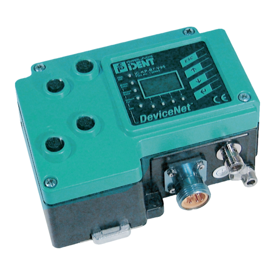
Page 12: Displays And Controls
IC-KP-B7-V95 Product Description Displays and controls The following displays and controls are located on the control interface. IC-KP-B7-V95 PWR/ Part No. 130985 Module Status Network Status Network LED indicators PWR/ERR Power on green Hardware error 1, 2, 3, 4 Status display for R/W heads... -
Page 13: Interfaces And Connections
IC-KP-B7-V95 Product Description Push buttons Down menu item RETURN (confirm input) Interfaces and connections The following interfaces and connections are located on the control interface IC- KP-B7-V95. Connections M12 connector for R/W heads (sockets) - V1 M12 connector for power supply (plug) - V1... -
Page 14: Connection Accessories
IC-KP-B7-V95 Product Description Connection accessories 4.7.1 Connection cable for R/W heads and trigger sensors Compatible connection cables with shielding are available for connecting the R/W heads and trigger sensors. Figure 4.2 Accessories Description 2 m long (straight female, angled male) -
Page 15: Installation
■ Retain the original packaging in case you have to store or ship the device again at a later date. Should you have any questions, please contact Pepperl+Fuchs. EMC concept The outstanding noise immunity of the IDENTControl against emission and immission is based on its consistent shielding design, which uses the principle of the Faraday cage. -
Page 16: Device Connection
IC-KP-B7-V95 Installation Note! If cables with double shields are used, e.g. wire mesh and metalized foil, the both shields must be connected together, with low resistance, at the ends when making up the cable. Power supply cables are the source of much interference, e.g. from the supply lines of 3-phase electric motors. -
Page 17: Read/Write Head And Trigger Sensors
IC-KP-B7-V95 Installation 5.4.2 Read/Write Head and Trigger Sensors A maximum of 4 read/write heads can be connected to the IDENTControl. Instead of the read/write heads, a maximum of 2 trigger sensors can be connected to sockets 3 and 4. A trigger sensor can be assigned to only one read/write head. -
Page 18: Devicenet Connection Guide
IC-KP-B7-V95 Installation 5.4.5 DeviceNet connection guide Network connection The network connection is established using a DeviceNet MiniStyle connector. The pin assignment is taken from the drawing below. Ground / uncoated V+ / RD V- / BK CAN_H / WH CAN_L / BU Connecting cable The device must always be connected using the "Thick"... -
Page 19: Commissioning
IC-KP-B7-V95 Commissioning Commissioning Connection Warning! Before commissioning, check once again that the connections are correct. Before commissioning, familiarize yourself with the system of communication between your DeviceNet control and the read/write station (see chapter 7). Commissioning requires accurate knowledge of DeviceNet communication. - Page 20 IC-KP-B7-V95 Commissioning Non-volatile parameters Parameter Default setting Value range General LCD contrast 36 ... 71 LCD light On / off Language English English / German Multiplex mode On / off R/W head Trigger mode On / off Tag type 00 ... FF...
-
Page 21: Operating The Device
IC-KP-B7-V95 Commissioning 6.3.1 Operating the device The following illustration shows how the device is operated directly: Version IDENT- Config Show Config MultiplexM. information Control... IdentControl IdentControl IPH1 IPH2 IPH3 IPH4 IPH1 IPH2 IPH3 IPH4 IPH1 IPH2 IPH3 IPH4 IPH1 IPH2 IPH3 IPH4... -
Page 22: Output Of The Contents Of Read Data Carriers On The Display
IC-KP-B7-V95 Commissioning Output of the contents of read data carriers on the display In the first menu level, the IDENTControl shows the contents of read data carriers on the display. Information messages of this kind are marked with a bell icon ( in the top right corner of the display to distinguish them from menu items. -
Page 23: Commands
IC-KP-B7-V95 Commands Commands Communication via DeviceNet 7.1.1 General information on communication via DeviceNet DeviceNet is an open fieldbus standard that enables data exchange between programmable logic controllers (PLCs), personal computers (PCs), control and monitoring systems as well as sensors and actuators. Please visit the ODVA website at www.odva.org for more information about DeviceNet. -
Page 24: Separated Mode
IC-KP-B7-V95 Commands 7.1.6 Separated mode Output command object Input command object Class 65h Class 64h Instance 01 Instance 01 Channel 1 Attributes 1-4 Attributes 1-4 Class 65h Class 64h Instance 02 Instance 02 Channel 2 Attributes 1-4 Attributes 1-4 Class 65h... -
Page 25: Assembly Attributes
IC-KP-B7-V95 Commands attribute 4 attribute 3 attribute 2 attribute 1 7.1.8 Assembly attributes The attributes of the output object (class 64h) and the input objects (class 65h) appear in different combinations in the assembly object. 26 assembly instances can be used in pairs for implicit communication and so there are 13 possible combinations. -
Page 26: Access Administration
IC-KP-B7-V95 Commands 7.1.9 Access administration The assembly object is a collection of attributes from classes 64h and 65h (input and output). Both implicit and explicit access to these objects is possible (via the assembly object). Simultaneous access is regulated as follows to prevent the attributes from overwriting one another. -
Page 27: Data Hold Time
IC-KP-B7-V95 Commands The advantage of this procedure is that only a few data bytes are transferred via the bus. Ident commands are transferred as the ident system as explicit commands. A new ident response can be read as soon as the value on the reply counter changes. - Page 28 IC-KP-B7-V95 Commands Command: Byte 0* Telegram length, high byte Byte 1* Telegram length, low byte Byte 2 Command code Byte 3 Channel/toggle bit = 0 Byte 4 Parameters Byte 5 Parameters Byte 6 Data to be written Byte N Data to be written Table 7.1...
-
Page 29: Command Examples
IC-KP-B7-V95 Commands 7.2.1 Command examples Example: Define tag type Command: Change tag type on channel 1 to IPC03 04:02:30:33 (hexadecimal format) Command code CT (change tag) Reserved/Channel (1), toggle bit 0b 30:33 tag type (IPC03) Confirmation 04:02:FF:01 Repeat command code CT (change tag) -
Page 30: Command Types
IC-KP-B7-V95 Commands Confirmation 10:22:FF:01 Repeat command code SR (single read words) Number of double words (2) / channel (1), toggle bit Status FFh (processing command) Reply counter Response: Type IPC03 tag is located in front of the read/write head, the... -
Page 31: Command Overview
IC-KP-B7-V95 Commands Command overview The commands in the list are described in detail on the following pages. System commands Command Abbre code Command description viation See "Change tag (CT):" on page 33 See "Quit (QU):" on page 36 See "Reset (RS):" on page 36 155d See "Set multiplexed mode (MM):"... - Page 32 IC-KP-B7-V95 Commands IPC03 configuration Command Abbre code Command description viation See "Single get configuration (SG):" on page 50 104d See "Enhanced buffered get configuration (EG):" on page 51 See "Single write configuration (SC):" on page 52 102d See "Enhanced buffered write configuration (EC):" on page 53 Extended commands for tag type IPC11 and IDC-...-1K...
-
Page 33: See "Change Tag (Ct)
IC-KP-B7-V95 Commands 7.4.1 System commands Change tag (CT): Byte Contents Bit no. Byte 0 Command code (04h) Byte 1 Reserved/Ident channel/Toggle bit <Channel> <T> Byte 2 Tag type in ASCII <TagType> (high byte) Byte 3 Tag type in ASCII <TagType> (low byte) - Page 34 IC-KP-B7-V95 Commands Tag type Chip type Access Writable Read Frequency desig- memory only range nation [bytes] code High length byte byte [byte] IQC23 my-D SRF55V02P Read/write 13.56 MHz (Infinion) read only code IQC24 my-D SRF55V10P Read/write 13.56 MHz (Infinion) read only...
- Page 35 The tag type configured in the read/write head as the default is selected. Read/write tags can have 4-byte (older versions) or 7-byte UIDs. IQC42 and IQC43 type read/write tags from Pepperl+Fuchs generally have 7-byte UIDs. Note! In a plant where only one tag type is used, it is advantageous to permanently configure that tag type so that the read/write head detects the tag quicker.
-
Page 36: See "Quit (Qu)
IC-KP-B7-V95 Commands Quit (QU): Byte Contents Bit no. Byte 0 Command code (02h) Byte 1 Reserved/Ident channel/Toggle bit <Channel> <T> Response: Byte Contents Bit no. Byte 0 Command code (02h) Byte 1 Reserved/Ident channel/Toggle bit <Channel> <T> Byte 2 Status <Status>... -
Page 37: See "Set Multiplexed Mode (Mm)
IC-KP-B7-V95 Commands Set multiplexed mode (MM): Byte Contents Bit no. Byte 0 Command code (9Bh) Byte 1 Reserved/Toggle bit <T> Byte 2 Multiplex mode <F> Response: Byte Contents Bit no. Byte 0 Command code (9Bh) Byte 1 Reserved/Toggle bit <T>... -
Page 38: See "Set Trigger Mode (Tm)
IC-KP-B7-V95 Commands Set trigger mode (TM): Byte Contents Bit no. Byte 0 Command code (9Ch) Byte 1 Ident channel/sensor channel/toggle bit <Ident channel> <Sensor channel> <T> Byte 2 Trigger mode <Trigger mode> Response: Byte Contents Bit no. Byte 0 Command code (9Ch) -
Page 39: Standard Read/Write Commands
IC-KP-B7-V95 Commands 7.4.2 Standard read/write commands Single read read only code (SF): Byte Contents Bit no. Byte 0 Command code (01h) Byte 1 Reserved/Channel/Toggle bit <Channel> <T> Response: Byte Contents Bit no. Byte 0 Command code (01h) Byte 1 Reserved/Channel/Toggle bit <Channel>... -
Page 40: See "Enhanced Buffered Read Read Only Code (Ef)
IC-KP-B7-V95 Commands Enhanced buffered read read only code (EF): Byte Contents Bit no. Byte 0 Command code (1Dh) Byte 1 Reserved/Ichannel/Toggle bit <Channel> <T> Response: Byte Contents Bit no. Byte 0 Command code (1Dh) Byte 1 Reserved/Ident channel/Toggle bit <Channel>... -
Page 41: See "Single Read Words (Sr)
IC-KP-B7-V95 Commands Single read words (SR): Byte Contents Bit no. Byte 0 Command code (10h) Byte 1 Word number/Channel/Toggle bit <WordNum> <Channel> <T> Byte 2 Word address <WordAddr>(high byte) Byte 3 Word address <WordAddr> (low byte) Response: Byte Contents Bit no. -
Page 42: See "Enhanced Buffered Read Words (Er)
IC-KP-B7-V95 Commands Enhanced buffered read words (ER): Byte Contents Bit no. Byte 0 Command code (19h) Byte 1 Word number/Ident channel/Toggle bit <WordNum> <Channel> <T> Byte 2 Word address <WordAddr>(high byte) Byte 3 Word address <WordAddr> (low byte) Response: Byte Contents Bit no. -
Page 43: See "Single Write Words (Sw)
IC-KP-B7-V95 Commands Single write words (SW): Byte Contents Bit no. Byte 0 Command code (40h) Byte 1 Word number/Ident channel/Toggle bit <WordNum> <Channel> <T> Byte 2 Word address <WordAddr>(high byte) Byte 3 Word address <WordAddr> (low byte) Byte 4 Data 00h ... FFh <Data>... -
Page 44: See "Enhanced Buffered Write Words (Ew)
IC-KP-B7-V95 Commands Enhanced buffered write words (EW): Byte Contents Bit no. Byte 0 Command code (1Ah) Byte 1 Word number/Ident channel/Toggle bit <WordNum> <Channel> <T> Byte 2 Word address <WordAddr>(high byte) Byte 3 Word address <WordAddr> (low byte) Byte 4 Data 00h ... - Page 45 IC-KP-B7-V95 Commands Address Meaning <WordAddr> <ConfAddr> Note Word 0 Password Write only Word 1 Protection word Read/write Word 2 Control word Read/write Word 3 ...31 Data range 00h ... 1Ch Read/write Word 32 Device Serial Number Read only Word 33...
- Page 46 IC-KP-B7-V95 Commands If the password mode in the data carrier is deactivated, every data word on the data carrier can be read or written. The default password of the R/W heads and the data carrier is 00000000h. In the R/W head, the password is stored in the volatile memory and in the data carrier, the password is stored in the non-volatile memory.
- Page 47 IC-KP-B7-V95 Commands Set password mode (PM): Byte Contents Bit no. Byte 0 Command code (18h) Byte 1 Reserved/Ident channel/Toggle bit <Channel> <T> Byte 2 Password mode <P> Response: Byte Contents Bit no. Byte 0 Command code (18h) Byte 1 Reserved/Ident channel/Toggle bit <Channel>...
- Page 48 IC-KP-B7-V95 Commands Change password (PC): Byte Contents Bit no. Byte 0 Command code (41h) Byte 1 Reserved/Ident channel/Toggle bit <Channel> <T> Byte 2 Old password 00h ... FFh <PSW> (byte 3) Byte 3 Old password 00h ... FFh <PSW> (byte 2) Byte 4 Old password 00h ...
- Page 49 IC-KP-B7-V95 Commands Set password (PS): Byte Contents Bit no. Byte 0 Command code (42h) Byte 1 Reserved/Ident channel/Toggle bit <Channel> <T> Byte 2 Reserved Byte 3 Reserved Byte 4 Password 00h ... FFh <PSW> (byte 3) Byte 5 Password 00h ... FFh <PSW>...
- Page 50 IC-KP-B7-V95 Commands Setting "Default Read" 1. Activate the password mode. 2. Write the read range start and end into the "Control Word". 3. Deactivate the password mode. 4. Read the data range with address designation 0000h and word count 0h.
- Page 51 IC-KP-B7-V95 Commands Enhanced buffered get configuration (EG): Byte Contents Bit no. Byte 0 Command code (68h) Byte 1 Reserved/Ident channel/Toggle bit <Channel> <T> Byte 2 Reserved Byte 3 Address in the configuration range <ConfAddr> Response: Byte Contents Bit no. Byte 0...
- Page 52 IC-KP-B7-V95 Commands Single write configuration (SC): Byte Contents Bit no. Byte 0 Command code (12h) Byte 1 Reserved/Ident channel/Toggle bit <Channel> <T> Byte 2 Reserved Byte 3 Address in the configuration range <ConfAddr> Byte 4 Data 00h ... FFh <Data byte 3>...
- Page 53 IC-KP-B7-V95 Commands Enhanced buffered write configuration (EC): Byte Contents Bit no. Byte 0 Command code (66h) Byte 1 Reserved/Ident channel/Toggle bit <Channel> <T> Byte 2 Reserved Byte 3 Address in the configuration range <ConfAddr> Byte 4 Data 00h ... FFh <Data byte 3>...
- Page 54 IC-KP-B7-V95 Commands Tags IDC-...- 1K can be programmed to behave like the ICC read only tag. This programming occupies the first 8 bytes in the tag and occurs when the tag type '50' is set with the commands SX or EX.
- Page 55 IC-KP-B7-V95 Commands Enhanced buffered write read only code (EX): Byte Contents Bit no. Byte 0 Command code (24h) Byte 1 FixLen/Channel/Toggle bit <FixLen> <Channel> <T> Byte 2 FixType <FixType> (high byte) Byte 3 FixType <FixType> (low byte) Byte 4 Data 00h ... FFh <Data>...
- Page 56 IC-KP-B7-V95 Commands Set tag ID code (TI) Command: Byte Content Bit no. Byte 0 Command code (BCh) Byte 1 ID length/Channel/Toggle bit <ByteNum> <Channel> <T> Byte 2 Data <ID code> Byte 3 Data <ID code> Byte 4 Data <ID code>...
- Page 57 IC-KP-B7-V95 Commands Fill data carrier (S#) Command: Byte Content Bit no. Byte 0 Command code (AAh) Byte 1 Reserved/Ident channel/Toggle bit <Reserved> <Channel> <T> Byte 2 Start address <WordAddr> (high byte) Byte 3 Start address <WordAddr> (low byte) Byte 4 Word count <WordNum>...
- Page 58 IC-KP-B7-V95 Commands Single read special fixcode (SS) Command: Byte Content Bit no. Byte 0 Command code (0Ah) Byte 1 FixLen/Ident channel/Toggle bit <FixLen> <Channel> <T> Byte 2 not used Byte 3 not used Byte 4 not used Byte 5 not used...
- Page 59 IC-KP-B7-V95 Commands Enhanced read special fixcode (ES) Command: Byte Content Bit no. Byte 0 Command code (71h) Byte 1 Word number/Ident channel/Toggle bit <FixLen> <Channel> <T> Byte 2 not used Byte 3 not used Byte 4 not used Byte 5...
- Page 60 IC-KP-B7-V95 Commands Single program special fixcode (SP) Command: Byte Content Bit no. Byte 0 Command code (0Dh) Byte 1 Word number/Ident channel/Toggle bit <FixLen> <Channel> <T> Byte 2 Reserved Byte 3 Reserved Byte 4 ID code 00h ... FFh <ID code>...
- Page 61 IC-KP-B7-V95 Commands Enhanced program special fixcode (EP) Command: Byte Content Bit no. Byte 0 Command code (75h) Byte 1 FixLen/Ident channel/Toggle bit <FixLen> <Channel> <T> Byte 2 Reserved Byte 3 Reserved Byte 4 ID code 00h ... FFh <ID code>...
- Page 62 IC-KP-B7-V95 Commands Note! The <FixLen> of IDC-...-1K read/write tags is always 6 bytes. Initialize data carrier (SI): Byte Contents Bit no. Byte 0 Command code (6Bh) Byte 1 Reserved/Channel/Toggle bit <Channel> <T> Response: Byte Contents Bit no. Byte 0 Command code (6Bh)
- Page 63 IC-KP-B7-V95 Commands Extended commands for IQH2-... read/write heads read param (RP) Command: Byte Contents Bit no. Telegram length, high byte Byte 0 Telegram length, low byte Byte 1 Byte 2 Command code (BEh) Byte 3 Reserved/Ident channel/Toggle bit <Channel> <T>...
-
Page 64: Byte 3 Reserved/Ident Channel/Toggle Bit
IC-KP-B7-V95 Commands write param (WP) Command: Byte Contents Bit no. Telegram length, high byte Byte 0 Telegram length, low byte Byte 1 Byte 2 Command code (BFh) Byte 3 Reserved/Ident channel/Toggle bit <Channel> <T> Byte 4 System code <SystemCode> (high byte) -
Page 65: Byte
IC-KP-B7-V95 Commands IQH2-...: <SystemCode> 'Q' ASCII (51 <ParamTyp> 'K1' ASCII (4B RP: reads the key (12 characters ASCII from 0 ... F) from the transponder and the read head WP: writes the key (12 characters ASCII from 0 ... F) -
Page 66: Fault/Status Messages
IC-KP-B7-V95 Commands <Month> : 2 bytes ASCII, hexadecimal encoding, 01 ... 0C (01=January, 0C=December) <P> : 1 bit, password mode, 0 (0b): Mode off, 1 (1b): Mode on <PW> : 4 bytes HEX, password <ReplyCounter> : 1 byte, increases by 1 after each response and confirmation. The reply counter starts from 0 after the system is switched on. - Page 67 IC-KP-B7-V95 Commands Status Meaning Reserved Reserved Reserved Error messages sent by the bus connection Status Meaning Reserved Reserved Incorrect or incomplete command or parameter not in the valid range. Hardware error, e.g. no communication with the identification system. Internal device error.
-
Page 68: Technical Specifications
IC-KP-B7-V95 Technical specifications Technical specifications Dimensions Ground Connector array General data General data Number of R/W heads max. 4 alternatively 2 R/W heads and 2 trigger sensors Displays/controls LEDs 1, 2, 3, 4 Status display for R/W heads green: Command to R/W head active yellow: Approx. - Page 69 IC-KP-B7-V95 Technical specifications LED network PWR green: Network voltage available green flashing: LED test LED COM Yellow: Data exchange yellow flashing: LED test LC display Two-line multifunction display with 12 characters per line Configuration of the control interface and display of...
-
Page 70: Troubleshooting
IC-KP-B7-V95 Troubleshooting Troubleshooting Fault location Fault source Possible cause Remedy The operating voltage LED Power supply is interrupted. Ensure that the power (PWR/ERR) does not light supply is connected to a 24 V DC source. The LED on the M12 plug... -
Page 71: Ascii Table
IC-KP-B7-V95 ASCII table ASCII table ASCII ASCII ASCII ASCII Space " & < >... -
Page 72: Appendix A
IC-KP-B7-V95 Appendix A Appendix A 11.1 Example 1 The following example uses assembly objects 101d/151d (mixed mode) and results in the following: Setting the data carrier IPC02 on channel 1 and channel 3. ■ Reading the read only code from an IPC02 data carrier. - Page 73 IC-KP-B7-V95 Appendix A Byte no. Contents Description Byte 2 Status Processing command. Byte 3 Reply counter For every IDENT telegram, the value on the reply counter increases by 1. Byte 4 Byte 11 A response appears in the input field: Byte no.
- Page 74 IC-KP-B7-V95 Appendix A A response appears in the input field: Byte no. Contents Description Byte 0 Command code Command CT (Change tag) Byte 1 Number of double words/ Channel = 3 Channel/Toggle bit Toggle bit = 0 Byte 2 Status Command executed.
- Page 75 IC-KP-B7-V95 Appendix A A command confirmation appears in the input field: Byte no. Contents Description Byte 0 Command code Command SF (Single read read only code) Byte 1 Channel/Toggle bit Channel = 1 Toggle bit = 0 Byte 2 Status Processing command.
- Page 76 IC-KP-B7-V95 Appendix A Send a Single readcommand to channel 3 as an implicit command: Byte no. Contents Description Byte 0 Command code Command SF (Single read read only code) Byte 1 Channel/Toggle bit Channel = 3 Toggle bit = 0...
-
Page 77: Example 2
IC-KP-B7-V95 Appendix A A response appears in the input field: Byte no. Contents Description Byte 0 Command code Command SF (Single read read only code) Byte 1 Channel/Toggle bit Channel = 3 Toggle bit = 0 Byte 2 Status Command executed. - Page 78 IC-KP-B7-V95 Appendix A The selected input and output instances of the assembly object is divided as follows: Output instance 104d - 32 bytes Bytes Class, instance, attribute Description 0 - 7 64h, 01d, 01h Channel 1 [8] 8 - 15...
-
Page 79: Byte
IC-KP-B7-V95 Appendix A Ele- Implicit Con- Description ment telegram tents Byte 8 Command code Command CT (Change tag) Byte 9 Channel/Toggle bit The element defined the channel. Toggle bit = 0 Byte 10 Tag type (high byte) IPC 03 Byte 11... - Page 80 IC-KP-B7-V95 Appendix A Ele- Implicit Con- Description ment telegram tents Byte 8 Command code (Echo) Command CT (Change tag) Byte 9 Channel/Toggle bit Channel = element = 2 Toggle bit = 0 Byte 10 Status Processing command. Byte 11 Reply counter...
-
Page 81: Data 00
IC-KP-B7-V95 Appendix A Ele- Implicit Con- Description ment telegram tents Byte 8 Command code Command CT (Change tag) Byte 9 Number of double words/ Channel = element = 2 Channel/Toggle bit Toggle bit = 0 Byte 10 Status Processing command. - Page 82 IC-KP-B7-V95 Appendix A Ele- Implicit Con- Description ment telegram tents Byte 8 Command code Command SW (Single write double words) Byte 9 Number of double words/ 1 double word = 4 bytes Channel/Toggle bit Element defines the channel. Toggle bit = 0...
-
Page 83: Byte
IC-KP-B7-V95 Appendix A Ele- Implicit Con- Description ment telegram tents Byte 8 Command code Command SW (Single write double words) Byte 9 Number of double words/ 1 double word = 4 bytes Channel/Toggle bit Channel = element = 1 Toggle bit = 0... - Page 84 IC-KP-B7-V95 Appendix A Ele- Implicit Con- Description ment telegram tents Byte 8 Command code Command SW (Single write double words) Byte 9 Number of double words/ Element defines channel. Channel/Toggle bit Toggle bit = 0 Byte 10 Status Command executed.
- Page 85 IC-KP-B7-V95 Appendix A Ele- Implicit Con- Description ment telegram tents Byte 8 Command code Command SR (Single read double words) Byte 9 Number of double words/ 1 double word = 4 bytes Channel/Toggle bit Element defines the channel. Toggle bit = 0...
- Page 86 IC-KP-B7-V95 Appendix A Ele- Implicit Con- Description ment telegram tents Byte 8 Command code Command SR (Single read words) Byte 9 Number of double words/ 1 double word = 4 bytes Channel/Toggle bit Channel = element = 1 Toggle bit = 0...
- Page 87 IC-KP-B7-V95 Appendix A Ele- Implicit Con- Description ment telegram tents Byte 8 Command code Command SR (Single read words) Byte 9 Number of double words/ 1 double word = 4 bytes Channel/Toggle bit Channel = element = 2 Toggle bit = 0...
-
Page 88: Appendix B
IC-KP-B7-V95 Appendix B Appendix B 12.1 Object model Class Object name Number of instances Identity Assembly Output command for channels 1-4, IDENTControl and mixed mode Input command for channels 1-4, IDENTControl and mixed mode Boot-up parameters Diagnostics 12.1.1 Identity object (01h) -
Page 89: Assembly Object (04H)
IC-KP-B7-V95 Appendix B 12.1.2 Assembly object (04h) These instances are taken from classes 64h and 65h. Class attributes (instance 0) Attribute ID Name Data type Data content Access authoriza- tion Revision UINT Max. instance UINT I/O output instance USINT Get / Set... - Page 90 IC-KP-B7-V95 Appendix B Output instance 104d - 32 bytes Bytes Class, instance, attribute Description 0 - 7 64h, 01d, 01h Channel 1 [8] 8 - 15 64h, 02d, 01h Channel 2 [8] 16 - 23 64h, 03d, 01h Channel 3 [8]...
- Page 91 IC-KP-B7-V95 Appendix B Output instance 109d - 56 bytes Bytes Class, instance, attribute Description 0 - 11 64h, 01d, 02h Channel 1 [12] 12 - 23 64h, 02d, 02h Channel 2 [12] 24 - 35 64h, 03d, 02h Channel 3 [12]...
- Page 92 IC-KP-B7-V95 Appendix B Input instance attributes (instances 150d-162d) Attribute ID Name Data type Data content Access authoriza- tion Input data USINT [8-248] Input instance 150d - 8 bytes Bytes Class, instance, attribute Description 0 - 7 65h, 06d, 01h Mixed mode [8]...
- Page 93 IC-KP-B7-V95 Appendix B Input instance 156d - 128 bytes Bytes Class, instance, attribute Description 0 - 31 65h, 01d, 03h Channel 1 [32] 32 - 63 65h, 02d, 03h Channel 2 [32] 64 - 95 65h, 03d, 03h Channel 3 [32]...
- Page 94 IC-KP-B7-V95 Appendix B Input instance 161d - 248 bytes Bytes Class, instance, attribute Description 0 - 59 65h, 01d, 04h Channel 1 [60] 60 - 119 65h, 02d, 04h Channel 2 [60] 120 - 179 65h, 03d, 04h Channel 3 [60]...
- Page 95 IC-KP-B7-V95 Appendix B Shared services Service code integrated in service designation Class level Instance level Get attribute single Set attribute single 12.1.4 Input command object (instances 65h - 6) Class attributes (instance 0) Attribute ID Name Data type Data content...
- Page 96 IC-KP-B7-V95 Appendix B 12.1.5 Boot-up parameter object (instances 66h - 4) Class attributes (instance 0) Attribute ID Name Data type Data content Access authoriza- tion Revision UINT Multiplex mode BOOL Get / Set Data retention time USINT Get / Set...
- Page 97 IC-KP-B7-V95 Appendix B Instance attributes (instance 5, IDENTControl) Attribute ID Name Data type Data content Access authoriza- tion Unused Version Bytes [52] Shared services Service code integrated in service designation Class level Instance level Get attribute single Set attribute single...
- Page 98 Twinsburg, Ohio 44087 · USA Tel. +1 330 4253555 E-mail: sales@us.pepperl-fuchs.com Asia Pacific Headquarters Pepperl+Fuchs Pte Ltd. Company Registration No. 199003130E Singapore 139942 Tel. +65 67799091 E-mail: sales@sg.pepperl-fuchs.com www.pepperl-fuchs.com Subject to modifications Copyright PEPPERL+FUCHS • Printed in Germany TDOCT0845D_ENG 04/2013...
Need help?
Do you have a question about the IC-KP-B7-V95 and is the answer not in the manual?
Questions and answers