
Related Manuals for Pepperl+Fuchs IC-KP-B6-V15B


Summary of Contents for Pepperl+Fuchs IC-KP-B6-V15B
- Page 1 FACTORY AUTOMATION MANUAL IC-KP-B6-V15B IDENTControl interface with PROFIBUS DP interface...
- Page 2 IC-KP-B6-V15B With regard to the supply of products, the current issue of the following document is applicable: The General Terms of Delivery for Products and Services of the Electrical Industry, published by the Central Association of the Electrical Industry (Zentralverband Elektrotechnik und Elektroindustrie (ZVEI) e.V.) in its most recent version as well as the supplementary clause: "Expanded reservation...
-
Page 3: Table Of Contents
IC-KP-B6-V15B Contents 1 Introduction................. 5 2 Declaration of conformity ..........6 Declaration of conformity ................6 3 Safety ................... 7 Symbols relevant to safety ................7 Intended use ....................7 General notes on safety.................7 Contact protection..................8 4 Product Description ............9 Range of application ..................9 Device characteristics ...................9... - Page 4 IC-KP-B6-V15B Contents 6 Commissioning ..............23 Connection....................23 Preliminary considerations ................. 23 Device settings................... 24 6.3.1 Operating the device................25 Output of the contents of read data carriers on the display ......25 6.4.1 Setting the device address ..............26 6.4.2 Setting the bus protocol .................
-
Page 5: Introduction
Introduction Introduction Congratulations You have chosen a device manufactured by Pepperl+Fuchs. Pepperl+Fuchs develops, produces and distributes electronic sensors and interface modules for the market of automation technology on a worldwide scale. Before installing this equipment and put into operation, read this manual carefully. -
Page 6: Declaration Of Conformity
This product was developed and manufactured under observance of the applicable European standards and guidelines. Note! A Declaration of Conformity can be requested from the manufacturer. The product manufacturer, Pepperl+Fuchs GmbH, D-68307 Mannheim, has a certified quality assurance system that conforms to ISO 9001. ISO9001... -
Page 7: Safety
In case of ignoring the devices and any connected facilities or systems may be interrupted or fail completely. Intended use The IDENTControl IC-KP-B6-V15B is a control interface including a PROFIBUS interface for identification systems. The device can be used as a control cabinet module or for field applications. Besides the PROFIBUS connection, suitable inductive R/W heads, microwave antennas or trigger sensors can be connected. -
Page 8: Contact Protection
IC-KP-B6-V15B Safety Note! Disposal Electronic waste is hazardous waste. When disposing of the equipment, observe the current statutory requirements in the respective country of use, as well as local regulations. Contact protection Our housings are manufactured using components made partly or completely from metal to improve noise immunity. -
Page 9: Product Description
IC-KP-B6-V15B Product Description Product Description Range of application The system is suited for the following applications: Automation ■ Material flow control in production ■ Acquisition of operating data ■ Access control ■ Identification of storage vessels, pallets, work piece carriers, refuse ■... -
Page 10: Code / Data Carrier
Read/write tags in this frequency range save larger quantities of data and offer a considerably higher reading speed than read/write tags of the 125 kHz system. IQH-* and IQH1-* read/write heads from Pepperl+Fuchs are compatible with most existing read/write tags that comply with standard ISO 15693. With the IQH2-* read/write heads you can use read/write tags that comply with standard ISO 14443A. -
Page 11: Displays And Controls
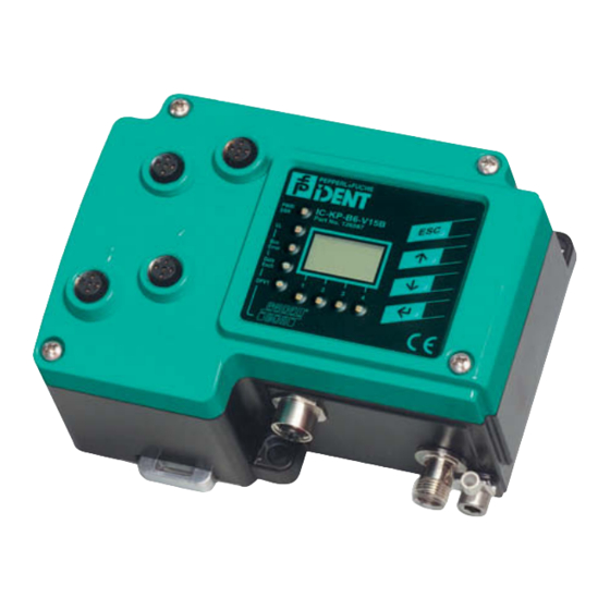
IC-KP-B6-V15B Product Description Displays and controls The following displays and controls are located on the control interface. IC-KP-B6-V15B PWR/ Part No. 126087 Error Data Exch DPV1 P R O F I B U S LED indicators PWR/ERR Power on green... -
Page 12: Interfaces And Connections
IC-KP-B6-V15B Product Description Interfaces and connections The following interfaces and connections are located on the IC-KP-B6-V15B control interface. Connections M12 connector for R/W heads (sockets) - V1 M12 connector for power supply (plug) - V1 M12 connector for PROFIBUS connection - V15B... -
Page 13: Connection Accessories
IC-KP-B6-V15B Product Description Connection accessories 4.7.1 Connection cable for R/W heads and trigger sensors Compatible connection cables with shielding are available for connecting the R/W heads and trigger sensors. Figure 4.2 Accessories Description 2 m long (straight female, angled male) -
Page 14: Cable Connectors For The Power Supply
IC-KP-B6-V15B Product Description 4.7.2 Cable connectors for the power supply Compatible M12 sockets with an open cable end for connecting the IDENTControl to a power supply are available in different lengths. Figure 4.3 Accessories Designation Length 2 m (straight socket) - Page 15 IC-KP-B6-V15B Product Description Note! The T-distributor is designed for general applications in the PROFIBUS network only and is not compatible with the IDENT Control. The Y connection cable must always be used with the IDENT Control.
-
Page 16: Installation
■ Retain the original packaging in case you have to store or ship the device again at a later date. Should you have any questions, please contact Pepperl+Fuchs. EMC concept The outstanding noise immunity of the IDENTControl against emission and immission is based on its consistent shielding design, which uses the principle of the Faraday cage. -
Page 17: Device Connection
IC-KP-B6-V15B Installation Note! If cables with double shields are used, e.g. wire mesh and metalized foil, the both shields must be connected together, with low resistance, at the ends when making up the cable. Power supply cables are the source of much interference, e.g. from the supply lines of 3-phase electric motors. -
Page 18: Cable Length Between Control Interface And R/W Heads
IC-KP-B6-V15B Installation trigger switch signal For details of compatible read/write heads see chapter 4.3.1. and of compatible connecting cables, see chapter 4.7.1. 5.4.3 Cable length between control interface and R/W heads The maximum cable length between the control interface and a connected R/W head is 1000 meters. -
Page 19: Cables
IC-KP-B6-V15B Installation The PROFIBUS DP is connected via a B-encoded M12 socket. This socket is connected to the Y line ICZ-3T-0.2M-PUR ABG-V15B-G so that it can be connected to the bus. Other Y lines can also be connected. Several IDENTControls can be connected directly to the PROFIBUS via several Y lines. -
Page 20: Transfer Rates And Line Lengths
With the PROFIBUS DP, every bus segment must be terminated on both line ends with terminating resistors. An external terminator must be attached for the last node. Pluggable terminators (ICZ-TR-V15B, for example) are available from Pepperl+Fuchs and is easy to connect using a ICZ-3T-V15B T-piece. Note! We recommend using a Y-splitter cordset because the fixed connection to the T- piece allows greater leverage on the connector insert. - Page 21 IC-KP-B6-V15B Installation Connection layout and dimensions of the Y-piece and Y-splitter cordset Dimensions of the ICZ-2T/TR-0.2M-PUR ABG-V15B-G ~ 280 Example: connection of adjacent devices IC-KP-B6-V15B Y connection cable ICZ-3T-0.2M-PUR ABG-V15B-G V15B-G-*M-PUR ABG-V15B-G For last node: ICZ-2T/TR-0.2M-PUR ABG-V15B-G with integrated terminator...
- Page 22 IC-KP-B6-V15B Installation Note! More information on the installation of the PROFIBUS can be found in the brochure: ”PROFIBUS Technical Guidelines, Construction Guidelines PROFIBUS DP/FMS”! The brochure can be obtained from: PROFIBUS Nutzerorganisation e.V. Haid- und Neu-Str. 7 D-76131 Karlsruhe Tel: +49 721 96 58 590 Fax: +49 721 96 58 589 E-mail: PROFIBUS-International@compuserve.com...
-
Page 23: Commissioning
IC-KP-B6-V15B Commissioning Commissioning Connection Warning! Incorrect electrical connection Incorrect connections may damage the system. Before commissioning, familiarize yourself with the system of communication between your PROFIBUS DP and the read/write station. Check all connections before commissioning. After the supply voltage is connected, the green LED in the voltage connector and the PWR and UL LEDs on the display panel must light up. -
Page 24: Device Settings
IC-KP-B6-V15B Commissioning Note! There are configuration tools available to help PROFIBUS DP users plan a network and put it in operation even if they do not have extensive experience with the underlying communication sequences. The system software of PLCs with the PROFIBUS DP communication interface often offers suitable options for configuring and managing a bus. -
Page 25: Operating The Device
IC-KP-B6-V15B Commissioning 6.3.1 Operating the device The following illustration shows how the device is operated directly: Version IDENT- Config Show Config MultiplexM. information Control... IdentControl IdentControl IPH1 IPH2 IPH3 IPH4 IPH1 IPH2 IPH3 IPH4 IPH1 IPH2 IPH3 IPH4 IPH1 IPH2 IPH3 IPH4... -
Page 26: Setting The Device Address
IC-KP-B6-V15B Commissioning The view on the display can be toggled by pressing the arrow buttons. The following display variants are available: HEX (hexadecimal with decimal delimiter) ■ HEX2 (hexadecimal without decimal delimiter) ■ ASCII (ASC) ■ Note! Data carrier content from commands that are activated manually on the IDENTControl are always displayed, irrespective of the menu level that was just displayed. -
Page 27: Setting The Bus Protocol
IC-KP-B6-V15B Commissioning 6.4.2 Setting the bus protocol Setting the bus protocol Set the bus protocol as follows: 1. Select IDENT gateway ... (PROFIBUS settings). 2. Select Set bus protocol using the arrow buttons. 3. Select the relevant mode using the arrow buttons. -
Page 28: Commands
IC-KP-B6-V15B Commands Commands General information on PROFIBUS DP The PROFIBUS DP is a standardized, open fieldbus, which enables data exchange between PLCs, PCs, operating and observation devices, and also sensors and actuators. For more detailed information on the PROFIBUS DP, refer to the PROFIBUS standard EN 50170 and to the current literature on the subject (e.g. -
Page 29: Profibus Dp Functions
IC-KP-B6-V15B Commands 7.1.3 PROFIBUS DP functions Function Description Master Set_Prm Transfers parameter data to a DP slave Class 1 Chk_Cfg Transfers the configuration data for testing to a DP slave Class 1 Get_Cfg Reads out the configuration data of a DP slave... - Page 30 IC-KP-B6-V15B Commands For read only operation: "8 In/4 Out bytes" Corresponds to 1 word Input data (32 bits) "12 In/4 Out bytes" " 2 words " "16 In/4 Out bytes" " 3 words " "20 In/4 Out bytes" " 4 words "...
-
Page 31: Device Identification/Software Version Message For Profibus Dp
IC-KP-B6-V15B Commands 7.3.2 Device identification/software version message for PROFIBUS DP The device identification and the software version are transferred via the DP function “Device-Related Diagnostics”. Address Length Contents Byte 0 1 byte Header byte, length of external diagnostics Byte 1 2 bytes 16 bits external diagnostics (see table "GSD file (device-... - Page 32 IC-KP-B6-V15B Commands Identification byte in ExtDiag: IDENTControl: First character of the connector description IC-KP-B6-V15B => IC-KP-B6-SUBD => Reading head: Second character of the housing design IPH-18GM-V1 => IPH-30GM-V1 => IPH-F15-V1 => IPH-FP-V1 => IPH-F61-V1 => IPH-L2-V1 => Software number of the R/W head: =>...
-
Page 33: Software Information
IC-KP-B6-V15B Commands Example: One type IPH-L2 R/W head is connected to channel 2. Address Length Contents Byte 0 1 byte Byte 1 2 bytes 00h 00h Byte 3 1 byte Byte 4 3 bytes Byte 7 6 bytes 200804 Byte 13... - Page 34 IC-KP-B6-V15B Commands Output data field (command): Byte 0 Command code Byte 1 Parameter/Toggle flag Byte 2 Parameter Byte 3 Parameter Byte 4 Write data Byte N (N is defined by module selection) Write data Input data field (response): Byte 0...
-
Page 35: Command Types
IC-KP-B6-V15B Commands commands, the word count in the response is always 0000b. 3 responses are issued for commands to all connected R/W heads (channel = 111b): The first response (status = FFh) is followed up by 2 other responses that contain the status of the individual channels. - Page 36 IC-KP-B6-V15B Commands Command Command description Abbre code viation 155d See "Set multiplexed mode (MM):" on page 44 156d See "Set trigger mode (TM):" on page 45 Standard read/write commands Fixcode Command Command description Abbre code viation See "single read fixcode (SF)" on page 47 See "Enhanced buffered fixcode (EF)"...
- Page 37 IC-KP-B6-V15B Commands Extended Commands for Type IPC11 and IDC-...-1K Read/Write Tags Command Command description Abbre code viation See "Single write fixcode (SX)" on page 64 See "Enhanced buffered write fixcode (EX)" on page 66 188d See "Set tag ID code (TI)" on page 67 170d See "Fill data carrier (S#)"...
-
Page 38: System Commands
IC-KP-B6-V15B Commands 7.3.6 System commands Change tag (CT) Command: Byte Content Bit no. Byte 0 Command code (04h) Byte 1 <Channel> <T> Reserved/Ident channel/Toggle bit Byte 2 Data carrier type in ASCII <TagType> (high byte) Byte 3 Data carrier type in ASCII <TagType>... - Page 39 IC-KP-B6-V15B Commands Tag type Chip type Access Writable Read only Frequency desig- memory code range High nation [bytes] length byte byte [byte] IPC12 P+F FRAM Read/write read 125 kHz only code All ISO 15693 compliant Read/write read 13.56 MHz IQC20...
- Page 40 The tag type configured in the read/write head as the default is selected. Read/write tags can have 4-byte (older versions) or 7-byte UIDs. IQC42 and IQC43 type read/write tags from Pepperl+Fuchs generally have 7-byte UIDs. Note! In a plant where only one tag type is used, it is advantageous to permanently configure that tag type so that the read/write head detects the tag quicker.
- Page 41 IC-KP-B6-V15B Commands Quit (QU) Command: Byte Content Bit no. Byte 0 Command code (02h) Byte 1 <Channel> <T> Reserved/Ident channel/Toggle bit Byte 2 not used Byte 3 not used Byte 4 not used Byte 5 not used Byte 6 not used...
- Page 42 IC-KP-B6-V15B Commands Configuration store (CS) Command: Byte Contents Bit no. Byte 2 Command code (17h) Byte 3 <Channel> <T> Reserved/Ident channel/Toggle bit Byte 4 Mode <Mode> Byte 5 not used Byte 6 not used Byte 7 not used Byte 8...
- Page 43 IC-KP-B6-V15B Commands Reset (RS) Command: Byte Content Bit no. Byte 0 Command code (16h) Byte 1 Reserved/Channel/Toggle bit <T> Byte 2 not used Byte 3 not used Byte 4 not used Byte 5 not used Byte 6 not used Byte 7 not used This command terminates all active commands.
-
Page 44: 9Bh See "Set Multiplexed Mode (Mm)
IC-KP-B6-V15B Commands Set multiplexed mode (MM): Byte Content Bit no. Byte 0 Command code (9Bh) Byte 1 Reserved/Toggle bit <T> Byte 2 Multiplex mode <F> Byte 3 unused Byte 4 unused Byte 5 unused Byte 6 unused Byte 7 unused... -
Page 45: 9Ch See "Set Trigger Mode (Tm)
IC-KP-B6-V15B Commands Set trigger mode (TM): Byte Contents Bit no. Byte 0 Command code (9Ch) Byte 1 <Ident channel> <Sensor channel> <T> Ident channel/sensor channel/toggle bit Byte 2 Trigger mode <Trigger mode> Byte 3 not used Byte 4 not used... - Page 46 IC-KP-B6-V15B Commands If a read/write command is sent to the triggered channel <Ident channel> when trigger mode is active, this command is always activated if the <Sensor channel> transmits status 0. <Ident channel> transmits status 0 to confirm receipt of this command.
-
Page 47: Standard Read/Write Commands
IC-KP-B6-V15B Commands 7.3.7 Standard read/write commands single read fixcode (SF) Command: Byte Content Bit no. Byte 0 Command code (01h) Byte 1 <Channel> <T> Reserved/Ident channel/Toggle bit Response: Byte Content Bit no. Byte 0 Command code (01h) Byte 1 Reserved/Channel/Toggle bit <Channel>... -
Page 48: 1Dh See "Enhanced Buffered Fixcode (Ef)
IC-KP-B6-V15B Commands Enhanced buffered fixcode (EF) Command: Byte Content Bit no. Byte 0 Command code (1Dh) Byte 1 <Channel> <T> Reserved/Ident channel/Toggle bit Byte 2 not used Byte 3 not used Byte 4 not used Byte 5 not used Byte 6... -
Page 49: See "Single Read Words (Sr)
IC-KP-B6-V15B Commands single read words (SR) Command: Byte Content Bit no. Byte 0 Command code (10h) Byte 1 <WordNum> <Channel> <T> Word number/Ident channel/Toggle bit Byte 2 Word address <WordAddr> (high byte) Byte 3 Word address <WordAddr> (low byte) Byte 4... -
Page 50: See "Enhanced Buffered Read Words (Er)
IC-KP-B6-V15B Commands enhanced buffered read words (ER) Command: Byte Content Bit no. Byte 0 Command code (19h) Byte 1 <WordNum> <Channel> <T> Word number/Ident channel/Toggle bit Byte 2 Word address <WordAddr> (high byte) Byte 3 Word address <WordAddr> (low byte) -
Page 51: See "Single Write Words (Sw)
IC-KP-B6-V15B Commands single write words (SW) Command: Byte Content Bit no. Byte 0 Command code (40h) Byte 1 <WordNum> <Channel> <T> Word number/Ident channel/Toggle bit Byte 2 Word address <WordAddr> (high byte) Byte 3 Word address <WordAddr> (low byte) Byte 4 Data 00h ... -
Page 52: 1Ah See "Enhanced Buffered Write Words (Ew)
IC-KP-B6-V15B Commands enhanced buffered write words (EW) Command: Byte Content Bit no. Byte 0 Command code (1Ah) Byte 1 <WordNum> <Channel> <T> Word number/Ident channel/Toggle bit Byte 2 Word address <WordAddr> (high byte) Byte 3 Word address <WordAddr> (low byte) Byte 4 Data 00h ... -
Page 53: Ipc03 Configuration
IC-KP-B6-V15B Commands 7.3.8 Special commands Commands for the data carrier IPC03 Note! You can only use the commands in this section for the data carrier type '03' (IPC03). IPC03 Configuration The storage of a data carrier IPC03 is organized by word. A data word is defined with a length of 32 bits. -
Page 54: Changing The Password
IC-KP-B6-V15B Commands Control word Meaning Byte 0 ... 7 Read range start 8 ... 15 Read range end Password mode on/off "Read after write" operating mode on/off 18 ... 23 Open 24 ... 31 Open IPC03 password mode If the password mode in the data carrier is activated, the data range of the data carrier is read and write-protected and can only be read or written if the R/W head sends the correct password to the data carrier. -
Page 55: See "Set Password Mode (Pm)
IC-KP-B6-V15B Commands Set password mode (PM) Command: Byte Content Bit no. Byte 0 Command code (18h) Byte 1 <Channel> <T> Reserved/Ident channel/Toggle bit Byte 2 Password mode <P> Byte 3 not used Byte 4 not used Byte 5 not used... -
Page 56: See "Change Password (Pc)
IC-KP-B6-V15B Commands Change password (PC) Command: Byte Content Bit no. Byte 0 Command code (41h) Byte 1 <Channel> <T> Reserved/Ident channel/Toggle bit Byte 2 Old password 00h ... FFh <PSW> (byte 3) Byte 3 Old password 00h ... FFh <PSW> (byte 2) Byte 4 Old password 00h ... -
Page 57: See "Set Password (Ps)
IC-KP-B6-V15B Commands Set password (PS) Command: Byte Content Bit no. Byte 0 Command code (42h) Byte 1 <Channel> <T> Reserved/Ident channel/Toggle bit Byte 2 Reserved Byte 3 Reserved Byte 4 Password 00h ... FFh <PSW> (byte 3) Byte 5 Password 00h ... FFh <PSW>... - Page 58 IC-KP-B6-V15B Commands The advantage of "default read" operating mode is the readout speed. The readout of one data word (4 bytes) is twice as fast in this mode as the other modes. The readout of two words takes approx. 1/3 less time. No more time advantages can be gained after three data words because "default read"...
-
Page 59: See "Single Get Configuration (Sg)
IC-KP-B6-V15B Commands IPC03 configuration Single get configuration (SG) Command: Byte Content Bit no. Byte 0 Command code (61h) Byte 1 <Channel> <T> Reserved/Ident channel/Toggle bit Byte 2 Reserved Byte 3 <ConfAddr> Address in the configuration range Byte 4 not used... -
Page 60: See "Enhanced Buffered Get Configuration (Eg)
IC-KP-B6-V15B Commands Enhanced buffered get configuration (EG) Command: Byte Content Bit no. Byte 0 Command code (68h) Byte 1 <Channel> <T> Reserved/Ident channel/Toggle bit Byte 2 Reserved Byte 3 <ConfAddr> Address in the configuration range Byte 4 not used Byte 5... -
Page 61: See "Single Write Configuration (Sc)
IC-KP-B6-V15B Commands Single write configuration (SC) Command: Byte Content Bit no. Byte 0 Command code (12h) Byte 1 <Channel> <T> Reserved/Ident channel/Toggle bit Byte 2 Reserved Byte 3 <ConfAddr> Address in the configuration range Byte 4 Data 00h ... FFh <Data byte 3>... - Page 62 IC-KP-B6-V15B Commands Byte Bit no. Byte 0 Single write configuration Byte 1 <T> Channel (=1) 02h/03h Byte 2 Byte 3 Word address in the configuration range (=control word) Byte 4 Bits 16 to 31 of the control word Byte 5...
-
Page 63: See "Enhanced Buffered Write Configuration (Ec)
IC-KP-B6-V15B Commands Enhanced buffered write configuration (EC) Command: Byte Content Bit no. Byte 0 Command code (66h) Byte 1 <Channel> <T> Reserved/Ident channel/Toggle bit Byte 2 Reserved Byte 3 <ConfAddr> Address in the configuration range Byte 4 Data 00h ... FFh <Data byte 3>... -
Page 64: 31D 1Fh See "Single Write Fixcode (Sx)
IC-KP-B6-V15B Commands Write read only code IPC11 and IDC-..-1K "Read-after-write" operating mode is not used. Tags IPC11 can be programmed to behave like the IPC02 read only tag. To do this, use the commands SX and EX. The code is read when tag type '02' or '11' is set with the commands SF and EF. - Page 65 IC-KP-B6-V15B Commands IPC11: <FixLen> <FixType> '02' ASCII (30h 32h), the read only code cannot be changed '11' ASCII (31h 31h), the read only code can be overwritten IDC-...-1K: <FixLen> The first 3 bytes are hexadecimal (0h ... Fh), the last 4 bytes are decimal (0d ...
-
Page 66: See "Enhanced Buffered Write Fixcode (Ex)
IC-KP-B6-V15B Commands Enhanced buffered write fixcode (EX) Command: Byte Content Bit no. Byte 0 Command code (24h) Byte 1 FixLen/Ident channel/Toggle bit <FixLen> <Channel> <T> Byte 2 FixType <FixType> (high byte) Byte 3 FixType <FixType> (low byte) Byte 4 Data 00h ... FFh <Data>... -
Page 67: Bch See "Set Tag Id Code (Ti)
IC-KP-B6-V15B Commands Type IDC-...-1K tags can be programmed in such a way that they are compatible with the type ICC-... read only carriers. This programming occupies the first 8 bytes in the tag. The read/write commands can be used to access the remaining memory. -
Page 68: Aah See "Fill Data Carrier (S#)
IC-KP-B6-V15B Commands Note! The TI command only adjusts a setting in the reading head. There is no HF communication with the read/write tags. Fill data carrier (S#) Command: Byte Content Bit no. Byte 0 Command code (AAh) Byte 1 <Reserved>... -
Page 69: 10D 0Ah See "Single Read Special Fixcode (Ss)
IC-KP-B6-V15B Commands Single read special fixcode (SS) Command: Byte Content Bit no. Byte 0 Command code (0Ah) Byte 1 FixLen/Ident channel/Toggle bit <FixLen> <Channel> <T> Byte 2 not used Byte 3 not used Byte 4 not used Byte 5 not used... -
Page 70: See "Enhanced Read Special Fixcode (Es)
IC-KP-B6-V15B Commands Enhanced read special fixcode (ES) Command: Byte Content Bit no. Byte 0 Command code (71h) Byte 1 <FixLen> <Channel> <T> Word number/Ident channel/Toggle bit Byte 2 not used Byte 3 not used Byte 4 not used Byte 5... -
Page 71: 13D 0Dh See "Single Program Special Fixcode (Sp)
IC-KP-B6-V15B Commands Single program special fixcode (SP) Command: Byte Content Bit no. Byte 0 Command code (0Dh) Byte 1 <FixLen> <Channel> <T> Word number/Ident channel/Toggle bit Byte 2 Reserved Byte 3 Reserved Byte 4 ID code 00h ... FFh <ID code>... -
Page 72: See "Enhanced Program Special Fixcode (Ep)
IC-KP-B6-V15B Commands Enhanced program special fixcode (EP) Command: Byte Content Bit no. Byte 0 Command code (75h) Byte 1 FixLen/Ident channel/Toggle bit <FixLen> <Channel> <T> Byte 2 Reserved Byte 3 Reserved Byte 4 ID code 00h ... FFh <ID code>... -
Page 73: 107D 6Bh See "Initialize Data Carrier (Si)
IC-KP-B6-V15B Commands Initialize data carrier (SI) Command: Byte Content Bit no. Byte 0 Command code (6Bh) Byte 1 <Channel> <T> Reserved/Ident channel/Toggle bit Response: Byte Content Bit no. Byte 0 Command code (6Bh) Byte 1 <Channel> <T> Reserved/Ident channel/Toggle bit... -
Page 74: See "Single Write Words With Lock (Sl)
IC-KP-B6-V15B Commands Extended commands for type IQC-... read/write tags. Single Write Words with Lock (SL) Command: Byte Content Bit no. Byte 0 Command code (47h) Byte 1 <WordNum> <Channel> <T> Word number/ident channel/toggle bit Byte 2 Word address <WordAddr> (high byte) -
Page 75: See "Enhanced Write Words With Lock (El)
IC-KP-B6-V15B Commands Enhanced write words with lock (EL) Command: Byte Contents Bit no. Byte 0 Command code (48h) Byte 1 <WordNum> <Channel> <T> Word number/Ident channel/Toggle bit Byte 2 Word address <WordAddr>(high byte) Byte 3 Word address <WordAddr> (low byte) Byte 4 Data 00h ... -
Page 76: Beh See "Read Param (Rp)
IC-KP-B6-V15B Commands Extended commands for IQH2-... read/write heads read param (RP) Command: Byte Contents Bit no. Byte 0 Command code (BEh) Byte 1 <Channel> <T> reserved/Ident channel/Toggle bit Byte 2 reserved Byte 3 System code <SystemCode> Byte 4 Parameter type <ParamTyp>... -
Page 77: Bfh See "Write Param (Wp)
IC-KP-B6-V15B Commands write param (WP) Command: Byte Contents Bit no. Byte 0 Command code (BFh) Byte 1 <Channel> <T> reserved/Ident channel/Toggle bit Byte 2 reserved Byte 3 System code <SystemCode> Byte 4 Parameter type <ParamTyp> (High Byte) Byte 5 Parameter type <ParamTyp>... -
Page 78: Legend
IC-KP-B6-V15B Commands Note! Toggle bit If you send two commands with the same SystemCode and same ParamTyp in succession on the bus interface, you must change the toggle bit in the second command in order for the node to detect the command. -
Page 79: Fault/Status Messages
IC-KP-B6-V15B Commands <SystemCode> : = "Q" (0x51) or "U" (0x55) <T> : 1 bit, toggle bit <TagType> : 2 ASCII characters, for example: '02' for IPC02 <Trigger mode> : 8 bits 0 (00000000b): Trigger mode off 1 (00000001b): Trigger mode on 2 (00000010b): Trigger mode inverted <WordAddr>... -
Page 80: Communication In "Iri-B6" Or "Ivi-B6" Mode
Only use "IRI-B6" and "IVI-B6" modes if you intend to operate the control interface as a replacement for a control interface with the designation "IRI-KH*-4HB6" or "IVI-KH*-4HB6". See the manual "IC-KP-B6-V15B / IC-KP-B6-2V15B / IC-KP-B6-SUBD - Communication in "IRI-B6" and "IVI-B6" mode. -
Page 81: Technical Specifications
IC-KP-B6-V15B Technical specifications Technical specifications Dimensions Ground Connector array General data General data Number of R/W heads max. 4 alternatively 2 R/W heads and 2 trigger sensors Display/controls LEDs 1, 2, 3, 4 Status display for R/W heads green: Command to R/W head active yellow: Approx. -
Page 82: Mechanical Data
IC-KP-B6-V15B Technical specifications LC Display Two-line multifunction display with 12 characters per line Configuration of the control interface and display of connected R/W heads as additional pictograms Simple, direct command input and addressing possible Buttons 4 buttons: ESC, up, down and return... -
Page 83: Troubleshooting
IC-KP-B6-V15B Troubleshooting Troubleshooting Fault location Fault source Possible cause Remedy The operating voltage Power supply is Ensure that the power supply is LED (PWR/ERR) does interrupted. connected to a 24 V DC source. not light up. The CH1 or CH2... -
Page 84: Ascii Table
IC-KP-B6-V15B ASCII table ASCII table ASCII ASCII ASCII ASCII Space " & < >... - Page 85 IC-KP-B6-V15B ASCII table...
- Page 86 Twinsburg, Ohio 44087 · USA Tel. +1 330 4253555 E-mail: sales@us.pepperl-fuchs.com Asia Pacific Headquarters Pepperl+Fuchs Pte Ltd. Company Registration No. 199003130E Singapore 139942 Tel. +65 67799091 E-mail: sales@sg.pepperl-fuchs.com www.pepperl-fuchs.com TDOCT-0078K_ENG Subject to modifications Copyright PEPPERL+FUCHS • Printed in Germany 03/2012...
Need help?
Do you have a question about the IC-KP-B6-V15B and is the answer not in the manual?
Questions and answers