Siemens SIMOTICS S-1FG1 Operating Instructions Manual
Servo geared motors
Hide thumbs
Also See for SIMOTICS S-1FG1:
- Service instructions manual (54 pages) ,
- Operating instructions manual (198 pages)
Table of Contents
Advertisement
Advertisement
Table of Contents

Related Manuals for Siemens SIMOTICS S-1FG1


Summary of Contents for Siemens SIMOTICS S-1FG1
- Page 1 SIMOTICS S-1FG1 servo geared motor...
-
Page 3: Instructions For The
Introduction Fundamental safety instructions for the SIMOTICS documentation SIMOTICS Description Drive technology Preparing for use SIMOTICS S-1FG1 servo geared motor Mounting Operating Instructions Connecting Commissioning Operation Faults Service and maintenance Decommissioning and disposal Appendix 07/2019 A5E47360747B AA... - Page 4 Note the following: WARNING Siemens products may only be used for the applications described in the catalog and in the relevant technical documentation. If products and components from other manufacturers are used, these must be recommended or approved by Siemens. Proper transport, storage, installation, assembly, commissioning, operation and maintenance are required to ensure that the products operate safely and without any problems.
-
Page 5: Introduction
"servo geared motor" or "1FG1 servo geared motor" also. ● "motor" indicates the drive component of a SIMOTICS S-1FG1 servo geared motor. ● "gear unit" indicates the gear component of a SIMOTICS S-1FG1 servo geared motor. SIMOTICS S-1FG1 servo geared motor... - Page 6 ● Using documentation online (find and search in manuals / information) More information (https://support.industry.siemens.com/cs/de/en/view/108998034) If you have any questions regarding the technical documentation (e.g. suggestions, corrections), please send an e-mail to the following address E-mail (mailto:docu.motioncontrol@siemens.com). SIMOTICS S-1FG1 servo geared motor Operating Instructions, 07/2019, A5E47360747B AA...
- Page 7 Products (http://www.siemens.com/motioncontrol) Websites of third parties This publication contains hyperlinks to websites of third parties. Siemens does not take any responsibility for the contents of these websites or adopt any of these websites or their contents as their own, because Siemens does not control the information on these websites and is also not responsible for the contents and information provided there.
- Page 8 Introduction SIMOTICS S-1FG1 servo geared motor Operating Instructions, 07/2019, A5E47360747B AA...
-
Page 9: Table Of Contents
Mounting and properties of the gearboxes ................45 Mounting positions ........................47 3.4.1 Two- and three-stage helical gearbox ..................48 3.4.2 Parallel shaft gearbox ......................55 3.4.3 Bevel gearbox ......................... 61 3.4.4 Helical worm gearbox ......................70 SIMOTICS S-1FG1 servo geared motor Operating Instructions, 07/2019, A5E47360747B AA... - Page 10 Routing cables in a damp environment ................124 Commissioning ............................ 125 Safety instructions ........................ 125 Checklists for commissioning ....................127 Preparing commissioning ..................... 129 Commissioning procedure ....................129 Switching on and switching off ..................... 130 SIMOTICS S-1FG1 servo geared motor Operating Instructions, 07/2019, A5E47360747B AA...
- Page 11 Preparing for dismantling ...................... 162 10.2.2 Dismantling the motor ......................162 10.3 Disposal ..........................162 Appendix............................. 163 Certificate for the "PS Premium" painting system from ECOLAB......... 163 ECOLAB cleaning recommendation ..................165 Index..............................167 SIMOTICS S-1FG1 servo geared motor Operating Instructions, 07/2019, A5E47360747B AA...
- Page 12 Table of contents SIMOTICS S-1FG1 servo geared motor Operating Instructions, 07/2019, A5E47360747B AA...
-
Page 13: Fundamental Safety Instructions For The Simotics Documentation
• Only use power supplies that provide SELV (Safety Extra Low Voltage) or PELV- (Protective Extra Low Voltage) output voltages for all connections and terminals of the electronics modules. SIMOTICS S-1FG1 servo geared motor Operating Instructions, 07/2019, A5E47360747B AA... - Page 14 • Tighten all power connections to the prescribed torque. • Check all power connections at regular intervals, particularly after equipment has been transported. SIMOTICS S-1FG1 servo geared motor Operating Instructions, 07/2019, A5E47360747B AA...
- Page 15 • If you come closer than around 2 m to such components, switch off any radios or mobile phones. • Use the "SIEMENS Industry Online Support app" only on equipment that has already been switched off. WARNING Unrecognized dangers due to missing or illegible warning labels Dangers might not be recognized if warning labels are missing or illegible.
- Page 16 Inadequate cooling can cause the motor to overheat, resulting in death or severe injury as a result of smoke and fire. This can also result in increased failures and reduced service lives of motors. • Comply with the specified cooling requirements for the motor. SIMOTICS S-1FG1 servo geared motor Operating Instructions, 07/2019, A5E47360747B AA...
-
Page 17: Equipment Damage Due To Electric Fields Or Electrostatic Discharge
– Wearing ESD shoes or ESD grounding straps in ESD areas with conductive flooring • Only place electronic components, modules or devices on conductive surfaces (table with ESD surface, conductive ESD foam, ESD packaging, ESD transport container). SIMOTICS S-1FG1 servo geared motor Operating Instructions, 07/2019, A5E47360747B AA... -
Page 18: Industrial Security
In order to protect plants, systems, machines and networks against cyber threats, it is necessary to implement – and continuously maintain – a holistic, state-of-the-art industrial security concept. Products and solutions from Siemens constitute one element of such a concept. -
Page 19: Residual Risks Of Power Drive Systems
6. Influence of network-connected communication systems, e.g. ripple-control transmitters or data communication via the network For more information about the residual risks of the drive system components, see the relevant sections in the technical user documentation. SIMOTICS S-1FG1 servo geared motor Operating Instructions, 07/2019, A5E47360747B AA... - Page 20 Fundamental safety instructions for the SIMOTICS documentation 1.1 Fundamental safety instructions SIMOTICS S-1FG1 servo geared motor Operating Instructions, 07/2019, A5E47360747B AA...
-
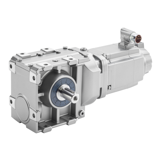
Page 21: Description
Description Overview The SIMOTICS S-1FG1 servo geared motor forms a single system comprising a mechanical gearbox and a compact, permanent-magnet synchronous motor. The available options, gearbox variants and encoders, together with the expanded product range, mean that the 1FG1 servo geared motors can be optimally adapted to any application. They therefore also satisfy the permanently increasing demands of state-of-the-art machine generations. -
Page 22: Technical Features And Ambient Conditions
If you wish to use special versions and design variants whose specifications vary from the motors described in this document, then contact your local Siemens office. If you have any questions regarding the intended usage, please contact your local Siemens office. - Page 23 Quality systems Siemens AG employs a quality management system that meets the requirements of ISO 9001 and ISO 14001. Certificates for SIMOTICS motors can be downloaded from the Internet at the following link: Certificates for SIMOTICS motors (https://support.industry.siemens.com/cs/ww/de/ps/13347/cert)
-
Page 24: General Technical Features Of The 1Fg1 Servo Geared Motor
Connectors for signals and power, can be rotated Holding brake PE holding brake (standard and with increased holding • torque) Spring-loaded brake (holding brake with increased • energy capability) S/R = signals/revolution SIMOTICS S-1FG1 servo geared motor Operating Instructions, 07/2019, A5E47360747B AA... -
Page 25: Environmental Conditions
DIN IEC 60721-3-3. The environmental effects and their limit values are defined in various classes in this standard. You can assign the SIMOTICS S-1FG1 servo geared motors to climate class 3K4 with the exception of the environmental factor "condensation". Condensation is not permissible. -
Page 26: Address Of Ce-Authorized Manufacturer
0.92 0.89 0.87 0.84 0.81 0.77 4000 0.89 0.87 0.84 0.81 0.77 0.74 The factors refer to the static torque M . You shift the S1 characteristic curve in parallel. SIMOTICS S-1FG1 servo geared motor Operating Instructions, 07/2019, A5E47360747B AA... -
Page 27: Structure Of The Article Number
The article number comprises a combination of digits and letters. You can find possible combinations in the Catalog D41 (https://support.industry.siemens.com/cs/document/109747093/catalog-d-41%3A-simotics-s- 1fg1-servo-geared-motors-helical-parallel-shaft-bevel-and-helical-worm-geared- motors?dti=0&lc=en-US). Note Note that not every theoretical combination is possible in practice. SIMOTICS S-1FG1 servo geared motor Operating Instructions, 07/2019, A5E47360747B AA... - Page 28 Motor shaft height 63 Motor shaft height 80 Motor shaft height 100 Motor length Motor length 0 Motor length 1 Motor length 2 Motor length 3 Motor length 4 Motor length 5 SIMOTICS S-1FG1 servo geared motor Operating Instructions, 07/2019, A5E47360747B AA...
- Page 29 • Flange-mounted design - for flange-mounted design see Chapter "Options" in Catalog D41 Housing flange-mounted design Gear ratio Options Coded Order code required - see Chapter "Options" in Catalog D41 SIMOTICS S-1FG1 servo geared motor Operating Instructions, 07/2019, A5E47360747B AA...
-
Page 30: Rating Plate Specifications Of The Servo Geared Motor
/ Nm 13 Certifications; EN 60034/UL/CE/EAC/CSA 26 Rated torque * For more information about the degree of protection, see Chapter "General technical features of the 1FG1 servo geared motor (Page 22)". SIMOTICS S-1FG1 servo geared motor Operating Instructions, 07/2019, A5E47360747B AA... -
Page 31: Type Designation Of The Gearbox
Torque arm Connection Feather key Shrink disk Hollow shaft with splines SIMOLOC Table 2- 5 Example of the type designation structure Example Gearbox type Transmission stage Shaft Mounting Connection Size SIMOTICS S-1FG1 servo geared motor Operating Instructions, 07/2019, A5E47360747B AA... -
Page 32: Mounting And Options
The following warning labels are attached to the 1FG1 servo geared motor. ① Warning symbol "Warning against hot surface" ② WEEE mark Dispose of the 1FG1 servo geared motor in accordance with WEEE Directive 2012/19/EU. SIMOTICS S-1FG1 servo geared motor Operating Instructions, 07/2019, A5E47360747B AA... -
Page 33: Cooling Of The Servo Geared Motor
This can cause unintended movements of the machine or installation resulting in death or serious injury. • Observe the permissible number of operating cycles. • Operate the motor only in conjunction with an intact brake. SIMOTICS S-1FG1 servo geared motor Operating Instructions, 07/2019, A5E47360747B AA... -
Page 34: Motor-Side Connection Of The Holding Brake
Since safe electrical isolation from the motor winding is guaranteed for the brake cable in the motor and the power cable is designed as an enforced insulation, no further protection circuits are required in this case. SIMOTICS S-1FG1 servo geared motor Operating Instructions, 07/2019, A5E47360747B AA... -
Page 35: Protective Circuitry For The Brake
= Direct current of the brake in A brake Note Integrate a protective circuit into the incoming cable. In this way, you avoid switching overvoltages and possible influence of the installation environment. See the figure below SIMOTICS S-1FG1 servo geared motor Operating Instructions, 07/2019, A5E47360747B AA... -
Page 36: Permanent-Magnet Brake
(electromagnetically opening system). It also works according to the closed-circuit principle. For the technical data, see Chapter "Configuring guide" in Catalog D41. SIMOTICS S-1FG1 servo geared motor Operating Instructions, 07/2019, A5E47360747B AA... - Page 37 • If the manual release handle cannot be placed in the vertical positon, shut down the installation or machine immediately. • Start the installation again only when proper functioning of the manual brake release is ensured. • Disassemble the manual release handle during normal operation. SIMOTICS S-1FG1 servo geared motor Operating Instructions, 07/2019, A5E47360747B AA...
- Page 38 Removing the manual release handle of the spring-loaded brake 1. Place the manual release handle in the vertical position 2. Remove the manual release handle. You have secured the spring-loaded brake against unintended actuation. ❒ SIMOTICS S-1FG1 servo geared motor Operating Instructions, 07/2019, A5E47360747B AA...
- Page 39 The width of the air gap indicates the wear state of the armature disk. The wider the air gap, the greater the wear on the armature disk. Figure 2-4 View from above SIMOTICS S-1FG1 servo geared motor Operating Instructions, 07/2019, A5E47360747B AA...
- Page 40 When the air gap reaches the value s , the wear limit of the brake has been reached. For continued functional safety, you must replace the brake. You cannot adjust the brake. Consult your Siemens representative. SIMOTICS S-1FG1 servo geared motor Operating Instructions, 07/2019, A5E47360747B AA...
-
Page 41: Increased Chemical Resistance
2.7.4 Increased chemical resistance SIMOTICS S-1FG1 servo geared motors are available in a version with increased chemical resistance. The relevant order code is N16. The paint system of these servo geared motors is resistant to numerous common cleaners and disinfectants. - Page 42 Description 2.7 Mounting and options SIMOTICS S-1FG1 servo geared motor Operating Instructions, 07/2019, A5E47360747B AA...
-
Page 43: Preparing For Use
● Upon receipt of the delivery, check immediately whether the items delivered are in accordance with the accompanying documents. Note Siemens will not accept any claims relating to items missing from the delivery and which are submitted at a later date. ● Register a complaint about –... -
Page 44: Transportation And Storage
Comply with the local national regulations for the transportation of servo geared motors. ● Transport and store the servo geared motors in the original packaging. ● Use suitable load suspension equipment when transporting and installing. ● Transport the servo geared motor carefully. SIMOTICS S-1FG1 servo geared motor Operating Instructions, 07/2019, A5E47360747B AA... - Page 45 1. Set the servo geared motor down on a hard, level surface. 2. Secure the servo geared motor against unintentional movements. You have set the servo geared motor down in a stable position. ❒ SIMOTICS S-1FG1 servo geared motor Operating Instructions, 07/2019, A5E47360747B AA...
-
Page 46: Storing The Servo Geared Motor
● Check the state of the dehydrating agent and replace when necessary. ● Record the preservation work so that all preservation coating can be removed from the servo geared motor prior to commissioning. SIMOTICS S-1FG1 servo geared motor Operating Instructions, 07/2019, A5E47360747B AA... -
Page 47: Mounting And Properties Of The Gearboxes
The shaft sealing rings on the output side prevent lubricant from escaping from the housing at the shaft outlet and prevent pollution from entering the housing. The optimum use of the seals depends on the ambient conditions and the lubricant being used. SIMOTICS S-1FG1 servo geared motor Operating Instructions, 07/2019, A5E47360747B AA... - Page 48 Noise not generated by the gearbox but emitted from it is not taken into consideration. Noise emitted by the drive and driven machines or the base is not taken into consideration. SIMOTICS S-1FG1 servo geared motor Operating Instructions, 07/2019, A5E47360747B AA...
-
Page 49: Mounting Positions
Identifying marking for oil drain, opposite side Table 3- 5 Symbols - Supplements Symbol Meaning A, B Output side A, output side B ② 2-stage gearbox ③ 3-stage gearbox Position of the connection plug SIMOTICS S-1FG1 servo geared motor Operating Instructions, 07/2019, A5E47360747B AA... -
Page 50: Two- And Three-Stage Helical Gearbox
Preparing for use 3.4 Mounting positions 3.4.1 Two- and three-stage helical gearbox Figure 3-1 Mounting positions for helical gearboxes Z and D, foot-mounted design, sizes 19 - 29, 2-stage and 3-stage SIMOTICS S-1FG1 servo geared motor Operating Instructions, 07/2019, A5E47360747B AA... - Page 51 Preparing for use 3.4 Mounting positions Figure 3-2 Mounting positions for helical gearboxes Z and D, foot-mounted design, sizes 39 - 129, 2-stage and 3-stage SIMOTICS S-1FG1 servo geared motor Operating Instructions, 07/2019, A5E47360747B AA...
- Page 52 Preparing for use 3.4 Mounting positions Figure 3-3 Mounting positions for helical gearboxes ZB and DB, foot, flange-mounted design, sizes 19 - 29, 2-stage and 3-stage SIMOTICS S-1FG1 servo geared motor Operating Instructions, 07/2019, A5E47360747B AA...
- Page 53 Preparing for use 3.4 Mounting positions Figure 3-4 Mounting positions for helical gearboxes ZB and DB, foot-, flange-mounted design, sizes 39 - 89, 2-stage and 3-stage SIMOTICS S-1FG1 servo geared motor Operating Instructions, 07/2019, A5E47360747B AA...
- Page 54 Preparing for use 3.4 Mounting positions Figure 3-5 Mounting positions for helical gearboxes DF and ZF (flange design), and DZ and ZZ (housing flange design), sizes 19 - 29, 2-stage and 3-stage SIMOTICS S-1FG1 servo geared motor Operating Instructions, 07/2019, A5E47360747B AA...
- Page 55 Preparing for use 3.4 Mounting positions Figure 3-6 Mounting positions for helical gearboxes DF and ZF (flange design), and DZ and ZZ (housing flange design), size 39, 2-stage and 3-stage SIMOTICS S-1FG1 servo geared motor Operating Instructions, 07/2019, A5E47360747B AA...
- Page 56 Preparing for use 3.4 Mounting positions Figure 3-7 Mounting positions for helical gearboxes DF and ZF (flange design), and DZ and ZZ (housing flange design), sizes 49 - 129, 2-stage and 3-stage SIMOTICS S-1FG1 servo geared motor Operating Instructions, 07/2019, A5E47360747B AA...
-
Page 57: Parallel Shaft Gearbox
Preparing for use 3.4 Mounting positions 3.4.2 Parallel shaft gearbox Figure 3-8 Mounting positions for parallel shaft gearboxes FZ and FD, foot-mounted design, sizes 19 - 29, 2-stage and 3-stage SIMOTICS S-1FG1 servo geared motor Operating Instructions, 07/2019, A5E47360747B AA... - Page 58 Preparing for use 3.4 Mounting positions Figure 3-9 Mounting positions for parallel shaft gearboxes FZ and FD, foot-mounted design, sizes 39 - 129, 2-stage and 3-stage SIMOTICS S-1FG1 servo geared motor Operating Instructions, 07/2019, A5E47360747B AA...
- Page 59 3.4 Mounting positions Figure 3-10 Mounting positions for parallel shaft gearboxes FZ.F and FD.F (flange design), and FZ.Z and FD.Z, (housing flange design), sizes 19 - 29, 2-stage and 3-stage SIMOTICS S-1FG1 servo geared motor Operating Instructions, 07/2019, A5E47360747B AA...
- Page 60 3.4 Mounting positions Figure 3-11 Mounting positions for parallel shaft gearboxes FZ.F and FD.F (flange design), and FZ.Z and FD.Z, (housing flange design), sizes 39 - 129, 2-stage and 3-stage SIMOTICS S-1FG1 servo geared motor Operating Instructions, 07/2019, A5E47360747B AA...
- Page 61 Preparing for use 3.4 Mounting positions Figure 3-12 Mounting positions for parallel shaft gearboxes FZAD and FDAD, shaft-mounted design, sizes 19 - 29, 2-stage and 3-stage SIMOTICS S-1FG1 servo geared motor Operating Instructions, 07/2019, A5E47360747B AA...
- Page 62 Preparing for use 3.4 Mounting positions Figure 3-13 Mounting positions for parallel shaft gearboxes FZAD and FDAD, shaft-mounted design, sizes 39 - 129, 2-stage and 3-stage SIMOTICS S-1FG1 servo geared motor Operating Instructions, 07/2019, A5E47360747B AA...
-
Page 63: Bevel Gearbox
Preparing for use 3.4 Mounting positions 3.4.3 Bevel gearbox Figure 3-14 Mounting positions for bevel gearbox B, foot-mounted design, sizes 19 - 29, 2-stage SIMOTICS S-1FG1 servo geared motor Operating Instructions, 07/2019, A5E47360747B AA... - Page 64 Preparing for use 3.4 Mounting positions Figure 3-15 Mounting positions for bevel gearbox B, foot-mounted design, sizes 39 - 49, 2-stage SIMOTICS S-1FG1 servo geared motor Operating Instructions, 07/2019, A5E47360747B AA...
- Page 65 Preparing for use 3.4 Mounting positions Figure 3-16 Mounting positions for bevel gearbox B.Z (flange design), or B.Z (housing flange design), sizes 19 - 29, 2-stage SIMOTICS S-1FG1 servo geared motor Operating Instructions, 07/2019, A5E47360747B AA...
- Page 66 Preparing for use 3.4 Mounting positions Figure 3-17 Mounting positions for bevel gearbox B.Z (flange design), or B.Z (housing flange design), sizes 39 - 49, 2-stage SIMOTICS S-1FG1 servo geared motor Operating Instructions, 07/2019, A5E47360747B AA...
- Page 67 Preparing for use 3.4 Mounting positions Figure 3-18 Mounting positions for bevel gearbox BAD, shaft-mounted design, sizes 19 - 29, 2-stage SIMOTICS S-1FG1 servo geared motor Operating Instructions, 07/2019, A5E47360747B AA...
- Page 68 Preparing for use 3.4 Mounting positions Figure 3-19 Mounting positions for bevel gearbox BAD, shaft-mounted design, sizes 39 - 49, 2-stage SIMOTICS S-1FG1 servo geared motor Operating Instructions, 07/2019, A5E47360747B AA...
- Page 69 Preparing for use 3.4 Mounting positions Figure 3-20 Mounting positions for bevel gearbox K, foot-mounted design, sizes 39 - 149, 3-stage SIMOTICS S-1FG1 servo geared motor Operating Instructions, 07/2019, A5E47360747B AA...
- Page 70 Preparing for use 3.4 Mounting positions Figure 3-21 Mounting positions for bevel gearbox K.F (flange design), and KAZ (housing flange design), sizes 39 - 149, 3-stage SIMOTICS S-1FG1 servo geared motor Operating Instructions, 07/2019, A5E47360747B AA...
- Page 71 Preparing for use 3.4 Mounting positions Figure 3-22 Mounting positions for bevel gearbox KAD, shaft-mounted design, sizes 39 - 149, 3-stage SIMOTICS S-1FG1 servo geared motor Operating Instructions, 07/2019, A5E47360747B AA...
-
Page 72: Helical Worm Gearbox
Preparing for use 3.4 Mounting positions 3.4.4 Helical worm gearbox Figure 3-23 Mounting positions for helical worm gearbox C, foot-mounted design, sizes 19 - 29, 2-stage SIMOTICS S-1FG1 servo geared motor Operating Instructions, 07/2019, A5E47360747B AA... - Page 73 Preparing for use 3.4 Mounting positions Figure 3-24 Mounting positions for helical worm gearbox C, foot-mounted design, sizes 39 - 89, 2-stage SIMOTICS S-1FG1 servo geared motor Operating Instructions, 07/2019, A5E47360747B AA...
- Page 74 Preparing for use 3.4 Mounting positions Figure 3-25 Mounting positions for helical worm gearbox CF (flange design), and CAZ (housing flange design), sizes 19 - 29, 2-stage SIMOTICS S-1FG1 servo geared motor Operating Instructions, 07/2019, A5E47360747B AA...
- Page 75 Preparing for use 3.4 Mounting positions Figure 3-26 Mounting positions for helical worm gearbox CF (flange design), and CAZ (housing flange design), sizes 39 - 89, 2-stage SIMOTICS S-1FG1 servo geared motor Operating Instructions, 07/2019, A5E47360747B AA...
- Page 76 Preparing for use 3.4 Mounting positions Figure 3-27 Mounting positions for helical worm gearbox CAD, shaft-mounted design, sizes 19 - 29, 2-stage SIMOTICS S-1FG1 servo geared motor Operating Instructions, 07/2019, A5E47360747B AA...
- Page 77 Preparing for use 3.4 Mounting positions Figure 3-28 Mounting positions for helical worm gearbox CAD, shaft-mounted design, sizes 39 - 89, 2-stage SIMOTICS S-1FG1 servo geared motor Operating Instructions, 07/2019, A5E47360747B AA...
- Page 78 Preparing for use 3.4 Mounting positions SIMOTICS S-1FG1 servo geared motor Operating Instructions, 07/2019, A5E47360747B AA...
-
Page 79: Mounting
• When transporting or storing permanent magnet motors always use the original packing materials with the warning labels attached. • Clearly mark the storage locations with the appropriate warning labels. • IATA regulations must be observed when transporting by air. SIMOTICS S-1FG1 servo geared motor Operating Instructions, 07/2019, A5E47360747B AA... - Page 80 Damaged components impair the correct function of the gearbox If any components are damaged, the correct function of the gearbox will no longed be ensured. Do not install any damaged gearbox components. SIMOTICS S-1FG1 servo geared motor Operating Instructions, 07/2019, A5E47360747B AA...
-
Page 81: Checklists For Mounting
Checklist (1) - general checks Check Are all of the necessary components of the configured drive line-up available, correctly dimensioned, installed and connected? Are the environmental conditions in the permissible range? SIMOTICS S-1FG1 servo geared motor Operating Instructions, 07/2019, A5E47360747B AA... -
Page 82: Mounting Instructions
● If the motor is installed vertically with the end of the shaft facing up, ensure that no liquid can enter the upper bearing. ● After installation, remove the lifting eyes or tighten them. SIMOTICS S-1FG1 servo geared motor Operating Instructions, 07/2019, A5E47360747B AA... - Page 83 The values given in the table "Tightening torque for screw plugs and valves" also apply for all metal valves, e.g. oil drain vales, pressure vent valves. Plastic vent filters and oil sight glasses must be tightened manually. SIMOTICS S-1FG1 servo geared motor Operating Instructions, 07/2019, A5E47360747B AA...
-
Page 84: Gearbox With Foot Mounting
B, K FD/FZ Size 19, 29, 39 29, 39 B19, B29, B39 B49, K39, K49 39, 49 49, 59, 69 69, 79 K69, K79 79, 89 89, 109 K109 K129 K149 SIMOTICS S-1FG1 servo geared motor Operating Instructions, 07/2019, A5E47360747B AA... -
Page 85: Gearbox With Flange Fastening
Mounting 4.5 Gearbox with flange fastening Gearbox with flange fastening Note Siemens AG recommends an anaerobic adhesive to enhance the friction lock between flange and mounting surface. Table 4- 6 Thread size of the fastening bolt Thread size Flange Helical gearboxes... -
Page 86: Gearboxes In Foot Or Flange Version
Unless otherwise specified, use a torch or a furnace to heat the input and output elements inductively. Use the center holes in the shaft end faces. Use a fitting device to fit the input or output elements. Figure 4-1 Example of a fitting device SIMOTICS S-1FG1 servo geared motor Operating Instructions, 07/2019, A5E47360747B AA... - Page 87 3. Fit the drive input and output elements to the shafts. 4. Secure the input or output elements, if provided. You have now fitted the input or output element. ❒ SIMOTICS S-1FG1 servo geared motor Operating Instructions, 07/2019, A5E47360747B AA...
-
Page 88: Mounting The Protection Cover
5. Place the washers on the screws ② 6. Screw on the protection cover 7. Protect all remaining bare areas with a suitable permanent anti-corrosive agent. You have now installed the protection cover for operation. ❒ SIMOTICS S-1FG1 servo geared motor Operating Instructions, 07/2019, A5E47360747B AA... -
Page 89: Installing And Removing The Shaft-Mounted Gearbox
Mounting the hollow shaft with feather key Instead of the nut and threaded spindle shown in the diagram, other types of equipment such as hydraulic lifting equipment may be used. SIMOTICS S-1FG1 servo geared motor Operating Instructions, 07/2019, A5E47360747B AA... - Page 90 Excessive forces can occur during removal of the hollow shaft via the housing, and can damage the bearings and housing. Remove the hollow shaft without placing it under stress or bending it. SIMOTICS S-1FG1 servo geared motor Operating Instructions, 07/2019, A5E47360747B AA...
- Page 91 2. Drive out the machine shaft using the disk , threaded block , feather key ⑤ ④ threaded spindle and hexagon nuts You have now removed the hollow shaft with feather key. ❒ SIMOTICS S-1FG1 servo geared motor Operating Instructions, 07/2019, A5E47360747B AA...
- Page 92 34.9 39.9 29.9 K, F, C 34.9 39.9 K, F, C 39.9 44.9 K, F 39.9 K, F, C 49.9 53.5 59.9 K, F 59.9 K, F 69.9 74.5 89.9 SIMOTICS S-1FG1 servo geared motor Operating Instructions, 07/2019, A5E47360747B AA...
-
Page 93: Mounting Or Removing The Hollow Shaft With Shrink Disk
Danger of deformation of the hollow shaft caused by tightening the tightening bolts Tightening the tightening bolts before fitting the machine shaft can cause deformation of the hollow shaft. 1. Install the machine shaft. 2. Tighten the tightening bolts. SIMOTICS S-1FG1 servo geared motor Operating Instructions, 07/2019, A5E47360747B AA... - Page 94 • Do not use mounting paste at the point of force transmission between the hollow shaft and the machine shaft. Note Apply a thin layer of grease to the shrink disk seat on the hollow shaft. SIMOTICS S-1FG1 servo geared motor Operating Instructions, 07/2019, A5E47360747B AA...
- Page 95 5. Attach the rubber cover or protection cover included in the scope of supply, see Mounting the protection cover (Page 86). You have now mounted the shrink disk. ❒ SIMOTICS S-1FG1 servo geared motor Operating Instructions, 07/2019, A5E47360747B AA...
- Page 96 μ = 0.04. 2. Use a paste containing MoS to grease the bolts, applying the paste to the thread and underneath the head. You have now cleaned the shrink disk. ❒ SIMOTICS S-1FG1 servo geared motor Operating Instructions, 07/2019, A5E47360747B AA...
-
Page 97: Installing Or Removing The Simoloc Connection
Type of the provided oil: CLP VG 68 DIN 51517-3 Note ⑤ Place the thrust collar at the correct position as in the delivery state. Note ⑦ Before installing the SIMOLOC, mount the torque arms on the gearbox. SIMOTICS S-1FG1 servo geared motor Operating Instructions, 07/2019, A5E47360747B AA... - Page 98 Tapered bushing ⑩ Tightening bolt for the tapered bushing ⑪ Protection cover / cover cap ⑫ ⑩ Threaded hole for the tightening bolt during disassembly Figure 4-6 Installing the SIMOLOC connection SIMOTICS S-1FG1 servo geared motor Operating Instructions, 07/2019, A5E47360747B AA...
- Page 99 (Page 100) ⑪ 13.Attach the rubber cover or protection cover included in the scope of delivery. See Mounting the protection cover (Page 86) You have attached the SIMOLOC connection. ❒ SIMOTICS S-1FG1 servo geared motor Operating Instructions, 07/2019, A5E47360747B AA...
- Page 100 ⑩ 5. Remove the bolts ⑨ 6. Remove the tapered bushing ① 7. Lower the gearbox from the machine shaft You have now removed the SIMOLOC connection. ❒ SIMOTICS S-1FG1 servo geared motor Operating Instructions, 07/2019, A5E47360747B AA...
-
Page 101: Mounting The Hollow Shaft With Splines
Tighten the bolts with the specified torque. You have now mounted the hollow shaft. ❒ Table 4- 17 Tightening torque for setscrews Thread size Tightening torque in Nm SIMOTICS S-1FG1 servo geared motor Operating Instructions, 07/2019, A5E47360747B AA... -
Page 102: Torque Arms With Shaft-Mounted Gearboxes
We recommend using pretensioned, damping rubber elements. Fixing accessories such as brackets, bolts, nuts, etc., are not included in the scope of supply. Figure 4-8 Mounting suggestion for torque arms on F.29 - F.149 SIMOTICS S-1FG1 servo geared motor Operating Instructions, 07/2019, A5E47360747B AA... - Page 103 2. Use two nuts to secure the screw connection (lock nuts). 3. Tighten the screws until the rubber buffers are pretensioned to the dimension l1x. You have now mounted the torque arm. ❒ SIMOTICS S-1FG1 servo geared motor Operating Instructions, 07/2019, A5E47360747B AA...
- Page 104 2. Tighten the bolts to the specified torque. You have now mounted the torque arm. ❒ Table 4- 19 Tightening torque for screws of strength class 8.8 Thread size Tightening torque in Nm 2 600 SIMOTICS S-1FG1 servo geared motor Operating Instructions, 07/2019, A5E47360747B AA...
-
Page 105: Mount The Oil Expansion Unit
B 39 - 49 C 69 - 89 Note Selecting the oil expansion unit Contact the Siemens Service Center for final selection of the oil expansion unit. The unit is supplied as a mounting kit. Note Attaching the oil expansion unit before commissioning Before commissioning the gearbox, replace the pressure vent valve that is already installed with the provided oil expansion unit. - Page 106 6. Screw reduction piece 1460 with 35 Nm torque onto the lower side of tank 1451. 7. Press one end of hose 1463 onto angular hose nozzle 1461. 8. Fix hose end 1463 with clip 1462. SIMOTICS S-1FG1 servo geared motor Operating Instructions, 07/2019, A5E47360747B AA...
- Page 107 15.Screw angular hose nozzle 1464 with 35 Nm tightening torque onto reduction piece 1466. 16.Tighten angular hose nozzle 1461 with a torque of 35 Nm. You have now installed the oil expansion unit. ❒ Note Replace the vent valve of the unit yearly. SIMOTICS S-1FG1 servo geared motor Operating Instructions, 07/2019, A5E47360747B AA...
-
Page 108: Vibration Response
The vibration acceleration is evaluated in the frequency band from 10 to 2000 Hz. Whereby, the maximum peak value in the time range is considered. To evaluate the vibration velocity, the measuring equipment must fulfill the requirements of ISO 2954. SIMOTICS S-1FG1 servo geared motor Operating Instructions, 07/2019, A5E47360747B AA... -
Page 109: Connecting
5. Secure the energy sources against switching on again. 6. Ensure that the correct machine is completely interlocked. After you have completed the work, restore the operational readiness in the inverse sequence. SIMOTICS S-1FG1 servo geared motor Operating Instructions, 07/2019, A5E47360747B AA... -
Page 110: Permissible Line System Types
Circuit diagram The circuit diagram contains information about wiring and connecting the motor winding. Figure 5-1 Circuit diagram SIMOTICS S-1FG1 servo geared motor Operating Instructions, 07/2019, A5E47360747B AA... -
Page 111: System Integration
• Only grounded personnel with grounded tools may touch the component connections. • Heed the EMC information provided by the manufacturer of the converter. ● Use prefabricated cables from SIEMENS (not in the scope of delivery). These cables reduce installation costs and increase operational reliability (see the Product Information). - Page 112 Table 5- 2 Derating factors for power and signal cables Ambient air temperature in °C Derating factor according to EN 60204-1, Table D1 1.15 1.08 1.00 0.91 0.82 0.71 0.58 SIMOTICS S-1FG1 servo geared motor Operating Instructions, 07/2019, A5E47360747B AA...
-
Page 113: Rotating The Connector At The Motor
Table 5- 3 Rotation range of the power connector Motor Angle α Angle β Connector size Drawing 1FG1□□□-□□C□□ 122° 208° 1FG1□□□-□□D□□ 1FG1□□□-□□E□□ 135° 195° 1FG1□□□-□□F□□ 1FG1□□□-□□G□□ 1FG1□□□-□□F□□ 195° 140° 1FG1□□□-□□G□□ SIMOTICS S-1FG1 servo geared motor Operating Instructions, 07/2019, A5E47360747B AA... - Page 114 Max. torque when rotating Connectors Max. torque when rotating Power connector M23 12 Nm Power connector M40 20 Nm Signal connector (without DRIVE-CLiQ) 12 Nm Signal connector (with DRIVE-CLiQ) 8 Nm SIMOTICS S-1FG1 servo geared motor Operating Instructions, 07/2019, A5E47360747B AA...
-
Page 115: Power Connection
The motors are connected to the converter system via a DRIVE-CLiQ interface. We recommend the following two variants for the DRIVE-CLiQ connection: 10-way RJ45 socket Round connector M17 1 10-way RJ45 socket 1 round connector M17 SIMOTICS S-1FG1 servo geared motor Operating Instructions, 07/2019, A5E47360747B AA... - Page 116 • Heed the EMC information provided by the manufacturer of the converter. The motor and the Motor Module are connected via a MOTION-CONNECT cable, see Instructions for handling the RJ45 connector (Page 119) Figure 5-2 Encoder interface with DRIVE-CLiQ SIMOTICS S-1FG1 servo geared motor Operating Instructions, 07/2019, A5E47360747B AA...
-
Page 117: Motors Without A Drive-Cliq Interface
SINAMICS S120 drive system. The motor is connected to the SMC via a signal cable. The SMC is connected to the motor via a MOTION-CONNECT cable. Figure 5-4 Encoder interface without DRIVE-CLiQ SIMOTICS S-1FG1 servo geared motor Operating Instructions, 07/2019, A5E47360747B AA... -
Page 118: Design Of The Signal Connectors
Note The cable shielding, made up of as many strands as possible, must have a high electrical conductivity. Braided shields made of copper or aluminum are well suited. SIMOTICS S-1FG1 servo geared motor Operating Instructions, 07/2019, A5E47360747B AA... - Page 119 , each cable with separate shielding BD1+ and BD2- = brake cable without lettering, 1.5 mm , shielded together PE = protective conductor Cable shield Conductor designations Recommended length of the cable ends: 105 mm SIMOTICS S-1FG1 servo geared motor Operating Instructions, 07/2019, A5E47360747B AA...
- Page 120 ● Establish the connection through a larger surface area so that high-frequency currents are suitably discharged. Establish a 360° connection at the converter and at the motor, for instance using EMC cable glands at the cable entries. SIMOTICS S-1FG1 servo geared motor Operating Instructions, 07/2019, A5E47360747B AA...
-
Page 121: Instructions For Handling The Rj45 Connector
The DRIVE-CLiQ connection method with the RJ45 connector has the following components: DRIVE-CLiQ plug with RJ45 plug DRIVE-CLiQ socket with RJ45 socket ① Rotatable locking ring ② Tabs (2, opposite each other) ③ Latches (2, opposite each other) SIMOTICS S-1FG1 servo geared motor Operating Instructions, 07/2019, A5E47360747B AA... - Page 122 In the "locked" position, the tabs are flush against the connector. ① Locking ring in the "locked" position 2. Insert the connector into the RJ45 socket of the Sensor Module. ① The locking ring remains in the "locked" position. SIMOTICS S-1FG1 servo geared motor Operating Instructions, 07/2019, A5E47360747B AA...
- Page 123 The correct DRIVE-CLiQ connection is made when ● the locking ring is in the "locked" position, ● both tabs are engaged in both latches. You have now made a DRIVE-CLiQ connection. ❒ SIMOTICS S-1FG1 servo geared motor Operating Instructions, 07/2019, A5E47360747B AA...
-
Page 124: Handling The Quick-Action Locking
You can also connect quick-connection cables with SPEED-CONNECT to motor connectors as conventional cables with screw locks (fully threaded). Note We recommend cables with SPEED-CONNECT because they are easier to use. SIMOTICS S-1FG1 servo geared motor Operating Instructions, 07/2019, A5E47360747B AA... - Page 125 (position B) Minimum locking Maximum locking up to the end stop Note A secure connection is only guaranteed from position A onward. You have established a secure connection. ❒ SIMOTICS S-1FG1 servo geared motor Operating Instructions, 07/2019, A5E47360747B AA...
-
Page 126: Routing Cables In A Damp Environment
If the motor is mounted in a humid environment, the power and signal cables must be routed as shown in the following figure. Figure 5-5 Routing cables in a damp environment SIMOTICS S-1FG1 servo geared motor Operating Instructions, 07/2019, A5E47360747B AA... -
Page 127: Commissioning
Unintentional starting of the converter can cause death or severe injury. • Make sure that the converter cannot be started accidentally. • Post a warning notice to this effect at the point where the switch is located. SIMOTICS S-1FG1 servo geared motor Operating Instructions, 07/2019, A5E47360747B AA... - Page 128 The motor can be damaged if operated at inadmissible speeds. • Ensure that the maximum permissible speed is not exceeded. Realize this using a suitable control system or activate the speed monitoring function in the drive. SIMOTICS S-1FG1 servo geared motor Operating Instructions, 07/2019, A5E47360747B AA...
-
Page 129: Checklists For Commissioning
Is the motor type to be commissioned known? (e.g. 1FG1 _ _ _ – _ _ _ _ _ – _ _ _ _) Are the environmental conditions in the permissible range? SIMOTICS S-1FG1 servo geared motor Operating Instructions, 07/2019, A5E47360747B AA... - Page 130 For motors that were stored, were the storage conditions according to the "Storage" sec- tion and the bearing replacement intervals according to the "Bearing replacement inter- vals" section complied with? SIMOTICS S-1FG1 servo geared motor Operating Instructions, 07/2019, A5E47360747B AA...
-
Page 131: Preparing Commissioning
● Commission the motor with an appropriate commissioning tool, e.g. "Drive ES" or "STARTER". ● Follow the steps of the commissioning tool. You have commissioned the motor. ❒ Switching off ● Switch off the motor at the frequency converter. SIMOTICS S-1FG1 servo geared motor Operating Instructions, 07/2019, A5E47360747B AA... -
Page 132: Switching On And Switching Off
3. Check the function of the safety equipment. 4. Check whether the motor reaches the required parameters You have switched on the motor. ❒ Switching off ● Switch off the motor at the frequency converter. SIMOTICS S-1FG1 servo geared motor Operating Instructions, 07/2019, A5E47360747B AA... -
Page 133: Operation
The maximum torque is 2dyn specified on the rating plate. Impermissible torques can cause damage to gearboxes. • Using the controller, ensure the maximum torque is not exceeded. SIMOTICS S-1FG1 servo geared motor Operating Instructions, 07/2019, A5E47360747B AA... -
Page 134: Switching On And Switching Off
3. Check the function of the safety equipment. 4. Check whether the motor reaches the required parameters You have switched on the motor. ❒ Switching off ● Switch off the motor at the frequency converter. SIMOTICS S-1FG1 servo geared motor Operating Instructions, 07/2019, A5E47360747B AA... -
Page 135: Operation
● Store the geared motor according to the instructions in chapter Storing the servo geared motor (Page 44). ● Refer to the section Switching on and switching off (Page 130) before recommissioning the motor SIMOTICS S-1FG1 servo geared motor Operating Instructions, 07/2019, A5E47360747B AA... - Page 136 Operation 7.4 Measures for longer non-operational periods SIMOTICS S-1FG1 servo geared motor Operating Instructions, 07/2019, A5E47360747B AA...
-
Page 137: Faults
• In this regard, observe the relevant chapter in the documentation associated with the components of the complete drive system • Even in test operation, never disable protective functions or devices SIMOTICS S-1FG1 servo geared motor Operating Instructions, 07/2019, A5E47360747B AA... - Page 138 Consult the manufacturer Poor alignment Align machine set, check coupling. Coupled machine not balanced Rebalance coupled machine. Mechanical shocks from coupled machine Inspect coupled machine. Uneven gearbox operation Repair the gearbox. SIMOTICS S-1FG1 servo geared motor Operating Instructions, 07/2019, A5E47360747B AA...
- Page 139 Flexible elements worn (e.g. on cou- Replace flexible elements. plings). If the fault still cannot be resolved after taking the measures stated above, please contact the manufacturer or the Siemens Service Center. SIMOTICS S-1FG1 servo geared motor Operating Instructions, 07/2019, A5E47360747B AA...
- Page 140 Faults SIMOTICS S-1FG1 servo geared motor Operating Instructions, 07/2019, A5E47360747B AA...
-
Page 141: Service And Maintenance
7. Make sure that the machine is completely locked ... and that you have the right machine. After you have completed the work, restore operational readiness by performing the above steps in the reverse order. SIMOTICS S-1FG1 servo geared motor Operating Instructions, 07/2019, A5E47360747B AA... - Page 142 • If using chemical cleaning agents, observe the instructions and any warnings provided in the relevant safety data sheet. Chemical cleaning agents must be suitable for use with the machine's components, particularly where plastic components are concerned. SIMOTICS S-1FG1 servo geared motor Operating Instructions, 07/2019, A5E47360747B AA...
- Page 143 • Use only perfectly functioning hoisting and load suspension equipment dimensioned to carry the motor load. • Do not stand under suspended loads or in their slewing range. • When placing down the motor, ensure that it cannot roll. SIMOTICS S-1FG1 servo geared motor Operating Instructions, 07/2019, A5E47360747B AA...
-
Page 144: Inspection And Maintenance
● Adapt the maintenance intervals to match the local conditions, such as pollution/dirt, switching frequency, load, etc. ● Perform the following maintenance measures as specified in the table. Maintenance and repair of the geared motor can be performed by Siemens Service Centers throughout the world. Consult your Siemens representative (http://www.siemens.com/industry/contact) if you... - Page 145 Changing the oil and the roller Changing oil (Page 148) bearing grease in the gearbox Change the roller bearing grease (Page 152) SIMOTICS S-1FG1 servo geared motor Operating Instructions, 07/2019, A5E47360747B AA...
-
Page 146: Thread Sizes And Tightening Torques For Fastening Bolts
The general tolerance for the tightening torque is 10%. The tightening torque is based on a friction coefficient of μ = 0.14. Table 9- 2 Tightening torques for fastening bolts Thread size Tightening torque at strength class in Nm 10.9 12.9 1000 1200 SIMOTICS S-1FG1 servo geared motor Operating Instructions, 07/2019, A5E47360747B AA... -
Page 147: Bearing Replacement Interval
In the case of greater temperature differences and filling quantities, the volume can vary by several liters. • Check the oil level approximately 30 minutes after switching off the converter and while it is still slightly warm. SIMOTICS S-1FG1 servo geared motor Operating Instructions, 07/2019, A5E47360747B AA... - Page 148 5. Check the state of the sealing ring on the sealing element. Replace the sealing element if the sealing ring is damaged. 6. After checking, seal the gearbox immediately using the sealing element. You have now checked the oil level in the gearbox housing. ❒ SIMOTICS S-1FG1 servo geared motor Operating Instructions, 07/2019, A5E47360747B AA...
-
Page 149: Checking The Oil Level Using The Oil Sight Glass (Optional)
7. Check the oil for the changes described above. Change the oil immediately if you determine any changes, see chapter "Changing the oil (Page 148)". You have now checked the oil quality. ❒ SIMOTICS S-1FG1 servo geared motor Operating Instructions, 07/2019, A5E47360747B AA... -
Page 150: Changing The Oil
• Carefully close the oil bore holes after regulating the oil level. Note When changing the oil, use the same oil type as that given on the information plate on the gearbox if possible. SIMOTICS S-1FG1 servo geared motor Operating Instructions, 07/2019, A5E47360747B AA... - Page 151 This makes the required complete draining of mineral oil from the gearbox extremely difficult. Note After the second flush, we recommend that an appropriate analysis institute checks the quality of the flushed fluid. SIMOTICS S-1FG1 servo geared motor Operating Instructions, 07/2019, A5E47360747B AA...
- Page 152 7. After flushing, immediately seal the gearbox using the sealing element. 8. Repeat this step for the second flushing. You have now flushed the gearbox twice and can pour in the new oil. ❒ SIMOTICS S-1FG1 servo geared motor Operating Instructions, 07/2019, A5E47360747B AA...
- Page 153 6. After filling with oil, seal the gearbox immediately using the sealing element. 7. Screw in the vent plug. You have now filled up the gearbox with oil. ❒ SIMOTICS S-1FG1 servo geared motor Operating Instructions, 07/2019, A5E47360747B AA...
-
Page 154: Recommended Oil Types
The quality of the oil used must comply with the requirements laid down in the BA 7300 Operating Instructions; otherwise, the Siemens warranty is null and void. We recommend the use of an approved gearbox lubricant specified in the T 7300 (http://support.automation.siemens.com/WW/view/de/44231658) Operating Instructions. -
Page 155: Service Life Of The Lubricants
In the case of bearings on the output shaft or intermediate shafts, the grease quantity must fill 2/3, and in the case of bearings on the input side, 1/3 of the space between the rolling elements. Note Consult your Siemens representative (http://www.siemens.com/industry/contact) if you have any questions 9.2.4.7 Service life of the lubricants... -
Page 156: Recommended Lubricants
Use only lubricants with USDA (United States Department of Agriculture) H1 / H2 approval for deployment in the foodstuff or pharmaceutical industry. The released and recommended lubricants are listed in the T 7300 Operating Instructions. SIMOTICS S-1FG1 servo geared motor Operating Instructions, 07/2019, A5E47360747B AA... - Page 157 Use an approved gearbox lubricant from chapter "Recommended oil types (Page 152)". These oils have been tested and satisfy the requirements. Note Before use, check that the selected lubricating oil is still recommended by Siemens. Consult your Siemens representative, if applicable. SIMOTICS S-1FG1 servo geared motor...
-
Page 158: Oil Quantities
If significant leaks occur, or if a leak persists after the run-in period, replace the shaft sealing ring. This prevents follow-on damage. Shaft sealing rings are subject to natural wear. The service life depends on the rated conditions. SIMOTICS S-1FG1 servo geared motor Operating Instructions, 07/2019, A5E47360747B AA... -
Page 159: Cleaning The Gearbox
• Do not use high-pressure cleaning equipment to clean the geared motor. • When cleaning, do not use any tools with sharp edges. Switch off the power supply to the converter prior to cleaning. SIMOTICS S-1FG1 servo geared motor Operating Instructions, 07/2019, A5E47360747B AA... -
Page 160: Checking Tightness Of Fastening Bolts
(Page 144) Corrective maintenance The Siemens Service Center Bad Neustadt and other regional service sites throughout the world can handle or organize the maintenance/repair of the servo geared motors. Consult your regional Siemens contact person if you require this service. -
Page 161: Decommissioning And Disposal
7. Make sure that the machine is completely locked ... and that you have the right machine. After you have completed the work, restore operational readiness by performing the above steps in the reverse order. SIMOTICS S-1FG1 servo geared motor Operating Instructions, 07/2019, A5E47360747B AA... - Page 162 The machine partially comprises heavy individual components. When removing the machine, these components can fall. This can result in death, serious injury or material damage. • Secure the machine components that are being released so that they cannot fall. SIMOTICS S-1FG1 servo geared motor Operating Instructions, 07/2019, A5E47360747B AA...
- Page 163 • Have materials on hand to soak up leaked liquids and prevent areas from being slippery. Dismantling the motor Note The rotor in a motor containing permanent magnets must only be removed by the manufacturer. • Contact the Siemens Service Center (https://support.industry.siemens.com/cs/?lc=de- WW). SIMOTICS S-1FG1 servo geared motor Operating Instructions, 07/2019, A5E47360747B AA...
-
Page 164: Decommissioning
Dismantling the motor Note The rotor in a motor containing permanent magnets must only be removed by the manufacturer. Contact the Siemens Service Center (https://support.industry.siemens.com/cs/?lc=de-WW). 10.3 Disposal Recycling and disposal For environmentally-friendly recycling and disposal of your old device, please contact a company certified for the disposal of waste electrical and electronic equipment, and dispose of the old device as prescribed in the respective country of use. -
Page 165: Appendix
Appendix Certificate for the "PS Premium" painting system from ECOLAB Figure A-1 Certificate_option_N16_page1 SIMOTICS S-1FG1 servo geared motor Operating Instructions, 07/2019, A5E47360747B AA... - Page 166 Appendix A.1 Certificate for the "PS Premium" painting system from ECOLAB Figure A-2 Certificate_option_N16_page2 SIMOTICS S-1FG1 servo geared motor Operating Instructions, 07/2019, A5E47360747B AA...
-
Page 167: Ecolab Cleaning Recommendation
Appendix A.2 ECOLAB cleaning recommendation ECOLAB cleaning recommendation Figure A-3 ECOLAB cleaning recommendation for option N16 SIMOTICS S-1FG1 servo geared motor Operating Instructions, 07/2019, A5E47360747B AA... -
Page 169: Index
Technical Support, 5 Correct usage, 20 Tightening torques, 80 Training, 5 DRIVE-CLiQ interface, 113 Faults, 136 Holding brake, 31 Hotline, 5 Increased chemical resistance, 39 Inspection and maintenance, 139 Maintenance intervals, 142 SIMOTICS S-1FG1 servo geared motor Operating Instructions, 07/2019, A5E47360747B AA...
Need help?
Do you have a question about the SIMOTICS S-1FG1 and is the answer not in the manual?
Questions and answers