
Related Manuals for Siemens SIMOTICS S-1FT7


Summary of Contents for Siemens SIMOTICS S-1FT7
- Page 1 Configuration Manual SIMOTICS SIMOTICS S-1FT7 synchronous motors For SINAMICS S120 Edition 09/2018 www.siemens.com...
- Page 3 Introduction Fundamental safety ___________________ instructions ___________________ Description of the motors SIMOTICS ___________________ Mechanical properties Drive technology S-1FT7 synchronous motors ___________________ Motor components and options ___________________ Configuration Configuration Manual Technical data and ___________________ characteristic curves ___________________ Preparation for use ___________________ Electrical connection Assembly ___________________ drawings/dimension sheets...
- Page 4 Note the following: WARNING Siemens products may only be used for the applications described in the catalog and in the relevant technical documentation. If products and components from other manufacturers are used, these must be recommended or approved by Siemens. Proper transport, storage, installation, assembly, commissioning, operation and maintenance are required to ensure that the products operate safely and without any problems.
-
Page 5: Introduction
Planning and configuration phase My support The following link provides information on how to create your own individual documentation based on Siemens content, and adapt it for your own machine documentation: My support (https://support.industry.siemens.com/My/de/en/documentation) S-1FT7 synchronous motors Configuration Manual, 09/2018, A5E45099423B AA... - Page 6 Products (http://www.siemens.com/motioncontrol) Websites of third parties This publication contains hyperlinks to websites of third parties. Siemens does not take any responsibility for the contents of these websites or adopt any of these websites or their contents as their own, because Siemens does not control the information on these websites and is also not responsible for the contents and information provided there.
- Page 7 Introduction S-1FT7 synchronous motors Configuration Manual, 09/2018, A5E45099423B AA...
-
Page 9: Table Of Contents
Table of contents Introduction ............................. 3 Fundamental safety instructions ......................11 General safety instructions ..................... 11 Equipment damage due to electric fields or electrostatic discharge ........16 Industrial security ........................17 Residual risks of power drive systems ..................19 Description of the motors ........................21 Highlights and benefits...................... - Page 10 Table of contents Radial eccentricity, concentricity and axial eccentricity ............61 Balancing ..........................62 3.10 Vibration response ......................... 62 3.11 Noise emission ........................64 3.12 Bearing change interval ......................64 3.13 Service and inspection intervals .................... 65 Motor components and options ......................67 Motor components .........................
- Page 11 Table of contents 5.2.3 3. Definition of the load, calculation of the maximum load torque and determination of the motor ..........................110 Dimensioning the gearbox ....................117 Brake resistances (armature short-circuit braking) ............... 120 5.4.1 Description of function braking resistor................. 120 5.4.2 Dimensioning of braking resistors ..................
- Page 12 Table of contents 6.3.3.10 1FT7108-_W ........................312 6.3.4 1FT7 High Dynamic - natural cooling................... 318 6.3.4.1 1FT7087-_A ......................... 318 6.3.4.2 1FT7117-_A ......................... 320 6.3.5 1FT7 High Dynamic - forced ventilation ................324 6.3.5.1 1FT7065-_S ......................... 324 6.3.5.2 1FT7067-_S ......................... 328 6.3.5.3 1FT7085-_S .........................
-
Page 13: Fundamental Safety Instructions
Fundamental safety instructions General safety instructions WARNING Electric shock and danger to life due to other energy sources Touching live components can result in death or severe injury. • Only work on electrical devices when you are qualified for this job. •... - Page 14 Fundamental safety instructions 1.1 General safety instructions WARNING Electric shock due to damaged motors or devices Improper handling of motors or devices can damage them. Hazardous voltages can be present at the enclosure or at exposed components on damaged motors or devices. •...
- Page 15 • If you come closer than around 2 m to such components, switch off any radios or mobile phones. • Use the "SIEMENS Industry Online Support app" only on equipment that has already been switched off. WARNING Unrecognized dangers due to missing or illegible warning labels Dangers might not be recognized if warning labels are missing or illegible.
- Page 16 Fundamental safety instructions 1.1 General safety instructions WARNING Unexpected movement of machines caused by inactive safety functions Inactive or non-adapted safety functions can trigger unexpected machine movements that may result in serious injury or death. • Observe the information in the appropriate product documentation before commissioning.
- Page 17 Fundamental safety instructions 1.1 General safety instructions WARNING Injury caused by moving or ejected parts Contact with moving motor parts or drive output elements and the ejection of loose motor parts (e.g. feather keys) out of the motor enclosure can result in severe injury or death. •...
-
Page 18: Equipment Damage Due To Electric Fields Or Electrostatic Discharge
Fundamental safety instructions 1.2 Equipment damage due to electric fields or electrostatic discharge Equipment damage due to electric fields or electrostatic discharge Electrostatic sensitive devices (ESD) are individual components, integrated circuits, modules or devices that may be damaged by either electric fields or electrostatic discharge. NOTICE Equipment damage due to electric fields or electrostatic discharge Electric fields or electrostatic discharge can cause malfunctions through damaged... -
Page 19: Industrial Security
Siemens’ products and solutions undergo continuous development to make them more secure. Siemens strongly recommends that product updates are applied as soon as they are available and that the latest product versions are used. Use of product versions that are no longer supported, and failure to apply the latest updates may increase customer’s exposure... - Page 20 Fundamental safety instructions 1.3 Industrial security WARNING Unsafe operating states resulting from software manipulation Software manipulations (e.g. viruses, trojans, malware or worms) can cause unsafe operating states in your system that may lead to death, serious injury, and property damage. •...
-
Page 21: Residual Risks Of Power Drive Systems
Fundamental safety instructions 1.4 Residual risks of power drive systems Residual risks of power drive systems When assessing the machine- or system-related risk in accordance with the respective local regulations (e.g., EC Machinery Directive), the machine manufacturer or system installer must take into account the following residual risks emanating from the control and drive components of a drive system: 1. -
Page 23: Description Of The Motors
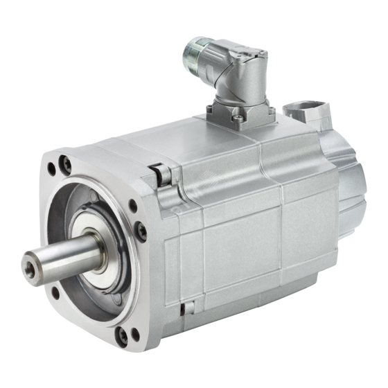
Description of the motors Highlights and benefits Overview 1FT7 synchronous motors are permanent-magnet motors with very compact dimensions. The motors can be quickly and easily mounted due to the well-proven cross-profile for shaft heights 36 to 100. The 1FT7 motors meet the highest demands for dynamic response and speed setting range, including field weakening, radial eccentricity, and positioning accuracy. - Page 24 Description of the motors 2.1 Highlights and benefits Benefits ● High degree of protection – allows operation even in difficult ambient conditions ● High ruggedness against vibration and shock loads as the encoder is mounted with effective vibration damping ● Quick and easy mounting due to cross-profile (for shaft heights 36 to 100) and rotatable connectors with quick-release locks ●...
-
Page 25: Intended Use
If you wish to use special versions and design variants whose specifications vary from the motors described in this document, then contact your local Siemens office. If you have any questions regarding the intended usage, please contact your local Siemens office. -
Page 26: Technical Features And Environmental Conditions
Description of the motors 2.3 Technical features and environmental conditions Technical features and environmental conditions 2.3.1 Standards and guidelines Standards that are complied with The motors of the type series SIMOTICS S, SIMOTICS M, SIMOTICS L, SIMOTICS T, SIMOTICS A, called "SIMOTICS motor series" below, fulfill the requirements of the following directives and standards: ●... - Page 27 Quality systems Siemens AG employs a quality management system that meets the requirements of ISO 9001 and ISO 14001. Certificates for SIMOTICS motors can be downloaded from the Internet at the following link: Certificates for SIMOTICS motors (https://support.industry.siemens.com/cs/products?dtp=Certificate&pnid=13347&lc=de-WW //...
-
Page 28: Technical Features
Description of the motors 2.3 Technical features and environmental conditions 2.3.2 Technical features Table 2- 1 Technical features Motor type Permanent-magnet synchronous motor Magnet material Rare-earth magnetic material Cooling Natural cooling • Forced ventilation • Water cooling • Insulation of the stator winding according to EN Temperature class 155 °C (F) for a winding overtemperature of 60034–1 ΔT = 100 K at an ambient temperature of +40 °C (naturally cooled,... - Page 29 Description of the motors 2.3 Technical features and environmental conditions Integrated encoder system for motors IC2048S/R incremental encoder sin/cos 1 Vpp, 2048 S/R • without DRIVE-CLiQ interface with C and D tracks AM2048S/R absolute encoder sin/cos 1 Vpp, 4096 revolu- •...
-
Page 30: Torque Overview
Description of the motors 2.3 Technical features and environmental conditions 2.3.3 Torque overview 1FT7 Compact Static torques for the 1FT7 Compact, natural cooling Static torques for the 1FT7 Compact, forced ventilation S-1FT7 synchronous motors Configuration Manual, 09/2018, A5E45099423B AA... - Page 31 Description of the motors 2.3 Technical features and environmental conditions Static torques for the 1FT7 Compact, water cooling 1FT7 High Dynamic Static torques for the 1FT7 High Dynamic, natural cooling Figure 2-2 Static torque High Dyn natural cooling Static torques for the 1FT7 High Dynamic, forced ventilation S-1FT7 synchronous motors Configuration Manual, 09/2018, A5E45099423B AA...
-
Page 32: Environmental Conditions
With the exception of environmental influences "Low air temperature", "Condensation" and "Low air pressure", you can assign SIMOTICS S-1FT7 servomotors to climate class 3K4. The following temperature ranges apply for naturally-cooled and forced-ventilation motors. - Page 33 Description of the motors 2.3 Technical features and environmental conditions Environmental parameter Unit Value Water (other than rain) See degree of protection Formation of ice Averaged over a period of 5 min Conditions in mines are not considered. A cooling system based on natural convection can be disturbed by unforeseen air movements. The limit value of 89 kPa covers applications at altitudes up to 1000 m.
-
Page 34: Derating Factors
Description of the motors 2.4 Derating factors Derating factors For deviating conditions (ambient temperature > 40 °C or installation altitude > 1000 m above sea level), you can determine the thermally permissible torques and powers from the table below. Ambient temperatures and installation altitudes are rounded up to 5°C and 500 m respectively. -
Page 35: Selection Based On The Article Number
(https://support.industry.siemens.com/cs/document/109747019/). Note that not every theoretical combination is available. Description Position of the article number 10 11 12 - 13 14 15 16 - SIMOTICS S-1FT7 synchronous built-in motors Frame size / shaft height SH 36 SH 48 SH 63... - Page 36 Description of the motors 2.5 Selection based on the article number Description Position of the article number 10 11 12 - 13 14 15 16 - Connector outlet direction Connector size Rotatable connector M23 and M40 Connector size Transverse right Transverse left Axial NDE Axial DE...
- Page 37 More detailed information is provided in Chapter "Special options (Page 80)" and in the associated Chapter "SIMOTICS Servomotors" in Catalog D 21.4 (https://support.industry.siemens.com/cs/document/109747019/) Only for 1FT7117 motors Additional colors can be found in Chapter "Special options (Page 80)" and in the as- sociated Chapter "SIMOTICS Servomotors"...
-
Page 38: Rating Plate Data (Type Plate)
Description of the motors 2.6 Rating plate data (type plate) Rating plate data (type plate) The rating plate contains the technical specifications applicable to the motor. A second rating plate is provided loose with the motor when it is delivered. Figure 2-3 Rating plate 1FT7 Table 2- 5... -
Page 39: Mechanical Properties
Mechanical properties Cooling 3.1.1 Natural cooling On naturally cooled motors, the heat loss is dissipated through thermal conduction, radiation and natural convection. Some of the heat loss is dissipated through the mounting surface of the motor. With large motors, heat is dissipated via the base frame (steel plate). Note the specifications on thermally non-insulated mounting and on thermally insulated mounting. - Page 40 Mechanical properties 3.1 Cooling Thermally insulated mounting without additionally mounted components For non-ventilated and force-ventilated motors, the static motor torque must be reduced by between 5% and 15%. We recommend configuring the static torque of the motor using the values. As the speed increases, the reduction factor rises, see figure "Effect of the 0 (60 K) mounting conditions on the S1 characteristic curve".
-
Page 41: Forced Ventilation
Mechanical properties 3.1 Cooling 3.1.2 Forced ventilation This cooling method is achieved using a separate ventilation unit with a fan that is driven independently of the motor. This fan has degree of protection IP54. WARNING Risk of explosion when operated in hazardous environments Operating the fan in an environment with inflammable, chemically corrosive, electrically conductive, or explosive dust or gases can cause explosions and result in death or serious injury. -
Page 42: Water Cooling
Mechanical properties 3.1 Cooling A minimum clearance of 30 mm applies for SH 63 and SH 80. A minimum clearance of 50 mm applies for SH 100. A minimum clearance of 60 mm applies for SH 132 Figure 3-2 Minimum clearance s 3.1.3 Water cooling The cooling circuit has to dissipate the following cooling powers. -
Page 43: Cooling Circuit
Mechanical properties 3.1 Cooling Motor type Cooling power to be dissipated in kW 1FT7102-5WF7 1400 1FT7105-5WB7 1200 1FT7105-5WC7 1600 1FT7105-5WF7 1900 1FT7108-5WB7 1500 1FT7108-5WC7 1800 1FT7108-5WF7 1900 Table 3- 4 Cooling power to be dissipated 1FT7 High Dynamic Motor type Cooling power to be dissipated in kW 1FT7065-7WF7 1FT7065-7WH7... - Page 44 Mechanical properties 3.1 Cooling Materials and components in the cooling circuit Note Minimizing electrochemical processes in the cooling circuit The electrochemical processes that take place in a cooling system must be minimized by choosing the right materials. Avoid combinations of different materials, such as copper, brass, iron, or halogenated plastic (PVC hoses and seals).
- Page 45 Mechanical properties 3.1 Cooling The following recommendation applies in order to achieve an optimum motor heatsink (enclosure) service life: ● Use a closed cooling circuit with stainless steel cooling unit. The heat is dissipated via a water-water heat exchanger. ● Use ABS, stainless steel, or general construction steel for all other components, such as pipes and fittings.
-
Page 46: Pressure Conditions In The Cooling Circuit
Mechanical properties 3.1 Cooling 3.1.3.2 Pressure conditions in the cooling circuit Consider the following pressure conditions when designing the cooling circuit. Permissible pressure ● Define the working pressure based on the flow conditions in the supply and return pipes of the cooling circuit. The maximum permitted pressure in the cooling circuit is 0.6 MPa (6 bar). - Page 47 Mechanical properties 3.1 Cooling Table 3- 7 Pressure drop at the nominal coolant flow Shaft height Flow rate Pressure drop 1FT706x 3 l/min 0.03 MPa 1FT708x 4 l/min 0.03 MPa 1FT710x 5 l/min 0.025 MPa Ensure the nominal coolant flows in the above table for sufficient heat dissipation. Pressure adjustment If various components are connected up in the cooling circuit, it may be necessary to measure the inlet and outlet pressure and adjust accordingly.
-
Page 48: Specification Of The Cooling Water
Mechanical properties 3.1 Cooling Connecting motors in series We can only recommend series connection of motors if: ● The required flow rates of the motors are approximately the same (< factor of 2) ● The maximum cooling water inlet temperature is maintained in the second or third motor. Note Derating of series-connected motors The heat dissipation of the cooling water in the second and third motor may require derating... - Page 49 Kinematic viscosity Flow rate / l/min The required derating can be obtained from Technical support. Please send your enquiry to Technical support (https://support.industry.siemens.com). Biocide The risk of corrosion caused by microbes is virtually non-existent in chlorinated drinking water systems. Closed cooling circuits with soft water are susceptible to microbes.
-
Page 50: Coolant Connection
Mechanical properties 3.1 Cooling Manufacturers of chemical additives Tyforop Chemie GmbH http://www.tyfo.de Clariant Produkte Deutschland GmbH (Anti- https://www.clariant.com frogen) Cimcool Industrial Products Inc http://www.cimcool.net FUCHS PETROLUB SE http://www.fuchs.com Hebro Chemie GmbH http://www.hebro-chemie.de HOUGHTON Deutschland GmbH http://www.houghton.com Nalco Water in Germany http://www.nalco.com (Ecolab) Schweitzer-Chemie GmbH... - Page 51 Mechanical properties 3.1 Cooling Equipotential bonding Provide all components in the cooling system (motor, heat exchanger, piping system, pump, pressure equalization tank, etc.) with equipotential bonding. Implement the equipotential bonding using a copper rail or finely stranded copper cable with the appropriate conductor cross-sections.
-
Page 52: Degree Of Protection
Mechanical properties 3.2 Degree of protection Degree of protection The degree of protection designation in accordance with EN 60034-5 (IEC 60034-5) is described using the letters IP and two digits, e.g. IP64. IP = International Protection 1st digit = protection against the ingress of foreign bodies 2nd digit = protection against water The validity of DIN 60034-5 refers to water as a medium that can potentially enter, and not oil. - Page 53 Mechanical properties 3.2 Degree of protection The motor shafts are sealed according to the degree of protection that is ordered. Table 3- 10 Sealing of the motor shaft IP64 IP65 IP67 Labyrinth seal Radial shaft sealing ring without annular Radial shaft sealing ring spring It is not permissible that there is For gearbox mounting (for gearboxes that...
-
Page 54: Types Of Construction
Mechanical properties 3.3 Types of construction Additional measures to increase tightness when using creep-capable oils ● DRIVE-CLiQ encoder with round connector M17, additional information in Chapter "Motors with DRIVE-CLiQ interface (Page 389)". ● Z option Q13: Encoder sealing (Page 102) ●... -
Page 55: Flange Forms
Mechanical properties 3.5 Flange forms Flange forms Table 3- 12 Flange forms Designation Representation Description Flange "compact" Flange recessed In the article number: 1FT7☐☐☐-☐☐☐☐0-☐☐☐☐ or 1FT7☐☐☐-☐☐☐☐5-☐☐☐☐ Flange "classic" Flange compatible with 1FT6/1FK7 motors In the article number: 1FT7☐☐☐-☐☐☐☐1-☐☐☐☐ or 1FT7☐☐☐-☐☐☐☐4-☐☐☐☐ S-1FT7 synchronous motors Configuration Manual, 09/2018, A5E45099423B AA... -
Page 56: Shaft Extension
Mechanical properties 3.6 Shaft extension Shaft extension The shaft extension at the DE is cylindrical according to DIN 748 Part 3, IEC 60072-1. Standard: Plain shaft (without keyway) Option: Keyway and feather key (half key balancing) For fast acceleration levels and reversing operation, we recommend that you use friction- locked shaft-hub coupling. -
Page 57: Radial Force Loading
Mechanical properties 3.7 Radial and axial forces Formula abbrevia- Unit Description tions ––– Pre-tensioning factor; this factor is an empirical value provided by the belt manufacturer. It can be assumed as follows: for toothed belts: c = 1.5 to 2.2 for flat belts c = 2.2 to 3.0 Effective diameter of the belt pulley Permissible radial force... -
Page 58: Radial Force Diagrams
Mechanical properties 3.7 Radial and axial forces 3.7.3 Radial force diagrams Radial force 1FT703☐ Permissible radial force on the shaft Figure 3-6 Radial force F at a distance x from the shaft shoulder for a statistical bearing lifetime of 25000 hours S-1FT7 synchronous motors Configuration Manual, 09/2018, A5E45099423B AA... - Page 59 Mechanical properties 3.7 Radial and axial forces Radial force 1FT704☐ Permissible radial force on the shaft Figure 3-7 Radial force F at a distance x from the shaft shoulder for a statistical bearing lifetime of 25000 hours Radial force, 1FT706☐ Figure 3-8 Radial force F at a distance x from the shaft shoulder for a statistical bearing lifetime of...
- Page 60 Mechanical properties 3.7 Radial and axial forces Radial force 1FT708☐ Figure 3-9 Radial force F at a distance x from the shaft shoulder for a statistical bearing lifetime of 25000 hours Radial force 1FT710☐ Figure 3-10 Radial force F at a distance x from the shaft shoulder for a statistical bearing lifetime of 25000 hours S-1FT7 synchronous motors Configuration Manual, 09/2018, A5E45099423B AA...
- Page 61 Mechanical properties 3.7 Radial and axial forces Radial force 1FT7, only SH117 Figure 3-11 Radial force F at a distance x from the shaft shoulder for a statistical bearing lifetime of 25000 hours Radial force 1FT713☐ Figure 3-12 Radial force F at a distance x from the shaft shoulder for a statistical bearing lifetime of 25000 hours S-1FT7 synchronous motors...
-
Page 62: Axial Force Loading
Mechanical properties 3.7 Radial and axial forces 3.7.4 Axial force loading When using, for example, helical toothed wheels as drive element, in addition to the radial force, there is also an axial force on the motor bearings. The axial forces can overcome the spring loading of the bearings so that the rotor is shifted corresponding to the bearing axial play that exists. -
Page 63: Radial Eccentricity, Concentricity And Axial Eccentricity
Mechanical properties 3.8 Radial eccentricity, concentricity and axial eccentricity Radial eccentricity, concentricity and axial eccentricity The shaft and flange accuracies are checked according to DIN 42955, IEC 60072-1. Any specifications deviating from these values are stated on the dimension drawings. Table 3- 15 Radial eccentricity tolerance of the shaft to the frame axis (referred to cylindrical shaft extensions) -
Page 64: Balancing
Mechanical properties 3.9 Balancing ① Checking the concentricity Motor ② Checking the axial eccentricity Motor shaft ③ Dial gauge Figure 3-14 Checking the concentricity and axial eccentricity Balancing The motors are balanced according to DIN ISO 8821. Motors with featherkey in the shaft are half-key balanced. A mass equalization for the protruding half key must be taken into account for the output elements. - Page 65 Mechanical properties 3.10 Vibration response Figure 3-15 Vibration severity grades Vibration response To ensure proper functioning and to comply with the motor specification (in particular the bearing lifetime), observe the vibration values specified in the following table. Table 3- 17 Vibration values Vibration velocity V to ISO 10816...
-
Page 66: Noise Emission
Mechanical properties 3.11 Noise emission 3.11 Noise emission When operated in the speed range 0 to rated speed, 1FT7 motors can reach the following measuring-surface sound pressure level Lp(A): Table 3- 18 Sound pressure level Cooling method Shaft height Measuring-surface sound pressure level Lp(A) Naturally cooled 1FT703 to 1FT706... -
Page 67: Service And Inspection Intervals
Service and maintenance must only be performed by properly authorized qualified personnel. Only use original SIEMENS parts. Siemens Service Centers distributed around the globe can maintain and repair the motor. To do this, contact your local Siemens representative. ● Perform the following maintenance measures as listed in the table. - Page 68 Mechanical properties 3.13 Service and inspection intervals S-1FT7 synchronous motors Configuration Manual, 09/2018, A5E45099423B AA...
-
Page 69: Motor Components And Options
Motor components and options Motor components 4.1.1 Thermal motor protection A temperature-dependent resistor is integrated as temperature sensor to monitor the motor temperature. ● 1FT7 motors with integrated DRIVE-CLiQ interface were switched over to Pt1000. The marking is made with the revision number of the motors. The order number does not need to be changed. - Page 70 Motor components and options 4.1 Motor components Table 4- 1 Features and technical specifications Type Pt1000 Not an ESD component Resistance when cold (20 °C) Approx. 1090 Ω Resistance when hot (100 °C) Approx. 1390 Ω Connection Via signal cable Response temperature Prewarning <...
-
Page 71: Encoders
Motor components and options 4.1 Motor components The temperature sensor is part of an SELV circuit, which can be destroyed if a high voltage is applied. The temperature sensor is designed so that the DIN/EN requirement for "protective separation" is fulfilled. Due to the thermal coupling time of the temperature sensor, high short-term overloads require additional protective measures. - Page 72 Motor components and options 4.1 Motor components Encoders with DRIVE-CLiQ interface: For SINAMICS drive systems Resolution 4,194,304 = 22 bit 4,194,304 = 22 bit Absolute position Yes, 4096 revolutions (12 bits) Max. angular error ± 40" ± 40" Encoder without DRIVE-CLiQ interface: EnDat 2.1 or Sin/Cos 1Vpp Incremental encoder Multiturn absolute encoders...
-
Page 73: Technical Specifications Of The Incremental Encoders
Motor components and options 4.1 Motor components 4.1.2.2 Technical specifications of the incremental encoders Description This encoder senses relative movements and does not supply absolute position information. In combination with evaluation logic, a zero point can be determined via the integrated reference mark, which can be used in turn to calculate the absolute position. -
Page 74: Technical Specifications Of The Absolute Encoders
Motor components and options 4.1 Motor components Incremental signals A/B track Zero pulse/reference signal Incremental signals C/D track Zero pulse/reference signal Figure 4-2 Signal sequence and assignment for encoder IC2048S/R without a DRIVE-CLiQ interface, for a positive direction of rotation For encoder connection, pin assignment, and cables, refer to Chapter "Connection system". - Page 75 Motor components and options 4.1 Motor components Function and technical specifications ● Angular measuring system for the commutation ● Speed actual value acquisition ● For singleturn encoder: Indirect measuring system for absolute position determination within a revolution ● For multiturn encoder: Indirect measuring system for determining the absolute position within a traversing range of 4096 revolutions Table 4- 3 Technical specifications, absolute encoder without DRIVE-CLiQ interface...
-
Page 76: Options
Motor components and options 4.2 Options Options 4.2.1 Holding brake 4.2.1.1 Type of the holding brake The holding brake is implemented as a permanent-magnet brake. The magnetic field of the permanent magnets exerts a pulling force on the brake armature disk. - Page 77 Motor components and options 4.2 Options / kgm Load moment of inertia of the mounted part at the motor with brake is as- Load sumed 3 x motor rotor moment of inertia with brake (kgm ) → see Chapter "Data sheets and characteristics (Page 150)" 182.4 Constant to calculate the angular frequency and SI units Example for calculating the highest braking energy for braking the 1FT7062-5AF7□-□□□□...
-
Page 78: Technical Specifications
Motor components and options 4.2 Options 4.2.1.3 Technical specifications Table 4- 5 Technical specifications of the holding brakes Motor type Holding torque Dyn. Braking DC current at Opening time Closing time Highest braking at 120 °C torque 20 °C energy with varistor with varistor / Nm... -
Page 79: Output Coupling
Motor components and options 4.2 Options Holding torque M The holding torque M is the highest possible torque that can be applied to the closed brake in steady-state operation without slip (holding function in a no-current state). Dynamic braking torque M The dynamic braking torque M is the smallest mean dynamic braking torque that can occur for an Emergency Stop. -
Page 80: Motors With Planetary Gearboxes
Selection and ordering data for the planetary gearboxes The selection and ordering data for the gearboxes is provided in Chapter "SIMOTICS Servomotors" in Catalog D 21.4 (https://support.industry.siemens.com/cs/document/109747019/) in the print version - or online. Note When selecting the motor-gearbox combination, ensure that the maximum permissible gearbox input speed is not exceeded. - Page 81 Motor components and options 4.2 Options The motor-gearbox combinations listed in the selection tables are predominantly for cyclic duty S3-60 % (ON duration ≤ 60 % and ≤ 20 min) . For use in continuous duty S1 (ON duration> 60 % or> 20 min) reduced maximum motor speeds and output torques apply.
-
Page 82: Special Options
Motor components and options 4.2 Options 4.2.4 Special options 4.2.4.1 Introduction The following options are available for the 1FT7. ● Option B02 - factory certificate ● Option J☐☐ - planetary gearbox mounting ● Option K20 - Reinforced bearing ● Option L03 - increased vibration stress ●... - Page 83 Motor components and options 4.2 Options Note If more than 2 options are ordered, no options will appear on line 2. In this case, specify the motor ID (No.YF) when ordering more motors of the same type. The following options can also be ordered. They are a part of the article number. ●...
-
Page 84: Option B02 - Manufacturer's Test Certificate
Motor components and options 4.2 Options 4.2.4.2 Option B02 - Manufacturer’s test certificate Option B02 provides a manufacturer’s test certificate according to DIN 55 350 Part 18 for motors according to DIN EN 10204:2004 (DIN 50049). You will find the 1FT7 motors that are available with option B02 in Section "Limited validity." The manufacturer’s test certificate states and certifies the values of the motor for ●... -
Page 85: Option K20 - Reinforced Bearing
Motor components and options 4.2 Options 4.2.4.3 Option K20 - Reinforced bearing The 1FT7 motors are available with reinforced bearings by selecting option K20. You will find the 1FT7 motors that are available with option K20 in Section "Limited validity." The following diagrams show the maximum permissible radial forces of the corresponding motor sizes for option K20. - Page 86 Motor components and options 4.2 Options Motor 1FT7064 Figure 4-8 Radial force diagram 1FT7064 Motor 1FT7066 Figure 4-9 Radial force diagram 1FT7066 S-1FT7 synchronous motors Configuration Manual, 09/2018, A5E45099423B AA...
- Page 87 Motor components and options 4.2 Options Motor 1FT7068 Figure 4-10 Radial force diagram 1FT7068 Motor 1FT7082 Figure 4-11 Radial force diagram 1FT7082 S-1FT7 synchronous motors Configuration Manual, 09/2018, A5E45099423B AA...
- Page 88 Motor components and options 4.2 Options Motor 1FT7084 Figure 4-12 Radial force diagram 1FT7084 Motor 1FT7086 Figure 4-13 Radial force diagram 1FT7086 S-1FT7 synchronous motors Configuration Manual, 09/2018, A5E45099423B AA...
- Page 89 Motor components and options 4.2 Options Motor 1FT7102 Figure 4-14 Radial force diagram 1FT7102 Motor 1FT7105 Figure 4-15 Radial force diagram 1FT7105 S-1FT7 synchronous motors Configuration Manual, 09/2018, A5E45099423B AA...
- Page 90 Motor components and options 4.2 Options Motor 1FT7108 Figure 4-16 Radial force diagram 1FT7108 Limited validity for 1FT7 motors Option K20 is only available for the standard type. The motors of the core type are not supplied with option K20. Motors with option K20 are only delivered with flange form "Classic".
-
Page 91: Option L03 - Increased Resistance To Vibration
Motor components and options 4.2 Options 4.2.4.4 Option L03 - Increased resistance to vibration The 1FT7 motors are available with the option L03 "Increased resistance to vibration". Area of application Applications of motors with option L03 include: ● Servo presses ●... - Page 92 Motor components and options 4.2 Options Limited validity Option L03 can be ordered for the above motors in the following version: ● 1FT7 Compact only ● with natural cooling or water cooling ● encoder types used – with DRIVE-CLiQ AS24DQI and AM24DQI –...
-
Page 93: Option L06 - Increased Shock Loads
Radial acceleration of 250 m/s² during a period of 10 shocks radial. Noise emission Measuring-surface sound pressure level p(A) < 80 dB (A) (speed range from 0 to rated speed) See also Sales and delivery release SIMOTICS S-1FT7117 (https://support.industry.siemens.com/cs/document/109742370/release-for-sales-and- delivery-simotics-s-1ft7117-(shaft-height-100-high-dynamic)?dti=0&lc=en-WW) S-1FT7 synchronous motors Configuration Manual, 09/2018, A5E45099423B AA... -
Page 94: Option N05 - Alternative Shaft Geometry
Motor components and options 4.2 Options 4.2.4.6 Option N05 - Alternative shaft geometry The 1FT7 motors are available with alternative shaft geometry by selecting option N05. You will find the 1FT7 motors that are available with option N05 in Section "Limited validity." The 1FT7 motors with option N05 ensure interchangeability with motors of the 1FT5 type series. - Page 95 ∅ 130 1FT710... 1FT510... ∅ 215 ∅ 180 You can find additional information in the "DT Configurator (http://siemens.de/dt- konfigurator)". Configuring The cantilever force diagrams provided in the Configuration Manual are also valid for 1FT7 servomotors with option N05. S-1FT7 synchronous motors...
-
Page 96: Option N16 - Increased Chemical Resistance
The 1FT7 motors are available with the option N16, protective properties for increased resistance to chemicals. You will find the 1FT7 motors that are available with option N16 in Product notification SIMOTICS S with option N16 (https://support.industry.siemens.com/cs/document/58657336). Additional characteristics of the motor with option N16 ● 4-coat paintwork ● Nickel-plated connectors ●... - Page 97 ● Connection requires a signal cable that deviates from the standard. Additional information is provided at Product notification SIMOTICS S with option N16 (https://support.industry.siemens.com/cs/document/58657336). Additional information on DRIVE-CLiQ signal cables with round connector M17 at the motor end is available at DRIVE-CLiQ cables for motors equipped with option N16 (https://support.industry.siemens.com/cs/document/109478937).
-
Page 98: Option N27 - Brake With Low Moment Of Inertia
Motor components and options 4.2 Options 4.2.4.8 Option N27 - Brake with low moment of inertia The option "Brake with low moment of inertia" is available for all 1FT7 motors except 1FT713☐. The brake has a lower moment of inertia than the standard brake. For the brake with low moment of inertia, the description and characteristics of the holding brake according to chapter "Holding brake (Page 74)"... -
Page 99: Option N40 - Increased Resistance To Industrial Cleaning
● Acidic and alkali cleaning agents with the pH value range 1.5. to 13. Note The resistance of the paint system "PS Premium" was verified in a material resistance test by ECOLAB Deutschland GmbH. See Product notification SIMOTICS S with option N40 (https://support.industry.siemens.com/cs/ww/de/view/85195226) S-1FT7 synchronous motors Configuration Manual, 09/2018, A5E45099423B AA... - Page 100 N16 (https://support.industry.siemens.com/cs/document/109478937). Further information on option N40 can be found at Product notification SIMOTICS S with option N40 (https://support.industry.siemens.com/cs/ww/de/view/85195226) Cleaning recommendation Cleaning recommendations for motors equipped with option N40 are provided in Product notification SIMOTICS S with option N40 (https://support.industry.siemens.com/cs/ww/de/view/85195226).
- Page 101 Motor components and options 4.2 Options Option N40 is only available for the following naturally cooled 1FT7 motors up to shaft height 100. ● 1FT703-5A☐711C☐2 - Z N40 / 1FT703☐5A☐711C☐5 - Z N40 ● 1FT704-5A☐711C☐2 - Z N40 / 1FT704☐5A☐711C☐5 - Z N40 ●...
-
Page 102: Option Q12 - Sealing Air Connection
Motor components and options 4.2 Options 4.2.4.10 Option Q12 - Sealing air connection The 1FT7 motors can be protected from the ingress of very creep-capable media with sealing air. The sealing air connection is ordered with option Q12. You will find the 1FT7 motors that are available with option Q12 in Section "Limited validity." Note Option Q12 can only be ordered in conjunction with degree of protection IP67. - Page 103 Motor components and options 4.2 Options Requirements of the sealing air supply Conditioning the sealing air Minimum supply air temperature in °C Ambient temperature Maximum supply air temperature in °C Maximum residual water content in g/m³ 0.12 Maximum residual oil content in g/m³ 0.01 Maximum residual dust in mg/m³...
-
Page 104: Option Q13 - Encoder Sealing
Motor components and options 4.2 Options 4.2.4.11 Option Q13 - Encoder sealing Z option Q13 improves sealing at the flange sealing surfaces of the encoder and power connector on the motor with wetting sealant adhesive. Encoder replacement is only possible in a specialist workshop or at the manufacturer's. Option Q13 is only available for motors with DQI encoders that have the following letters at the 14th position of the article number: Article number... -
Page 105: Options X.., K23, K24, And N16 - Paint Finish
Motor components and options 4.2 Options 4.2.4.13 Options X.., K23, K24, and N16 - Paint finish Paint finish If no special color is selected, 1FT7 type series motors are painted in the standard color pearl dark gray (RAL 9023). Figure 4-19 1FT7 standard color The 1FT7 servomotor can be supplied in various colors. - Page 106 Motor components and options 4.2 Options Special colors (option X..) Designation Order code Color schemes RAL 6019, pastel green RAL 5010, gentian blue RAL 5024, pastel blue RAL 5017, traffic blue RAL 9010, pure white RAL 6018, yellow green RAL 5014, pigeon blue RAL 9018, papyrus white RAL 2004, pure orange RAL 9003, signal white...
- Page 107 Motor components and options 4.2 Options Designation Order code Color schemes RAL 2001, red orange RAL 7030, stone gray Primer (option K23, K24) 1FT7 motors can be supplied with primer finish. The following versions are possible. Description Order code Color schemes Primed in RAL 6021, pale green, without additional coat of paint Special paint finish corresponding to the environmental...
-
Page 108: Option Y84 - Customer Data On The Rating Plate
Motor components and options 4.2 Options 4.2.4.14 Option Y84 - Customer data on the rating plate Option Y84 permits customer data on the rating plate of the motor. If you are ordering electronically, you can enter the text for the rating plate when you select option Y84. Note The text can be up to 20 characters long. -
Page 109: Configuration
● Comments on system reactions ● Installation information of the drive and control components ● Energy considerations of the configured drive systems You can find additional information that you can download in the Internet at SIZER (https://support.industry.siemens.com/cs/document/54992004/sizer-for-siemens- drives?dti=0&pnid=13434&lc=en-WW). 5.1.2 STARTER drive/commissioning software The STARTER commissioning tool offers ●... -
Page 110: Procedure When Engineering
Configuration 5.2 Procedure when engineering Procedure when engineering Motion control Drives are optimized for motion control applications. They execute linear or rotary movements within a defined movement cycle. All movements should be optimized in terms of time. As a result, drives must meet the following requirements: ●... -
Page 111: Clarification Of The Drive Type
Configuration 5.2 Procedure when engineering 5.2.1 1. Clarification of the drive type Select the motor on the basis of the required torque (load torque), which is defined by the application, e.g. traveling drives, hoisting drives, test stands, centrifuges, paper and rolling mill drives, feed drives or main spindle drives. -
Page 112: Definition Of The Load, Calculation Of The Maximum Load Torque And Determination Of The Motor
Configuration 5.2 Procedure when engineering 5.2.3 3. Definition of the load, calculation of the maximum load torque and determination of the motor The motors are defined bases on the motor type-specific limiting characteristic curves. The limiting characteristic curves describe the torque or power curve over the speed. The limiting characteristic curves take the limits of the motor into account on the basis of the DC-link voltage. - Page 113 Configuration 5.2 Procedure when engineering 3. Calculate the acceleration torque of the motor. Add the load torque and the acceleration torque to obtain the maximum required torque. 4. Verify the maximum motor torque with the limiting characteristic curves of the motors. The following criteria must be taken into account when selecting the motor: –...
- Page 114 Configuration 5.2 Procedure when engineering Procedure 1. Configure a base load for the stationary operating point. The base load torque must lie below the S1 characteristic curve. 2. In the event of transient overloads (e.g. during acceleration), configure an overload. Calculate the overload current in relation to the required overload torque.
- Page 115 Configuration 5.2 Procedure when engineering Duty cycles with varying ON duration Standardized intermittent duties (S3) are specified for duty cycles with varying ON durations Each intermittent duty (S3) is made up of a sequence of duty cycles of the same type. Each duty cycle encompasses a time with constant load and a pause.
- Page 116 Configuration 5.2 Procedure when engineering Free duty cycle A free duty cycle defines the curve of the motor speed and the torque over time. Speed Cycle time Torque Δt Time interval Time Figure 5-5 Example of free duty cycle Procedure Determine the required motor torque as follows: ●...
- Page 117 Configuration 5.2 Procedure when engineering The following formulas can be used for duty cycles outside the field weakening range. For duty cycles in the field weakening range, the drive system must be configured using the SIZER configuration tool. For the motor torque in a time slice Δ the following applies: The motor speed is: The effective torque is obtained as follows:...
- Page 118 Configuration 5.2 Procedure when engineering M_max Curve of the maximum S1 (100K) S1 characteristic curve for 100 K = M torque (100K) M_eff Effective torque ● Points from the traversing profile n_mean Mean speed M_VLim Voltage limiting characteristic curve Figure 5-6 Motor selection for duty cycle (example) You have defined the characteristic motor values corresponding to the duty cycle.
-
Page 119: Dimensioning The Gearbox
Configuration 5.3 Dimensioning the gearbox Dimensioning the gearbox Overview ● Take into account the following influencing variables when configuring the gearbox: – Accelerating torque – Continuous torque – Number of cycles – Cycle type – Permissible input speed – Mounting position –... - Page 120 Configuration 5.3 Dimensioning the gearbox NOTICE Gearbox failures as a result of superimposed oscillations Switching cycles can also be superimposed oscillations. The safety factor (f ) is then not adequately dimensioned. This can result in gearbox failures. • Optimize the overall system so that the superimposed oscillations are minimized. Motor Gearbox Figure 5-7...
- Page 121 Configuration 5.3 Dimensioning the gearbox Change in characteristic due to mounted gearbox Figure 5-8 S1 characteristic (example) = S1 - (S1 - S1 Note relating to additional characteristics: gearbox 100 K 100 K 60 K Starting response of a motor with mounted gearbox Note When commissioning, increased currents can be drawn as a result of the lubricating characteristics (inadequate distribution of oil or grease) - and the running-in behavior of the...
-
Page 122: Brake Resistances (Armature Short-Circuit Braking)
Configuration 5.4 Brake resistances (armature short-circuit braking) Brake resistances (armature short-circuit braking) 5.4.1 Description of function braking resistor The motor cannot be electrically braked if, for converters ● The permissible DC link voltage values are exceeded ● The electronics fails Then, the motor that is coasting down can only be braked using an armature short circuit. - Page 123 Configuration 5.4 Brake resistances (armature short-circuit braking) Figure 5-9 Circuit (schematic) with brake resistors Rating NOTICE Destruction of the braking resistors Braking from the rated speed is not permitted any more frequently than every 2 minutes; otherwise the resistors will be destroyed. •...
- Page 124 Configuration 5.4 Brake resistances (armature short-circuit braking) Calculating the braking time The values for calculation are provided in Chapter "Data sheets and characteristics (Page 150)". • n Braking time / 9.55 • / s = braking time / rpm = operating speed / Nm = average braking torque Moment of iner- / kgm...
- Page 125 Configuration 5.4 Brake resistances (armature short-circuit braking) Armature short-circuit braking with external braking resistor without external braking resistor = braking torque = rms braking current Br rms = average braking torque = run-out time Br rms = optimum braking torque n = speed Br opt = braking current...
-
Page 126: Dimensioning Of Braking Resistors
Configuration 5.4 Brake resistances (armature short-circuit braking) 5.4.2 Dimensioning of braking resistors Correct dimensioning of the braking resistors determines the optimum braking time. The braking torques that are obtained are listed in the tables. The data applies for braking from the rated speed and moment of inertia J external If you brake the drive from another speed, the braking time cannot simply be reduced proportionally. - Page 127 Configuration 5.4 Brake resistances (armature short-circuit braking) Motor type External brak- Average braking torque Max. braking rms braking current I Br rms br rms ing resistor torque Br max / Ω Without external With external Without exter- With external braking resistor braking resis- nal braking braking resis-...
- Page 128 Configuration 5.4 Brake resistances (armature short-circuit braking) 1FT7 Compact, forced ventilation Table 5- 4 Armature short-circuit braking with/without external braking resistors Motor type External brak- Average braking torque Max. braking rms braking current I Br rms br rms ing resistor torque Br max / Ω...
- Page 129 Configuration 5.4 Brake resistances (armature short-circuit braking) 1FT7 Compact, liquid cooling Table 5- 5 Armature short-circuit braking with/without external braking resistors Motor type External brak- Average braking torque Max. braking rms braking current I Br rms br rms ing resistor torque Br max / Ω...
- Page 130 Configuration 5.4 Brake resistances (armature short-circuit braking) 1FT7 High Dynamic, natural cooling Table 5- 6 Armature short-circuit braking with/without external braking resistors Motor type External brak- Average braking torque Max. braking rms braking current I Br rms br rms ing resistor torque Br max / Ω...
- Page 131 Configuration 5.4 Brake resistances (armature short-circuit braking) 1FT7 High Dynamic, liquid cooling Table 5- 8 Armature short-circuit braking with/without external braking resistors Motor type External brak- Average braking torque Max. braking rms braking current I Br rms br rms ing resistor torque Br max / Ω...
- Page 132 Configuration 5.4 Brake resistances (armature short-circuit braking) S-1FT7 synchronous motors Configuration Manual, 09/2018, A5E45099423B AA...
-
Page 133: Technical Data And Characteristic Curves
Technical data and characteristic curves Explanations Permissible operating range The permissible operating range is limited by thermal, mechanical, and electromagnetic boundaries. The data in this documentation apply to the following temperatures: ● For naturally cooled motors: up to 40 °C ambient temperature ●... - Page 134 Technical data and characteristic curves 6.1 Explanations Permissible temperature range, characteristics S1 and S1 (100 K) (60 K) 1FT7 motors can be operated up to an average winding temperature of 145 °C. The S1 characteristic in the diagram "Torque characteristics of synchronous motors" (100 K) indicates the limits of the permissible temperature range for continuous operation.
- Page 135 Technical data and characteristic curves 6.1 Explanations Speed limits n and n max mech max conv The speed range is limited by the following variables: ● The mechanical speed limit n (rotor centrifugal forces, bearing lifetime) max mech ● The electrical speed limit n (voltage strength of the converter and/or max.
- Page 136 Technical data and characteristic curves 6.1 Explanations Voltage limit characteristic without field weakening Volt lim Voltage limit characteristic with field weakening Without field weakening Field weakening range Figure 6-2 Shape of the voltage limiting characteristic with/without field weakening The characteristics for each winding version are shown in a separate data sheet. The torque-speed diagrams for different converter output voltages are assigned to each data sheet: Table 6- 1...
- Page 137 Technical data and characteristic curves 6.1 Explanations The difference between the DC link voltage of the converter and the induced motor voltage can be used to impress the current. This difference limits the applicable current level. This causes the torque to drop off quickly at high speeds. All operating points that can be achieved with the motor lie to the left of the voltage limiting characteristic line in area "A".
- Page 138 Technical data and characteristic curves 6.1 Explanations ① Voltage limiting characteristic curve = torque limit without field weakening, e.g. with winding types C, F, H, K Figure 6-3 Speed-torque diagram Note The voltage limit characteristic of a motor with 6000 rpm rated speed is far above that of the same motor type with 2000 rpm.
- Page 139 Technical data and characteristic curves 6.1 Explanations Shifting the voltage limiting characteristic by a factor x If the converter output voltage (U ) is not equal to 380 V, 425 V, 460 V or 510 V, then you must shift the voltage limiting characteristic involved for the new output voltage (U Mot, new x = U = new converter output voltage / V...
- Page 140 Technical data and characteristic curves 6.1 Explanations 2. Determine P2, the new point of intersection of the voltage limiting characteristic on the x axis. P2 corresponds to n - calculate this as follows: • / rpm; Mot new Converter output voltage Mot new 3.
- Page 141 Technical data and characteristic curves 6.1 Explanations Calculating and determining points P1, P2, P3 and P4 = 380 V • 1000 / 87 • 0.95 = 4597 rpm = 4597 rpm • 290 V / 380 V = 3508 rpm = 3000 rpm and = 380 V read: = approx.
- Page 142 Technical data and characteristic curves 6.1 Explanations Tolerance data The data shown in the data sheets are nominal values that are subject to natural variation. The following tolerances apply: Table 6- 4 Tolerance data in the motor list data Motor list data Typ.
- Page 143 Technical data and characteristic curves 6.1 Explanations Figure 6-6 Effect of the parameter spread Note The motor temperature results in a clear displacement of the voltage limiting characteristic in the upper speed range. Consider this when configuring applications with converter systems without field weakening, in which the cold motor has to produce maximum speeds.
-
Page 144: Motor Overview / Assignment Of Motor Modules / Power Cables
1FT7 on the following pages. You can find additional information in the catalog "Chapter, "MOTION-CONNECT connection systems" in Catalog D 21.4 (https://intranet.for.siemens.com/org/i-dt-mc/de/motion- control/support/infomaterial/kataloge/d-21-4-sinamics-s120-simotics/Seiten/d-21-4.aspx)". 1FT7 for SINAMICS S120 Booksize, DC link voltages 510 V to 720 V DC, (line voltages, 380 V to... - Page 145 Technical data and characteristic curves 6.2 Motor overview / assignment of Motor Modules / power cables SINAMICS S120 Booksize, DC link voltages 510 V to 720 V DC, (line voltages, 3 AC 380 V to 480 V) You can find the matching SINAMICS Motor Modules and MOTION-CONNECT power cables in the following tables.
- Page 146 Technical data and characteristic curves 6.2 Motor overview / assignment of Motor Modules / power cables Table 6- 6 1FT7 Compact natural cooling Motor Converter: SINAMICS S120 Booksize Power cable Order number / Nm Connector size Order number Base load Order number max (100K) Inv 1) 0 (100K)
- Page 147 Technical data and characteristic curves 6.2 Motor overview / assignment of Motor Modules / power cables Motor Converter: SINAMICS S120 Booksize Power cable Order number / Nm Connector size Order number Base load Order number max (100K) Inv 1) 0 (100K) current Cable cross- section...
- Page 148 Technical data and characteristic curves 6.2 Motor overview / assignment of Motor Modules / power cables Table 6- 7 1FT7 Compact forced ventilation Motor Converter: SINAMICS S120 Booksize Power cable Order number / Nm Connector size Order number Base load Order number max (100K) Inv 1) 0 (100K)
- Page 149 Technical data and characteristic curves 6.2 Motor overview / assignment of Motor Modules / power cables Table 6- 8 1FT7 Compact water cooling Motor Converter: SINAMICS S120 Booksize Power cable Order number / Nm Connector size Order number Base load Order number max (100K) Inv 1) 0 (100K)
- Page 150 Technical data and characteristic curves 6.2 Motor overview / assignment of Motor Modules / power cables Motor Converter: SINAMICS S120 Booksize Power cable Order number / Nm Connector size Order number Base load Order number max (100K) Inv 1) 0 (100K) current Cable cross- section...
- Page 151 Technical data and characteristic curves 6.2 Motor overview / assignment of Motor Modules / power cables Table 6- 11 1FT7 High Dynamic water cooling Motor Converter: SINAMICS S120 Booksize Power cable Order number / Nm Connector size Order number Base load Order number max (100K) Inv 1) 0 (100K)
-
Page 152: Data Sheets And Characteristics
Technical data and characteristic curves 6.3 Data sheets and characteristics Data sheets and characteristics 6.3.1 1FT7 Compact - natural cooling 6.3.1.1 1FT7034-_A Three-phase servomotor 1FT7034-5AK7 Technical specifications Symbol Unit Value Configuration data: Rated speed 6000 Rated torque (100K) N(100K) Rated current (100K) N(100K) Static torque (100K) 0(100K) - Page 153 Technical data and characteristic curves 6.3 Data sheets and characteristics S-1FT7 synchronous motors Configuration Manual, 09/2018, A5E45099423B AA...
-
Page 154: 1Ft7036-_A
Technical data and characteristic curves 6.3 Data sheets and characteristics 6.3.1.2 1FT7036-_A Three-phase servomotor 1FT7036-5AK7 Technical specifications Symbol Unit Value Configuration data: Rated speed 6000 Rated torque (100K) N(100K) Rated current (100K) N(100K) Static torque (100K) 0(100K) Stall current (100K) 0(100K) Static torque (60K) 0(60K) - Page 155 Technical data and characteristic curves 6.3 Data sheets and characteristics S-1FT7 synchronous motors Configuration Manual, 09/2018, A5E45099423B AA...
-
Page 156: 1Ft7042-_A
Technical data and characteristic curves 6.3 Data sheets and characteristics 6.3.1.3 1FT7042-_A Three-phase servomotor 1FT7042-5AF7 Technical specifications Symbol Unit Value Configuration data: Rated speed 3000 Rated torque (100K) N(100K) Rated current (100K) N(100K) Static torque (100K) 0(100K) Stall current (100K) 0(100K) Static torque (60K) 0(60K) - Page 157 Technical data and characteristic curves 6.3 Data sheets and characteristics S-1FT7 synchronous motors Configuration Manual, 09/2018, A5E45099423B AA...
- Page 158 Technical data and characteristic curves 6.3 Data sheets and characteristics Three-phase servomotor 1FT7042-5AK7 Technical specifications Symbol Unit Value Configuration data: Rated speed 6000 Rated torque (100K) N(100K) Rated current (100K) N(100K) Static torque (100K) 0(100K) Stall current (100K) 0(100K) Static torque (60K) 0(60K) Stall current (60K) 0(60K)
- Page 159 Technical data and characteristic curves 6.3 Data sheets and characteristics S-1FT7 synchronous motors Configuration Manual, 09/2018, A5E45099423B AA...
-
Page 160: 1Ft7044-_A
Technical data and characteristic curves 6.3 Data sheets and characteristics 6.3.1.4 1FT7044-_A Three-phase servomotor 1FT7044-5AF7 Technical specifications Symbol Unit Value Configuration data: Rated speed 3000 Rated torque (100K) N(100K) Rated current (100K) N(100K) Static torque (100K) 0(100K) Stall current (100K) 0(100K) Static torque (60K) 0(60K) - Page 161 Technical data and characteristic curves 6.3 Data sheets and characteristics S-1FT7 synchronous motors Configuration Manual, 09/2018, A5E45099423B AA...
- Page 162 Technical data and characteristic curves 6.3 Data sheets and characteristics Three-phase servomotor 1FT7044-5AK7 Technical specifications Symbol Unit Value Configuration data: Rated speed 6000 Rated torque (100K) N(100K) Rated current (100K) N(100K) Static torque (100K) 0(100K) Stall current (100K) 0(100K) Static torque (60K) 0(60K) Stall current (60K) 0(60K)
- Page 163 Technical data and characteristic curves 6.3 Data sheets and characteristics S-1FT7 synchronous motors Configuration Manual, 09/2018, A5E45099423B AA...
-
Page 164: 1Ft7046-_A
Technical data and characteristic curves 6.3 Data sheets and characteristics 6.3.1.5 1FT7046-_A Three-phase servomotor 1FT7046-5AF7 Technical specifications Symbol Unit Value Configuration data: Rated speed 3000 Rated torque (100K) N(100K) Rated current (100K) N(100K) Static torque (100K) 0(100K) Stall current (100K) 0(100K) Static torque (60K) 0(60K) - Page 165 Technical data and characteristic curves 6.3 Data sheets and characteristics S-1FT7 synchronous motors Configuration Manual, 09/2018, A5E45099423B AA...
- Page 166 Technical data and characteristic curves 6.3 Data sheets and characteristics Three-phase servomotor 1FT7046-5AH7 Technical specifications Symbol Unit Value Configuration data: Rated speed 4500 Rated torque (100K) N(100K) Rated current (100K) N(100K) Static torque (100K) 0(100K) Stall current (100K) 0(100K) Static torque (60K) 0(60K) Stall current (60K) 0(60K)
- Page 167 Technical data and characteristic curves 6.3 Data sheets and characteristics S-1FT7 synchronous motors Configuration Manual, 09/2018, A5E45099423B AA...
-
Page 168: 1Ft7062-_A
Technical data and characteristic curves 6.3 Data sheets and characteristics 6.3.1.6 1FT7062-_A Three-phase servomotor 1FT7062-5AF7 Technical specifications Symbol Unit Value Configuration data: Rated speed 3000 Rated torque (100K) N(100K) Rated current (100K) N(100K) Static torque (100K) 0(100K) Stall current (100K) 0(100K) Static torque (60K) 0(60K) - Page 169 Technical data and characteristic curves 6.3 Data sheets and characteristics S-1FT7 synchronous motors Configuration Manual, 09/2018, A5E45099423B AA...
- Page 170 Technical data and characteristic curves 6.3 Data sheets and characteristics Three-phase servomotor 1FT7062-5AK7 Technical specifications Symbol Unit Value Configuration data: Rated speed 6000 Rated torque (100K) N(100K) Rated current (100K) N(100K) Static torque (100K) 0(100K) Stall current (100K) 0(100K) Static torque (60K) 0(60K) Stall current (60K) 0(60K)
- Page 171 Technical data and characteristic curves 6.3 Data sheets and characteristics S-1FT7 synchronous motors Configuration Manual, 09/2018, A5E45099423B AA...
-
Page 172: 1Ft7064-_A
Technical data and characteristic curves 6.3 Data sheets and characteristics 6.3.1.7 1FT7064-_A Three-phase servomotor 1FT7064-5AF7 Technical specifications Symbol Unit Value Configuration data: Rated speed 3000 Rated torque (100K) N(100K) Rated current (100K) N(100K) Static torque (100K) 0(100K) Stall current (100K) 0(100K) Static torque (60K) 0(60K) - Page 173 Technical data and characteristic curves 6.3 Data sheets and characteristics S-1FT7 synchronous motors Configuration Manual, 09/2018, A5E45099423B AA...
- Page 174 Technical data and characteristic curves 6.3 Data sheets and characteristics Three-phase servomotor 1FT7064-5AK7 Technical specifications Symbol Unit Value Configuration data: Rated speed 6000 Rated torque (100K) N(100K) Rated current (100K) N(100K) Static torque (100K) 0(100K) Stall current (100K) 0(100K) Static torque (60K) 0(60K) Stall current (60K) 0(60K)
- Page 175 Technical data and characteristic curves 6.3 Data sheets and characteristics S-1FT7 synchronous motors Configuration Manual, 09/2018, A5E45099423B AA...
-
Page 176: 1Ft7066-_A
Technical data and characteristic curves 6.3 Data sheets and characteristics 6.3.1.8 1FT7066-_A Three-phase servomotor 1FT7066-5AF7 Technical specifications Symbol Unit Value Configuration data: Rated speed 3000 Rated torque (100K) N(100K) Rated current (100K) N(100K) Static torque (100K) 12.0 0(100K) Stall current (100K) 0(100K) Static torque (60K) 10.0... - Page 177 Technical data and characteristic curves 6.3 Data sheets and characteristics S-1FT7 synchronous motors Configuration Manual, 09/2018, A5E45099423B AA...
- Page 178 Technical data and characteristic curves 6.3 Data sheets and characteristics Three-phase servomotor 1FT7066-5AH7 Technical specifications Symbol Unit Value Configuration data: Rated speed 4500 Rated torque (100K) N(100K) Rated current (100K) N(100K) Static torque (100K) 12.0 0(100K) Stall current (100K) 13.6 0(100K) Static torque (60K) 10.0...
- Page 179 Technical data and characteristic curves 6.3 Data sheets and characteristics S-1FT7 synchronous motors Configuration Manual, 09/2018, A5E45099423B AA...
-
Page 180: 1Ft7068-_A
Technical data and characteristic curves 6.3 Data sheets and characteristics 6.3.1.9 1FT7068-_A Three-phase servomotor 1FT7068-5AF7 Technical specifications Symbol Unit Value Configuration data: Rated speed 3000 Rated torque (100K) 10.9 N(100K) Rated current (100K) N(100K) Static torque (100K) 15.0 0(100K) Stall current (100K) 0(100K) Static torque (60K) 13.0... - Page 181 Technical data and characteristic curves 6.3 Data sheets and characteristics S-1FT7 synchronous motors Configuration Manual, 09/2018, A5E45099423B AA...
-
Page 182: 1Ft7082-_A
Technical data and characteristic curves 6.3 Data sheets and characteristics 6.3.1.10 1FT7082-_A Three-phase servomotor 1FT7082-5AC7 Technical specifications Symbol Unit Value Configuration data Rated speed 2000 Rated torque (100K) 11.4 N(100K) Rated current (100K) N(100K) Static torque (100K) 13.0 0(100K) Stall current (100K) 0(100K) Static torque (60K) 10.6... - Page 183 Technical data and characteristic curves 6.3 Data sheets and characteristics S-1FT7 synchronous motors Configuration Manual, 09/2018, A5E45099423B AA...
- Page 184 Technical data and characteristic curves 6.3 Data sheets and characteristics Three-phase servomotor 1FT7082-5AF7 Technical specifications Symbol Unit Value Configuration data: Rated speed 3000 Rated torque (100K) 10.3 N(100K) Rated current (100K) N(100K) Static torque (100K) 13.0 0(100K) Stall current (100K) 0(100K) Static torque (60K) 10.6...
- Page 185 Technical data and characteristic curves 6.3 Data sheets and characteristics S-1FT7 synchronous motors Configuration Manual, 09/2018, A5E45099423B AA...
- Page 186 Technical data and characteristic curves 6.3 Data sheets and characteristics Three-phase servomotor 1FT7082-5AH7 Technical specifications Symbol Unit Value Configuration data Rated speed 4500 Rated torque (100K) N(100K) Rated current (100K) N(100K) Static torque (100K) 13.0 0(100K) Stall current (100K) 12.3 0(100K) Static torque (60K) 10.6...
- Page 187 Technical data and characteristic curves 6.3 Data sheets and characteristics S-1FT7 synchronous motors Configuration Manual, 09/2018, A5E45099423B AA...
-
Page 188: 1Ft7084-_A
Technical data and characteristic curves 6.3 Data sheets and characteristics 6.3.1.11 1FT7084-_A Three-phase servomotor 1FT7084-5AC7 Technical specifications Symbol Unit Value Configuration data: Rated speed 2000 Rated torque (100K) 16.9 N(100K) Rated current (100K) N(100K) Static torque (100K) 20.0 0(100K) Stall current (100K) 0(100K) Static torque (60K) 16.8... - Page 189 Technical data and characteristic curves 6.3 Data sheets and characteristics S-1FT7 synchronous motors Configuration Manual, 09/2018, A5E45099423B AA...
- Page 190 Technical data and characteristic curves 6.3 Data sheets and characteristics Three-phase servomotor 1FT7084-5AF7 Technical specifications Symbol Unit Value Configuration data: Rated speed 3000 Rated torque (100K) 14.5 N(100K) Rated current (100K) N(100K) Static torque (100K) 20.0 0(100K) Stall current (100K) 0(100K) Static torque (60K) 16.8...
- Page 191 Technical data and characteristic curves 6.3 Data sheets and characteristics S-1FT7 synchronous motors Configuration Manual, 09/2018, A5E45099423B AA...
- Page 192 Technical data and characteristic curves 6.3 Data sheets and characteristics Three-phase servomotor 1FT7084-5AH7 Technical specifications Symbol Unit Value Configuration data: Rated speed 4500 Rated torque (100K) N(100K) Rated current (100K) N(100K) Static torque (100K) 0(100K) Stall current (100K) 15.6 0(100K) Static torque (60K) 16.8 0(60K)
- Page 193 Technical data and characteristic curves 6.3 Data sheets and characteristics S-1FT7 synchronous motors Configuration Manual, 09/2018, A5E45099423B AA...
-
Page 194: 1Ft7086-_A
Technical data and characteristic curves 6.3 Data sheets and characteristics 6.3.1.12 1FT7086-_A Three-phase servomotor 1FT7086-5AC7 Technical specifications Symbol Unit Value Configuration data: Rated speed 2000 Rated torque (100K) 22.5 N(100K) Rated current (100K) N(100K) Static torque (100K) 28.0 0(100K) Stall current (100K) 10.6 0(100K) Static torque (60K) - Page 195 Technical data and characteristic curves 6.3 Data sheets and characteristics S-1FT7 synchronous motors Configuration Manual, 09/2018, A5E45099423B AA...
- Page 196 Technical data and characteristic curves 6.3 Data sheets and characteristics Three-phase servomotor 1FT7086-5AF7 Technical specifications Symbol Unit Value Configuration data: Rated speed 3000 Rated torque (100K) 18.0 N(100K) Rated current (100K) 11.0 N(100K) Static torque (100K) 0(100K) Stall current (100K) 15.5 0(100K) Static torque (60K)
- Page 197 Technical data and characteristic curves 6.3 Data sheets and characteristics S-1FT7 synchronous motors Configuration Manual, 09/2018, A5E45099423B AA...
- Page 198 Technical data and characteristic curves 6.3 Data sheets and characteristics Three-phase servomotor 1FT7086-5AH7 Technical specifications Symbol Unit Value Configuration data: Rated speed 4500 Rated torque (100K) 10.0 N(100K) Rated current (100K) N(100K) Static torque (100K) 0(100K) Stall current (100K) 22.4 0(100K) Static torque (60K) 0(60K)
- Page 199 Technical data and characteristic curves 6.3 Data sheets and characteristics S-1FT7 synchronous motors Configuration Manual, 09/2018, A5E45099423B AA...
-
Page 200: 1Ft7102-_A
Technical data and characteristic curves 6.3 Data sheets and characteristics 6.3.1.13 1FT7102-_A Three-phase servomotor 1FT7102-5AB7 Technical specifications Symbol Unit Value Configuration data: Rated speed 1500 Rated torque (100K) 26.0 N(100K) Rated current (100K) N(100K) Static torque (100K) 30.0 0(100K) Stall current (100K) 0(100K) Static torque (60K) 25.0... - Page 201 Technical data and characteristic curves 6.3 Data sheets and characteristics S-1FT7 synchronous motors Configuration Manual, 09/2018, A5E45099423B AA...
- Page 202 Technical data and characteristic curves 6.3 Data sheets and characteristics Three-phase servomotor 1FT7102-5AC7 Technical specifications Symbol Unit Value Configuration data Rated speed 2000 Rated torque (100K) N(100K) Rated current (100K) N(100K) Static torque (100K) 0(100K) Stall current (100K) 12.5 0(100K) Static torque (60K) 0(60K) Stall current (60K)
- Page 203 Technical data and characteristic curves 6.3 Data sheets and characteristics S-1FT7 synchronous motors Configuration Manual, 09/2018, A5E45099423B AA...
- Page 204 Technical data and characteristic curves 6.3 Data sheets and characteristics Three-phase servomotor 1FT7102-5AF7 Technical specifications Symbol Unit Value Configuration data: Rated speed 3000 Rated torque (100K) 20.0 N(100K) Rated current (100K) 12.0 N(100K) Static torque (100K) 30.0 0(100K) Stall current (100K) 18.0 0(100K) Static torque (60K)
- Page 205 Technical data and characteristic curves 6.3 Data sheets and characteristics S-1FT7 synchronous motors Configuration Manual, 09/2018, A5E45099423B AA...
-
Page 206: 1Ft7105-_A
Technical data and characteristic curves 6.3 Data sheets and characteristics 6.3.1.14 1FT7105-_A Three-phase servomotor 1FT7105-5AB7 Technical specifications Symbol Unit Value Configuration data: Rated speed 1500 Rated torque (100K) 42.0 N(100K) Rated current (100K) 13.0 N(100K) Static torque (100K) 50.0 0(100K) Stall current (100K) 15.0 0(100K) - Page 207 Technical data and characteristic curves 6.3 Data sheets and characteristics S-1FT7 synchronous motors Configuration Manual, 09/2018, A5E45099423B AA...
- Page 208 Technical data and characteristic curves 6.3 Data sheets and characteristics Three-phase servomotor 1FT7105-5AC7 Technical specifications Symbol Unit Value Configuration data: Rated speed 2000 Rated torque (100K) 38.0 N(100K) Rated current (100K) 15.0 N(100K) Static torque (100K) 50.0 0(100K) Stall current (100K) 18.0 0(100K) Static torque (60K)
- Page 209 Technical data and characteristic curves 6.3 Data sheets and characteristics S-1FT7 synchronous motors Configuration Manual, 09/2018, A5E45099423B AA...
- Page 210 Technical data and characteristic curves 6.3 Data sheets and characteristics Three-phase servomotor 1FT7105-5AF7 Technical specifications Symbol Unit Value Configuration data: Rated speed 3000 Rated torque (100K) 28.0 N(100K) Rated current (100K) 15.0 N(100K) Static torque (100K) 50.0 0(100K) Stall current (100K) 26.0 0(100K) Static torque (60K)
- Page 211 Technical data and characteristic curves 6.3 Data sheets and characteristics S-1FT7 synchronous motors Configuration Manual, 09/2018, A5E45099423B AA...
-
Page 212: 1Ft7108-_A
Technical data and characteristic curves 6.3 Data sheets and characteristics 6.3.1.15 1FT7108-_A Three-phase servomotor 1FT7108-5AB7 Technical specifications Symbol Unit Value Configuration data: Rated speed 1500 Rated torque (100K) N(100K) Rated current (100K) N(100K) Static torque (100K) 0(100K) Stall current (100K) 0(100K) Static torque (60K) 0(60K) - Page 213 Technical data and characteristic curves 6.3 Data sheets and characteristics S-1FT7 synchronous motors Configuration Manual, 09/2018, A5E45099423B AA...
- Page 214 Technical data and characteristic curves 6.3 Data sheets and characteristics Three-phase servomotor 1FT7108-5AC7 Technical specifications Symbol Unit Value Configuration data: Rated speed 2000 Rated torque (100K) N(100K) Rated current (100K) N(100K) Static torque (100K) 0(100K) Stall current (100K) 0(100K) Static torque (60K) 0(60K) Stall current (60K) 0(60K)
- Page 215 Technical data and characteristic curves 6.3 Data sheets and characteristics S-1FT7 synchronous motors Configuration Manual, 09/2018, A5E45099423B AA...
- Page 216 Technical data and characteristic curves 6.3 Data sheets and characteristics Three-phase servomotor 1FT7108-5AF7 Technical specifications Symbol Unit Value Configuration data: Rated speed 3000 Rated torque (100K) 20.0 N(100K) Rated current (100K) 12.0 N(100K) Static torque (100K) 70.0 0(100K) Stall current (100K) 36.0 0(100K) Static torque (60K)
- Page 217 Technical data and characteristic curves 6.3 Data sheets and characteristics S-1FT7 synchronous motors Configuration Manual, 09/2018, A5E45099423B AA...
-
Page 218: 1Ft7132-_A
Technical data and characteristic curves 6.3 Data sheets and characteristics 6.3.1.16 1FT7132-_A Three-phase servomotor 1FT7132-5AB71 Technical specifications Symbol Unit Value Configuration data: Rated speed 1500 Rated torque (100K) N(100K) Rated current (100K) 17.4 N(100K) Static torque (100K) 0(100K) Stall current (100K) 22.5 0(100K) Static torque (60K) - Page 219 Technical data and characteristic curves 6.3 Data sheets and characteristics S-1FT7 synchronous motors Configuration Manual, 09/2018, A5E45099423B AA...
- Page 220 Technical data and characteristic curves 6.3 Data sheets and characteristics Three-phase servomotor 1FT7132-5AC71 Technical specifications Symbol Unit Value Configuration data: Rated speed 2000 Rated torque (100K) N(100K) Rated current (100K) 18.7 N(100K) Static torque (100K) 0(100K) Stall current (100K) 29.5 0(100K) Static torque (60K) 0(60K)
- Page 221 Technical data and characteristic curves 6.3 Data sheets and characteristics S-1FT7 synchronous motors Configuration Manual, 09/2018, A5E45099423B AA...
- Page 222 Technical data and characteristic curves 6.3 Data sheets and characteristics Three-phase servomotor 1FT7132-5AF71 Technical specifications Symbol Unit Value Configuration data: Rated speed 3000 Rated torque (100K) 27.0 N(100K) Rated current (100K) 14.0 N(100K) Static torque (100K) 0(100K) Stall current (100K) 43.5 0(100K) Static torque (60K)
- Page 223 Technical data and characteristic curves 6.3 Data sheets and characteristics S-1FT7 synchronous motors Configuration Manual, 09/2018, A5E45099423B AA...
-
Page 224: 1Ft7134-_A
Technical data and characteristic curves 6.3 Data sheets and characteristics 6.3.1.17 1FT7134-_A Three-phase servomotor 1FT7134-5AB71 Technical specifications Symbol Unit Value Configuration data: Rated speed 1500 Rated torque (100K) N(100K) Rated current (100K) 22.0 N(100K) Static torque (100K) 0(100K) Stall current (100K) 30.0 0(100K) Static torque (60K) - Page 225 Technical data and characteristic curves 6.3 Data sheets and characteristics S-1FT7 synchronous motors Configuration Manual, 09/2018, A5E45099423B AA...
- Page 226 Technical data and characteristic curves 6.3 Data sheets and characteristics Three-phase servomotor 1FT7134-5AC71 Technical specifications Symbol Unit Value Configuration data: Rated speed 2000 Rated torque (100K) N(100K) Rated current (100K) N(100K) Static torque (100K) 0(100K) Stall current (100K) 36.0 0(100K) Static torque (60K) 0(60K) Stall current (60K)
- Page 227 Technical data and characteristic curves 6.3 Data sheets and characteristics S-1FT7 synchronous motors Configuration Manual, 09/2018, A5E45099423B AA...
-
Page 228: 1Ft7136-_A
Technical data and characteristic curves 6.3 Data sheets and characteristics 6.3.1.18 1FT7136-_A Three-phase servomotor 1FT7136-5AB71 Technical specifications Symbol Unit Value Configuration data: Rated speed 1500 Rated torque (100K) N(100K) Rated current (100K) 25.0 N(100K) Static torque (100K) 0(100K) Stall current (100K) 36.0 0(100K) Static torque (60K) - Page 229 Technical data and characteristic curves 6.3 Data sheets and characteristics S-1FT7 synchronous motors Configuration Manual, 09/2018, A5E45099423B AA...
- Page 230 Technical data and characteristic curves 6.3 Data sheets and characteristics Three-phase servomotor 1FT7136-5AC71 Technical specifications Symbol Unit Value Configuration data: Rated speed 2000 Rated torque (100K) N(100K) Rated current (100K) 23.0 N(100K) Static torque (100K) 0(100K) Stall current (100K) 43.0 0(100K) Static torque (60K) 0(60K)
- Page 231 Technical data and characteristic curves 6.3 Data sheets and characteristics S-1FT7 synchronous motors Configuration Manual, 09/2018, A5E45099423B AA...
-
Page 232: 1Ft7138-_A
Technical data and characteristic curves 6.3 Data sheets and characteristics 6.3.1.19 1FT7138-_A Three-phase servomotor 1FT7138-5AB71 Technical specifications Symbol Unit Value Configuration data: Rated speed 1500 Rated torque (100K) N(100K) Rated current (100K) 28.5 N(100K) Static torque (100K) 0(100K) Stall current (100K) 43.0 0(100K) Static torque (60K) - Page 233 Technical data and characteristic curves 6.3 Data sheets and characteristics S-1FT7 synchronous motors Configuration Manual, 09/2018, A5E45099423B AA...
-
Page 234: 1Ft7 Compact - Forced Ventilation
Technical data and characteristic curves 6.3 Data sheets and characteristics 6.3.2 1FT7 Compact - forced ventilation 6.3.2.1 1FT7084-_S Three-phase servomotor 1FT7084 - 5SC7 Technical specifications Symbol Unit Value Configuration data: Rated speed 2000 Rated torque (100K) N(100K) Rated current (100K) 13.5 N(100K) Static torque (100K) - Page 235 Technical data and characteristic curves 6.3 Data sheets and characteristics S-1FT7 synchronous motors Configuration Manual, 09/2018, A5E45099423B AA...
- Page 236 Technical data and characteristic curves 6.3 Data sheets and characteristics Three-phase servomotor 1FT7084 - 5SF7 Technical specifications Symbol Unit Value Configuration data: Rated speed 3000 Rated torque (100K) N(100K) Rated current (100K) 18.5 N(100K) Static torque (100K) 0(100K) Stall current (100K) 0(100K) Static torque (60K) 21.5...
- Page 237 Technical data and characteristic curves 6.3 Data sheets and characteristics S-1FT7 synchronous motors Configuration Manual, 09/2018, A5E45099423B AA...
- Page 238 Technical data and characteristic curves 6.3 Data sheets and characteristics Three-phase servomotor 1FT7084 - 5SH7 Technical specifications Symbol Unit Value Configuration data: Rated speed 4500 Rated torque (100K) N(100K) Rated current (100K) 24.5 N(100K) Static torque (100K) 0(100K) Stall current (100K) 30.5 0(100K) Static torque (60K)
- Page 239 Technical data and characteristic curves 6.3 Data sheets and characteristics S-1FT7 synchronous motors Configuration Manual, 09/2018, A5E45099423B AA...
-
Page 240: 1Ft7086-_S
Technical data and characteristic curves 6.3 Data sheets and characteristics 6.3.2.2 1FT7086-_S Three-phase servomotor 1FT7086 - 5SC7 Technical specifications Symbol Unit Value Configuration data: Rated speed 2000 Rated torque (100K) N(100K) Rated current (100K) N(100K) Static torque (100K) 0(100K) Stall current (100K) 19.5 0(100K) Static torque (60K) - Page 241 Technical data and characteristic curves 6.3 Data sheets and characteristics S-1FT7 synchronous motors Configuration Manual, 09/2018, A5E45099423B AA...
- Page 242 Technical data and characteristic curves 6.3 Data sheets and characteristics Three-phase servomotor 1FT7086 - 5SF7 Technical specifications Symbol Unit Value Configuration data: Rated speed 3000 Rated torque (100K) N(100K) Rated current (100K) N(100K) Static torque (100K) 0(100K) Stall current (100K) 0(100K) Static torque (60K) 0(60K)
- Page 243 Technical data and characteristic curves 6.3 Data sheets and characteristics S-1FT7 synchronous motors Configuration Manual, 09/2018, A5E45099423B AA...
- Page 244 Technical data and characteristic curves 6.3 Data sheets and characteristics Three-phase servomotor 1FT7086 - 5SH7 Technical specifications Symbol Unit Value Configuration data Rated speed 4500 Rated torque (100K) N(100K) Rated current (100K) N(100K) Static torque (100K) 0(100K) Stall current (100K) 0(100K) Static torque (60K) 0(60K)
- Page 245 Technical data and characteristic curves 6.3 Data sheets and characteristics S-1FT7 synchronous motors Configuration Manual, 09/2018, A5E45099423B AA...
-
Page 246: 1Ft7105-_S
Technical data and characteristic curves 6.3 Data sheets and characteristics 6.3.2.3 1FT7105-_S Three-phase servomotor 1FT7105 - 5SC7 Technical specifications Symbol Unit Value Configuration data: Rated speed 2000 Rated torque (100K) N(100K) Rated current (100K) N(100K) Static torque (100K) 0(100K) Stall current (100K) 0(100K) Static torque (60K) 0(60K) - Page 247 Technical data and characteristic curves 6.3 Data sheets and characteristics S-1FT7 synchronous motors Configuration Manual, 09/2018, A5E45099423B AA...
- Page 248 Technical data and characteristic curves 6.3 Data sheets and characteristics Three-phase servomotor 1FT7105 - 5SF7 Technical specifications Symbol Unit Value Configuration data: Rated speed 3000 Rated torque (100K) N(100K) Rated current (100K) N(100K) Static torque (100K) 0(100K) Stall current (100K) 0(100K) Static torque (60K) 0(60K)
- Page 249 Technical data and characteristic curves 6.3 Data sheets and characteristics S-1FT7 synchronous motors Configuration Manual, 09/2018, A5E45099423B AA...
-
Page 250: 1Ft7108-_S
Technical data and characteristic curves 6.3 Data sheets and characteristics 6.3.2.4 1FT7108-_S Three-phase servomotor 1FT7108 - 5SC7 Technical specifications Symbol Unit Value Configuration data: Rated speed 2000 Rated torque (100K) N(100K) Rated current (100K) N(100K) Static torque (100K) 0(100K) Stall current (100K) 0(100K) Static torque (60K) 0(60K) - Page 251 Technical data and characteristic curves 6.3 Data sheets and characteristics S-1FT7 synchronous motors Configuration Manual, 09/2018, A5E45099423B AA...
- Page 252 Technical data and characteristic curves 6.3 Data sheets and characteristics Three-phase servomotor 1FT7108 - 5SF7 Technical specifications Symbol Unit Value Configuration data: Rated speed 3000 Rated torque (100K) N(100K) Rated current (100K) N(100K) Static torque (100K) 0(100K) Stall current (100K) 0(100K) Static torque (60K) 0(60K)
- Page 253 Technical data and characteristic curves 6.3 Data sheets and characteristics S-1FT7 synchronous motors Configuration Manual, 09/2018, A5E45099423B AA...
-
Page 254: 1Ft7132-_S
Technical data and characteristic curves 6.3 Data sheets and characteristics 6.3.2.5 1FT7132-_S Three-phase servomotor 1FT7132 - 5SB7 Technical specifications Symbol Unit Value Configuration data: Rated speed 1500 Rated torque (100K) N(100K) Rated current (100K) N(100K) Static torque (100K) 0(100K) Stall current (100K) 0(100K) Static torque (60K) 0(60K) - Page 255 Technical data and characteristic curves 6.3 Data sheets and characteristics S-1FT7 synchronous motors Configuration Manual, 09/2018, A5E45099423B AA...
- Page 256 Technical data and characteristic curves 6.3 Data sheets and characteristics Three-phase servomotor 1FT7132 - 5SC7 Technical specifications Symbol Unit Value Configuration data: Rated speed 2000 Rated torque (100K) N(100K) Rated current (100K) N(100K) Static torque (100K) 0(100K) Stall current (100K) 0(100K) Static torque (60K) 0(60K)
- Page 257 Technical data and characteristic curves 6.3 Data sheets and characteristics S-1FT7 synchronous motors Configuration Manual, 09/2018, A5E45099423B AA...
- Page 258 Technical data and characteristic curves 6.3 Data sheets and characteristics Three-phase servomotor 1FT7132 - 5SF7 Technical specifications Symbol Unit Value Configuration data: Rated speed 3000 Rated torque (100K) N(100K) Rated current (100K) N(100K) Static torque (100K) 0(100K) Stall current (100K) 0(100K) Static torque (60K) 0(60K)
- Page 259 Technical data and characteristic curves 6.3 Data sheets and characteristics S-1FT7 synchronous motors Configuration Manual, 09/2018, A5E45099423B AA...
-
Page 260: 1Ft7134-_S
Technical data and characteristic curves 6.3 Data sheets and characteristics 6.3.2.6 1FT7134-_S Three-phase servomotor 1FT7134 - 5SC7 Technical specifications Symbol Unit Value Configuration data: Rated speed 2000 Rated torque (100K) N(100K) Rated current (100K) N(100K) Static torque (100K) 0(100K) Stall current (100K) 0(100K) Static torque (60K) 0(60K) - Page 261 Technical data and characteristic curves 6.3 Data sheets and characteristics S-1FT7 synchronous motors Configuration Manual, 09/2018, A5E45099423B AA...
- Page 262 Technical data and characteristic curves 6.3 Data sheets and characteristics Three-phase servomotor 1FT7134 - 5SF7 Technical specifications Symbol Unit Value Configuration data: Rated speed 3000 Rated torque (100K) N(100K) Rated current (100K) N(100K) Static torque (100K) 0(100K) Stall current (100K) 0(100K) Static torque (60K) 0(60K)
- Page 263 Technical data and characteristic curves 6.3 Data sheets and characteristics S-1FT7 synchronous motors Configuration Manual, 09/2018, A5E45099423B AA...
-
Page 264: 1Ft7136-_S
Technical data and characteristic curves 6.3 Data sheets and characteristics 6.3.2.7 1FT7136-_S Three-phase servomotor 1FT7136 - 5SB7 Technical specifications Symbol Unit Value Configuration data: Rated speed 1500 Rated torque (100K) N(100K) Rated current (100K) N(100K) Static torque (100K) 0(100K) Stall current (100K) 0(100K) Static torque (60K) 0(60K) - Page 265 Technical data and characteristic curves 6.3 Data sheets and characteristics S-1FT7 synchronous motors Configuration Manual, 09/2018, A5E45099423B AA...
- Page 266 Technical data and characteristic curves 6.3 Data sheets and characteristics Three-phase servomotor 1FT7136 - 5SC7 Technical specifications Symbol Unit Value Configuration data: Rated speed 2000 Rated torque (100K) N(100K) Rated current (100K) N(100K) Static torque (100K) 0(100K) Stall current (100K) 0(100K) Static torque (60K) 0(60K)
- Page 267 Technical data and characteristic curves 6.3 Data sheets and characteristics S-1FT7 synchronous motors Configuration Manual, 09/2018, A5E45099423B AA...
-
Page 268: 1Ft7138-_S
Technical data and characteristic curves 6.3 Data sheets and characteristics 6.3.2.8 1FT7138-_S Three-phase servomotor 1FT7138 - 5SB7 Technical specifications Symbol Unit Value Configuration data: Rated speed 1500 Rated torque (100K) N(100K) Rated current (100K) N(100K) Static torque (100K) 0(100K) Stall current (100K) 0(100K) Static torque (60K) 0(60K) - Page 269 Technical data and characteristic curves 6.3 Data sheets and characteristics S-1FT7 synchronous motors Configuration Manual, 09/2018, A5E45099423B AA...
-
Page 270: 1Ft7 Compact - Water Cooling
Technical data and characteristic curves 6.3 Data sheets and characteristics 6.3.3 1FT7 Compact - water cooling 6.3.3.1 1FT7062-_W Three-phase servomotor 1FT7062-5WF7 Technical specifications Symbol Unit Value Configuration data: Rated speed 3000 Rated torque (100K) 10.0 N(100K) Rated current (100K) N(100K) Static torque (100K) 10.0 0(100K) - Page 271 Technical data and characteristic curves 6.3 Data sheets and characteristics S-1FT7 synchronous motors Configuration Manual, 09/2018, A5E45099423B AA...
- Page 272 Technical data and characteristic curves 6.3 Data sheets and characteristics Three-phase servomotor 1FT7062-5WK7 Technical specifications Symbol Unit Value Configuration data: Rated speed 6000 Rated torque (100K) N(100K) Rated current (100K) 12.7 N(100K) Static torque (100K) 10.0 0(100K) Stall current (100K) 12.5 0(100K) Static torque (60K)
- Page 273 Technical data and characteristic curves 6.3 Data sheets and characteristics S-1FT7 synchronous motors Configuration Manual, 09/2018, A5E45099423B AA...
-
Page 274: 1Ft7064-_W
Technical data and characteristic curves 6.3 Data sheets and characteristics 6.3.3.2 1FT7064-_W Three-phase servomotor 1FT7064-5WF7 Technical specifications Symbol Unit Value Configuration data: Rated speed 3000 Rated torque (100K) 16.0 N(100K) Rated current (100K) 12.5 N(100K) Static torque (100K) 16.0 0(100K) Stall current (100K) 11.9 0(100K) - Page 275 Technical data and characteristic curves 6.3 Data sheets and characteristics S-1FT7 synchronous motors Configuration Manual, 09/2018, A5E45099423B AA...
- Page 276 Technical data and characteristic curves 6.3 Data sheets and characteristics Three-phase servomotor 1FT7064-5WK7 Technical specifications Symbol Unit Value Configuration data: Rated speed 6000 Rated torque (100K) 14.2 N(100K) Rated current (100K) 20.0 N(100K) Static torque (100K) 16.0 0(100K) Stall current (100K) 20.2 0(100K) Static torque (60K)
- Page 277 Technical data and characteristic curves 6.3 Data sheets and characteristics S-1FT7 synchronous motors Configuration Manual, 09/2018, A5E45099423B AA...
-
Page 278: 1Ft7066-_W
Technical data and characteristic curves 6.3 Data sheets and characteristics 6.3.3.3 1FT7066-_W Three-phase servomotor 1FT7066-5WF7 Technical specifications Symbol Unit Value Configuration data: Rated speed 3000 Rated torque (100K) 19.6 N(100K) Rated current (100K) 14.4 N(100K) Static torque (100K) 20.0 0(100K) Stall current (100K) 14.0 0(100K) - Page 279 Technical data and characteristic curves 6.3 Data sheets and characteristics S-1FT7 synchronous motors Configuration Manual, 09/2018, A5E45099423B AA...
- Page 280 Technical data and characteristic curves 6.3 Data sheets and characteristics Three-phase servomotor 1FT7066-5WH7 Technical specifications Symbol Unit Value Configuration data: Rated speed 4500 Rated torque (100K) 19.4 N(100K) Rated current (100K) 20.8 N(100K) Static torque (100K) 20.0 0(100K) Stall current (100K) 19.7 0(100K) Static torque (60K)
- Page 281 Technical data and characteristic curves 6.3 Data sheets and characteristics S-1FT7 synchronous motors Configuration Manual, 09/2018, A5E45099423B AA...
-
Page 282: 1Ft7068-_W
Technical data and characteristic curves 6.3 Data sheets and characteristics 6.3.3.4 1FT7068-_W Three-phase servomotor 1FT7068-5WF7 Technical specifications Symbol Unit Value Configuration data: Rated speed 3000 Rated torque (100K) 29.5 N(100K) Rated current (100K) 19.6 N(100K) Static torque (100K) 30.0 0(100K) Stall current (100K) 19.0 0(100K) - Page 283 Technical data and characteristic curves 6.3 Data sheets and characteristics S-1FT7 synchronous motors Configuration Manual, 09/2018, A5E45099423B AA...
-
Page 284: 1Ft7082-_W
Technical data and characteristic curves 6.3 Data sheets and characteristics 6.3.3.5 1FT7082-_W Three-phase servomotor 1FT7082-5WC7 Technical specifications Symbol Unit Value Configuration data: Rated speed 2000 Rated torque (100K) 21.0 N(100K) Rated current (100K) 11.0 N(100K) Static torque (100K) 21.0 0(100K) Stall current (100K) 10.7 0(100K) - Page 285 Technical data and characteristic curves 6.3 Data sheets and characteristics S-1FT7 synchronous motors Configuration Manual, 09/2018, A5E45099423B AA...
- Page 286 Technical data and characteristic curves 6.3 Data sheets and characteristics Three-phase servomotor 1FT7082-5WF7 Technical specifications Symbol Unit Value Configuration data Rated speed 3000 Rated torque (100K) 20.5 N(100K) Rated current (100K) 16.0 N(100K) Static torque (100K) 21.0 0(100K) Stall current (100K) 16.0 0(100K) Static torque (60K)
- Page 287 Technical data and characteristic curves 6.3 Data sheets and characteristics S-1FT7 synchronous motors Configuration Manual, 09/2018, A5E45099423B AA...
- Page 288 Technical data and characteristic curves 6.3 Data sheets and characteristics Three-phase servomotor 1FT7082-5WH7 Technical specifications Symbol Unit Value Configuration data: Rated speed 4500 Rated torque (100K) 19.0 N(100K) Rated current (100K) 23.9 N(100K) Static torque (100K) 0(100K) Stall current (100K) 0(100K) Static torque (60K) 17.5...
- Page 289 Technical data and characteristic curves 6.3 Data sheets and characteristics S-1FT7 synchronous motors Configuration Manual, 09/2018, A5E45099423B AA...
-
Page 290: 1Ft7084-_W
Technical data and characteristic curves 6.3 Data sheets and characteristics 6.3.3.6 1FT7084-_W Three-phase servomotor 1FT7084-5WC7 Technical specifications Symbol Unit Value Configuration data: Rated speed 2000 Rated torque (100K) 35.0 N(100K) Rated current (100K) 17.0 N(100K) Static torque (100K) 35.0 0(100K) Stall current (100K) 16.5 0(100K) - Page 291 Technical data and characteristic curves 6.3 Data sheets and characteristics S-1FT7 synchronous motors Configuration Manual, 09/2018, A5E45099423B AA...
- Page 292 Technical data and characteristic curves 6.3 Data sheets and characteristics Three-phase servomotor 1FT7084-5WF7 Technical specifications Symbol Unit Value Configuration data: Rated speed 3000 Rated torque (100K) 35.0 N(100K) Rated current (100K) 24.2 N(100K) Static torque (100K) 35.0 0(100K) Stall current (100K) 23.0 0(100K) Static torque (60K)
- Page 293 Technical data and characteristic curves 6.3 Data sheets and characteristics S-1FT7 synchronous motors Configuration Manual, 09/2018, A5E45099423B AA...
- Page 294 Technical data and characteristic curves 6.3 Data sheets and characteristics Three-phase servomotor 1FT7084-5WH7 Technical specifications Symbol Unit Value Configuration data: Rated speed 4500 Rated torque (100K) N(100K) Rated current (100K) 34.5 N(100K) Static torque (100K) 35.0 0(100K) Stall current (100K) 34.3 0(100K) Static torque (60K)
- Page 295 Technical data and characteristic curves 6.3 Data sheets and characteristics S-1FT7 synchronous motors Configuration Manual, 09/2018, A5E45099423B AA...
-
Page 296: 1Ft7086-_W
Technical data and characteristic curves 6.3 Data sheets and characteristics 6.3.3.7 1FT7086-_W Three-phase servomotor 1FT7086-5WC7 Technical specifications Symbol Unit Value Configuration data: Rated speed 2000 Rated torque (100K) N(100K) Rated current (100K) 24.0 N(100K) Static torque (100K) 0(100K) Stall current (100K) 0(100K) Static torque (60K) 0(60K) - Page 297 Technical data and characteristic curves 6.3 Data sheets and characteristics S-1FT7 synchronous motors Configuration Manual, 09/2018, A5E45099423B AA...
- Page 298 Technical data and characteristic curves 6.3 Data sheets and characteristics Three-phase servomotor 1FT7086-5WF7 Technical specifications Symbol Unit Value Configuration data: Rated speed 3000 Rated torque (100K) N(100K) Rated current (100K) 36.0 N(100K) Static torque (100K) 0(100K) Stall current (100K) 0(100K) Static torque (60K) 0(60K) Stall current (60K)
- Page 299 Technical data and characteristic curves 6.3 Data sheets and characteristics S-1FT7 synchronous motors Configuration Manual, 09/2018, A5E45099423B AA...
- Page 300 Technical data and characteristic curves 6.3 Data sheets and characteristics Three-phase servomotor 1FT7086-5WH7 Technical specifications Symbol Unit Value Configuration data: Rated speed 4500 Rated torque (100K) N(100K) Rated current (100K) 38.0 N(100K) Static torque (100K) 0(100K) Stall current (100K) 40.5 0(100K) Static torque (60K) 41.0...
- Page 301 Technical data and characteristic curves 6.3 Data sheets and characteristics S-1FT7 synchronous motors Configuration Manual, 09/2018, A5E45099423B AA...
-
Page 302: 1Ft7102-_W
Technical data and characteristic curves 6.3 Data sheets and characteristics 6.3.3.8 1FT7102-_W Three-phase servomotor 1FT7102-5WB7 Technical specifications Symbol Unit Value Configuration data: Rated speed 1500 Rated torque (100K) N(100K) Rated current (100K) 20.3 N(100K) Static torque (100K) 0(100K) Stall current (100K) 17.8 0(100K) Static torque (60K) - Page 303 Technical data and characteristic curves 6.3 Data sheets and characteristics S-1FT7 synchronous motors Configuration Manual, 09/2018, A5E45099423B AA...
- Page 304 Technical data and characteristic curves 6.3 Data sheets and characteristics Three-phase servomotor 1FT7102-5WC7 Technical specifications Symbol Unit Value Configuration data: Rated speed 2000 Rated torque (100K) 49.5 N(100K) Rated current (100K) 29.3 N(100K) Static torque (100K) 0(100K) Stall current (100K) 25.5 0(100K) Static torque (60K)
- Page 305 Technical data and characteristic curves 6.3 Data sheets and characteristics S-1FT7 synchronous motors Configuration Manual, 09/2018, A5E45099423B AA...
- Page 306 Technical data and characteristic curves 6.3 Data sheets and characteristics Three-phase servomotor 1FT7102-5WF7 Technical specifications Symbol Unit Value Configuration data: Rated speed 3000 Rated torque (100K) 45.5 N(100K) Rated current (100K) 38.8 N(100K) Static torque (100K) 0(100K) Stall current (100K) 0(100K) Static torque (60K) 40.0...
- Page 307 Technical data and characteristic curves 6.3 Data sheets and characteristics S-1FT7 synchronous motors Configuration Manual, 09/2018, A5E45099423B AA...
-
Page 308: 1Ft7105-_W
Technical data and characteristic curves 6.3 Data sheets and characteristics 6.3.3.9 1FT7105-_W Three-phase servomotor 1FT7105-5WB7 Technical specifications Symbol Unit Value Configuration data: Rated speed 1500 Rated torque (100K) N(100K) Rated current (100K) 29.5 N(100K) Static torque (100K) 0(100K) Stall current (100K) 28.2 0(100K) Static torque (60K) - Page 309 Technical data and characteristic curves 6.3 Data sheets and characteristics S-1FT7 synchronous motors Configuration Manual, 09/2018, A5E45099423B AA...
- Page 310 Technical data and characteristic curves 6.3 Data sheets and characteristics Three-phase servomotor 1FT7105-5WC7 Technical specifications Symbol Unit Value Configuration data: Rated speed 2000 Rated torque (100K) N(100K) Rated current (100K) 40.8 N(100K) Static torque (100K) 0(100K) Stall current (100K) 39.0 0(100K) Static torque (60K) 0(60K)
- Page 311 Technical data and characteristic curves 6.3 Data sheets and characteristics S-1FT7 synchronous motors Configuration Manual, 09/2018, A5E45099423B AA...
- Page 312 Technical data and characteristic curves 6.3 Data sheets and characteristics Three-phase servomotor 1FT7105-5WF7 Technical specifications Symbol Unit Value Configuration data: Rated speed 3000 Rated torque (100K) N(100K) Rated current (100K) 49.5 N(100K) Static torque (100K) 0(100K) Stall current (100K) 53.2 0(100K) Static torque (60K) 0(60K)
- Page 313 Technical data and characteristic curves 6.3 Data sheets and characteristics S-1FT7 synchronous motors Configuration Manual, 09/2018, A5E45099423B AA...
-
Page 314: 1Ft7108-_W
Technical data and characteristic curves 6.3 Data sheets and characteristics 6.3.3.10 1FT7108-_W Three-phase servomotor 1FT7108-5WB7 Technical specifications Symbol Unit Value Configuration data: Rated speed 1500 Rated torque (100K) N(100K) Rated current (100K) 40.3 N(100K) Static torque (100K) 0(100K) Stall current (100K) 39.0 0(100K) Static torque (60K) - Page 315 Technical data and characteristic curves 6.3 Data sheets and characteristics S-1FT7 synchronous motors Configuration Manual, 09/2018, A5E45099423B AA...
- Page 316 Technical data and characteristic curves 6.3 Data sheets and characteristics Three-phase servomotor 1FT7108-5WC7 Technical specifications Symbol Unit Value Configuration data: Rated speed 2000 Rated torque (100K) N(100K) Rated current (100K) 47.5 N(100K) Static torque (100K) 0(100K) Stall current (100K) 45.3 0(100K) Static torque (60K) 0(60K)
- Page 317 Technical data and characteristic curves 6.3 Data sheets and characteristics S-1FT7 synchronous motors Configuration Manual, 09/2018, A5E45099423B AA...
- Page 318 Technical data and characteristic curves 6.3 Data sheets and characteristics Three-phase servomotor 1FT7108-5WF7 Technical specifications Symbol Unit Value Configuration data: Rated speed 3000 Rated torque (100K) N(100K) Rated current (100K) N(100K) Static torque (100K) 0(100K) Stall current (100K) 0(100K) Static torque (60K) 0(60K) Stall current (60K) 53.8...
- Page 319 Technical data and characteristic curves 6.3 Data sheets and characteristics S-1FT7 synchronous motors Configuration Manual, 09/2018, A5E45099423B AA...
-
Page 320: 1Ft7 High Dynamic - Natural Cooling
Technical data and characteristic curves 6.3 Data sheets and characteristics 6.3.4 1FT7 High Dynamic - natural cooling 6.3.4.1 1FT7087-_A Three-phase servomotor 1FT7087 - 7AF71 Technical specifications Symbol Unit Value Configuration data: Rated speed 3000 Rated torque (100K) 10.5 N(100K) Rated current (100K) 10.5 N(100K) Static torque (100K) - Page 321 Technical data and characteristic curves 6.3 Data sheets and characteristics S-1FT7 synchronous motors Configuration Manual, 09/2018, A5E45099423B AA...
-
Page 322: 1Ft7117-_A
Technical data and characteristic curves 6.3 Data sheets and characteristics 6.3.4.2 1FT7117-_A Three-phase servomotor 1FT7117 - 7AC71 Technical specifications Symbol Unit Value Configuration data: Rated speed 2000 Rated torque (100K) N(100K) Rated current (100K) 18.5 N(100K) Static torque (100K) 0(100K) Stall current (100K) 27.5 0(100K) - Page 323 Technical data and characteristic curves 6.3 Data sheets and characteristics S-1FT7 synchronous motors Configuration Manual, 09/2018, A5E45099423B AA...
- Page 324 Technical data and characteristic curves 6.3 Data sheets and characteristics Three-phase servomotor 1FT7117 - 7AF71 Technical specifications Symbol Unit Value Configuration data: Rated speed 3000 Rated torque (100K) N(100K) Rated current (100K) N(100K) Static torque (100K) 0(100K) Stall current (100K) 0(100K) Static torque (60K) 0(60K)
- Page 325 Technical data and characteristic curves 6.3 Data sheets and characteristics S-1FT7 synchronous motors Configuration Manual, 09/2018, A5E45099423B AA...
-
Page 326: 1Ft7 High Dynamic - Forced Ventilation
Technical data and characteristic curves 6.3 Data sheets and characteristics 6.3.5 1FT7 High Dynamic - forced ventilation 6.3.5.1 1FT7065-_S Three-phase servomotor 1FT7065 - 7SF7 Technical specifications Symbol Unit Value Configuration data: Rated speed 3000 Rated torque (100K) N(100K) Rated current (100K) 10.5 N(100K) Static torque (100K) - Page 327 Technical data and characteristic curves 6.3 Data sheets and characteristics S-1FT7 synchronous motors Configuration Manual, 09/2018, A5E45099423B AA...
- Page 328 Technical data and characteristic curves 6.3 Data sheets and characteristics Three-phase servomotor 1FT7065 - 7SH7 Technical specifications Symbol Unit Value Configuration data: Rated speed 4500 Rated torque (100K) N(100K) Rated current (100K) 13.5 N(100K) Static torque (100K) 0(100K) Stall current (100K) 0(100K) Static torque (60K) 0(60K)
- Page 329 Technical data and characteristic curves 6.3 Data sheets and characteristics S-1FT7 synchronous motors Configuration Manual, 09/2018, A5E45099423B AA...
-
Page 330: 1Ft7067-_S
Technical data and characteristic curves 6.3 Data sheets and characteristics 6.3.5.2 1FT7067-_S Three-phase servomotor 1FT7067 - 7SF7 Technical specifications Symbol Unit Value Configuration data: Rated speed 3000 Rated torque (100K) N(100K) Rated current (100K) N(100K) Static torque (100K) 0(100K) Stall current (100K) 0(100K) Static torque (60K) 0(60K) - Page 331 Technical data and characteristic curves 6.3 Data sheets and characteristics S-1FT7 synchronous motors Configuration Manual, 09/2018, A5E45099423B AA...
- Page 332 Technical data and characteristic curves 6.3 Data sheets and characteristics Three-phase servomotor 1FT7067 - 7SH7 Technical specifications Symbol Unit Value Configuration data: Rated speed 4500 Rated torque (100K) N(100K) Rated current (100K) N(100K) Static torque (100K) 0(100K) Stall current (100K) 0(100K) Static torque (60K) 0(60K)
- Page 333 Technical data and characteristic curves 6.3 Data sheets and characteristics S-1FT7 synchronous motors Configuration Manual, 09/2018, A5E45099423B AA...
-
Page 334: 1Ft7085-_S
Technical data and characteristic curves 6.3 Data sheets and characteristics 6.3.5.3 1FT7085-_S Three-phase servomotor 1FT7085 - 7SF7 Technical specifications Symbol Unit Value Configuration data: Rated speed 3000 Rated torque (100K) N(100K) Rated current (100K) N(100K) Static torque (100K) 0(100K) Stall current (100K) 0(100K) Static torque (60K) 0(60K) - Page 335 Technical data and characteristic curves 6.3 Data sheets and characteristics S-1FT7 synchronous motors Configuration Manual, 09/2018, A5E45099423B AA...
- Page 336 Technical data and characteristic curves 6.3 Data sheets and characteristics Three-phase servomotor 1FT7085 - 7SH7 Technical specifications Symbol Unit Value Configuration data: Rated speed 4500 Rated torque (100K) 17.5 N(100K) Rated current (100K) 22.5 N(100K) Static torque (100K) 0(100K) Stall current (100K) 0(100K) Static torque (60K) 0(60K)
- Page 337 Technical data and characteristic curves 6.3 Data sheets and characteristics S-1FT7 synchronous motors Configuration Manual, 09/2018, A5E45099423B AA...
-
Page 338: 1Ft7087-_S
Technical data and characteristic curves 6.3 Data sheets and characteristics 6.3.5.4 1FT7087-_S Three-phase servomotor 1FT7087 - 7SF7 Technical specifications Symbol Unit Value Configuration data: Rated speed 3000 Rated torque (100K) N(100K) Rated current (100K) N(100K) Static torque (100K) 0(100K) Stall current (100K) 0(100K) Static torque (60K) 0(60K) - Page 339 Technical data and characteristic curves 6.3 Data sheets and characteristics S-1FT7 synchronous motors Configuration Manual, 09/2018, A5E45099423B AA...
- Page 340 Technical data and characteristic curves 6.3 Data sheets and characteristics Three-phase servomotor 1FT7087 - 7SH7 Technical specifications Symbol Unit Value Configuration data: Rated speed 4500 Rated torque (100K) N(100K) Rated current (100K) N(100K) Static torque (100K) 0(100K) Stall current (100K) 0(100K) Static torque (60K) 0(60K)
- Page 341 Technical data and characteristic curves 6.3 Data sheets and characteristics S-1FT7 synchronous motors Configuration Manual, 09/2018, A5E45099423B AA...
-
Page 342: 1Ft7117-_S
Technical data and characteristic curves 6.3 Data sheets and characteristics 6.3.5.5 1FT7117-_S Three-phase servomotor 1FT7117 - 7SC7 Technical specifications Symbol Unit Value Configuration data: Rated speed 2000 Rated torque (100K) N(100K) Rated current (100K) N(100K) Static torque (100K) 0(100K) Stall current (100K) 0(100K) Static torque (60K) 0(60K) - Page 343 Technical data and characteristic curves 6.3 Data sheets and characteristics S-1FT7 synchronous motors Configuration Manual, 09/2018, A5E45099423B AA...
- Page 344 Technical data and characteristic curves 6.3 Data sheets and characteristics Three-phase servomotor 1FT7117 - 7SF7 Technical specifications Symbol Unit Value Configuration data: Rated speed 3000 Rated torque (100K) N(100K) Rated current (100K) N(100K) Static torque (100K) 0(100K) Stall current (100K) 0(100K) Static torque (60K) 0(60K)
- Page 345 Technical data and characteristic curves 6.3 Data sheets and characteristics S-1FT7 synchronous motors Configuration Manual, 09/2018, A5E45099423B AA...
-
Page 346: 1Ft7 High Dynamic - Water Cooling
Technical data and characteristic curves 6.3 Data sheets and characteristics 6.3.6 1FT7 High Dynamic - water cooling 6.3.6.1 1FT7065-_W Three-phase servomotor 1FT7065 - 7WF7 Technical specifications Symbol Unit Value Configuration data: Rated speed 3000 Rated torque (100K) N(100K) Rated current (100K) N(100K) Static torque (100K) 0(100K) - Page 347 Technical data and characteristic curves 6.3 Data sheets and characteristics S-1FT7 synchronous motors Configuration Manual, 09/2018, A5E45099423B AA...
- Page 348 Technical data and characteristic curves 6.3 Data sheets and characteristics Three-phase servomotor 1FT7065 - 7WH7 Technical specifications Symbol Unit Value Configuration data: Rated speed 4500 Rated torque (100K) 16.5 N(100K) Rated current (100K) N(100K) Static torque (100K) 0(100K) Stall current (100K) 0(100K) Static torque (60K) 0(60K)
- Page 349 Technical data and characteristic curves 6.3 Data sheets and characteristics S-1FT7 synchronous motors Configuration Manual, 09/2018, A5E45099423B AA...
-
Page 350: 1Ft7067-_W
Technical data and characteristic curves 6.3 Data sheets and characteristics 6.3.6.2 1FT7067-_W Three-phase servomotor 1FT7067 - 7WF7 Technical specifications Symbol Unit Value Configuration data: Rated speed 3000 Rated torque (100K) 23.5 N(100K) Rated current (100K) N(100K) Static torque (100K) 0(100K) Stall current (100K) 0(100K) Static torque (60K) - Page 351 Technical data and characteristic curves 6.3 Data sheets and characteristics S-1FT7 synchronous motors Configuration Manual, 09/2018, A5E45099423B AA...
- Page 352 Technical data and characteristic curves 6.3 Data sheets and characteristics Three-phase servomotor 1FT7067 - 7WH7 Technical specifications Symbol Unit Value Configuration data: Rated speed 4500 Rated torque (100K) N(100K) Rated current (100K) N(100K) Static torque (100K) 0(100K) Stall current (100K) 0(100K) Static torque (60K) 0(60K)
- Page 353 Technical data and characteristic curves 6.3 Data sheets and characteristics S-1FT7 synchronous motors Configuration Manual, 09/2018, A5E45099423B AA...
-
Page 354: 1Ft7085-_W
Technical data and characteristic curves 6.3 Data sheets and characteristics 6.3.6.3 1FT7085-_W Three-phase servomotor 1FT7085 - 7WF7 Technical specifications Symbol Unit Value Configuration data: Rated speed 3000 Rated torque (100K) N(100K) Rated current (100K) N(100K) Static torque (100K) 0(100K) Stall current (100K) 0(100K) Static torque (60K) 0(60K) - Page 355 Technical data and characteristic curves 6.3 Data sheets and characteristics S-1FT7 synchronous motors Configuration Manual, 09/2018, A5E45099423B AA...
- Page 356 Technical data and characteristic curves 6.3 Data sheets and characteristics Three-phase servomotor 1FT7085 - 7WH7 Technical specifications Symbol Unit Value Configuration data: Rated speed 4500 Rated torque (100K) N(100K) Rated current (100K) N(100K) Static torque (100K) 0(100K) Stall current (100K) 0(100K) Static torque (60K) 0(60K)
- Page 357 Technical data and characteristic curves 6.3 Data sheets and characteristics S-1FT7 synchronous motors Configuration Manual, 09/2018, A5E45099423B AA...
-
Page 358: 1Ft7087-_W
Technical data and characteristic curves 6.3 Data sheets and characteristics 6.3.6.4 1FT7087-_W Three-phase servomotor 1FT7087 - 7WF7 Technical specifications Symbol Unit Value Configuration data: Rated speed 3000 Rated torque (100K) N(100K) Rated current (100K) N(100K) Static torque (100K) 0(100K) Stall current (100K) 0(100K) Static torque (60K) 0(60K) - Page 359 Technical data and characteristic curves 6.3 Data sheets and characteristics S-1FT7 synchronous motors Configuration Manual, 09/2018, A5E45099423B AA...
- Page 360 Technical data and characteristic curves 6.3 Data sheets and characteristics Three-phase servomotor 1FT7087 - 7WH7 Technical specifications Symbol Unit Value Configuration data: Rated speed 4500 Rated torque (100K) N(100K) Rated current (100K) N(100K) Static torque (100K) 0(100K) Stall current (100K) 0(100K) Static torque (60K) 0(60K)
- Page 361 Technical data and characteristic curves 6.3 Data sheets and characteristics S-1FT7 synchronous motors Configuration Manual, 09/2018, A5E45099423B AA...
- Page 362 Technical data and characteristic curves 6.3 Data sheets and characteristics S-1FT7 synchronous motors Configuration Manual, 09/2018, A5E45099423B AA...
-
Page 363: Preparation For Use
Preparation for use Transporting Note Comply with the local national regulations for the transportation of motors. Note Observe the information on the original packaging when transporting and setting down the motor. Transporting the motor ● Transport the motor in its original packaging. ●... - Page 364 Preparation for use 7.1 Transporting Transporting the unpacked motor ● Use suitable load suspension devices when transporting and installing the motor. Lifting and transporting the motor using slings up to SH 80 Up to a shaft height of 80 mm, you can lift and transport the motor with slings. Figure 7-1 Transporting with slings Lifting and transporting with lifting eyes as of SH 80...
- Page 365 Preparation for use 7.1 Transporting 1FT7 with natural cooling (shaft height 80 - 100) 1FT7 with water cooling (shaft height 80 - 100) 1FT7 with forced ventilation (shaft height 80 - 100) ① Lifting eyes 1FT7 with natural cooling (shaft height 132) S-1FT7 synchronous motors Configuration Manual, 09/2018, A5E45099423B AA...
- Page 366 Preparation for use 7.1 Transporting 1FT7 with forced ventilation (shaft height 132) ① Lifting eyes Example for attaching a cross beam S-1FT7 synchronous motors Configuration Manual, 09/2018, A5E45099423B AA...
-
Page 367: Storage
Preparation for use 7.2 Storage Storage Note If possible, store the motor in its original packaging. NOTICE Frost damage to water-cooled motors Water-cooled motors can be damaged by frost • Remove the liquid coolant before storage. • Blow out the cooling ducts with compressed air. Preserve the free shaft ends, sealing elements, and flange surfaces with a protective coating. - Page 368 Preparation for use 7.2 Storage If you store the motor for longer than 6 months, the storage area/room must meet the following environmental conditions: Table 7- 1 Environmental conditions for long-term storage in the transport packaging according to Class 1K3 to EN 60721-3-1 except for the "Air temperature", "Highest relative humidity" and "Condensation"...
-
Page 369: Electrical Connection
Electrical connection Permissible line system types In combination with the drive system, the motors are generally approved for operation on TN and TT systems with grounded neutral and on IT systems. In operation on IT systems, the occurrence of a first fault between an active part and ground must be signaled by a monitoring device. -
Page 370: System Integration
• Only grounded personnel with grounded tools may touch the component connections. • Heed the EMC information provided by the manufacturer of the converter. ● Use prefabricated cables from SIEMENS (not in the scope of delivery). These cables reduce installation costs and increase the operational reliability, see Chapter, "MOTION- CONNECT connection systems"... - Page 371 Electrical connection 8.3 System integration Current-carrying capacity for power and signal cables The current-carrying capacity of PVC/PUR-insulated copper cables is specified for routing types B1, B2 and C under continuous operating conditions in the table with reference to an ambient air temperature of 40° C. For other ambient temperatures, the values must be corrected by the factors from the "Derating factors"...
-
Page 372: Rotating A Connector On The Motor
Electrical connection 8.3 System integration 8.3.1.1 Rotating a connector on the motor Power connectors and signal connectors can be rotated to a different angle to a limited extent. Use a suitable socket connector to rotate the angled connector. Unscrew and open the socket connector completely to avoid damaging the pin contacts. On encoders with an integrated Sensor Module (DQI), the cable outlet toward the top is fixed and cannot be changed. - Page 373 Electrical connection 8.3 System integration Ability to rotate the connector on motors with natural cooling/water cooling without DRIVE-CLiQ interface (M23 round connector) and on motors with DRIVE-CLiQ interface via Sensor Modules or M17 round connector 1FT7□□□-□A□□□-□X□□, 1FT7□□□-□W□□□-□X□□; X = K, L, M, N, D, F ①...
- Page 374 Electrical connection 8.3 System integration Ability to rotate the power connectors for the motor and the fan for motors with forced ventilation 1FT7□□□-□S□□□-□□□□ ① Table 8- 6 Rotation range of the power connector for the motor Motor Angle α Angle β Connector size Drawing 1FT706☐...
- Page 375 Electrical connection 8.3 System integration ③ Table 8- 8 Rotation range of the power connector for the fan Motor Connector size M23 Drawing Angle α´ Angle β´ 1FT706 155 ° 130 ° See table "Rotation range of the power connector for the motor" 1FT708 1FT710 150 °...
-
Page 376: Routing Cables In A Damp Environment
Electrical connection 8.3 System integration 8.3.1.2 Routing cables in a damp environment Note If the motor is mounted in a humid environment, the power and signal cables must be routed as shown in the following figure. Figure 8-3 Routing cables in a damp environment 8.3.1.3 Handling the SPEED-CONNECT connection The motors are equipped with SPEED-CONNECT connectors. - Page 377 Electrical connection 8.3 System integration 1. Ensure that the union nut of the SPEED-CONNECT connector is rotated to the end stop in the direction of the "open" arrow. 2. Align the SPEED-CONNECT connector so that the triangles on the top of the connectors are opposite one another.
-
Page 378: Connecting To A Converter
Electrical connection 8.3 System integration 8.3.2 Connecting to a converter Terminal Module Motors without DRIVE-CLiQ interface Control Unit Motors with DRIVE-CLiQ interface Operator control unit MOTION-CONNECT power cable Smart Line or Active Line Module MOTION-CONNECT signal cable Double Motor Module DRIVE-CLiQ signal cable Motor Module MOTION-CONNECT DRIVE-CLiQ signal... - Page 379 Electrical connection 8.3 System integration Designs of the motor connectors Connector size M23 Connector size M40 Connector size M58 + = BD1+; - = BD2- Selecting and connecting the cables ● To connect the motor to a converter, use MOTION-CONNECT cables or shielded connecting cables.
- Page 380 Electrical connection 8.3 System integration Connection diagram for the motor to the S120 Power Module and Motor Module Booksize and Compact with a MOTION-CONNECT cable For connector size M23 Connector size M23 Connector SPEED-CONNECT M23 Terminal for the cable shield Pin assignment Circuit diagram Cable shield...
- Page 381 Electrical connection 8.3 System integration For connector size M40 Connector size M40 Connector SPEED-CONNECT M40 Terminal for the cable shield Pin assignment Circuit diagram Cable shield Conductor designation: U; V; W = power cables, each cable separately shielded BD1+ and BD2- = brake cable without lettering, 1.5 mm , shared shield PE = protective conductor S-1FT7 synchronous motors...
- Page 382 Electrical connection 8.3 System integration For connector size M58 Connector size M58 n.a. Terminal for the cable shield Pin assignment Circuit diagram Cable shield Conductor designation: U; V; W = power cables, each cable separately shielded BD1+ and BD2- = brake cable without lettering, 1.5 mm , shared shield PE = protective conductor ●...
- Page 383 Electrical connection 8.3 System integration Power connection via terminal box For electrical connection of the 1FT7, the following terminal boxes can be used for larger shaft heights: GK 230 GK843 1FT7085 This terminal box is only available for motors of shaft height 1FT713 with connector size 3.
- Page 384 Electrical connection 8.3 System integration Terminal diagram terminal box GK 230 1, 2, 3 Main terminals U, V, W 4, 5 Brake connection (optional), 4 = BD1+, 5 = BD2- Ground connection Figure 8-5 Terminal box GK 230 Table 8- 12 Terminals for the terminal box GK 230 Terminal box type GK 230...
- Page 385 Electrical connection 8.3 System integration Terminal diagram terminal box GK 843 1, 2, 3 Main terminals U, V, W 4, 5 Brake connection (optional), 4 = BD1+, 5 = BD2- Ground connection Figure 8-6 Terminal box GK 843 Table 8- 13 Terminals for the terminal box GK 843 Terminal box type GK 843...
-
Page 386: Connecting A Separately Driven Fan
Electrical connection 8.3 System integration 8.3.3 Connecting a separately driven fan Connection notes The fan connection is a size M23 power connector. ● Use only cables that comply with the installation regulations. ● Before connecting the device, make sure that the line voltage matches the device voltage. - Page 387 Electrical connection 8.3 System integration Connection of a 1-phase separately driven fan Table 8- 14 Connection values for a 1-phase separately driven fan for the 1FT7 up to shaft height Shaft height Max. current consumption at 230 V / 50 Hz (±10 %) 230 V / 60 Hz (±10 %) in A in A...
- Page 388 Electrical connection 8.3 System integration Connection of a 3-phase separately driven fan Table 8- 15 Connection values for a 3-phase separately driven fan for the 1FT7 shaft height 132 Shaft height Max. current consumption at 400 V / 50 Hz (±10 %) 400 V / 60 Hz (±10 %) 480 V / 60 Hz (±10 %) in A...
-
Page 389: Connecting The Holding Brake
The last 4 digits are the length code. You can find additional information in Catalog D 21.4 (2017), from page 12/7 onwards Link to the Chapter "SIMOTICS Servomotors" in Catalog D 21.4 (https://support.industry.siemens.com/cs/document/109747019/) 8.3.4 Connecting the holding brake Direct connection The holding brake in the motor is directly connected to the SINAMICS converter using MOTION-CONNECT power cables with integrated brake connecting cable. - Page 390 Electrical connection 8.3 System integration The motor holding brake requires 24 V ± 10 % at the motor connection in order to reliably open. ● Take into account the voltage drops along the supply cable. ● Use a Control Supply Module (CSM) or a regulated DC power supply, whose setpoint is set to 26 V.
-
Page 391: Signal Connection / Motor Protection
Electrical connection 8.3 System integration Table 8- 17 Example: Electrical components for the suggested circuit Electrical Examples component 3RV10 circuit-breaker with current paths Miniature circuit-breaker 5SX21 (if required with connected in series (if required with mounted mounted auxiliary contact to provide a feedback auxiliary contact 3RV1901 to provide a feed- signal for the drive). - Page 392 Electrical connection 8.3 System integration Motors with a DRIVE-CLiQ interface can be connected to the associated Motor Module via a MOTION-CONNECT cable. The connection of the MOTION-CONNECT cable at the motor has degree of protection IP67. NOTICE Damage to electronic components as a result of electrostatic discharge The encoder connections have direct contact with electrostatic sensitive devices that can be damaged or destroyed by electrostatic discharge (ESD).
- Page 393 Electrical connection 8.3 System integration Requirement for using the round connector M17 Shaft height 36 - 132 Cooling method Natural cooling or water cooling Differences in connection with round connector M17 compared to RJ45plus socket For the motors with round connector M17, the following deviations result in comparison to the RJ45 standard connector: ●...
-
Page 394: Motors Without Drive-Cliq Interface
Electrical connection 8.3 System integration 8.3.5.2 Motors without DRIVE-CLiQ interface If a motor is not equipped with a DRIVE-CLiQ interface, the speed encoder and temperature sensor are connected via a signal connector. 17-pin M23 signal connector Figure 8-12 Motor with a signal connector Motors without DRIVE-CLiQ require a Sensor Module Cabinet (SMC) for operation with a SINAMICS S120 drive system. -
Page 395: Pin Assignment Of The Signal Connectors
Electrical connection 8.3 System integration 8.3.5.3 PIN assignment of the signal connectors Pin assignment, RJ45 Pin assignment, M17 signal con- Pin assignment, M23 signal connector, 17-pin, without signal connector, with nector, 10-pin, with DRIVE-CLiQ, DRIVE-CLiQ, encoder connector DRIVE-CLiQ, cable encoder connector connector For DQI encoder with DQI encoder with round connector... -
Page 396: Signal Cables
1) Detailed information on the structure of the length code can be found in the catalog, see link below. Detailed information on the signal cables is provided in Chapter "Chapter, "MOTION- CONNECT connection systems" in Catalog D 21.4 (https://intranet.for.siemens.com/org/i-dt- mc/de/motion-control/support/infomaterial/kataloge/d-21-4-sinamics-s120-simotics/Seiten/d- 21-4.aspx)". - Page 397 Minimum clearance for 1FT713 Fan connector Intermediate flange Fan housing Minimum clearance 65 mm Detailed information on suitable signal cables is provided in "Chapter, "MOTION-CONNECT connection systems" in Catalog D 21.4 (https://intranet.for.siemens.com/org/i-dt- mc/de/motion-control/support/infomaterial/kataloge/d-21-4-sinamics-s120-simotics/Seiten/d- 21-4.aspx)". S-1FT7 synchronous motors Configuration Manual, 09/2018, A5E45099423B AA...
- Page 398 Electrical connection 8.3 System integration S-1FT7 synchronous motors Configuration Manual, 09/2018, A5E45099423B AA...
-
Page 399: Assembly Drawings/Dimension Sheets
Recency of dimension drawings Note Changing motor dimensions Siemens AG reserves the right to change the dimensions of the motors as part of mechanical design improvements without prior notice. This means that dimension drawings can become out of date. S-1FT7 synchronous motors... - Page 400 Assembly drawings/dimension sheets S-1FT7 synchronous motors Configuration Manual, 09/2018, A5E45099423B AA...
-
Page 401: A Appendix
Appendix Glossary Rated torque M Thermally permissible continuous torque in S1 duty at the rated motor speed. Rated speed n The characteristic speed range for the motor is defined in the speed-torque diagram by the rated speed. Rated current I RMS motor phase current for generating the particular rated torque. - Page 402 Appendix A.1 Glossary Torque constant k (value for a 100 K average winding temperature rise) Quotient obtained from the static torque and stall current. Calculation: 0 (100 K) 0(100 K) The constant is valid up to approx. 2 ∙ ) for naturally cooled 0 (60 K motors Note...
- Page 403 Appendix A.1 Glossary Maximum permissible speed at converter n max conv The maximum permissible operating speed for operation at a converter is n (e.g. max conv limited by withstand voltage, maximum frequency). Mechanical time constant T mech The mechanical time constant is obtained from the tangent at a theoretical ramp-up function through the origin.
- Page 404 Appendix A.1 Glossary Optimum speed n Speed at the optimum operating point. If the optimum speed is above the rated speed, the rated speed is stated here. Optimum power P Power achieved at the optimum speed. The rated speed is the optimum speed (see optimum speed), the optimum power corresponds to the rated power.
-
Page 405: Index
Rating plate, 36, 36 RoHS, 25 DRIVE-CLiQ interface, 70, 389 Sealing of the motor shaft, 51 Shaft extension, 54 Environmental conditions, 30 Siemens Service Center, 4 Smooth running, 61 Sound pressure level, 64 STARTER, 107 Forced ventilation, 39 Technical Support, 4... - Page 406 Index S-1FT7 synchronous motors Configuration Manual, 09/2018, A5E45099423B AA...
- Page 408 Siemens AG Digital Factory Motion Control Postfach 31 80 91050 ERLANGEN Germany Scan the QR code for additional informati- on about SIMOTICS.
Need help?
Do you have a question about the SIMOTICS S-1FT7 and is the answer not in the manual?
Questions and answers