
Summary of Contents for Easy Electronics xLogic Micro PLC
- Page 1 U p d a t e d : F e b r u a r y 22 , 2 0 10 xLogic User's Manual Applied to ELC series CPU& Extensions __ Ver: 2.3...
-
Page 2: Contents
Contents ² Introduction ² Getting started ² Installation and wiring ² Programming xLogic ² Configuring &software ² Applications Technical data ²... - Page 3 The xLogic Micro PLC is available in 120V/240V AC or 12V and 24V DC versions, making it the ideal solution for relay replacement, or simple control applications as building and parking lot lighting, managing automatic lighting, access control, watering systems, pump control, ventilation systems, home automation and a wide field of other applications demanding low cost to be a primary design issue.
- Page 4 Safety Guideline This manual contains notices you have to observe in order to ensure your personal safety, as well as to prevent damage to property. The notices referring to your personal safety are highlighted in the manual by a safety alert symbol; notices referring to property damage only have no safety alert symbol. The notices shown below are graded according to the degree of danger.
- Page 5 The device/system may only be set up and used in conjunction with this documentation. Commissioning and operation of a device/system may only be performed by qualified personnel. Within the context of the safety notices in this documentation qualified persons are defined as persons who are authorized to commission, ground and label devices, systems and circuits in accordance with established safety practices and standards.
- Page 6 Additional support We take pride in answering your question as soon as we can: Please consult our website at www.xLogic-plc.com for your closest point of contact or email us at sales@xlogic-relay.com...
-
Page 7: Table Of Contents
Contents Contents ........................................7 Chapter 1 General Introduction to xLogic ..........................11 1.1 Overview ....................................... 11 1.2 Highlight feature ..................................11 Chapter 2 Hardware models and resources ......................... 16 2.1 Naming Rules of ELC Series ..............................16 2.2 Hardware model selection ..............................18 2.3 Structure &... - Page 8 5.5.6 Second circuit program ............................. 82 5.5.7 Deleting a block ................................87 5.6 Memory space and circuit program size ........................88 Chapter 6 Configuring & Programming software ....................... 89 6.1 xLogic Functions ..................................90 6.2 General Input & Output functions ............................ 90 6.2.1 Inputs ....................................
- Page 9 6.5.12 Yearly timer ................................131 6.5.13 Up/Down counter ..............................137 6.5.14 Hours counter ................................139 6.5.15 Threshold trigger ..............................142 6.5.16 Latching relay ................................144 6.5.17 Pulse relay .................................. 145 6.5.18 Message text ................................146 6.5.19 Softkey ..................................154 6.5.20 Shift register ................................156 6.5.21 Analog comparator ..............................
- Page 10 6.9.2.1 Place Function Block ............................ 239 6.9.2.2 Edit Property of Function Block ......................239 6.9.2.3 Setup link ................................240 6.9.2.4 Delete Function Block or Delete Link ....................242 6.10 Simulation Running ................................242 6.11 Save and Print ..................................244 6.12 Modify Password and transfer the Program ......................245 6.13 On-line monitoring/test circuit program ........................
-
Page 11: Chapter 1 General Introduction To Xlogic
Chapter 1 General Introduction to xLogic 1.1 Overview xLogic is a universal logic module made by Easy. xLogic , a compact, expandable CPU that can replace mini PLC, multiple timers, relays and counters, Splitting the difference between a timing relay and a low-end PLC, Each CPU houses a real-time clock and calendar, and supports optional expansion I/O modules to enhance your control and monitoring applications . - Page 12 Low cost Some of the things xLogic can do for you? The xLogic Micro PLC provides solutions for commercial, industrial, building and domestic applications such as lighting, pumping, ventilation, shutter operations or in switching cabinets. The application field is widespread and these are just a few to mention.
- Page 13 ELC-26AC series In the versions: * With Display: ELC-18 Series (12 inputs and 6 outputs) * Optional (With/without) Display: ELC-12 Series (8 inputs and 4 outputs),ELC-22 Series(14 inputs and 8 outputs), ELC-26 Series(16 inputs and 10 outputs) ELC-18 Series is equipped with an expansion bus (Can Bus) Each Version is provides 44 pre-configured standard and special function blocks for the creation of your circuit program.
- Page 14 It is called Ethernet module, used to connect xLogic main modules in different places to enormous Ethernet to buildup a huge monitoring and control system. It contains DC and AC two types. xLogic:SMS module(Model:ELC-SMS-D-R) ELC-SMS-D-R is kind of SMS module, through which SMS can be regarded as expansion input by user to realize wireless remote control and it can send alarm messages to user cell phones.
- Page 15 modules have to communicate, each main module will be connected over an Ethernet Module box to the Ethernet. The project down- and upload to and from the main modules and the communication between the main modules happens over the Ethernet network. Furthermore the visualization of the whole system is possible and easy to realize a personal computer.
-
Page 16: Chapter 2 Hardware Models And Resources
Chapter 2 Hardware models and resources 2.1 Naming Rules of ELC Series 1.Series name 2.Points of input and output 3.Supply power AC or DC 4.Digital/Analog D: digital DA: digital/analog L: with photoelectricity isolation 5.Output type R: relay T: transistor TN = “PNP” transistor; TP= “NPN” transistor 6. -
Page 17: Hardware Model Selection
1. Series name 2.E: expansion module 3.Points of input and output 4.Supply power AC or DC 5.Digital/Analog DA: digital/analog 6.Output type R: relay TP: “NPN” transistor;TN :“PNP” transistor 2.2 Hardware model selection xLogic (Micro PLC) Model Selection chart (excluding accessories) Standard ELC-12 Series CPU Units Model Expansion... - Page 18 CPU with 4 relays optio ELC-12AC-R-E-CAP 13-LED-indicators AC 110~240V 8 digital (10A) COVER CPU with 4 digital/analog(I1-I4) + 4 4 relays optio ELC-12DC-D-R-E-CAP 13-LED-indicators DC12V-DC24V digital (I5-I8) (10A) COVER CPU with 4 digital/analog(I1-I4) + 4 optio ELC-12DC-D-TN-E -CAP 13-LED-indicators DC12V-DC24V transistors digital (I5-I8) COVER...
- Page 19 Standard ELC-6 Series CPU Units Model Expansion Supply voltage Inputs Outputs High-speed count AC110~ ELC-6AC-R 4 digital 2 relays (10A) AC240V ELC-6DC-D-R DC12-24V 4 digital 2 relays (10A) ELC-6DC-D-TN DC12-24V 4 digital 2 transistors (PNP) MODEL DESCRIPTION Standard ELC-18 CPU UNITS Expansion Supply voltage Inputs...
- Page 20 ELC-18DC-D-TP-E(NPN) DC12-24V 12 digital 2 Routes(14KHZ) transistor (0.3A) ELC-18DC-D-TN-E(PNP) DC12-24V 12 digital 2 Routes(14KHZ) transistor (0.3A) ELC-18DC-DA-R-E DC12-24V 8analog/ 6 relays 2 Routes(14KHZ) digital+ (10A) 4digital ELC-18DC-DA-TP-E(NPN) DC12-24V 8analog/ 2 Routes(14KHZ) digital+ transistor 4digital (0.3A) ELC-18DC-DA-TN-E(PNP) DC12-24V 8analog/ 2 Routes(14KHZ) digital+ transistor 4digital...
- Page 21 3 Channels PT100, resolution: 0.1°(12bits), temperature range : -50℃- ELC-E-PT100 DC12-24V none 200℃ ELC-E-AQ-V DC15V – DC24V none 2 Channels (DC 0…10V), Voltage Signal ELC-E-AQ-I DC12-24V none 2 Channels (0/4…..20 mA), Current Signal ELC-E-AI(I) DC12-24V 4 Channels (0/4…..20 mA), Current Signal none ELC-RS485 DC12-24V...
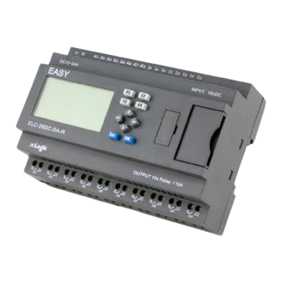
- Page 22 panel/LCD digital (I9-ID) transistors (Max.14kHz)IB,IC( 5,Q6) (NPN) Max.60k Hz) Standard ELC-26 Series CPU Units CPU with 10 relays AC 110~240V ELC-26AC-R-CAP 27-LED-indicators 16 digital (10A) COVER CPU with I9,IA 10 relays ELC-26DC-D-R-CAP 27-LED-indicators DC12V-DC24V 16 digital (Max.14kHz)IB,IC( (10A) COVER Max.60k Hz) CPU with I9,IA 8 digital/analog(I1-I8) + 8...
-
Page 23: Structure & Dimension
2.3 Structure & dimension 1. ELC-18 Series CPU 1.Power supply 2. Input 3. Program/RS232 port 4. HMI/LCD panel 5. keypad 6.Expansion+RS485 port 7.Output 2. ELC-12 Series CPU 1. Power supply 2.Input 3. Program/RS232 port 4.Extension/RS485 port... - Page 24 5.HMI/LCD panel 6.keypad 7.Output Notes: 1. Program port/RS232 port(ELC-RS232 ,ELC-USB,ELC-Copier,ELC-MEMORY should be inserted in this port) 2. Extension port(it can be used as 2 RS485 ports ,ELC12-CB-A, ELC12-CB-B should be inserted in this port) 3. ELC-E Series Expansion Module(only use with ELC-18 CPUs) 1.
-
Page 25: Chapter 3 Installing/Removing Xlogic
5. ELC-22 and ELC-26 series CPU 1. Power supply 2.Input 3. Program/RS232 port 4.HMI/LCD panel 5.keypad 6.Extension/RS485 port 7.Output Chapter 3 Installing/removing xLogic Dimensions The xLogic installation dimensions are compliant with DIN 43880. xLogic can be snap-mounted to 35 mm DIN rails to EN 50022 or on the wall. xLogic width: ELC-12 Series CPU has a width of 72mm. -
Page 26: Din Rail Mounting
3.1 DIN rail mounting Mounting How to mount a xLogic module and a expansion module onto a DIN rail: 1. Hook the xLogic Basic module onto the rail. 2. Push down the lower end to snap it on. The mounting interlock at the rear must engage. 3. -
Page 27: Wall-Mounting
Removal To remove xLogic: ..if you have installed only one xLogicr Basic: 1. Insert a screwdriver into the eyelet at the bottom of the slide interlock and move the latch downward. 2. Swing the xLogic Basic off the DIN rail.. - Page 28 Drilling template for wall-mounting Before you can wall-mount xLogic, you need to drill holes using the template shown below. ELC-12 series: All dimensions in mm Bore hole for Ø M4 screw, tightening torque 0.8 to 1.2 Nm 1. ELC-12 CPU 2.
- Page 29 All dimensions in mm Bore hole for Ø M4 screw, tightening torque 0.8 to 1.2 Nm 1. xLogic CPU 2. xLogic extensions ELC-6 series: ELC-22/26 series...
-
Page 30: Mounting Elc-Hmi-Fp
3.3 Mounting ELC-HMI-FP ELC-HMI-FP ,Faceplate ( ELC-HMI’s installation unit), making it possible for ELC-HMI to be externally installed in the front door of cabinet for easy observation and operation while ELC-12 CPU is required to be installed inside. To prepare the mounting surface for the optional ELC-HMI-FP and mount it, follow these steps: 1. - Page 31 3. Fit the ELC-HMI-FP (as the above figure ,not include the lock part) into the cutout you made in the mounting surface. 4. Attach the mounting brackets (included) to the ELC-HMI-FP. 1. Mounting brackets 2. Mounting lock 3. Cabinet door or control panel (Thickness:1.5 to 8.5 mm) 5.
-
Page 32: Wiring Xlogic
3.4 wiring xLogic Wire the xLogic using a screwdriver with a 3-mm blade. You do not need wire ferrules for the terminals. You can use conductors with cross-sections of up to the following thicknesses: 1 x 2.5 mm 2 x 1.5 mm for each second terminal chamber Tightening torque: 0.4.. -
Page 33: Connecting Xlogic Inputs
3.4.2 Connecting xLogic inputs 1. Requirements the inputs you connect sensor elements such as: momentary switches, switches, light barriers, daylight control switches etc. AC Type DC Type <40VAC <3VDC Signal status <0.24mA <1.5mA >85 VA C >8VDC Signal status Typical Typical 3mA Analogue input AI1-AI4(0-10V DC) - Page 34 Note: . For ELC-18DC-DA ,ELC-22DC-DA, ELC-26DC-DA Series and ELC-12DC-DA Series versions. That can receive analog input. They can be set to analog input or digital input as either may be used in the program. They will be recognized as analog inputs when the input terminal is connected with an analog function block, and they will be recognized as switching inputs when the input terminal is not connected with an analog function block.
- Page 35 * Analog Inputs (DC 0…10V) *Analog inputs current Inputs (0…20mA) The above figure shows how to make a four-wire current measurement. Connect two-wire sensor to ELC-E-AI(I). Two-wire sensor wiring is as follows: 1. Connect the output of the sensor to the “I” terminal (0…20mA current measurement) of ELC-E-AI(I) module.
-
Page 36: Connecting Xlogic Outputs
of power cord is proportional to +2.5 °C The three-wire technology can inhibit the influence of measurement results caused by cable length (ohmic resistance). 3.4.3 Connecting xLogic Outputs 1. Requirement for the relay output Various loads such as lamp, fluorescent tube, motor, contact, etc., can be connected to the outputs of xLogic. - Page 37 2. Requirement for the electronic transistor output: The load connected to xLogic must have the following characteristics: * The maximum switch current cannot exceed 0.3A. * When the switch is ON (Q=1), the maximum current is 0.3A. Notes (PNP): * The load connecting voltage must be ≤60VDC and it must be DC. * The “+”...
- Page 38 Notes (NPN): * The load connecting voltage must be ≤80VDC and it must be DC. * The “-” terminal of the output wiring must be connected with the DC negative voltage, and it must be connected with the “M” terminal of the xLogic power ,a load must be connected with the “+”...
- Page 39 ELC12-E-AQ-I /ELC-E-AQ-I ELC-RS485 Actually, ELC-RS485 is just a convertor with photo isolation bringing out 3 wiring terminals(short circuited inner of such 3 terminals, so only one channel RS485 bus available) from RS485 port (2x8pin) of CPU for your easy connection with other devices.
-
Page 40: Communication Port Instructions
If “RT1”, RT2” terminal are short connected, one 120R resistor will be connected between A/+ and B/- 3.4.4 Communication port instructions: ELC-18 ,ELC-22 and ELC-26 CPUs... - Page 41 1. Programming port/RS232 port(ELC-RS232 ,ELC-USB,ELC-Copier should be inserted in this port) When the programming port should be used as the standard RS232 port (D-shape 9 pin header) ,the ELC-RS232 cable needed.Blow is show you the pin definition of the header: function others NULL...
-
Page 42: Chapter 4 Parameters Modification Hmi Operation
Named COM1. When the programming port should be used as the standard RS232 port (D-shape 9 pin header) ,the ELC-RS232 cable needed. 2. Expansion port/RS485 ( pin definition(2X3 pin female figure) 1------RS485 A1 6------RS485 B1 2------RS485 A2 3------RS485 B2 4------GND 5------Battery Communication between CPU and expansion module will use 1, 6 pin. -
Page 43: Overview Of Xlogic Menu
4.1 Overview of xLogic menu Programming mode Parameter assignment mode Parameter assignment menu: 4.2 LCD panel instruction 1. Display area: 4x16 characters can be displayed (4x10 characters for ELC-12 and ELC-18 series CPU) 2. 4 X Function key: operate the program by pressing down these key (Only for ELC-22 and ELC-26 series CPU, invalid for ELC-12 and ELC-18 series CPU) 3. - Page 44 4. Display all kinds registers value(AI/AO, Parameters of blocks etc) 5. Display multiple alarming messages 6. Modify the parameters of blocks 7. Manual programming 8. Backlight can be controlled via programming(Light on Alarm) 9. System cover message can be customized 10.
- Page 45 Manual programming menu: After being powered on, xLogic shall self-check program stored in the CPU. If the program is accurate, then the CPU will be running, meanwhile the system cover will show as...
-
Page 46: Select Function Page
follows: In xLogicsoft, this interface is defaulted as its initialization screen. If there are several parameter pages, users can press key to go to the page you would like. The last page is the cursor mode: Cursor keys can be controlled in this page by press arrow keys and ESC key at the same time. If xLogic has several alarm interfaces in the same period and it only displays the message with highest priority in the function block, also you may go through all alarm messages by pressing key. - Page 47 After pressing ESC key, xLogic would be switched to function page and meanwhile open function menu as figure below shows. Brief introduction on 5 options of function page: Run/stop Select this menu to switch over xLogic status between RUN and Stop. Refer to chapter4.3.1 for details.
-
Page 48: How To Switch Run/Stop
Clock To set and modify date and time .Refer to chapter 4.3.5 for details. Menu Language To change the language of the Menu. Refer to chapter 4.3.6 for detail 4.3.1 How to switch Run/Stop You should first select FUNCTION PAGE. (Read 4.3) 1. -
Page 49: Set Parameter
4.3.2 Set parameter If you want to select a parameter, you need do as the following procedures: Under the FUNCTION PAGE, select “Set parameter”: Press 2. Confirm by pressing OK key. Then xLogic displays the first parameter, so you can modify as you like. If there is no parameter to set/modify, you can press ESC key to return. - Page 50 2. Confirm by pressing OK key. B. then you can perform the below actions to modify parameter: Move the cursor to the parameter to be modified: press key. Modify value: press key. Confirm the value after modification: press OK key. Note: When xLogic is running, not only time value but also time unit(S,M,H) can be altered , but Besides alter time parameter at RUN time ,you can alter time...
- Page 51 You can alter the time and date of switch on/off. Current value of counter In parameter mode, the parameter view of a counter: Current value of hour counter In parameter mode, the view of hour counters: You can edit configured time interval (MI). Current value of threshold trigger In parameter mode, the view of threshold trigger: You can alter the threshold value of switching on /off.
-
Page 52: Set Password
4.3.3 Set password xLogic supply password protection function for your program. You can choose according to your need. See the following instruction; you’ll understand the method of setting password. Set one password A password contains less than or equal to 4 characters and each character is Arabian number from 0 to 9 .It is easy to specify, edit or remove the password directly on the xLogic in the “Password”... - Page 53 10. Confirm password: press OK key. Now, the program is protected by the password of “1234”, and then you can return to the main menu. Note: You can cancel a password newly-set via ESC key. In this instance, xLogic will return to main menu and not reserve that password.
- Page 54 LCD displays: 4.Confirm new password: press OK key. So you have set the new password and then return to main menu. How to remove the password: In case you need to remove password .e.g. allow the other users to edit your program, then you must know the current password.
-
Page 55: How To Set Address Of Cpu And Expansion Module
you want to set password next time, the LCD will display: 4.3.4 How to set address of CPU and expansion module A. Set CPU address If there are more than one CPU in a certain communication network,well then the address of CPU must be set differently each other. - Page 56 must be different each other, otherwise the system(CPU+expansions) would run abnormal. You shall first select the FUNCTION PAGE. (Read 5.2) 1. Press key to move the cursor to “Set address”: 2. Press OK key to confirm “Set adr”: 3. Press key to move the cursor to “Set E adr:.
- Page 57 means the swith position Address 2: Address 3: Address 4: Address 5: Address 6: Address 7: Address 8: The expansion port of CPU must be open when the using extensions . Following is tell you how to open the expansion port: You shall first select the FUNCTION PAGE.
-
Page 58: Set Lcd (Backlight And Contrast)
5. Press key to select “on” Notes: 1. The address setup of the extension module must be before powering on. Modification when powering on will be ineffective. 2. Freely connection , need not care the power type between CPU and extensions ,that means the AC type module also can be connected with the DC type module. -
Page 59: Set Communication Parameters
3.Select "Backlight"menu and click "OK" 4. Default is 10 seconds, and another option is "Always On". Confirm with "OK" Modify the contrast Confirm with "OK" Modify the contrast with key, and confirm with "Ok". 4.3.6 Set communication parameters Select "Set Com" menu from the menu "Set..". - Page 60 Confirm with "Ok" COM0: RS232 port or programming port. COM1: RS485 port(For the ELC-RS485 and ELC-Ethernet module which shall be connected to ELC-18,ELC-22,ELC-26 CPU) (Customized RS485 or Ethernet module for ELC-12 CPU will also use such port) COM2: RS485 port for ELC12-E-RS485 or ELC12-Ethernet module which shall be connected to ELC-12 CPU (Customized RS485 or Ethernet module for ELC-18,ELC-22,ELC-26 CPU will also use such port)
-
Page 61: Modification Of System Time
Change it with pressing Up and Down key And confirm with "OK" Set Modbus protocol Confirm with "OK" Change with Up and Down key. And confirm with "OK" There are 4 options available: RTU, ASCII, TCP RTU, TCP ASCII. Note:If you want to use the Modbus TCP protocol, generally, you can select the "TCP RTU". - Page 62 Press OK key to set and modify date. Press key to realize the date which you want to set .After you finished your setting, press OK key to return to: If you want to set the time further, please move the cursor to” Set Time” menu, then press OK key: Here you can set week day (From Monday to Sunday) and the clock.
-
Page 63: Chapter 5 Programming Via Panel Key
Press ESC key and return to FUNCTION PAGE. Chapter 5 Programming via panel key Note: Only the standard ELC-12 series ,upgraded ELC-18 CPU , ELC-22 and ELC-26 CPU supports the programming via HMI panel key, standard ELC-18 & economic ELC-18 without such feature. Getting started with xLogic Programming refers to creating a circuit program from the xLogic Basic module. - Page 64 Each input is identified by the letter I plus a number. When you look at xLogic from the front,you can see the input terminals at the top. Only analog modules(PT100 and 0…20mA input ) have the inputs at the bottom. Each output is identified by the letter Q plus a number (ELC-E- AQ: AQ plus number).
-
Page 65: Blocks And Block Numbers
The illustration above with numbered AI inputs shows the conceptual usage of the inputs, not the actual physical markings on the module. xLogic's connectors The term connector refers to all connections and states in xLogic . The digital I/O status can be '0' or '1'. Status '0' means that the input does not carry a specific voltage. Status '1' means that the input does carry a specific voltage. - Page 66 These special functions offer you significantly greater performance: ● Pulse relay ● Up/down counter ● On-delay ● Softkey ● ..The chapter entitled " xLogic functions " gives a full list of the xLogic functions. Block representation on the xLogic Display The figure below shows a typical view of the xLogic Display.
-
Page 67: From Circuit Diagram To Xlogic Program
The figure above shows you three views of the xLogicDisplay, which represent the circuit program. As you can see, xLogic interconnects the blocks using their numbers. Advantages of block numbers You can connect almost any block to an input of the current block by means of its block number. In this way, you can reuse the interim results of logical or other operations, reduce programming effort, save memory space and clean up your circuit layout. - Page 68 the input: Step 1: The make contact S3 is interconnected in series to output Q1 and to a further circuit element. A series connection corresponds with the AND block: Step 2: S1 and S2 are connected in parallel. A parallel circuit corresponds with the OR block: Unused inputs Keep NULL connection for the unused connectors.
-
Page 69: The Four Golden Rules For Operating Xlogic
5.4 The four golden rules for operating xLogic Rule 1: Changing the operating mode ● You create the circuit program in programming mode. After power is on, and when the display shows "No Program ", press the ESC key to select programming mode. -
Page 70: Writing And Starting The Circuit Program
– Press , , or to move the cursor in the circuit program. – Press OK to change to "Select connector/block". – Press ESC to exit programming mode. ● You select a connector/block - when the cursor appears as a solid square: –... -
Page 71: The First Circuit Program
xLogic’s programming menu Here you can also move the ">" cursor by pressing . Move the ">" cursor to "Edit.." and confirm with OK. The Edit menu of xLogic Move the ">" cursor to "Edit Prg" (for editing the circuit program) and confirm with OK. xLogic now shows you the first output: The first output of xLogic You are now in programming mode. - Page 72 Translated into a xLogic circuit program this means: Relay K1 is (at output Q1) is controlled by means of an OR block. Circuit program S1 is connected to the I1 and S2 to the I2 input connector of the OR block. The corresponding layout of the circuit program in xLogic: Wiring The corresponding wiring:...
-
Page 73: Circuit Program Input
5.5.3 Circuit program input Let us now write the circuit program, starting at the output and working towards the input. xLogic initially shows the output: You will see an underscore below the Q in Q001, which is the cursor. The cursor indicates your current position in the circuit program. - Page 74 Press OK to confirm your entries and exit the dialog. The display now shows: Your complete circuit program layout: You have now entered the first block. Each new block is automatically assigned a block number. The only thing left to do is interconnect the block inputs. This is how it is done: Press OK.
- Page 75 block. The display now shows: Your complete circuit program in xLogic up to now: Now you connect input I2 to the input of the OR block: 1. Switch to editing mode: Press OK 2. Select the Co list: Press or 3.
-
Page 76: Assigning A Circuit Program Name
5.5.4 Assigning a circuit program name You can assign your circuit program a name that consists of up to 16 uppercase/lowercase letters, numbers and special characters. In the programming menu: 1. Move the ">" cursor to 'Edit..': Press 2. Accept 'Edit': Press OK 3. -
Page 77: Assigning System Cover
5.5.5 Assigning system cover Default display: The message in first and the second line can be modified/edit in the programming mode( also can be modified in xLogic) , each line contains 10 characters(each line contains 16 characters for ELC-22/26 series CPU). In the programming menu: 1. -
Page 78: Second Circuit Program
Press “ESC”… 5.5.6 Second circuit program Up to this point, you have successfully created your first circuit and assigned it a name and, if desired, a password. In this section we will show you how to modify existing circuit programs and how to use the special functions. - Page 79 You can see the OR block and the output relay Q1 we have already used in the first circuit program. The only difference is the new off-delay block. Editing the circuit program Switch xLogic to programming mode. As a reminder: 1.
- Page 80 Select your block (off-delay, see the next figure), and then press OK: Press to select BN option. Press “OK”. The B1 block previously connected to Q1 is automatically connected to the uppermost input of the new block. Note that you can only interconnect digital inputs with digital outputs or analog inputs with analog outputs.
- Page 81 In our example we do not use the reset input of the off-delay function. This is what the display should now show. Assigning block parameters Now you set the off-delay time T: 1. Move the cursor to Par, if it not already at this position: Press 2.
- Page 82 Showing/hiding parameters - the parameter protection mode If you want to show/hide the parameter and allow/prevent its modification in parameter assignment mode: 1. Move the cursor to the protection mode: Press 2. Select the protection mode: Press The display should now show: 3.
-
Page 83: Deleting A Block
This is not possible in parameter assignment mode. In this manual, the protection mode ("+" or "-") and retentivity ("R" or "/") settings are only shown in the displays where these can actually be changed. Verification of the circuit program This program branch for Q1 is now completed. -
Page 84: Memory Space And Circuit Program Size
3. Confirm 'Edit': Press OK (If required, enter your password and confirm with OK.) 4. Select 'Edit Prg': Press 5. Confirm 'Edit Prg': Press OK 6. Move the cursor to B2, the input of Q1: Press 7. Confirm with OK. 8. -
Page 85: Chapter 6 Configuring & Programming Software
5. Accept 'Memory?': Press OK The display now shows: Chapter 6 Configuring & Programming software Users who are familiar with the logic boxes of Boolean algebra can use the xLogicsoft. In fact xLogicsoft adapts the function block programming way. xLogicsoft is available as a programming package for the PC. -
Page 86: Xlogic Functions
You can add comments to the circuit program and create hard-copies. You save a copy of your circuit program to the file system on your PC, to make it directly available for any modifications. It takes only a few key actions to download the circuit program to xLogic. Under Simulate mode in xLogicsoft, you can study how to program via the panel key. -
Page 87: Cursor Keys
6.2.2 Cursor keys Up to four cursor keys are available to you. Cursor keys are programmed for the circuit program in the same ways as other inputs. Cursor keys can save switches and inputs, and allow operator control of the circuit program. -
Page 88: Permanent Logical Levels Hi And Lo
6.2.4 Permanent logical levels HI and LO Set the block input to logical hi (hi = high) to set it permanently to logical '1' or 'H' state. Set the block input to logical lo (lo = low) to set it permanently to logical '0' or 'L' state. 6.2.5 Panel Key It is the symbol of the Function key on the panel (F1—F4). -
Page 89: Shift Register Bits
6.2.6 Shift register bits xLogic provides the shift register bits S1 to S8, which are assigned the read-only attribute in the circuit program. The content of shift register bits can only be modified by means of the Shift register special function 6.2.7 Analog inputs You can use up to 36 analog inputs. -
Page 90: Af (Analog Flag)
values (data format is Signed short) between the master and slave devices. Both of the flags (digital/analog) are up to 64 can be used when programming. In your block configuration, you can assign a new number to the flag, provided this flag number does not already exist in your circuit program. The output always carries the signal of the previous program cycle. -
Page 91: Basic Functions List - Gf
6.3 Basic functions list – GF Basic functions represent simple logical elements of Boolean algebra. You can invert the inputs of individual basic functions , i.e. the circuit program inverts a logical “1” at a relevant input to a logical “0”; if “0” is set at the input, the program sets a logical “1”. The GF list contains the basic function blocks you can use for your circuit program. -
Page 92: And
(exclusive OR) (negation, inverter) BOOLEAN FUNCTION BOOLEAN FUNCTION 6.3.1 AND (Symbol in xLogic) The output of an AND function is only 1 if all inputs are 1, i.e. when they are closed. A block input that is not used (x) is assigned: x = 1. Logic table of the AND block: Input1 Input2... -
Page 93: And With Edge Evaluation
6.3.2 AND with edge evaluation (Symbol in xLogic) The output of an AND with edge evaluation is only 1 if all inputs are 1 and at least one input was 0 during the last cycle. The output is set to 1 for the duration of one cycle and must be reset to 0 for the duration of the next cycle before it can be set to 1 again. -
Page 94: Nand With Edge Evaluation
Logic table of the NAND block: Input 1 Input 2 Input 3 Input 4 Output 6.3.4 NAND with edge evaluation The output of a NAND with edge evaluation is only 1 at least one input is 0 and all inputs were 1 during the last cycle. - Page 95 6.3.5 OR (Symbol in xLogic) The output of an OR is 1 if at least one input is 1 (closed). A block input that is not used (x) is assigned: x = 0. Logic table of the OR function: Input 1 Input 2 Input 3 Input 4...
-
Page 96: Nor
6.3.6 NOR (Symbol in xLogic) The output of a NOR (NOT OR) is only 1 if all inputs are 0 , i.e. when they are open. When one of the inputs is switched on (logical 1 state), the output is switched off. A block input that is not used (x) is assigned: x = 0. -
Page 97: Xor
6.3.7 XOR (Symbol in xLogic) The XOR (exclusive OR) output is 1 if the signal status of the inputs is different. A block input that is not used (x) is assigned: x = 0. Logic table of the XOR function: Input 1 Input 2 Output... -
Page 98: Boolean Function
contact and convert it into a break contact with the help of the NOT function. Logic table of the NOT function: Input 1 Output 6.3.9 Boolean Function The BOOLEAN function gives the value of the output according to the combination of inputs. The function has four inputs, and therefore 16 combinations. -
Page 99: Basics On Special Functions
table. By selecting the Output OFF if result is TRUE option, the output takes the inverse value of the value configured in the truth table. 6.4 Basics on special functions Because of their different input designation, you can see right away that there is a difference between the special functions and basic functions. -
Page 100: Time Response
A signal at this input inverts the output signal of the block. Ral (Reset all): All internal values are reset. Parameter inputs At some of the inputs you do not apply any signals. You configure the relevant block values instead. Examples: Par (Parameter): This input will not be connected. -
Page 101: Backup Of The Real-Time Clock
Because of slight tolerances in the characteristics of electronic components, the set time T may deviate. The xLogic has a maximum tolerance of ± 0.02 %. When 0.02 % of the time T is smaller than 0.02 seconds, the maximum deviation is 0.02 seconds. Example: The maximum tolerance per hour (3600 seconds) is ±0.02%, which is proportional to ±... - Page 102 at input AI is transformed internally into range of values from 0 to 1000. An input voltage exceeding 10 V is shown as internal value 1000. Because you cannot always process the range of values from 0 to 1000 as predetermined by xLogic, you can multiply the digital values by a gain factor and then shift the zero of the range of values (offset).
-
Page 103: Special Functions List - Sf
Process Voltage Internal Gain Offset Value variable value shown (Ax) –30 –30 –30 –30 1000 –30 1000 mbar 0 1000 1000 3700 mbar 6.75 1000 3700 5000 mbar 10 1000 1000 5000 0.01 0.01 1000 0.01 1000 1000 5000 1000 10000 0.01 0.01... - Page 104 View in xLogic Name of the special function Timer On-delay Off-delay On-/Off-delay Retentive on-delay Wiping relay(pulse out) Edge triggered wiping relay Asynchronous pulse generator Random generator Stairway lighting switch Multiple function switch Weekly timer Yearly timer Counter Up/down counter Hours counter Threshold trigger Analog Analog threshold trigger...
- Page 105 Analog amplifier Analog multiplexer Pulse Width Modulator(PWM) Analog math Analog ramp PI controller Analog math error detection Miscellaneous Latching relay Pulse relay Message texts Softkey Shift register Data latching relay Modbus Read Modbus Write Memory Write Memory Read...
-
Page 106: On-Delay
6.5.1 On-delay Short description The output is not switched on until a configured delay time has expired. Connection Description Trg input The on delay time is triggered via the Trg (Trigger) input Parameter T represents the on delay time after which the output is switched on (output signal transition 0 to 1). - Page 107 Time-base Max. Min. resolution Accuracy value s (seconds) 99:99 10 ms ± 10 ms m (minutes) 99:59 ± 1 s h (hours) 99:59 1 min ± 1 min The display in programming mode (example): Valid ranges of the time base, if T = Actual value of an already-programmed function The display in programming mode (example): If the referenced block (B6, in the example) returns a value that lies out of the valid range, the value is...
- Page 108 2. Press to change the equal sign into an arrow. If it exists, the last referenced block and its timebase is shown. 3. Press to move the cursor to the "B" of the shown block, and then press to select the required block number.
-
Page 109: Off-Delay
6.5.2 Off-delay Short description The output with off delay is not reset until a defined time has expired. Connection Description Input Trg Start the off delay time with a negative edge (1 to 0 transition) at input Trg (Trigger) Input R Reset the off delay time and set the output to 0 via the R (Reset) input. -
Page 110: On-/Off-Delay
The value of "T"can be set/modified in parameter mode. For information about how to modify, refer to chapter 5.2.2 please. Select the required function by the block number. The time base is configurable. For information on valid time base ranges and parameter preset, refer to chapter 4.4.1 the On-delay topic. Timing diagram Description of the function Output Q is set to 1 momentarily with a 0 to 1 transition at input Trg. - Page 111 Parameter is the on delay time for the output (output signal transition 0 to 1). is the off delay time for the output (output signal transition 1 to 0). Retentivity on = the status is retentive in memory. Output Q Q is switched on upon expiration of a configured time T if Trg is still set.
-
Page 112: Retentive On-Delay
to 0 upon expiration of this time (output is off delayed to the input signal). The time T is reset if the status at input Trg is returns to 1 before this time has expired. 6.5.4 Retentive on-delay Short description A one-shot at the input triggers a configurable time. -
Page 113: Wiping Relay (Pulse Output)
Description of the function The current time Ta is triggered with a 0 to 1 signal transition at input Trg. Output Q is set to 1 when Ta reaches the time T. A further pulse at input Trg does not affect Ta. The output and the time Ta are only reset to 0 with a1 signal at input R. -
Page 114: Edge Triggered Wiping Relay
Data latching relay: AQ Up/Down counter: Cnt The value of "TL"can be set/modified in parameter mode. For information about how to modify, refer to chapter 5.2.2 please. Timing diagram Description of the function With the input signal Trg = 1, output Q is set to 1. The signal also triggers the time Ta, while the output remains set. - Page 115 when T has expired. Parameter The pulse width TH and the inter-pulse width TL can be provided by the actual value of another already-programmed function: Analog comparator: Ax – Ay Analog trigger: Ax Analog amplifier: Ax Analog multiplexer: AQ Analog ramp: AQ Analog math: AQ PI controller:AQ Data latching relay: AQ...
-
Page 116: Asynchronous Pulse Generator
6.5.7 Asynchronous pulse generator Description of function The pulse shape at the output can be modified via a configurable pulse/pause ratio. Connection Description Input En You enable/disable the asynchronous pulse generator with the signal at input En. Input Inv The Inv input can be used to invert the output signal of the active asynchronous pulse generator.. - Page 117 Parameter TL,TH: You can customize the pulse (TL)/ pause (TH) ratio. Retentivity set (on) = the status is retentive in memory. Output Q Q is toggled on and off cyclically with the pulse times T and T Parameter The pulse width TH and the inter-pulse width TL can be provided by the actual value of another already-programmed function: Analog comparator: Ax –...
-
Page 118: Random Generator
6.5.8 Random generator Short description The output of a random generator is toggled within a configurable time. Connection Description Input En The positive edge (0 to 1 transition) at the enable input En (Enable) triggers the on delay for the random generator. The negative edge (1 to 0 transition) triggers the off delay for the random generator. -
Page 119: Stairway Lighting Switch
Timing diagram Description of the function With the 0 to 1 transition at input En, a random time (on delay time) between 0 s and T is set and triggered. If the status at input En is 1 at least for the duration of the on delay, the output is set to 1 when this on delay time has expired. - Page 120 Determines the triggering time for the pre-warning. determines the length of the pre-warning time. Retentivity set (on) = the status is retentive in memory. Output Q Q is reset after the time T has expired. A warning signal can be output before this time has expired. Parameter The off-delay time T, the pre-warning time T! and the pre-warning period T!L can be provided by the actual value of another already-programmed function:...
-
Page 121: Multiple Function Switch
Time base Pre-warning time Pre-warning period Seconds 750 ms 50 ms Minutes 15 s Hours 15 min 1 min * makes sense only for programs with a cycle time of < 25 ms Description of the function Output Q is set to 1 with a 0 to 1 signal transition at input Trg. The 1 to 0 transition at input Trg triggers the current time and output Q remains set. - Page 122 Switch with two different functions: Pulse switch with off delay Switch (continuous light) Connection Description Input Trg With a signal at input Trg (Trigger) you set output Q (continuous light), or reset Q with off delay. Output Q can be reset with a signal at the Trg input. Input R You set the current time Ta, and reset the output to 0, with a signal at input R.
-
Page 123: Weekly Timer
Description of the function Output Q is set to 1 with a 0 to 1 signal transition at Trg. If output Q = 0, and input Trg is set hi at least for the duration of TL, the permanent lighting function is enabled and output Q is set accordingly. - Page 124 off triggers for each cam of the weekly timer. The parameter units are the days and the time-of-day. Output Q Q is set when the configured cam is actuated. Parameter You can configure a time hysteresis for each individual cam in parameter mode. For information about how to modify, refer to chapter 4.2.2 please.
- Page 125 Days of the week The prefix "D=" (Day) has the following meaning: ● M: Monday ● T: Tuesday ● W: Wednesday ● T: Thursday ● F: Friday ● S: Saturday ● S: Sunday Uppercase letters indicate a specific day of the week. A "-" indicates no selection for the day of the week.
- Page 126 (- -:- - means: No on-/off-times set). 6. Press to move the cursor to the first position of the off-time. 7. Set the off-time (in same way as in step 5). 8. Confirm your entries with OK. The cursor is now positioned on the No2 parameter (Cam2) and you can configure a further cam. Special characteristics to note when configuring The block properties window offers a tab for each one of the three cams.
-
Page 127: Yearly Timer
6.5.12 Yearly timer Caution Your xLogic must be equipped with an internal real-time clock if you are going to use this SFB. Short description The output is controlled by means of a configurable on/off date Connection Description Parameter At the No (cam) parameter you set the on and off trigger for the cam of the yearly timer. - Page 128 Example 3: Yearly mode on, Monthly mode off, Pulse off, On Time = 2008-06-01, Off Time = 2010-08-31: On June 1 of 2008, 2009, and 2010 the timer output switches on and remains on until August 31. Example 4: Yearly mode on, Monthly mode off, Pulse on, On Time = 2008-03-15, Off Time = 2010-**-**: On March 15 of 2008, 2009, and 2010, the timer output switches on for one cycle.
- Page 129 Example 6: Yearly mode off, Monthly mode off, Pulse selected, On Time = 2008-03-15, Off Time = ****-**-**: On March 15, 2008 the timer output switches on for one cycle. Because the timer does not have a monthly action or yearly action, the timer output pulses only one time at the specified On Time.
- Page 130 05: Starting in 2008, on the first day of each month the timer output switches on and switches off on the fifth day of the month. The timer continues in this pattern through the last month of 2010. Description of the function The yearly timer sets and resets the output at specific on and off times.
- Page 131 and reset again on November 19. You need to configure two yearly timers with corresponding on-times. Then logically link the outputs by means of an OR block. Result Place two yearly timer switch SFBs on your programming interface and configure the blocks as specified.
-
Page 132: Up/Down Counter
Create a logical link of the blocks via a standard OR block. The OR output is 1 if at least one of the yearly timer switches is set. 6.5.13 Up/Down counter Short description An input pulse increments or decrements an internal value, depending on the parameter setting. The output is set or reset when a configured threshold is reached. - Page 133 transitions. Input Dir Input Dir (Direction) determines the direction of count: Dir = 0: Up Dir = 1: Down Parameter On: On threshold Value range: 0...99999999 Off: Off threshold Value range: 0...99999999 StartVal: Initial value from which to begin counting either down or up. Retentivity set (on) = the status is retentive in memory.
-
Page 134: Hours Counter
the output is 0 and the pulses at input Cnt are not counted. Output Q is set and reset according to the actual value at Cnt and the set thresholds. See the following rules for calculation. Calculation rule If the on threshold >= off threshold, then: Q = 1, if Cnt >= On Q = 0, if Cnt <... - Page 135 Range of values: 0000...9999 h OT: Expired total operation time. An offset can be specified. Range of values: 00000...99999 h • When "R" is selected: Q = 1, if MN = 0; Q = 0, if R = 1 or Ral = 1 •...
- Page 136 Analog trigger: Ax Analog amplifier: Ax Analog multiplexer: AQ Analog ramp: AQ Analog math: AQ PI controller: AQ Data latching relay: AQ Up/Down counter: Cnt The value of "MI" can be set and modified in parameter mode. For information about how to modify, refer to chapter 4.2.2 please.
-
Page 137: Threshold Trigger
6.5.15 Threshold trigger Short description The output is switched on and off, depending on two configurable frequencies. Connection Description Input Fre The function count 0 to 1 transitions at input Fre. ! to 0 transitions are not counted. • Inputs I5,I6 (14KHZ)I7,I8(60kHz) for ELC-12 CPU, Inputs I9,IA (14KHZ)IB,IC(60kHz) for upgraded ELC-18,ELC-22,ELC-26 CPU •... -
Page 138: Latching Relay
Timing diagram fa = Input frequency Description of the function The trigger measures the signals at input Fre. The pulses are captured during a configurable period G_T. Q is set or reset according to the set thresholds. See the following calculation rule. Calculation rule If the threshold (On) >... -
Page 139: Pulse Relay
Timing diagram Description of the function The latching relay represents a simple binary memory logic. The output value depends on the input states and the previous status at the output. Logic table of the latching relay: Remark Status unchanged Reset Reset When retentivity is enabled, the output signal corresponds with the signal status prior to the power failure. -
Page 140: Message Text
(Trigger) input. Input S A one-shot at input S (Set) sets the output to logical 1. Input R A one-shot at input R (Reset) resets the output to logical 0 Parameter Selection: RS (input R priority), or SR (input S priority) Retentivity set (on) = the status is retentive in memory. - Page 141 Connection Description Input En A 0 to 1 transition at En (Enable) triggers the output of the message text. Input P P is the priority of the message text. 1 is the lowest, 32 is the highest priority. Quit: Acknowledgement of the message text Parameter Text: Input of the message text Par: Parameter or actual value of another, already...
- Page 142 Input P configuration From the input P, you configure the following characteristics of the message text: ● Priority ● Acknowledgement ● Message destination 1. Increase the priority to 1: Cursor on '0' + 2. Change to 'Ack': Press 3. Enable 'Ack': Press xLogic shows:...
- Page 143 "General" area Here you will find the following settings:· • Priority of the message text • Check box for message text acknowledgement "Blocks" area Shows a list of all the circuit program blocks and their parameters. "General parameters" area Shows general parameters such as the current date. "Block parameters"...
- Page 144 You arrange the message text in this area. Information entered in this area corresponds with that on the xLogic display. "Delete" button Button for deleting entries from the "Messages" area "Special characters" button Button for inserting special characters in the "Messages" area To arrange the message text From the "Blocks"...
- Page 145 B .Blocks C. Analog input value of ELC-12 CPU and extensions...
- Page 146 D. Analog output value of CPU and extensions E. F (digital flag) status...
- Page 147 F. AF(analog flag) value G. M status...
-
Page 148: Softkey
AM value 6.5.19 Softkey Short description This SFB provides the action of a mechanical pushbutton or switch. Connection Description Input En Output Q is set with a 0 to 1 signal transition at input En (Enable) and if, in addition, 'Status=On' has been confirmed in configuration mode. - Page 149 switching action of the function. Status: On or Off state that is applied in the initial cycle after program startup, is retentivity is not set. Retentivity set (on) = the status is retentive in memory. Output Q Output Q remains set 1, as long as En=1 and the status at the parameter Type = Switch and Status = On.
- Page 150 3. Change to the input mode of 'Par': Confirm with OK (the cursor is now positioned to 'Off') To change 'Par' to 'Switch' action and the initialization status after the program start: 4. To select 'Momentary pushbutton' or 'Switch' action: Press 5.
-
Page 151: Shift Register
6.5.20 Shift register Short description The shift register function can be used to read an input value and to shift the bits. The output value corresponds with the configured shift register bit. The shift direction can be changed at a special input. Connection Description Input In... - Page 152 Timing diagram Setting the Par parameter View in programming mode: Press This special function is not available in parameter assignment mode. Description of the function The function reads the value of input In with a positive edge (0 to 1 transition) at input Trg (Trigger). This value is written to shift register bits S1 or S8, depending on the set shift direction: •...
-
Page 153: Analog Comparator
Q outputs the value of the configured shift register bits. If retentivity is not enabled, the shift function restarts at S1 or S8 after a power failure. Note The special function shift register can be used only once in the circuit program. 6.5.21 Analog comparator Short description The output is set and reset depending on the difference Ax - Ay and on two configurable thresholds. - Page 154 Parameter p (number of decimals) The on threshold On and the off threshold Off can be provided by the actual value of another already-programmed function: Analog comparator: Ax – Ay Analog trigger: Ax Analog amplifier: Ax Analog multiplexer: AQ Analog ramp: AQ Analog math: AQ PI controller: AQ Data latching relay: AQ...
- Page 155 Q = 1, if (actual value Ax - actual value Ay) > On Q = 0, if (actual value Ax - actual value Ay) ≤Off. • If threshold On < Threshold Off, then Q = 1, falls: On ≤ (actual value Ax - actual value Ay) < Off. Reducing the input sensitivity of the analog comparator You can delay the output of the analog comparator selectively by means of the "on delay"...
-
Page 156: Analog Threshold Trigger
Configuration (example): Reducing the input response of the analog comparator You can selectively delay the output of an analog comparator by means of the "On-delay" and "Off-delay" special functions. With on-delay, output Q is only set if the pulse width of the triggering signal at input Trg (=analog comparator output) is longer than the on-delay time. - Page 157 Connection Description Input Ax Input the analog signal to be evaluated at input Ax. Use the analog inputs AI1...AI8, the analog outputs AQ1 and AQ2. 0 - 10 V is proportional to 0 - 1000 (internal value). Parameter A: Gain Range of values: ±...
- Page 158 Description of the function The function reads the value of the signal at the analog input Ax. This value is multiplied by the value of parameter A (gain). Parameter B (offset) is added to the product, hence (Ax ∙Gain) + Offset = Actual value Ax. Output Q is set or reset depending on the set threshold values.
-
Page 159: Analog Amplifier
View in parameter assignment mode (example): 6.5.23 Analog amplifier Short description This SFB amplifies an analog input value and returns it at the analog output. Connection Description Input Ax Input the analog signal to be amplified at input Ax. Use the analog inputs AI1...AI8, the analog outputs AQ1 and AQ2. - Page 160 Range of values: ± 10.00 B: Zero offset Range of values: ± 10000 p: Number of decimals Range of values: 0, 1, 2, 3 Output AQ Analog output Value range for AQ: -32768...+32767 Parameter p (number of decimals) Applies only to the display of Ax and Ay values in a message text. Does not apply to the comparison of On and Off values! (The compare function ignores the decimal point.) Description of the function...
- Page 161 Short description This special function saves the process variable of an analog input to memory, and sets the output when the output variable exceeds or drops below this stored value plus a configurable offset. Connection Description Input En A positive edge (0 to 1 transition) at input En saves the analog value at input Ax ("Aen") to memory and starts monitoring of the analog range Aen ±...
- Page 162 Description of the function A 0 to 1 transition at input En saves the value of the signal at the analog input Ax. This saved process variable is referred to as Aen". Both the analog actual values Ax and Aen are multiplied by the value at parameter A (gain), and parameter B (offset) is then added to the product, i.e.
-
Page 163: Analog Differential Trigger
6.5.25 Analog differential trigger Short description The output is set and reset depending on a configurable threshold and a differential value. Connection Description Input Ax You apply the analog signal to be analyzed at input Ax. Use the analog inputs AI1...AI8, the analog outputs AQ1 and AQ2. - Page 164 Timing diagram B: Function with positive difference Delta Description of the function The function fetches the analog signal at input Ax. Ax is multiplied by the value of the A (gain) parameter, and the value at parameter B (offset) is added to product, i.e.
-
Page 165: Analog Multiplexer
View in parameter assignment mode (example): 6.5.26 Analog multiplexer Short Description This special function displays 0 or one of 4 saved analog values on the analog output. Connection Description Input En 1 on input En (Enable) switches, dependent on S1 and S2, a parameterized analog value to the output... - Page 166 0 on input EN switches 0 to the output AQ. Inputs S1 S1 and S2 (selectors) for and S2 selecting the analog value to be issued. S1 = 0 and S2 = 0: The value 1 is issued S1 = 0 and S2 = 1: The value 2 is issued S1 = 1 and S2 = 0: The value 3 is issued...
-
Page 167: System Cover
Description of Function If input En is set, then the function issues one of 4 possible analog values V1 to V4 at the output AQ, depending on the parameters S1 and S2. If the input En is not set, then the function issues the analog value 0 at output AQ. Analog output If you interconnect this special function with a real analog output, note that the analog output can only process values between 0 and 1000. - Page 168 hence system cover can be available if you follow the below procedures : use your mouse to left-click “Tools” menu->select “Edit Cover HMI” by left-click in xLogicsoft . Short description Display the status (Run or Stop) of xLogic when power-on or simulation by soft. Particular characteristics to be noted when configuring 1."General"...
-
Page 169: Pulse Width Modulator (Pwm)
6.5.28 Pulse Width Modulator (PWM) Short Description: The Pulse Width Modulator (PWM) instruction modulates the analog input value Ax to a pulsed digital output signal. The pulse width is proportional to the analog value Ax. connection Description A positive edge (0 to 1 transition) at input En enables the PWM function block. - Page 170 Analog ramp: AQ PI controller: AQ Analog math: AQ Data latching relay: AQ Up/Down counter: Cnt Parameter p (number of decimals) Parameter p applies only to the display of the Ax value in a message text. Description of the function The function reads the value of the signal at the analog input Ax.
- Page 171 Calculation rule Q = 1, for (Ax – Min) / (Max – Min) of time period PT Q = 0, for PT – [(Ax – Min) / (Max – Min)] of time period PT. Note: Ax in this calculation refers to the actual value Ax as calculated using the Gain and Offset. Min and Max refer to the minimum and maximum values specified for the range Special feature.
-
Page 172: Analog Ramp
1. The periodic time must be no less than 3 ms. 2. If the specific output is selected in the property dialog box of PWM block, then the output pin of PWM function block cannot be linked as input to other blocks. Q3, Q4 in the above dialog box are exactly corresponding to Q3, Q4 of ELC-12 CPU and Q5,Q6 of ELC-22/26 and upgraded ELC-18 CPUs Setting the Par Parameter... - Page 173 Level1 and Level2: Levels to be reached; value range for each level: -10,000 to +20,000 parameter MaxL: Maximum value that must not be exceeded. Value range: -10,000 to +20,000 StSp: Start/Stop offset: value that is added to Offset "B" to create the start/stop level. If the Start/Stop offset is 0, then the start/stop level is Offset "B").
- Page 174 Description of function If the input En is set, then the function sets the value StSp + Offset "B" for 100 ms. Then, depending on the connection of Sel, the function runs from the level StSp + Offset "B" to either level 1 or level 2 at the acceleration set in Rate.
-
Page 175: Analog Math
6.5.30 Analog Math Short Description The analog math block calculates the value AQ of an equation formed from the user-defined operands and operators. Connection Description Input EN Enable the analog math function block. Parameter V1:Value 1: First operand V2: Value 2: Second operand V3: Value 3: Third operand V4: Value 4: Forth operand Operator 1: First operator... - Page 176 Analog multiplexer: AQ Analog ramp: AQ Analog math: AQ PI controller: AQ Data latching relay: AQ Up/Down counter: Cnt Parameter p applies to the display of V1, V2, V3, V4 and AQ in a message text. Description of the function The analog math function combines the four operands and three operators to form an equation.
-
Page 177: Analog Math Error Detection
-(H) /(L) +(M) Equation: (100 – 25) / (2 + 1) Result: 25 Setting the Par parameter The following illustration shows the view in programming mode that corresponds to the first example (12 + (6 / 3)) - 1: Use the keys to navigate between the operand value, operator, and operation priority. - Page 178 referenced analog math function block. Parameter Referenced FB The value for the Referenced FB parameter references the block number of an already-programmed analog math function block. Description of the function The analog math error detection block sets the output when the referenced analog math function block has an error.
-
Page 179: Modbus Read
Overflow Zero division OR Overflow Zero division OR Overflow Zero division OR Overflow Zero division OR Overflow If the Referenced Analog Math FB is null, then the output is always 0. Setting the Par parameter The parameters MathBN, AutoRst, and Err can be set in programming mode or parameter assignment mode. - Page 180 Connection Description Input En A high signal at En input will enable “Modbus Read” function block to be activated Input R Reset the value read from peripheral and set the output to 0 via the R (Reset) input. Reset has priority over En Parameter Slave address: 1 is default .
- Page 181 When you put the “Modbus read” or “Modbus Write” function block in your program and make some configurations, the function that xLogic serves as master will be realized. The Property in dialog box of “Modbus Read” shows as below figure: 1.
- Page 182 Command Function description remark Read one group coil status(00000~0XXXX) Read Coil Status(output) Fetch one group data of the status of switch input Read input Status (input relay) (10000~1XXXX) Read data of multi-holding register(40000~4XXXX) Read Holding Registers (Output register) Read data of input registers (3000~3XXXX) Read Input Registers Note: Please use “03”...
- Page 183 If count was set 4, the Q1,Q2,Q3,Q4 of xLogic (station No.1) will be read and save to F1 to F4 F is bit type flag. It can be used to receive bit data from slave device. Example 2 : Get AI value from Slave 2(xLogic with station No.2) and save the data to AQ11...
- Page 184 The number setting of Q,I,AQ are continuous .AQ12 cannot be set as AQ 12 and should be set AQ 4 as above figure shows. The following table shows how to set. Note: this table also can be applied for the configuration of Modbus Write function block. Model I,Q,AI,AQ Dialog box set...
-
Page 185: Modbus Write
……………. Data format instruction 6.5.33 Modbus Write Short description: When a high level in En, the Modbus Write block will be activated and the xLogic could communicate with peripheral as a master via RS232 or RS485 interface, further the output will be switched on when the communication is established successfully. - Page 186 06 Write Single Register 15 Write Multiple Coils 16 Write Multiple Registers Register start address, count Output Q Q is set or reset depending on the communication status. Successful communication , Q=1; Failed communication ,Q=0; The Property in dialog box of “Modbus Write” shows as below figure: 1.
- Page 187 Force the switch status of single coil(00000~0XXXX) Force Single Coil (output) Pre-set the data of single register Set single output register (40000~4XXXX) Force multi-coils on/off bit(00000~0XXXX) Write multi-holding registers data(40000~4XXXX) 4. Where is to save the pre-configuration data that would be written to Slave. It contains 2 kind ways to pre-configuration.
- Page 188 I1of master is used to control the communication .If I1 is high and the communication is established successfully, one alarm message (text message block) will be displayed on LCD. Then the Q1 of slave No.1 will be controlled by I2 of master. If I2 is high, Q1 of slave No.1 would be ON and if I2 is low, Q1 of slave would be OFF.
- Page 189 The above configuration is to force Q1, Q2, Q3 of Slave No.1 ON. " " means pre-set the BIT 1 and " " means pre-set the BIT 0 ”Coil 0” is corresponding to the start address ,Here is Q1. Note: The manual input value is Hex data .it contains 4 bytes. If you want to write a decimal value to the register of SLAVE, please convert it to Hex format.
-
Page 190: Data Latching Relay
Data format instruction For the detail information about I, AI, Q, AQ, registers address of xLogic ,refer to the RTU protocol file. 6.5.34 Data latching relay Short description This special function saves the process variable of an analog input to memory, and returns it at the analog output. - Page 191 analog Output AQ is reset if S and R are both set (reset has priority over set). Output AQ Analog output Value range for AQ: -32768...+32767 Example When I1 turn to HIGH, the value of AI2 will be saved to memory and return it to AQ1 as follows: When the I3 turns to HIGH, the value of this function block will be reset to 0.
-
Page 192: Pi Controller
6.5.35 PI controller Short Description It is proportional-action and integral-action controllers. You can use both types of controller individually or combined. Connection Description Input A/M Set the mode of the controller: 1: automatic mode 0: manual mode Input R Use the input R to reset the output AQ. As long as this input is set, the input A/M is disabled. - Page 193 Timing Diagram The nature, manner and speed with which the AQ changes depends on the parameters KC and TI. Thus, the course of AQ in the diagram is merely an example. A control action is continuous; therefore the diagram portrays just an extract. A disturbance causes the PV to drop, as Dir is positioned upwards, AQ increases until PV corresponds again to SP.
- Page 194 If the updated value PV = SP, then the special function does not change the value of AQ. Dir = upwards/+ (timing diagram numbers 1 and 3) • If the updated value PV > SP, then the special function reduces the value of AQ. •...
- Page 195 Full level 1 Vat and/or reservoir filling without drain Full level 2 Vat and/or reservoir filling with drain Characteristics when configuring Observe the Control and regulate basics. Control and regulate In engineering, quantities can be both controlled and regulated. When controlling, a quantity is manipulated without being able to compensate for outside influences. When regulating, a quantity is maintained at a specific value in order to compensate for outside influences.
- Page 196 (thermometer), compares the process value (room temperature) with the command variable (desired room temperature) and uses the actuator (changeable resistance) to manually regulate the manipulated variable (heating current), in order to compensate for the disturbance variable (temperature drop from opening the window). The person is therefore the controller. The control device is formed from the actuator and the control.
- Page 197 Control loop The process value x influences the manipulated variable M by means of the regulating device. This creates a closed circuit that is also known as a control loop. If, in the example above, the window is opened, the temperature in the room drops. The person must increase the heat output of the heater.
- Page 198 A proportional-action controller (P controller) changes the manipulated variable M proportional to the loop error. The P controller works immediately. By itself it cannot drive the loop error to zero. :Manipulated variable of the P controller at the time n :Gain of the P controller : Loop error at the time n The following picture shows a jump in process value and step response of the controller:...
- Page 199 : Loop error at the time n : Loop error at the time n-1; etc. : Loop error at the beginning of the calculations The following picture shows a jump in process value and step response of the controller: Summary The PI controller has the following characteristics: It sets the process value exactly to the command variable.
- Page 200 : Sampling time, duration of a time slice : Integral time; by means of this time the influence of the integral part is controlled on the manipulated variable, also known as the integral-action time : Loop error at the time n The following picture shows a jump in process value and step response of the controller: Summary The PI controller has the following characteristics:...
- Page 201 0 and kI = 1 If KC <> 0: kP = kI = KC Ts Sampling time, Fixed 500 ms duration of a time slice TI Integral time Parameter TI, if you set this 00:01 min to 99.59 min parameter to 99:59 min, then you switch off the I part of the controller.
-
Page 202: Memory Write
The Dir parameter gives the action - or + direction of the controller. Positive means: If set value > process value then the process value is increased; if set value < process value then the process value is reduced. Negative means: If set value > process value then the process value is reduced;... - Page 203 Description of Memory write block’s property dialog box : 1. File name Place where you can set the name of the file used to save the registers’ data 2. Record title Below is an example in the “OUTPUT.TXT” The above range circled in red is just pre-set contents in the “Record title” of the Memory write block’s property dialog box.
- Page 204 box has been ticked ,the file content will show the time when the data starts to be recorded. 4. Separator Such separator shall be required while more than one analog values would be stored and displayed for easier observation and convenient analysis. 5.
- Page 205 Name Address: F1-F64 0….63 D. M Name Address: M1-M512 0….511 AI analog inputs Name Address: AI1-AI8 0….7 AI11-AI14 8---15 AI21-AI24 16…23 ….. …… G. AQ analog outputs Name Address: AQ1-AQ2 0….1 AQ11-AQ12 2---3 AQ21-AQ22 4…5...
- Page 206 ….. …… AF analog flag Name Address: AF1-AF64 0….63 I. AM Name Address: AM1-AM512 0….511 EXAMPLE:...
- Page 207 Please refer the property dialog box of B003, it can record the output status .The start address is from 0 and it must record the 20 outputs with continuous addresses. And the record file shows below: Per the program, every 6 seconds the record will do once, and the Q1, Q2, Q3, Q4, Q11 will be all “ON”. You can see the record file and you’ll see the recording time and the status of the output.
-
Page 208: Memory Read
port for some purposes (for example download or upload program) , you must make sure the Trg pin of this block keeps at Low status or stop the CPU by panel key. 6.5.37 Memory Read Short Description Only when there is a low to high trigger at Trg pin, the Memory Read block will be activated once and xLogic CPU will read correlative data (bit or short) to set pre-configured register from the file in the SD card of ELC-MEMORY module, at the same time the output will switch on if the read action had been done successfully. - Page 209 1. File name The name of the file which you want to access is stored in the mini-SD card of the ELC-MEMORY module. 2. Record Title Below is an example in the “OUTPUT.TXT” 3. Data Type: Two options available: Option A. BIT (0 or 1, this is used to be set the status of Q or F ) Option B .
- Page 210 Q21-Q24 16…23 ….. …… F: digital flag Name Address: F1-F64 0….63 WORD data can be used to set the register “AQ” and “AF” AQ analog outputs Name Address: AQ1-AQ2 0….1 AQ11-AQ12 2---3 AQ21-AQ22 4…5 ….. …… AF analog flags Name Address: AF1-AF64 0….63...
- Page 211 If the Memory Read block had been triggered, the Q1 of ELC-12 CPU will be set “1”.
-
Page 212: Word To Bit
6.5.38 Word to Bit Short description This special function is used to transfer the word type data (AI, AF or AQ) to 16 bit status (0 or 1)(F or Q) Connection Description Input En Enable this function. Input R Reset output Q with a signal at input R (Reset). Parameter Retentivity set (on) = the status is retentive in memory. -
Page 213: Xlogicsoft
Example2: Convert the counter value (5) to Q1,Q2 and F1--F14(0000000000000101) 6.6 xLogicsoft xLogicSoft xLogicsoft runs under Windows 95/98, Windows NT 4.0, Windows Me®, Windows 2000®, Windows XP®,windows Vista xLogicsoft is capable of client/server operation and offers you a high degree of freedom for creating your circuit program. xLogicSoft: xLogicV3.0.0.7 This is the current version of xLogicsoft. - Page 214 Installing xLogicsoft: 1. Double-click on Setup.exe or left-click the “INSTALL” menu directly. 2. Select the language you would like and click OK to confirm 3.If you consent to the license agreement, click Next to confirm. 4. Where is the program to be installed? If you do not want to accept the recommended file location: C:\Program Files\EASY\xLogicsoft, specify another directory using Browse.
- Page 215 5. If you want to accept the recommended file location, click Next to Confirm. 6. In this example, the program icon is to be placed on the desktop. Use Next to proceed.
- Page 216 7.Click Install button to install. Program is being installed..
- Page 217 8. The installation is finished. You can start the xLogicsoft immediately or later by double-clicking the icon on the desktop.
- Page 218 You now see the complete user interface of xLogicsoft The programming interface for creating your circuit programs occupies the greater part of the screen. The icons and logical links of the circuit program are arranged on this programming interface. To help you to maintain an overview of large circuit programs, the right side and the bottom of the programming interface contains scroll bars, which you can use for vertical and horizontal scrolling of the circuit program.
-
Page 219: Main Functions
6.7 Main Functions 1. Edition function The main function of xLogicsoft is programming for xLogic. By using the Logical Function Edition window of xLogicsoft, you can create and edit your desired xLogic programs using various function blocks of xLogic and can also perform file operations such as save, print, program management etc. -
Page 220: Menu Bar
6.8.1 Menu Bar When xLogicsoft is used to edit xLogic programs under customized mode, some basic operations including files management, opening and closing of the Tool Bar and Status Bar access to Help information are completed by using pull-down menu under File, Edit, Tools, SMS, View and Help. The Instruction Function list of xLogicsoft is characterized by its flexibility and variation according to the main selection. -
Page 221: Edit
6.8.1.2 Edit Fig. 10.2 Edit Menu ※ Undo: Undo the previous step operation and support consecutive operations. ※ Redo: Recover the contents undone by the previous step of operation and support consecutive operations. ※ Cut: Cut the contents in the area highlighted with the cursor. ※... -
Page 222: Sms
Fig. 10.3 Tools Menu ※ Configuration: Select and open the Com port. ※ Disconnect Line: Cancel the connection of PC and xLogic. ※ Transfer: Transfer the following data between PC and xLogic. PC-> PLC: Download the program to xLogic PLC->PC: Upload the program from xLogic. Password set: Set Password protection to xLogic Get PLC Version: Get the current xLogic hardware version Set Clock: Set RTC for xLogic... - Page 223 Generally, you are not required to fill out the GSM provider, because the xLogic unit can automatically search it. But the GSM servers centre number need manually input and the xLogic also can save it. The SIM card can be protected with a PIN code just like for normal cell phone use. The PIN request is activated and the PIN code is inputted in the required field.
-
Page 224: View
6.8.1.5 View This instruction is to display the status bar, workspace and the Information window and so on. The pull down menu is shown as the following: Fig. 10.5 View Menu ※ Status bar: state bar displaying instruction ※ Workspace: workspace displaying instruction ※... -
Page 225: Toolbar
6.8.2 Toolbar The icons of the standard toolbar provide quick access to commands that are also available on the menu. Standard Toolbar Zoom In Open Zoom Out Save Align Left Save All Align Right Align Top Copy Align Bottom Paste Page Layout Tab Undo Open COM port... - Page 226 Text Tool Cut/Join Connector Tool Constants and Terminals Basic functions Special functions Simulation On-line test Selection Tool You can use the selection tool to select and move blocks, text and connecting lines. You can select objects individually with a left-click; you can select multiple objects with [Ctrl]+Click, or you can use the mouse as a "lasso"...
-
Page 227: Simulation Tool And Status Window
6.8.4 Simulation Tool and status window A toolbox pops up when you open the simulation mode. It contains: • Icons (e.g. switches) for operator control of the inputs . • An icon for the simulation of a power failure, for testing the switching response with reference to retentivity characteristics after power failure. - Page 228 Status display Layout of inputs The inputs are displayed in the form of key or switch icons. The name of the input is displayed below the icon. An open input represents an inactive switch. When you click on the icon, it is indicated active and the switch is shown in closed state.
-
Page 229: Basic Operation
Prerequisite: The display of signal states and process variables is enabled under Tools Simulation. The colored indication lets you identify the "1" or "0" status of a connecting line. Default color of connecting lines carrying a "1" signal is red. Default color of connecting lines carrying a "0" signal is blue. 6.9 Basic Operation This chapter will tell you how to write logic function graph Program with xLogicsoft, how to simulate the Program you write with xLogicsoft, how to communicate between PC and xLogic with xLogicsoft, how to... - Page 230 Fig.7. 9.1 Open New Document Notes: An option Window of outside-meet extended module will appear before a new document opened. Fig.7. 9.2 Hardware type selection Page layout set and hardware selection before programming In the Page Layout tab, you can specify how and on how many pages to print your circuit program. You can preview the pagination in this tab.
-
Page 231: Open Existed Document
Click the payout icon or double click the model displayed area on the right down of the interface, the model selection dialog box also can pop out 6.9.1.2 Open Existed Document Operation Method: 1. To open a document, click ‘Open’ option of menu ‘File’ once with left button of mouse ,or click once in toolbar, shortcut key ‘Ctrl+O’... -
Page 232: Edit Function Diagram Program
6.9.2 Edit Function Diagram Program 6.9.2.1 Place Function Block While you set up a new document, you can write your control Program in the new program interface. The method and process of placement is as follows: The method of placing function block is as follows: choose function block needed from the workspace left of the program interface. -
Page 233: Setup Link
Fig 7.10.2 Block edit menu 2. Property dialogue box, as shown in Fig 7.10.3, to setup each item of content according to what you need, you also could click “Help” to observe the detail instruction. Fig 7.10.3 property box Note: Different block has different property setup, especially the property of special function module. - Page 234 link. 2. To do so, move the mouse pointer to a block input or output and press the left mouse button. Keep the mouse button being pressed down and then drag the mouse pointer from your selected source terminal to the target terminal. Now release the mouse button to anchor the connecting line to both terminals. While the connecting line is being drawn, it is shown as a straight line between the first terminal and the mouse pointer.
-
Page 235: Delete Function Block Or Delete Link
Tips on connecting blocks 1. Move the mouse pointer over a block and briefly hold it in this position. The name of the block is shown. The name of the block input appears when you move the mouse pointer onto the input. 2. - Page 236 Fig. 7.10.6 Start simulation 2. Click input block with mouse. It can change the state of input, state displays “ON” and “OFF” in the output point of the module, so you can observe the state of input or output. 3. Click button again, to terminate the operation function of the module.
-
Page 237: Save And Print
the program to see if it performs control requirement or not. 6.11 Save and Print Operation method of file saving 1.To save a Program, click option “save” or “Save As” under menu “File” with left button of the mouse, as shown in Fig.7.10.8, or click button “ ”under toolbar. -
Page 238: Modify Password And Transfer The Program
Fig. 7.10.9 File Print 6.12 Modify Password and transfer the Program Operation Method: a. First of all, link xLogic with your PC through the optional way: RS232 cable, USB cable (need install driver first), Ethernet connection. b. Open application software xLogicsoft, set up a new document, then open computer com. Click option “Configuration”... - Page 239 Operation method of setup password a. Click “Tools->transfer-> Password set” with left button of mouse, dialog box shown as Fig.7.10.11 appears: Fig. 7.10.11 Modify password You can modify communication password of your xLogic mainframe in this dialog box. b. Input new password in edit box after “New Password”, “write to xLogic. II.
-
Page 240: On-Line Monitoring/Test Circuit Program
c. Click option “transfer->PC->xLogic” under menu “Tools”; or click button “ ”in toolbar d. Click button “ ” with left button of mouse, start update Program, downloading status shown as Fig. 7.10.14 display update Program course. Fig. 7.10.14 downloading status Attn: After the Program update, xLogic will run the Program automatically, need not restart. - Page 241 Under monitor mode, user can change the spare output (the input pin of Q is not connected to other blocks) state via xLogicsoft. Right click "Q2" and then click "Set Output State".
- Page 242 Click "OK" button and the Q2 of xLogic will be turned off. How to transfer monitoring data (AI/AQ) to an Excel file ? Example program: 1. Select Tools-> Set Monit Config and further click it.
- Page 243 As below configuration shows, all history data of AI/AQ under monitor mode can be automatically saved to one EXCEL file for user’s reference. Caution: If the “clear previous data” is selected as well, then the history data cannot be saved, and then only the current monitor data can be saved, furthermore, the history data (previous monitor data) would be simultaneously cleared.
- Page 244 4. Click to transfer data into one excel file (it contains AI1/AQ number, value and the corresponding time.).
-
Page 245: Chapter 7 Applications
Chapter 7 Applications In order to let users know the far going application field of xLogic, we present a set of application example. Each instance includes the circuit program of its original solution and the compare of solution in which xLogic has been applied. - Page 246 7.1.1 Standard solution Up to now two methods were known to control such a lighting system: Pulse relay: When the lights are off, press any of the pushbuttons to switch on the lights. When the lights are on, press any of the pushbuttons to switch off the lights again. Disadvantage: People often forget to switch off the lights Automatic stairway light switch: Press any one of the pushbuttons to switch on the lights.
- Page 247 You can also implement both functions (off delay timer and pulse relay) in a single unit. What is more, you can incorporate extra functions without making any alterations to the wiring. In our example program, we have combined the advantages of both the current impulse relay and the automatic stairway lighting timer as follows: •...
-
Page 248: Automatic Gate
If input “I1”has a pulse, the output Q1will be on and keep 6 minutes, then be off. Apply xLogic to realize multiple switches When the input “I1” has a pulse, the output “Q1” will be on and not off until the period“TH”be over. Keep the momentary switch holding down in period “TL”, the light will be on all the time. -
Page 249: Standard Solution
7.2.1 Standard solution As long as the detector B1 or B2 detects someone approach, the switch K3 will be on and open the door. If the two detectors don’t detect person in a short time, trigger K4 and close the door. -
Page 250: The Scheme Of Xlogic
7.2.2 The scheme of xLogic Required components: open contactor close contactor S1(break contact) close limit switch S2(break contact) open limit switch B1(make contact) outdoor infrared action detector B2(make contact) infrared action detector inside xLogic function block circuit program: Motion detector During business hours, if someone enters store, the detector B1 will trigger electric motor to open the door, vice versa. -
Page 251: Ventilation System
customer to leave. Trigger electromotor for opening door The output Q1 is switched on and triggers electromotor, when: Operate control switch I5(the door is open all the time) The detector indicates that somebody is approaching to the door. The door has not been opened entirely (I4 limit switch is not off.). Trigger electromotor for closing door Operate control switch I6(the door is closed all the time ) The detector indicates that nobody is approaching the door. -
Page 252: Standard Solution
Requirements for a Ventilation system A Ventilation system supplies fresh air into a room and exhausts the contaminated air. Let us look at the following sample system: • A room contains an extractor fan and a fresh-air fan. • Each fan is monitored by means of a flow sensor. •... -
Page 253: The Scheme Of Xlogic
The fans are monitored by means of flow sensors. If no air flow is registered after a short delay time has expired, the system is switched off and an error message is generated, which can be acknowledged by pressing the off button. Fan monitoring requires an analyzer circuit with several switching devices, in addition to the flow sensors. - Page 254 S2(break contact) Flow monitor S3(break contact) Flow monitor Flashing lamp Flashing lamp xLogicSoft solution The use of xLogic reduces the amount of switchgear. Thus, you save installation time and space in the control cabinet. You may even be able to use as a smaller control cabinet. With xLogic you can also switch off of the fans sequentially after the system is switched off.
-
Page 255: Factory Door
7.4 Factory door Requirements for a gate control system In many cases a factory entrance is closed with roll gates. Those gates are only opened when vehicles need to enter or leave the factory grounds. The gate is controlled by the porter. The sliding gate is opened and closed by means of a pushbutton control in the gatehouse. -
Page 256: The Scheme Of Xlogic
7.4.2 The scheme of xLogic The circuit diagram of industry gate:... - Page 257 Required components: Main contactor Main contactor S0 (break contact) Off button S1 (make contact) Open button S2 (make contact) Shutdown button S3 (break contact) Open position sensor S4 (break contact) Shutdown position sensor S5 (break contact) Safety bar xLogicSoft solution A xLogic circuit provides a further feature compared to standard controls: The actuation of a safety bar interrupts the closing motion of the gate.
-
Page 258: Daylight Lamp System
7.5 Daylight lamp system Requirements for lighting system: Different daylight lamp rows should be able to be switched on and off handily. If window at one side has enough light, the light will be switched off automatically via lightness sensitivity switch. The light would be switched off automatically at 8:00 p.m. -
Page 259: The Scheme Of Xlogic
Daylight control switch B1 Timer T1 Pulse relay K1 and K2 pulse switch K3—K6 able to be switched off collectively Disadvantages of traditional solution: In order to realize function, it needs plenty of wiring. Vast mechanical parts will result in obvious abrasion and high maintenance costs. Modification function can cause much work. -
Page 260: Rainwater Pump
Benefits: While power consumption of load does not exceed output of switch’s voltage range, lamp can be directly connected to xLogic main module; however, if power consumption of load exceeds output of switch’s voltage range, then power contactor would be required. You can connect directly lightness sensitivity switch to the input of xLogic. -
Page 261: Standard Solution
Wash clothes Water system in garden Potted plant water Wash car Scour W.C. The following figure is to tell you how to run the rainwater application system: The rain water is collected in the container and then pumped to service water ductwork through pumping station. -
Page 262: The Scheme Of Xlogic
7.6.2 The scheme of xLogic Components: main contactor Solenoid valve Pressure switch S2(make contact) Bobber switch(water level) S3—S4(break contact) Bobber switch(water level) Function block diagram:... -
Page 263: Chapter 8 Modbus Function Code And Register Addresses
Chapter 8 Modbus function code and Register addresses 8.1 xLogic modbus function code The following table contains some communication orders supported by xLogic. Length Order Function description message(one frame Remarks code(Hex) order can deal with) Read one group coil status ( 00000 ~ Read Coil Status... -
Page 264: Register Addresses Of Xlogic
8.2 Register addresses of xLogic Communication parameters settings: PLC mode selection:MODBUS RTU Communication parameter set: Baud rates:9600 Data bit:8 Stop bit:1 Name Set address method Data format Attribute (DECIMAL) Digital quantity input ELC-6(CPU): switch ELC-18(CPU): 0~11 ELC-E-16(EXT1): 12~19 ELC-E-16(EXT2): 20~27 Function Block in ELC-E-16(EXT3) - Page 265 Sms Input ELC-SMS-D-R 260~265 (SmsI1-SmsI6) Function (1x) code 02 Sms Message Input ELC-SMS-D-R (MsgI1-MsgI10) 266~275 Function (1x) code 02 Coils outputs ELC-6(CPU): ELC-18(CPU): 0~5 ELC-E-16(EXT1): 8~15 Function ELC-E-16(EXT2): 16~23 code ELC-E-16(EXT3): 24~31 01/05/15 ∙ ∙ (0x) ∙ ∙ ∙ ∙ EXM-12/ELC-12(CPU):...
- Page 266 Middle coil ELC-6&EconomicELC- (0x) 12 Series: 256~319 Function code 01 Standard EXM-12/ ELC-12 Series: 256~767 (0x) Standard/ economic ELC-18 Series: 256~511 Upgraded ELC-18 Series: 256~767 ELC-22/26 256~767 F outputs ELC-6&Economic ELC-12 Series: 1536~1567 Function code EXM-12/Standard 01/05/15 ELC-12 : 1536~1599 (0x) ELC-18 Series: 768~799...
- Page 267 Holding register(timer、 ELC-6&Economic LONG counter value) ELC-12 Series: (4x) 0~63 EXM-12/ ELC-12 Series: 0~511 ELC-18 Series: 0~255 (4x) Upgraded ELC-18 Series: 0~511 ELC-22/26 0~511...
- Page 268 Analog quantity input EXM-12/ Signed short register ELC-12 Series: (1024~1279) CPU:1024~ 1031 EXT1:1032~ 1039 (4x) EXT2:1040~ 1047 ………… ELC-18 Series: (256~511) CPU:256~263 EXT1:264~ EXT2:272~ ….. Upgraded ELC-18 Series: CPU:1024~ 1031 EXT1:1032~ 1039 EXT2:1040~ 1047 ELC-22/26 (CPU) :1024~ 1031 EXT1:1032~ 1039 EXT2:1040~ 1047...
- Page 269 Analog quantity output EXM-12/ Signed short buffer ELC-12 Series: (1280~1535) CPU:1280~1281 EXT1:1282~1283 EXT2:1284~1285 ELC-18 Series: (4x) (512~531) CPU:512~513 EXT1:514~515 EXT2:516~517 ELC-22/26/Upgraded ELC-18 Series: CPU:1280~1281 EXT1:1282~1283 EXT2:1284~1285 Analog quantity buffer ELC-6&Economic Signed short ELC-12 Series: 1536~1599 EXM-12/ ELC-12 Series: 1536~2074 (4x) ELC-18 Series:...
- Page 270 Analog quantity buffer ELC-6&Economic Signed short ELC-12 Series: 3072~3103 ELC-12 Series: 3072~3135 (4x) ELC-18 Series: 1280~1311 ELC-22/26,Upgraded ELC-18 Series: 3072~3135 frequency value Word buffer threshold EXM-12/ELC-22/26,U trigger pgraded ELC-18 Series: Standard ELC-12 Series: (4x) 2560~3071 ELC-18 Series: 1024~1279 All ELC series CPU Signed short Year 3328...
-
Page 271: Appendix
Appendix A Technical data A.1 General technical data Criterion Tested in accordance Values with ELC-18 Series Main Module 95 x 90 x 55 mm Dimensions (W x H x D) Approx. 350 g Weight on a 35 mm profile rail or wall Installation mounting ELC-12 Series Main Module... - Page 272 Vertical installation IEC 60068-2-2 -40 °C ... +70 °C Storage/shipping Relative humidity IEC 60068-2-30 From 10 to 95 % no condensation Air pressure 795 ... 1080 hPa Pollutants IEC 60068-2-42 10 cm IEC 60068-2-43 4 days H2S 1 cm 4 days Criterion Tested in accordance Values...
- Page 273 A.2 Technical data: xLogic (ELC series) Standard ELC-6AC-R ELC-6DC-D-R ELC-6DC-D-TN Units(ELC-6 series) Inputs 4 digital 4 digital 4 digital of which can be used in none none none analog mode Input/supply voltage 110-240V AC 12-24V DC 12-24V DC Permissible range 85 ...
- Page 274 <=> xLogic Maximum program 64 blocks 64 blocks 64 blocks memory External memory module Data logging Yes(ELC-MEMORY) Yes(ELC-MEMORY) Yes(ELC-MEMORY) Extensions High speed input Note: The following function block cannot be used in ELC-6 series Constant (Cursor key, Sms input/output,Sms message input/output) Analog (Analog MUX, PI Controller,Analog Ramp,Analog Math,Analog Math error detection) Miscellaneous(Message texts, Pwm,Modbus Read,Modbus Write) Standard...
- Page 275 power reserve Connection cables 2 x 1.5 mm² or 1 x 2.5 mm² Ambient temperature -20 to + 55 ºC Storage temperature – 40 ºC to + 70 ºC Degree of protection IP20 Certification Mounting On 35 mm standard mounting rail, 4 MW, or wall-mounting Dimensions W x H x D (72 x 90 x 68 mm) Programming cable...
- Page 276 ELC-12AC-R-E ELC-12DC-D-R-E ELC-12DC-D-TN-E ELC-12DC-D-TP-E Inputs 8 digital 8 digital 8 digital 8 digital of which can be used in none none none none analog mode Input/supply voltage 110-240V AC 12-24V DC 12-24V DC 12-24V DC Permissible range 85 ... 265 V AC 10.8 V ...
- Page 277 USB) xLogic <=> xLogic communication (RS485) xLogic <=> network (Ethernet) Third party Yes (modbus) Yes (modbus) Yes (modbus) Yes (modbus) device(HMI) <=> xLogic Maximum program 64 blocks 64 blocks 64 blocks 64 blocks memory Data logging Extensions High speed input Note:...
- Page 278 Extensions ELC12 ELC12 ELC12 ELC12 ELC12 ELC12 Units(IO) for -8AC-R -8DC-DA-R -8DC-DA-TN -8DC-DA-TP -8AC-DI -8DC-DI ELC-12 CPU Inputs 4 digital 4 digital 4 digital 4 digital 8 digital 8 digital of which can be none 4 (0 to 10V) 4 (0 to 10V) 4 (0 to 10V) none none...
- Page 279 cables Ambient -20 to + 55 ºC temperature Storage – 40 ºC to + 70 ºC temperature Degree IP20 protection Certification Mounting On 35 mm standard mounting rail, 4 MW, or wall-mounting Dimensions (W X H X D) 48 x 90 x 64 mm Extensions ELC12-E-PT ELC12-E-AI(I)
- Page 280 Communication module ELC12-E-RS485 ELC12-E-Ethernet-DC ELC12-E-Ethernet-AC for ELC-12 CPU Input/supply voltage 12-24V DC 12-24V DC 110-240V AC Description isolated Ethernet module Ethernet module converter,used to connecting to ELC-12 CPU connecting ELC-12 bring units,DC type. CPU units,AC type. terminals RS485 port built-in ELC-12 series connection...
- Page 281 Standard ELC-18AC-R ELC-18DC-DA-R ELC-18DC-D-TN ELC-18DC-D-TP Units(ELC-18 series) -18DC-D-R -18DC-DA-TN -18DC-DA-TP Inputs 12 digital 12 digital 12 digital 12 digital 12 digital 12 digital 12 digital of which can be used in none none 8( 0 to 10V) none 8( 0 to 10V) none 8( 0 to 10V) analog mode...
- Page 282 Degree of protection IP20 Certification Mounting On 35 mm standard mounting rail, 4 MW, or wall-mounting Dimensions (W X H X D) 95 x 90 x 55 mm Programming cable cable, cable, PC cable, (RS232 PC cable, (RS232 cable, PC cable, (RS232 cable, (RS232 (RS232...
- Page 283 Economy ELC-18DC-D-TP-E ELC-18DC-DA-TP-E Units(ELC-18 series) -18AC-R-E -18DC-D-R-E -18DC-DA-R-E -18DC-D-TN-E -18DC-DA-TN-E Inputs 12 digital 12 digital 12 digital 12 digital 12 digital 12 digital 12 digital of which can be used in none none 8( 0 to 10V) none 8( 0 to 10V) none 8( 0 to 10V) analog mode...
- Page 284 Storage temperature – 40 ºC to + 70 ºC Degree of protection IP20 Certification Mounting On 35 mm standard mounting rail, 4 MW, or wall-mounting Dimensions (W X H X D) 95 x 90 x 55 mm Programming cable cable, cable, PC cable, (RS232 cable,...
- Page 285 Upgraded Units(ELC-18 -18AC-R-U -18DC-D-R-U -18DC-DA-R-U -18DC-D-TN-U -18DC-DA-TN- -18DC-D-TP- -18DC-DA-TP- series) Inputs 12 digital 12 digital 12 digital 12 digital 12 digital 12 digital 12 digital of which can be used none none 8( 0 to 10V) none 8( 0 to 10V) none 8( 0 to 10V) in analog mode...
- Page 286 communication (RS485) xLogic <=> network (Ethernet) Third party Yes (modbus) Yes (modbus) Yes (modbus) Yes (modbus) Yes (modbus) Yes (modbus) device(HMI) <=> (modbus) xLogic Maximum program 512 blocks 512 blocks 512 blocks 512 blocks 512 blocks 512 blocks 512 blocks memory Data logging Yes(ELC-MEM...
- Page 287 ELC-E-16AC- ELC-E-16DC-D ELC-E-16DC-DA ELC-E-16DC-D-TN ELC-E-16DC-DA-TN Extensions Units(IO) for ELC-18 CPU Inputs 8 digital 8 digital 8 digital 8 digital 8 digital of which can be used in analog none none 2 (0 to 10V) none 2 (0 to 10V) mode Input/supply voltage 110-240V AC 12-24V DC...
- Page 288 Communication ELC-RS485 ELC-Ethernet-DC ELC-Ethernet-AC ELC-SMS-D-R module for ELC-18 Input/supply voltage 12-24V DC 12-24V DC 110-240V AC 12-24V DC Description isolated Ethernet module Ethernet module GSM/SMS module connecting to converter,used connecting to ELC-12 connecting to ELC-12 CPU ELC-18 units( 6I/4O+ to bring out the CPU units,DC type.
- Page 289 Standard ELC-22AC-R Units(ELC-18 series) -22DC-D-R -22DC-DA-R -22DC-D-TN -22DC-DA-TN -22DC-D-TP -22DC-DA-TP Inputs 14 digital 14 digital 14 digital 14 digital 14 digital 14 digital 14 digital of which can be used in none none 8( 0 to 10V) none 8( 0 to 10V) none 8( 0 to 10V) analog mode...
- Page 290 Dimensions (W X H X D) 133 x 90 x 55 mm Programming cable cable, cable, PC cable, (RS232 PC cable, (RS232 cable, PC cable, (RS232 cable, (RS232 (RS232 or USB) or USB) (RS232 or USB) (RS232 or USB) USB) USB) USB) xLogic <=>...
- Page 291 with load; with inductive load 0.5 Hz with inductive load inductive load Cycle time < < < < < < < ms/function ms/function ms/function ms/function ms/function ms/function ms/function Integrated time Yes / typ. 100h Yes / typ. Yes / typ. 100 h Yes / typ.
-
Page 292: Switching Capacity And Service Life Of The Relay Outputs
A.3 Switching capacity and service life of the relay outputs Ohmic load Figure A Switching capacity and service life of the contacts with ohmic load (heating) Inductive load Figure B Switching capacity and service life of the contacts with high inductive load (contactors, solenoid coils, motors). - Page 293 REVISION RECORD Revision Description...
Need help?
Do you have a question about the xLogic Micro PLC and is the answer not in the manual?
Questions and answers