Table of Contents
Advertisement
Quick Links
Advertisement
Table of Contents

Related Manuals for Unipulse F350


Summary of Contents for Unipulse F350
- Page 1 F350 OPERATION MANUAL 01MAR2015REV.1.04...
- Page 2 Thank you very much for purchasing our Digital Indicator F350. The F350 is an indicator for various strain gauge sensors that measure pressure, load, torque, etc. Equipped with ultrahigh-speed peek hold and HI/LO limit comparison functions, the F350 is for general purpose use, such as an automatic assembly machine and testing machine.
- Page 3 Installation, maintenance and inspection of the F350 should be performed by personnel having technical knowledge of electricity. In order to have an F350 Weighing Controller used safely, notes I would like you to surely follow divide into " " and "...
- Page 4 when incorrectly handled. Warning on installation ● Do not disassemble, repair, or modify the F350. Doing so may cause a fire or an electric shock. ● Do not install in the following environments. - Places containing corrosive gas or flammable gas.
- Page 5 ● For turning on/off the power, be sure to keep intervals of 5 seconds or more. ● After power-on, make sure to warm up the F350 for at least 30 minutes or more before use. ● If the F350 is not used by the specified method, its protective performance may be impaired.
- Page 6 Caution during transportation ● When the F350 is shipped, spacers made of corrugated cardboard are used as cushioning materials. Though it is factory-designed so that shocks can sufficiently be absorbed, breakage may result if shocks are applied when the spacers are reused for transportation.
- Page 7 EN61000-4-11:2004 When installing, attention should be given to the following. 1. Since the F350 is defined as open type (built-in equipment), be sure to use it as installed and fixed to a panel, etc. 2. The power cable attached to this product as standard can be used with 100V AC power in Japan.(Nominal rated voltage: 125V AC)
- Page 8 Connection of a Lightning Surge Protector (Power Cable) Connection of a Lightning Surge Protector (Power Cable) Connect a lightning surge protector against lightning surge. EMC Directive EN61000-4-5 (Lightning Surge Immunity) is met by the F350 body in combination with a lightning surge protector. F350 Lightning surge protector ●Lightning surge protector [MAINTRAB MNT-1D]...
-
Page 9: Table Of Contents
1-1. Main features of the F350........ - Page 10 CONTENTS CONTENTS 5 EXPLANATION OF INDICATED-VALUE-RELATED FUNCTIONS ..35 5-1. A/D conversion speed select ......... . . 35 ■...
- Page 11 CONTENTS CONTENTS ■ Flow of hold measurement ........50 7-2.
- Page 12 10-3. F350 block diagram........
- Page 13 CONTENTS CONTENTS 11-9. About disposal of the lithium battery ........101 ■...
-
Page 14: Outline
Chapter 1-1. Main features of the F350 ● The F350 is a digital indicator that is capable of two-channel inputs of strain gauge sensors. ● Calculations, such as addition and subtraction, and comparison judgments are made by using the input values of two channels. The F350 is also suitable for balance measurement. -
Page 15: Contents Of The Package
The packaging box contains the following. Be sure to check them before use. External input/output F350 body ・ ・ ・ 1 F350 operation manual ・ ・ ・ 1 connector ・ ・ ・ 1 AC input cord ・ ・ ・ 1 Conversion plug for Ferrite core ・... -
Page 16: About Connectable Devices
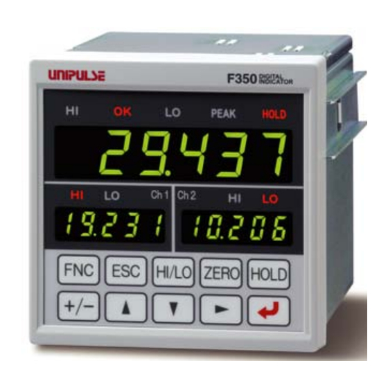
CAUTION 1 OUTLINE 1-3. About connectable devices Chapter Printer Display Various converters Strain gauge type sensor (Option) D/A Converter (Option) (Option) Valve, recorder 1-4. Appearance description ■Front panel F 350 Main status display section Main numerical display section Sub status display section Sub numerical display section... - Page 17 CAUTION 1 OUTLINE Main status display section Chapter The status with respect to calculated values is indicated. Lights when the indicated value is larger than the calculation HI limit. HI: Indicates that the external output "calculation HI" is ON. Lights when the indicated value is smaller than the calculation HI limit and larger OK:...
- Page 18 CAUTION 1 OUTLINE Setting key pad Chapter These are keys for commanding settings and operations. ・Use this key to go to a setting mode state. ・Use this key to cancel setting/execution. ・Use this key to go back from a setting mode state to an indication display state. ・Use this key to take a shortcut from an indication display state to HI/LO limit setting.
-
Page 19: Rear Panel
CAUTION 1 OUTLINE ■Rear panel Chapter Options slot Power input terminal Frame ground Signal input/output connector Analog input/output Protective ground connector Analog input/output connector Connect a strain gauge sensor or voltage output. * For connection, see "■ Analog input/output connector connection" on page 10. Signal input/output connector Connect external input/output signals or SI/F (serial interface). -
Page 20: Installation & Connection
● For connections to the signal input/output terminals, carry out wiring properly after confirming the signal names and pin assignment numbers. ● Use of the F350 is limited to category II specified by EN61010. Overvoltage applied to the signal input/output terminals should not exceed the value defined to category ●... -
Page 21: Installation
2 INSTALLATION & CONNECTION 2-1. Installation To install the F350 into a control panel, use the following procedure. Make a hole in the panel according to Chapter 92mm the panel-cut dimensions. – Panel-cut dimensions 92mm Panel thickness 0 – 1.6 to 3.2mm Remove the screws (two), and remove the guide rails from both sides. -
Page 22: Connection
2 INSTALLATION & CONNECTION 2-2. Connection ■Power input terminal connection Connect an AC input cord. The input power source is free in the range of 100 to 240V AC (-15%, Chapter +10%). The frequency is 50/60Hz. Make connections to the terminal block with a solderless terminal within 6mm in diameter as shown in the illustration so as not to let the tip of the cable spread out. -
Page 23: Analog Input/Output Connector Connection
2 INSTALLATION & CONNECTION ■Analog input/output connector connection Connect a strain gauge sensor or voltage output. Make connections according to the silk-screen printing on the rear panel of the F350. ●Pin Assignment Chapter SHIELD -MONITOR(ch2) +MONITOR(ch2) -MONITOR(ch1) +MONITOR(ch1) -SIG(ch2) +SIG(ch2) -SIG(ch1) -
Page 24: How To Connect And Install The Terminal Block
Lightly pull the wire to make sure that it is securely clamped. Tighten. (Turn clockwise.) Insert the wire-connected plug into the F350 body, and tighten the screws (two). Tighten. (Turn clockwise.) ■Attachment of a ferrite core It is necessary to twist a power supply cable and sensor cables, such as a load cell, around an attached ferrite core. -
Page 25: Strain Gauge Sensor Connection
2 INSTALLATION & CONNECTION ■Strain gauge sensor connection ■ 4-wire sensor SHIELD Chapter -SIG +SIG -OUT +OUT F350 -SIG +SIG -OUT +OUT -EXC +EXC SHIELD ■ 6-wire sensor SHIELD -SIG +OUT -OUT +SIG F350 -SIG + IN Short-circuit +EXC with +S... -
Page 26: Strain Gauge Sensor Cable Coloration
Chapter CAUTION The excitation voltage of the F350 is 2.5V/10V. If the maximum excitation voltage of the sensor is under 2.5V/10V, heating or damage may result. ■Voltage output connection The voltage output terminals output analog voltage in proportion to each sensor signal input. -
Page 27: External I/O Connection
COM2 terminal. Short-circuiting is effected by means of a contact (such as a relay or a switch) or a noncontact (such as a transistor or an open-collector TTL) Open → OFF F350 Inside +12V Short → ON TTL Open Collector... -
Page 28: How To Assemble The Connector
Be aware that washers should be set to the M2×10 pan-head machine screws (two). ■SI/F interface connection Two-wire serial interface (SI/F) for connecting printers and external display from UNIPULSE. Connect from A11 and A12 of the external input/output connector. The interface is nonpolarized and up to three external devices can be connected. -
Page 29: Setting Mode Configuration
3 SETTING MODE CONFIGURATION SETTING MODE CONFIGURATION 3-1. Setting mode composition Chapter HI/LO Indicated value HI/LO limit setting display mode (P21) PEAK HOLD PEAK HOLD PEAK HOLD Ch1 Ch 2 Ch1 Ch 2 Ch1 Ch 2 F1 ( Mode1) F2 ( Mode2) F3 (... - Page 30 3 SETTING MODE CONFIGURATION Chapter PEAK HOLD PEAK HOLD PEAK HOLD Ch1 Ch 2 Ch 2 Ch1 Ch 2 F4 ( Mode4) F5 ( Mode5) Mode F9 ( 9) Option Calibration setting Protect/initialize DAV/DAI 1: Calibration function select 1: Output data 1: Communication 1: Output data 1: Setting protect...
-
Page 31: Key Operation
3 SETTING MODE CONFIGURATION 3-2. Key operation ≪Setting procedure≫ From the indicated value display, Go back to the indicated value. "F1" of setting mode 1 is displayed on the SUB display (ch1 side). Chapter Selecting a setting mode. Go back to setting mode 1. ・... - Page 32 3 SETTING MODE CONFIGURATION ≪Setting mode select state≫ 【Setting mode 1(COP.HLD)】 【Setting mode 2(SYS.OPR)】 【Setting mode 3(SYS.ch)】 PEAK HOLD PEAK HOLD PEAK HOLD Ch1 Ch 2 Ch1 Ch 2 Ch1 Ch 2 Chapter 【Setting mode 4(CAL.)】 【Setting mode 5(OPTION)】 【Setting mode 9(PRT.INI)】 PEAK HOLD PEAK...
- Page 33 3 SETTING MODE CONFIGURATION ≪Setting item select state≫ 【Normal setting item (with separate 【Normal setting item】 settings on ch1 and ch2)】 PEAK HOLD PEAK HOLD Ch1 Ch 2 Ch1 Ch 2 Chapter Selected ch display 1 : ch1 2 : ch2 Item number (1 - 9) Mode number (1 - 5, 9) 【Calibration operation item】...
- Page 34 3 SETTING MODE CONFIGURATION ≪HI/LO limit setting mode function≫ By pressing on the indicated value display screen, you can enter a HI/LO limit setting HI/LO item select state. Press at the setting value you want to change, and you will go to a setting value input state.
-
Page 35: Calling A Setting Mode
3 SETTING MODE CONFIGURATION 3-3. Calling a setting mode Example) For changing the ch1 digital filter from "000" to "256" Press from an indicated value display state. PEAK HOLD Ch1 Ch 2 Go to a setting mode select state. Chapter PEAK HOLD Press twice to make the mode number "3."... -
Page 36: Calibration Procedure
CALIBRATION PROCEDURE 4-1. How to calibration "Calibration" refers to an operation whereby matching between the F350 and a strain gauge sensor is obtained. The F350 uses the two calibration methods as described below. ■Equivalent input calibration Calibration is performed without an actual load by entering the rated output value (mV/V) and the capacity (to be indicated) of the strain-gage sensor by the keys. -
Page 37: Procedure Of Equivalent Input Calibration And Calibration Protect
4 CALIBRATION PROCEDURE 4-2. Procedure of equivalent input calibration and calibration protect The equivalent input calibration and the calibration protect uses the following procedure : Equivalent input Actual load calibration calibration Turn off the calibration protect that inhibits ① Calibration protect calibration. - Page 38 4 CALIBRATION PROCEDURE ①Releasing the calibration protect Turn off the calibration protect that inhibits calibration. ≪Setting value≫ 0:OFF Enables rewriting of setting values. 1:ON Disables rewriting of setting values. ◇Calibration protect setting method Select setting mode 9. Ch1 Ch 2 Press five times.
- Page 39 The maximum excitation voltage value of the strain gauge sensor connected to the F350 should always be larger than the set bridge voltage. If the excitation voltage of the F350 is larger than the maximum excitation voltage value of the strain gauge sensor, the strain gauge sensor may heat or break.
- Page 40 4 CALIBRATION PROCEDURE ⑤Zero calibration Register the zero point with the sensor unloaded. Also, if there is any initial load, such as a jig, for measurements, the zero point can be registered with the initial load applied, but the signal input range needs to be considered as the initial load is subtracted from it.
- Page 41 4 CALIBRATION PROCEDURE ⑥a.Equivalent input calibration See the test report of the sensor, and register the rated output value and the value you want to display at that time (rated capacity value). Input the rated output value and display value (rated capacity value) successively. Equivalent input calibration is not executed by simply inputting the rated output value.
- Page 42 4 CALIBRATION PROCEDURE Equivalent input calibration is executed. PEAK PEAK HOLD HOLD A message as shown on the right-hand side is displayed. If equivalent input calibration is not executed normally, Ch1 Ch 2 Ch1 Ch 2 the alarm sounds. If equivalent input calibration is executed normally, PEAK HOLD you will go back to the setting item select state.
- Page 43 4 CALIBRATION PROCEDURE ⑥b.Actual load calibration Apply an actual load, and register the value of the actual load (rated capacity value). ≪Setting value≫ -19999~19999 (except 0) By performing actual load calibration, the setting value of equivalent input calibration becomes the sensor output value (mV/V) of the time when it was executed. The load with which actual load calibration was performed can be confirmed.
- Page 44 4 CALIBRATION PROCEDURE ⑦Digital offset This function is to subtract a set value from the indicated value. This function is convenient when zero cannot be obtained with no load for some reason or for offsetting. When not using, set "0." (Displayed value)=(Actual indicated value)-(Setting value of digital offset) ≪Setting value≫...
- Page 45 4 CALIBRATION PROCEDURE ⑧Digital Zero limit Set the load limit that allows Digital Zero. If the absolute value of the load at which Digital Zero is about to be performed is larger than the setting value, an error will result, and the indicated value will not be zeroed. ≪Setting value≫...
- Page 46 4 CALIBRATION PROCEDURE ⑨Alarm HI and LO limits Overload of the ch1 value and ch2 value is monitored. When they exceed the alarm HI limit or fall below the alarm LO limit, the external output "ALM" turns ON. Alarm HI limit: -19999 ~...
- Page 47 4 CALIBRATION PROCEDURE ⑩Locking the calibration protect Turn on the calibration protect that inhibits calibration. ≪Setting value≫ 0:OFF Enables rewriting of setting values. 1:ON Disables rewriting of setting values. ◇Calibration protect setting method Select setting mode 9. Ch1 Ch 2 Press →...
-
Page 48: Explanation Of Indicated-Value-Related Functions
5 EXPLANATION OF INDICATED- VALUE-RELATED FUNCTIONS EXPLANATION OF INDICATED- VALUE-RELATED FUNCTIONS 5-1. A/D conversion speed select The A/D conversion speed can be selected from 300 times/sec. or 3000 times/sec. ≪Setting value≫ 0:300 times/sec. 1:3000 times/sec. If the A/D conversion speed is changed, the processing shown below will follow it. ●... -
Page 49: Analog Filter
5 EXPLANATION OF INDICATED- VALUE-RELATED FUNCTIONS 5-2. Analog filter This is a low-pass filter for filtering input signals from the strain gauge sensor, and canceling unwanted noise components (a filter that passes only the signals with a specific frequency or less, and attenuates signals with higher frequencies). -
Page 50: Digital Filter
5 EXPLANATION OF INDICATED- VALUE-RELATED FUNCTIONS 5-3. Digital filter The digital filter is a function for reducing fluctuations of the indicated value by means of a moving average of data converted from analog to digital. With an increase in the number of filterings, the indicated value becomes more stable, but the response to inputs becomes slower. -
Page 51: Digital Zero
5 EXPLANATION OF INDICATED- VALUE-RELATED FUNCTIONS 5-4. Digital Zero This function is to zero the indicated value. ■Digital Zero / Digital Zero reset by means of keys Digital Zero can be executed for the ch1 value and ch2 value individually or at one time. Digital Zero reset can also be executed. -
Page 52: Digital Zero By Means Of The External Signal "D/Z Input
5 EXPLANATION OF INDICATED- VALUE-RELATED FUNCTIONS ■Digital Zero by means of the external signal "D/Z input" The instant when D/Z and COM2 of the input/output connector are short-circuited from an open state (ON edge), Digital Zero functions to zero both the ch1 value and ch2 value at one time. Keep ON for 1.0 msec or more. -
Page 53: Zero Tracking
5 EXPLANATION OF INDICATED- VALUE-RELATED FUNCTIONS 5-6. Zero Tracking This function is to automatically track and correct gradual changes in the zero point due to drifts (phenomenon in which outputs fluctuate slowly due to temperature change or change with time), etc. ≪Setting value≫... -
Page 54: Motion Detect
5 EXPLANATION OF INDICATED- VALUE-RELATED FUNCTIONS ・When displacement of the zero point is within the set count of tracking and it continues more than the set time, it is automatically made zero by Zero Tracking function. ・The time (tracking delay) is set in the range of 0.1 - 9.9 sec., and the band (tracking band) is set in the range of 01 to 99. -
Page 55: Motion Detect Setting Method
5 EXPLANATION OF INDICATED- VALUE-RELATED FUNCTIONS Setting example Motion Detect (time) 0.4 sec. Motion Detect (range) Indicated value Motion Detect time ( 0.4sec.) dn = 50msec. difference of the previous instruction value Time 50msec. Chapter When the condition of dn ≦ set count (10) continues for the set time (0.4 sec.) or more (d1 ≦... -
Page 56: Display Frequency
5 EXPLANATION OF INDICATED- VALUE-RELATED FUNCTIONS 5-8. Display frequency Set the per-second display update frequency of the indicated value. However, the A/D conversion speed does not change. ≪Setting value≫ 3 times 6 times 2: 13 times 3: 25 times ■Display frequency setting method Select setting mode 2. -
Page 57: Explanation Of Comparison Functions
6 EXPLANATION OF COMPARISON FUNCTIONS EXPLANATION OF COMPARISON FUNCTIONS 6-1. Calculation mode Set the calculation method for the ch1 value and ch2 value. 0:ch1+ch2 The ch2 value is added to the ch1 value. 1:ch1-ch2 The ch2 value is subtracted from the ch1 value. 2:|ch1-ch2| The absolute value of the difference between the ch1 value and ch2 value is calculated. -
Page 58: Hi/Lo Limit Comparison Of Calculated Value / Ch1 Value / Ch2 Value
6 EXPLANATION OF COMPARISON FUNCTIONS 6-2. HI/LO limit comparison of calculated value / ch1 value / ch2 value Set the HI/LO limit of calculated value/ch1 value/ch2 value. Calculated value -99999 ~ 99999 Ch1 value / ch2 value -19999 ~ 19999 <HI/LO output conditions> Indicated value >... -
Page 59: Hysteresis Setting Method
6 EXPLANATION OF COMPARISON FUNCTIONS ・LO ON conditions Indicated value < LO limit OFF conditions Indicated value ≧ (LO limit setting value-Hysteresis setting value) ・Hysteresis operation Indicated value High limit value Hysteresis range Low limit value + Time - HI output HI status display Output OFF Output ON... -
Page 60: Near Zero
6 EXPLANATION OF COMPARISON FUNCTIONS 6-4. Near Zero This function is to detect that the indicated value (calculated value) is Near Zero. Near Zero ON: |Calculated value| ≦ Setting value of Near Zero Near Zero OFFF: |Calculated value| > Setting value of Near Zero ≪Setting value≫... -
Page 61: Calculation Comparison Timing
6 EXPLANATION OF COMPARISON FUNCTIONS 6-5. Calculation comparison timing Set the operating conditions of calculation HI/LO limit comparison. Select the conditions from the following. 0:All time HI/LO limit comparison is always performed. 1:Stable HI/LO limit comparison is performed when the calculated value is stable. -
Page 62: Comparison Ok Output Conditions
6 EXPLANATION OF COMPARISON FUNCTIONS 6-6. Comparison OK output conditions Conditions to turn on the external output "Calculation OK output" can be set. 0:Calculated value only The output turns on when calculation HI limit/LO limit is off. 1: Calculated value & ch1 The output turns on when calculation HI limit/LO limit and ch1 HI limit/LO limit are all off. -
Page 63: Explanation Of Hold Functions
7 EXPLANATION OF HOLD FUNCTIONS EXPLANATION OF HOLD FUNCTIONS 7-1. Hold functions of calculated values The hold functions are to take out a specific point of calculated values for HI/LO limit comparison. Here, the operation of each hold will be described in detail. Hold mode Hold section None... -
Page 64: Setting Of Hold Mode
7 EXPLANATION OF HOLD FUNCTIONS 7-2. Setting of hold mode ■ Hold mode setting method Select setting mode 1. Ch1 Ch 2 Press once. Set " ." Hold mode PEAK HOLD Press four times ⇒ "Calculation hold function select " is displayed. Ch1 Ch 2 Press , and the highest digit blinks. -
Page 65: Peak Hold
7 EXPLANATION OF HOLD FUNCTIONS ■Peak hold The maximum value in the positive direction (peak value) of the specified section is held. The section is specified by the setting of "all section," "external signal," or "external signal + time." (Example) Externally specified section peak hold t1: A delay time between the instant +... -
Page 66: Average Hold
7 EXPLANATION OF HOLD FUNCTIONS ■Average hold The average of the sampling values over the specified section is calculated and updated, and then held. The section is specified by the setting of "all section," "external signal," or "external signal + time." (Example) Externally specified section average value hold t1: A delay time between the instant when the SECTION signal is inputted... -
Page 67: Setting Of Hold Section
7 EXPLANATION OF HOLD FUNCTIONS ◇Average sample number setting method Select setting mode 1. Ch1 Ch 2 Press once. Set "Average sample number." PEAK HOLD Press six times ⇒ "Average sample number " is displayed. Ch1 Ch 2 Press , and the highest digit blinks. Input the setting value with . ... -
Page 68: All Section
7 EXPLANATION OF HOLD FUNCTIONS ■All section By this method, the hold detection section is specified by the T/H signal. Detection starts with the T/H signal ON to perform each hold operation. Control is performed simply by the T/H signal without using the SECTION signal. Therefore, there are tracking sections and detection sections, but there are no hold deciding sections. -
Page 69: External Signal
7 EXPLANATION OF HOLD FUNCTIONS ■External signal By this method, the hold detection section is specified by the SECTION signal. Detection starts with the SECTION signal ON, and ends with the SECTION signal OFF to perform each hold operation. The hold value is maintained until the hold reset signal is turned on. The hold is released by turning on the T/H signal as a reset signal. -
Page 70: External Signal + Time
7 EXPLANATION OF HOLD FUNCTIONS ■External signal + time By this method, the hold detection section is specified as a timer. Detection starts with the SECTION signal ON, and ends when the set time (detection time) has elapsed. The hold value is maintained until the hold reset signal is turned on. The hold is released by turning on the T/H signal as a reset signal. -
Page 71: Auto Reset Function
7 EXPLANATION OF HOLD FUNCTIONS 7-4. Auto reset function It is factory-set that each hold is automatically reset at the start of the detection section, and therefore, simple control can be performed by one signal without releasing the hold. Example) Auto reset in externally specified section peak hold SECTION Upon turning-ON of the SECTION signal, Control can be performed without inputting the T/H... -
Page 72: Auto Reset Setting Method
7 EXPLANATION OF HOLD FUNCTIONS ■Auto reset setting method Select setting mode 1. Ch1 Ch 2 Press once. Set "Auto reset." PEAK HOLD Press four times ⇒ "Calculation hold function select " is displayed. Ch1 Ch 2 Press , and the highest digit blinks. Press three times to make the digit of 《Setting value》... -
Page 73: Standard Interface
8 STANDARD INTERFACE STANDARD INTERFACE 8-1. External I/O ■Connector pin assignment COM1 COM1 HI(Calculated) ALM(ch2) OK(Calculated) LO(Calculated) HI(ch1) LO(ch1) COM1 COM2 ALM(ch1) SECTION HI(ch2) LO(ch2) SI/F D/Z-1 SI/F D/Z-2 Compatible connector: FCN-361J024-AU(manufactured by FUJITSU COMPONENT or equivalent) Connector cover: FCN-360C024-B(manufactured by FUJITSU COMPONENT or equivalent) (connector &... -
Page 74: About Inputs
8 STANDARD INTERFACE 2-wire serial interface for connecting a → " ■ SI/F interface connection " on page 15 A11, A12 UNIPULSE-manufactured printer, external "8-2 SI/F(Serial interface) " on page 62 display, etc. ■About inputs Common for external input signals. →... -
Page 75: Si/F(Serial Interface
8 STANDARD INTERFACE 8-2. SI/F(Serial interface) ■SI/F Indicated value format For the SI/F, indicated value data exist in two areas: GROSS area and NET area. Select the data. 《Setting value》 0:Calculated value/ch1 value GROSS area:calculated value NET area:ch1 value 1:Calculated value/ch2 value GROSS area: calculated value NET area: ch2 value 2:ch1 value/ch2 value... - Page 76 8 STANDARD INTERFACE Point When stable value print is selected, be aware that automatic printing is not performed in the following case. ・When Motion Detect is set in time: 0.0 sec, count: 00. Also, the indicated value is not held in the following case. ・Hold mode:...
-
Page 77: Option Interface
9-1. BCD interface The BCD data output is an interface to extract the indicated value of the F350 as BCD data. This interface is convenient to process controls, totals, records, etc., by connecting the F350 to a computer, process controller, sequencer or the like. -
Page 78: Connector Pin Assignment
9 OPTION INTERFACE ●Input F350 Transistor Inside Outside IC=Approx.6mA Switch TTL open collector output (ON when IN is HI) Open Short CAUTION ● Do not apply external voltage to the signal input circuit. ● The external element is required to withstand Ic=10mA. -
Page 79: Output Data Select
9 OPTION INTERFACE ■Output data select 《Setting value》 0:Calculated value The calculated value is output. 1:ch1 value The ch1 value is output. 2:ch2 value The ch2 value is output. 3:External select Data selected by the data select input (A15, B15) is output. Data select 1 Data select 0 Output data... -
Page 80: Logic Switching
9 OPTION INTERFACE Update BCD data STAB OVER STROBE Strobe range (duty 50%) ■Logic switching Select the logic of the BCD data output signal. Make selection with B14. When COM and B14 are open :Negative logic When COM and B14 are short-circuited :Positive logic Read at least 2 cycles after inputting the logic switching. -
Page 81: Output Rate
9 OPTION INTERFACE ■Output rate 《Setting value》 0:10 4:300 1:30 5:500 2:50 6:1000 3:100 【times/sec.】 * When the A/D conversion speed is 300 times/sec., settings are available up to 4: 300 [times/sec.]. Point Even if this setting is changed, A/D conversions speed does not change. Make the output rate slower when reading fails due to a low processing performance of the device that should receive BCD. -
Page 82: Pin Assignment At Binary
9 OPTION INTERFACE ◇BCD/binary setting method Select setting mode 5. Ch 2 Press four times. → Select "BCD/binary select." PEAK HOLD Press three times. ⇒ "BCD/binary select" is displayed. Ch1 Ch 2 Press , and present set value blinks. Input the setting value with (Initial value:0)... -
Page 83: Rs-232C Interface
9-2. RS-232C interface The RS-232C is an interface to read the indicated value and status of the F350 and to write parameters into the F350. This interface is convenient to process controls, totals, records, etc., by connecting the F350 to a computer, process controller, sequencer or the like. -
Page 84: Connection
2:Print send mode When the indicated value is printed (a print command is output to the SI/F), the Chapter indicated value and status are sent from the F350 to host. ◇Communication mode setting method Select setting mode 5. Ch 2 Press →... -
Page 85: Communication Conditions
Character length 0 : 7bit 1 : 8bit Baud rate 0 : 9600 bps 2 : 38400 bps 1 : 19200 bps 3 : 57600 bps ■Delimiter Set the delimiter for sending messages from the F350. 《Setting value》 0:CR Chapter 1:CR+LF ◇Delimiter setting method Select setting mode 5. -
Page 86: Communication Format
9 OPTION INTERFACE ■Communication format 1.Send/receive [Reading the indicated value/status] Reading the indicated value/status Header Function Protocol Main R A Host Indicated value F350 R A Delimiter (Calculated value) Sign, decimal point, 5-digit indicated value. R B Host F350 Indicated value R... - Page 87 9 OPTION INTERFACE Reading the indicated value/status Header Function Protocol Main R F Host F350 R F Delimiter -LOAD (ch1) 0 : OFF 1 : ON Status 3 +LOAD (ch1) 0 : OFF 1 : ON (ch1) OFL1 ( ch1) 0 : OFF 1 : ON OFL2 (...
- Page 88 9 OPTION INTERFACE 2. Send/receive [Setting value writing/reading] Channel selection (Setting value with channel switching) Header Function Protocol Main Host F350 channel 1 : ch1 2 : ch2 command 0 fixation - switching 00 fixation * For a setting value with ch switching, make sure to write in advance the channel number selected, and then write or read the setting value.
- Page 89 9 OPTION INTERFACE 3. Send/receive[Command] Movement directive Header Function Protocol Main Zero calibration (with channel Host switching) F350 Equivalent input calibration Host (with channel F350 switching) Digital Zero (simultaneous on both Host channels) F350 Digital Zero reset (simultaneous on both Host...
-
Page 90: Continuousness / Print Send Mode
Protocol Main * Delimiter Host F350 1: The command or message length is improper. 2: The protect of the setting value you are going to write Error occurrence is ON, or a calibration command is received while the (send/receive mode) calibration protect is ON. -
Page 91: D/A Converter Output
A D/A converter is provided for obtaining analog output synchronized with the indicated value of the F350.The analog output ranges are -10 - +10V output and 4 - 20mA constant-current output. By using the D/A zero setting and D/A full scale setting functions, analog output can be obtained between zero (0V, 4mA) and full scale (10V, 20mA) with respect to the predetermined digital value. -
Page 92: Output Data Select
9 OPTION INTERFACE Connecting to cage clamp terminal block Strip the casing 0.2in (6mm) on the cable to be 5 ~ 6mm connected. Twist the bare wire to fit the terminal hole. Insert the supplied screwdriver into the upper hole and lift upward. Insert the twisted wires into the lower hole. -
Page 93: Zero/Full Scale Setting
9 OPTION INTERFACE ◇ Output data select setting method Select setting mode 5. Ch 2 Press four times. → Set "Output data select." PEAK HOLD Press once. ⇒ "Output data select" is displayed. Ch1 Ch 2 Press , and present set value blinks. Input the setting value with (Initial value:0)... -
Page 94: Adjustment By Fixed Output
9 OPTION INTERFACE ② Set "Full scale value." PEAK HOLD Press once. ⇒ "Full scale value" is displayed. Ch1 Ch 2 Press , and the highest digit blinks. Input the setting value with , and move to the lower digit with * For inputting a negative sign, press Press to validate it. -
Page 95: Specifications
10 SPECIFICATIONS SPECIFICATIONS 10-1. Specifications ■Analog section Number of sensor inputs 2 inputs Sensor excitation DC10V、2.5V±5%(It depends on the setting.) Output current:Within 60mA (2 channels total) * The following are common to each input. Signal input range -3.0~+3.0mV/V Accuracy Non-linearity: Within 0.02%FS±1 digit (at a 3.0mV/V input) Zero drift:... -
Page 96: External Input/Output Section
(internal circuit power supply voltage 12V) External output Open collector output circuit (sink type) for comparison output, etc. Rated voltage: 30V, driving current: 30mA or less ■Interface 2-wire serial interface for connecting a UNIPULSE-manufactured printer, external display, etc. Transmitting method: Asynchronous Baud rate: 600bps Output data:... -
Page 97: General Performance
10 SPECIFICATIONS D/A converter current output (DAI) Output range: 4 to 20mA Load resistance: 350Ω or less D/A conversion speed: Follows the original A/D conversion speed Resolution: 1/10000 Zero/span adjustment range:±10%F.S. Non-linearity: ±0.05%F.S. Output data: Selected by the setting of "calculated value,"... -
Page 98: 10-2.Dimensions
10 SPECIFICATIONS 10-2. Dimensions ■Standard equipment Unit: mm ■Equipped with BCD parallel data output interface option Unit: mm Chapter... -
Page 99: Equipped With Rs-232C Interface Option
10 SPECIFICATIONS ■Equipped with RS-232C interface option Unit: mm ■Equipped with D/A converter option Unit: mm Chapter... -
Page 100: F350 Block Diagram
10 SPECIFICATIONS 10-3. F350 block diagram FRAME MONITOR1 SHIELD Buffer + SIG Gain Low-pass Conversion ×100 Fillter adjustment 24bit - SIG Excitation + EXC Base Voltage Voltage 2.5,10V - EXC + SIG Gain Low-pass Conversion ×100 Fillter adjustment 24bit MONITOR2 - SIG... -
Page 101: 11Supplements
11 SUPPLEMENTS SUPPLEMENTS 11-1. The list of initial setting value * Initial value Factory default value * Setting by ch With ch1/ch2 switching ◎: No mark: One setting only * Operation ○: Functions on calculation only ◎: Functions on ch1/ch2 No mark: Functions generally }... - Page 102 11 SUPPLEMENTS ■Mode 1; work setting (comparison/hold) PEAK HOLD Setting item Initial Opera Protec Refer Setting Setting range value by ch tion ence Name Undefined Undefined Calculation comparison OK output condition 0: Calculated value OK only 1: Calculated value OK & ch1 value OK 2: Calculated value OK &...
- Page 103 11 SUPPLEMENTS ■Mode 2; system setting (calculation/common operation) PEAK HOLD Setting item Initial Opera Protec Refere Setting Setting range value by ch tion Name Motion Detect 0.0-00 ○ ◎ ◎ Range Times 00 ~ 99 【 count】 0.0 ~ 9.9 【sec.】 Undefined SI/F Indicated value format 0: Calculated value/ch1...
- Page 104 11 SUPPLEMENTS ■Mode 4; calibration setting (ch calibration) PEAK HOLD Setting item Initial Opera Protec Refere Setting Setting range value by ch tion Name Min. scale division 0 : 1 1 : 2 Decimal place 2 : 5 0 : None 3 :...
- Page 105 11 SUPPLEMENTS ■Mode 5; system setting (232 option) PEAK HOLD Setting item Initial Opera Protec Refere Setting Setting range value by ch tion Name 0 : Send/receive Communication mode 1 : Continuous send ◎ ◎ 2 : Print send Flow control 0: None 1 :...
- Page 106 11 SUPPLEMENTS ■Mode 9; protect/initialize PEAK HOLD Setting item Initial Opera Protec Refere Setting Setting range value by ch tion Name Calibration protect 0 : OFF 1 : ON Setting protect System protect ◎ 0 : OFF 1 : ON Work protect 0 :...
-
Page 107: 11-2.Self-Check Function
This function is not to diagnose the analog circuit. ■Self-check method Turn off the power of the F350. Turn on the power while pressing If "PASS" is displayed at the end, it is normal. -
Page 108: 11-3.Setting Protect
11 SUPPLEMENTS 11-3. Setting protect Each category of setting values can be locked to prevent rewriting. For each category, see the setting value list. 0:OFF Enables rewriting of setting values. 1:ON Disables rewriting of setting values. ≪Setting value≫ 0 0 0 Calibration protect 0 :... -
Page 109: 11-4.Key Protect
11 SUPPLEMENTS 11-4. Key protect key and key operations are disabled to prevent misoperation. ZERO HOLD 0:OFF Enables key operations. 1:ON Disables key operations. ≪Setting value≫ 0 0 0 Undefined HOLD Key protect 0 : OFF 1 : ON ZERO Key protect 0 :... -
Page 110: 11-5.Initialize
11 SUPPLEMENTS 11-5. Initialize Each category of setting values can be initialized. For each category, see the setting value list. ≪Setting value≫ (0:Undefined) 1:Work setting 2: System setting (Including setting protect and key protect) 3:Calibration setting After inputting the number of the setting value category you want to initialize, press validate it, and initialization is executed. -
Page 111: Sub Numerical Display Section
11 SUPPLEMENTS ■Sub numerical display section -LoAd Beyond the signal input The input electric signal greatly exceeds the signal range -3.2mV/V input range. This also occurs when an excessive load is applied to the sensor or the input terminal is opened LoAd Beyond the signal input due to a break in the cabling, etc. -
Page 112: 11-8.Troubleshooting
Item Question Answer/remedy In the F350, the excitation voltage is shared by 2 channels. There is a need to use it in a range of output current that the Can four sensors be 2 channels total does not exceed 60mA. For example, one connected? 350Ω... - Page 113 F350. GROSS area and NET abnormal. area exist. Check that the areas and setting correspond. SI/F Check to see if the SI/F print setting of the F350 is correct. Check the setting. Automatic printing cannot be performed.
- Page 114 11 SUPPLEMENTS 11-9. About disposal of the lithium battery When disposing of the F350, make sure to remove the lithium battery and collect it separately. Also, after power-off, take sufficient time to discharge the internal capacitor. ■Removal of the lithium battery Disconnect all cables.
Need help?
Do you have a question about the F350 and is the answer not in the manual?
Questions and answers