Unipulse F381A Operation Manual
Dynamic force processor
Hide thumbs
Also See for F381A:
- Operation manual (55 pages) ,
- Operation manual (29 pages) ,
- Operation manual (59 pages)
Table of Contents
Advertisement
Quick Links
Advertisement
Table of Contents

Related Manuals for Unipulse F381A


Summary of Contents for Unipulse F381A
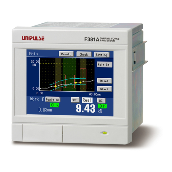
- Page 1 F381A DYNAMIC FORCE PROCESSOR OPERATION MANUAL 15APR2013REV.3.10...
-
Page 2: Safety Precautions
For good performance, and proper and safe use of the F381A, be sure to read this instruction manual and properly understand the contents of it before use. Also, carefully keep this instruction manual so that it can be referred to at any time. - Page 3 Warning on design ● For the entire system to function safely when the F381A becomes faulty or malfunctions, provide a safety circuit outside the F381A. Warning on installation ● Do not modify the F381A. Doing so may cause fire or electric shocks.
- Page 4 - Do not wipe with a wet rag, or with benzine, thinner, alcohol, etc. Doing so may cause discoloration or deformation of the F381A. In the case of heavy contamination, wipe off the contamination with a cloth after dipping it into a diluted neutral detergent and wringing it well, and then wipe with a soft, dry cloth.
- Page 5 About the Built-in Lithium Battery About the Built-in Lithium Battery About the Built-in Lithium Battery This sign forewarns the presence of hazards WARNING that could result in serious injury or fatality when incorrectly handled. ● Never disassemble, deform under pressure or throw the battery into fire.The battery may explode, catch fire or leak.
-
Page 6: Table Of Contents
Contents Contents Contents 1 OUTLINE ........... . . 1 1-1. - Page 7 Contents Contents 4-3. X-axis setting ............42 4-4.
- Page 8 Contents Contents ■Cautions............. 119 6 SYSTEM SETTINGS .
- Page 9 Contents Contents M E M O VIII VIII...
-
Page 10: Outline
1-2. Features The F381A is a Dynamic Force Processor that can display waveforms of physical quantities, such as load, pressure, torque, etc., in combination with a strain gauge type sensor. Changes in physical quantities that are hard to grasp numerically can be grasped visually on waveform display. - Page 11 1 OUTLINE ● Drawing of load-time and load-displacement waveforms Not only a load-time waveform in connection with a load sensor but also a load-displacement Chapter waveform can be drawn in combination with a load sensor and displacement sensor. < In case of time > <...
- Page 12 1 OUTLINE ● Control of the position at the measurement completion The position of the measurement completion can be judged by using the End Displacement for Chapter the Use Hold. The End Displacement is different from other hold types, so it judges not based on a wave starting point but based on an original point of the displacement.
- Page 13 1 OUTLINE respectively, as “Waveform Reference.” Normally use “Front,” but use “Back” if the displacement for insertion work is applied. Chapter * In case of “Front”, the waveform of which 0mm is the measurement start point is displayed. In case of “Back”, the waveform of which 0mm is the measurement stop point is displayed. Measurement waveform Comparison waveform <...
-
Page 14: About Connectable Devices
1 OUTLINE - Measurement Stop Condition Chapter < Forced-Stop > < Forced-Stop > (maximum data acquisition) (external input) Load Load Measurement Measurement Section Section Maximum data 2048 points Time or Time or displacement displacement Stop < Load > < Time > Load Load Measurement... -
Page 15: Part Names And Functions
1 OUTLINE 1-4. Part names and functions Chapter ■Front panel Liquid crystal touch panel display Power lamp SD card slot cover Liquid crystal touch panel display Indicated values and graphs are displayed, and various items are set on this liquid crystal touch panel display. -
Page 16: Rear Panel
1 OUTLINE ■Rear panel Chapter RS-232C connector DC power input terminal block Control connector Frame ground Protective ground Option board mounting slot Analog input/output connector DC power input terminal block Connect the DC power cord. The power supply voltage is 24V DC (±15%). Frame ground (functional ground) F.G. -
Page 17: Terms
1 OUTLINE 1-5. Terms Chapter Terms used in this manual are explained below. - Load Analog and digital values of load sensor input are expressed as load. - Displacement Analog and digital values of displacement sensor input are expressed as displacement. - Waveform comparison Checking to see if the acquired waveform is between the HI limit and LO limit waveforms having been prepared in advance is called waveform comparison. -
Page 18: Installation And Connection
2 INSTALLATION AND CONNECTION INSTALLATION AND CONNECTION 2-1. Installation Chapter To install the F381A into a control panel, use the following procedure. Make a hole in the panel according to the 92mm 0 – panel-cut dimensions. Panel-cut dimensions 92mm 0 –... -
Page 19: Sensor Connection
Loosen the screws (two) with a screwdriver. Loosen. (Turn counterclockwise.) Remove the terminal block by giving it a strong pull. Loosen. (Turn counterclockwise.) Attention Insert side When installing the terminal block to the F381A body, check its orientation. (See the illustration at the right.) Right side... - Page 20 2 INSTALLATION AND CONNECTION Analog input/output terminal pin assignments - Standard (Displacement input: Pulse input (open collector)) Type Pin No. Signal Terminal to supply the voltage of the strain gauge type sensor. +EXC Connect +IN of the strain gauge type sensor. Chapter Terminal to input the signal of the strain gauge type sensor.
- Page 21 2 INSTALLATION AND CONNECTION - Option (Displacement input: Pulse input (line driver) [LDI]) Type Pin No. Signal Terminal to supply the voltage of the strain gauge type sensor. +EXC Connect +IN of the strain gauge type sensor. Terminal to input the signal of the strain gauge type sensor. -SIG Connect –OUT of the strain gauge type sensor.
-
Page 22: Load Sensor Connection
+SIG +SIG F.G. F.G. CAUTION The excitation voltage of the F381A is 2.5V/10V. If the maximum excitation voltage of the sensor is under 2.5V/10V, heating or damage may result. ■Displacement sensor connection (standard) - Input equivalent circuit An open collector output type sensor (Incremental type) can be connected. -
Page 23: Displacement Sensor Connection (When The Voltage Input Option Is Mounted)
F381A Chapter Inside Outside F.G. Voltage output F381A body type sensor Output within ±5V * Please wire for the power supply of the sensor separately. ■Displacement sensor connection (when the line driver input option is mounted) It can be connected with Line driver output-type sensor (Incremental type) in accordance with RS- 422 like the contact-type, eddy current-type or laser-type etc. -
Page 24: External Control Equipment Connection
(Standard: sink type, ISC: source type) Chapter ■External output equivalent circuits and example connections - In case of minus common connection (Standard: sink type) F381A PLC, etc. Sink type Plus common connection (Minus common connection) -
Page 25: External Input Equivalent Circuits And Example Connections
2 INSTALLATION AND CONNECTION ■External input equivalent circuits and example connections - In case of plus common connection When you connect the relay and the switch, etc. F381A Plus common connection Push Toggle Chapter A1 to A8 Switch Switch Relay Input B1 to B8 Approx. -
Page 26: Connector Pin Assignments
2 INSTALLATION AND CONNECTION Attention Connect elements that can pass Ic=5mA or more. The leak current of the elements connected should be 400μA or less. Chapter ■Connector pin assignments The adaptable connector Connector: FCN-361J040-AU (attachments) Cover: FCN-360C040-B (attachments) Load Digital Zero Work 1 DPM Positioning Work 2... -
Page 27: How To Assemble The Connector
2 INSTALLATION AND CONNECTION ■How to assemble the connector Nut M2 (four) Pan-head machine screw Pan-head machine screw M2 × 10 (long) (two) M2 × 8 (short) (two) Washer (two) Chapter Case (two) Connector Screw (two) Set the connector and screws (two) into the grooves of the case (one side). Cover with the other case, and fit the cases. - Page 28 2 INSTALLATION AND CONNECTION Result, Wave Result, Complete, Load OK, and DPM OK outputs are turned OFF. By turning the signal from ON to OFF, a “Wait Lv.” State is brought about, or the measurement is started according to the Measurement Start Condition. - Stop Stop input It should normally be wired.
- Page 29 2 INSTALLATION AND CONNECTION Output signals - Hold Result (Load/DPM) It should be wired according to application. Use it for acquiring judgment results by using the hold function. If displacement needs to be judged, also use DPM. It is not used if the hold function is not used.
- Page 30 2 INSTALLATION AND CONNECTION - SD OK It should be wired according to application. Normally use it if the SD card slot option is used. It turns OFF with a memory card error* , or when the measurement start input OFF→ON is ignored because a measurement waveform is not saved in time while being saved automatically* .
-
Page 31: How To Check Wiring
Output Press the output signal key, and check that there is input to the connected equipment. (Pressing the key turns ON the output.) Input Turn ON the output of the connected equipment. The pin recognized by the F381A turns yellow. -
Page 32: Rs-232C Connection
2 INSTALLATION AND CONNECTION 2-4. RS-232C Connection ■Connector Pin Assignment The adaptable connector is manufactured by Hosiden Corporation TCP8080-015267 or equivalent. Wire connection surface Chapter Pin No. Signal name Metal case Plastic cover Fit the metal cases into the Din connector, and cap with the plastic covers. -
Page 33: Power-On
Transmit any statement from the equipment connected. (Check only when the Communication Mode is Normal.) The data received by the F381A is displayed. Check that the transmitted data is displayed. If the Parity or Frame lights in red and the data is not displayed properly, go back to Step 1 or 2, and check again the cable or communication settings. - Page 34 2 INSTALLATION AND CONNECTION M E M O Chapter...
-
Page 35: Screens And Operations
3 SCREENS AND OPERATIONS SCREENS AND OPERATIONS 3-1. Screen configuration Main screen Setting Chapter Check Result Main Main Result screen Wave Check screen * The previously displayed screen appears. Display (The default is [Result (Single)].) Display Setting screen Each setting Set value input screen... - Page 36 3 SCREENS AND OPERATIONS Chapter Main Setting screen First Setting Work Setting Item group screen Main Each setting Each setting item screen Main Each setting Set value input screen...
-
Page 37: Explanation Of Each Screen And Key Operations
3 SCREENS AND OPERATIONS 3-2. Explanation of each screen and key operations ■Main screen Status display Reset key Measurement waveform Start/Stop key display area Digital Zero key Work display Result display(Load) Chapter Indicated value display Indicated value display(Load) (Displacement) DPM positioning key Selected indicated value display Result display(Displacement) Indicated value display selection key... - Page 38 3 SCREENS AND OPERATIONS Result display : The result is displayed. The waveform comparison and the hold results of each section are displayed overall according to the priority. * The displacement result is not displayed if X axis is time. Priority Result Judgment condition HI/LO limit over (HI limit over and LO limit over)
-
Page 39: Comparison Result Screen
3 SCREENS AND OPERATIONS : Simply makes the same movement as the Stop signal. This key is valid when the status display is Wait Lv. or Sampling. When pressed, it changes to : Simply makes the same movement as the DPM Positioning signal. However, it cannot be operated when the X-axis represents time. - Page 40 3 SCREENS AND OPERATIONS The order of priority is as follows: H/L > H,L > NG > OK SCT.1~5: Displays the Y-axis (load) and X-axis (displacement or time) values of the judgment point of each section and judgment results. Wave: Displays the Y-axis (load) and X-axis (displacement or time) values of the point at which the upper/lower limit comparison waveform is first exceeded, and the Y-axis (load) judgment result.
- Page 41 3 SCREENS AND OPERATIONS Comprehensive judgment: Displays the judgments (Y-axis and X-axis) of each section and the judgments of waveform comparisons overall. The order of priority is as follows: H/L > H,L > NG > OK Work No.: Displays the work No. used for measurement. SECT.1~5:...
-
Page 42: Wave Check Screen
3 SCREENS AND OPERATIONS ■Wave Check screen Waveform display Section display Chapter Cursor readings Display change Display range Display Cursor readings: Display the cursor-positioned load and displacement (time). Also, the HI and LO limits of comparison waveforms and the HI and LO limits of the currently-cursor-positioned section are displayed on waveform display and section display, respectively. - Page 43 3 SCREENS AND OPERATIONS - About the waveform display Reference Point Comparison of Relative Comparison waveform (HI limit) Waveform comparison judgment point Comparison waveform (LO limit) Compare Area Chapter Comparison waveform (HI limit) Comparison waveform (LO limit) Outside the Compare Area Compare Area Outside the Compare Area Comparison waveforms (HI and LO limits):...
-
Page 44: Setting Screen
3 SCREENS AND OPERATIONS Load/displacement HI and LO limits: HI limit of load The HI and LO limits of each section are indicated LO limit of load by red lines. LO limit of HI limit of displacement displacement The measurement waveform display area on the Main screen is as follows: =... -
Page 45: Item Group Screen
3 SCREENS AND OPERATIONS ■Item group screen First Setting Work Setting Chapter Parameter protection display Each group Each group Display First Protect: Displays whether parameters can be changed or not. Select by System Setting. Work Protect: Displays whether parameters can be changed or not. Select by System Setting. Keys Moves to the Main screen. -
Page 46: Each Setting Item Screen
3 SCREENS AND OPERATIONS ■Each setting item screen Normal display screen Each setting item Chapter Setting order display screen Order display Page change Page display Each setting item Display Page display: Displays the page number/total number of pages when there are two or more pages of setting items. -
Page 47: Set Value Input Screen
3 SCREENS AND OPERATIONS ■Set value input screen Numeric keypad input screen 1 Numeric keypad input screen 2 (one input item) (two input items) Numeric display Numeric keypad Chapter Selective input screen (no grouping) Selective input screen (grouped) Selective items Selection keys Graph input Selection keys Setting method display... -
Page 48: Settings And Calibrations
4 SETTINGS AND CALIBRATIONS SETTINGS AND CALIBRATIONS 4-1. Release of parameter protection To change set values, release their respective locks. Chapter Release of Work Setting Parameter Protection Operation Main screen→Setting→First Setting→System Setting→Work Protect→Not Protect Release of First Setting Parameter Protection Operation Main screen→Setting→First Setting→System Setting→First Protect→Not Protect 4-2. - Page 49 4 SETTINGS AND CALIBRATIONS Excitation Voltage Select an excitation voltage. * If the excitation voltage is changed, perform re-calibration. Setting range (2.5, 10V) Operation Main screen→Setting→ First Setting→Y-axis Setting→Exc. Voltage Unit Select a unit. Setting range (See "9-3.Unit setting list"on p.147.) Operation Chapter Main screen→Setting→...
- Page 50 4 SETTINGS AND CALIBRATIONS Overload Set the load at which the sensor is judged to be overloaded. The Load OK output turns OFF when the load exceeds the set value. Setting range (0 to 9999) Operation Main screen→Setting→ First Setting→Y-axis Setting→Next→Overload Increment Set the minimum unit of load display.
-
Page 51: X-Axis Setting
4 SETTINGS AND CALIBRATIONS 4-3. X-axis setting Calibrate and set the displacement sensor by X-axis Setting. Set each item according to the setting order. Settings vary depending on whether the X-axis represents time or displacement. X-axis: Time Chapter X-axis: Displacement Operation Main screen→Setting→... - Page 52 4 SETTINGS AND CALIBRATIONS When the X-axis represents time Measurement Length Set the time for waveform acquisition. Setting range (0.5, 1.0, 2.0, 5.0, 10.0 s) Operation Main screen→Setting→ First Setting→X-axis Setting→Measure Length When the X-axis represents displacement Sensor Phase Select (standard only) (This is not displayed when the voltage input option is used.) Chapter Select the output phase of the displacement sensor.
- Page 53 4 SETTINGS AND CALIBRATIONS < Measurement waveform > < Comparison waveform > Measurement waveform Comparison waveform Load Load Front Back Back Front Measurement waveform Displacement Displacement < In case of “Front” > < In case of “Back” > Load Load Same as Back Same as Front Chapter Displacement...
- Page 54 4 SETTINGS AND CALIBRATIONS Equivalent Input Calibration (when the voltage input option is used) Input the relationship between the voltage value (rated output) and displacement value (display value) determined from the data sheet of the voltage sensor. Also, set the decimal place here. Input the decimal point together when inputting the display value.
-
Page 55: Work No. Selection And Work Copy
4 SETTINGS AND CALIBRATIONS Digital Filter Displacements are moving-averaged by the set number of times. Setting range (0, 2 to 999 Times) Operation Main screen→Setting→ First Setting→X-axis Setting→Next→Next→Digital Filter 4-4. Work No. selection and work copy Chapter ■Work No. selection Press on the Work Setting screen, and specify the work No. -
Page 56: Measurement Start Condition Setting
4 SETTINGS AND CALIBRATIONS 4-5. Measurement start condition setting Set measurement conditions by Measurement Start Condition Setting. The Measurement Start Condition is as follows: Chapter Operation Main screen→Setting→Work Setting→Start Setting Measurement Start Condition Set the measurement start timing. Operation Main screen→Setting→Work Setting→Start Setting→Start Condition ①Only External Input Load Measurement... - Page 57 4 SETTINGS AND CALIBRATIONS ③External Input + Displacement Load Measurement Measurement starts when the displacement crosses the Section Measurement Start Level after the external input signal “Start” turns OFF → ON → OFF. Start Displace- Start displacement ment Start point Start point Start Start Start...
- Page 58 4 SETTINGS AND CALIBRATIONS ① Only Forced-Stop Setting of “4. Measurement Stop Level” is disabled. - 2048 points Load Measurement Measurement stops when the number of points of Section measurement data exceeds 2048. 2048 points Time or displacement - External input Load Measurement Measurement stops when the external input signal...
- Page 59 4 SETTINGS AND CALIBRATIONS ④Displacement Load Measurement Measurement stops when the forced-stop or the Section displacement reaches the Measurement Stop Level. Stop Displace- ment displacement Stop point Stop point Stop Stop Stop Stop level level level level 変位 変位 変位 変位 ×...
-
Page 60: Measurement Data
4 SETTINGS AND CALIBRATIONS ■Measurement data ・ The sampling rate is fixed at 4000sps (samples per second). ・ Measurement is carried out at 4000sps, but the data kept in a waveform is 2000 pieces per the Measurement Length. (Maximum data: 2048) Therefore, the waveform resolution is the Measurement Length/2000. -
Page 61: When The Displacement Advances Suddenly
4 SETTINGS AND CALIBRATIONS * Out of the points not kept in a waveform, those meeting the following conditions are kept in the waveform by priority. ① Data kept as judgment points but not kept in a waveform when Peak Hold, Bottom Hold, Peak to Peak Hold, Relative Maximum Hold, Relative Minimum Hold, or Inflection Point Hold is used ②... -
Page 62: Measurement
4 SETTINGS AND CALIBRATIONS Example) When the section start point is 12mm and Sample Hold is used Load Load sampling: 4000sps (every 250μs) ○ Load sampled by 250μs ● Load kept in a waveform ○ Hold point Not held here No-sampling section This data is held Displacement Resolution... -
Page 63: Adjustment Of Waveform Display
4 SETTINGS AND CALIBRATIONS 4-7. Adjustment of waveform display Adjust the waveform display axis by Display Range Setting. Chapter Operation Main screen→Setting→Work Setting→Display Setting Y-axis Start Point Set the Y-axis start point of the waveform. Setting range (-10000 to 10000) Operation Main screen→Setting→Work Setting→Display Setting→Y Start Point Y-axis End Point Set the Y-axis end point of the waveform. - Page 64 4 SETTINGS AND CALIBRATIONS X-axis Start Point Set the X-axis start point of the waveform. The setting range differs according to the setting of Wave Reference and Measurement Length. Setting range Time or displacement (Front) (0 to 2000 × Measurement Length/2000) Displacement (Back) (-2000 to 0 ×...
-
Page 65: Hold Setting
4 SETTINGS AND CALIBRATIONS 4-8. Hold setting ■What is the hold function? - By dividing a measurement waveform into up to five sections and specifying the HI limit, LO limit and the method of judgment for each section, the waveform can be judged on each section. - The method of judgment can be changed by selection under “Use Hold.”... - Page 66 4 SETTINGS AND CALIBRATIONS - Change of Section Select whether Change of Section is made by External Input or Setting. Setting range (External Input or Setting) Operation Main screen→Setting→Work Setting→Hold Setting→Change (Change of Sct.) Point When the Waveform Reference is set at Back, Change of Section cannot be made externally.
- Page 67 4 SETTINGS AND CALIBRATIONS If Relative Minimum or Relative Maximum is selected to Hold, the following setting items are displayed. - Detection Start Load Set the load to start the detection of Relative Maximum (Relative Minimum). If you do not use Detection Start Load, press Setting range (-9999 to 9999) Operation Chapter...
- Page 68 4 SETTINGS AND CALIBRATIONS How to detect Relative Maximum and Relative Minimum First, when Difference X between Point A and Point B exceeds Detection Load Difference, Point A is judged to be Relative Maximum, and Point B is judged to be Relative Minimum. When Relative Maximum A and Relative Minimum B are detected, and Difference X between them exceeds Detection Rate (1/4 to 4 Times), at each point (Point Q if the Rate is 4 Times for...
- Page 69 4 SETTINGS AND CALIBRATIONS ② To set Detection Interval A, press , and to set Detection Interval B, press , and then set a value. After setting A and B, press - Detection Load Difference Set the load difference between Load A and Load B. Setting range (1 to 19998) Operation Main screen→Setting→Work Setting→Hold Setting→Use Hold→Inflect.
- Page 70 4 SETTINGS AND CALIBRATIONS Point If the setting of Detection Interval AB is too short, Load change fine changes in load are detected so that a correct value may not be able to be held. Inflection point In this case, set Detection Interval B large as close to the load change time as possible, and also set Detection Load Difference large according to the True...
- Page 71 4 SETTINGS AND CALIBRATIONS - Load HI/LO Limit Set the range of load in which the judgment point is judged to be OK. Setting range (-9999 to +9999: The range is the same for the HI limit and LO limit.) * Setting the HI limit < the LO limit is unacceptable. Operation Main screen →...
-
Page 72: Types Of Holds
4 SETTINGS AND CALIBRATIONS ■Types of holds All holds are to carry out detection in each valid section. The valid section is as follows: When the setting of Change of Section is External Input: As long as the Hold input is ON When the setting of Change of Section is Setting: Between the start point and end point of the set section - Always... - Page 73 4 SETTINGS AND CALIBRATIONS - Bottom The minimum value (bottom value) is held. Valid section Sensor input Indicated value value Detection and hold Hold Hold input Section (Time or DPM (Front)) Start point End point Section (DPM (Back)) End point Start point - P-P (Peak to Peak) Chapter The difference between the peak value and...
- Page 74 4 SETTINGS AND CALIBRATIONS - Inflection Point Valid section The point at which the load changes Sensor input Indicated drastically is held. value value Detection is carried out from the point at which the Detection Start Load is crossed, Detection and when the inflection point detection Start Load Detection Hold...
-
Page 75: Waveform Comparison Setting
4 SETTINGS AND CALIBRATIONS 4-9. Waveform comparison setting ■What is the waveform comparison function? - Whether or not a measurement waveform is between comparison waveforms is judged by preparing the comparison waveforms in advance. < Non-defective > < Defective > Measurement waveform Comparison waveform Load Load... - Page 76 4 SETTINGS AND CALIBRATIONS Registration of Reference Waveform Input and register reference waveform(s). Operation Main screen → Setting → Work Setting → Wave Setting → Reference Wave ① Not to use the currently-registered waveform(s), press , and select Chapter ② Satisfy the Measurement Start Condition, and start measurement. ③...
- Page 77 4 SETTINGS AND CALIBRATIONS Compare Area Set the waveform comparison target. Setting range (start point, end point) Time or displacement (Front) (0 to 2047 × Measurement Length/2000) Displacement (Back) (-2047 to 0 × Measurement Length/2000) Operation Main screen → Setting → Work Setting →Wave Setting → Compare Area ①...
- Page 78 4 SETTINGS AND CALIBRATIONS Tie Drawing A waveform can be created or processed as desired by preparing one or more points and tying the point(s) by straight lines. If there is only one point, a spine-like waveform will result as passing that point. Setting range (1 to 10 points) Operation Main screen →...
- Page 79 4 SETTINGS AND CALIBRATIONS Relative Comparison Select whether waveform comparison is made as standard or by relative value. Setting range (Off, On) Operation Main screen → Setting → Work Setting →Wave Setting →Relative Reference Point of Relative Comparison Set the reference point for making waveform comparison by relative movement.
-
Page 80: 4-10.Parameter Protection
4 SETTINGS AND CALIBRATIONS 4-10. Parameter protection Protect set values from being changed by mistake. Chapter Work Setting Parameter Protection Operation Main screen → Setting →First Setting→System Setting → Work Protect → Protect First Setting Parameter Protection Operation Main screen → Setting →First Setting→System Setting →First Protect → Protect... -
Page 81: 4-11.Measuring Work Specification
4-11. Measuring work specification Up to 16 types of work set values can be stored in the F381A, and the work No. (measuring work) used for measurement must be specified. For this, the external input signals “Work 1 to Work 8” are used. -
Page 82: Judgment Timing Chart
4 SETTINGS AND CALIBRATIONS 4-12. Judgment timing chart Here, some example timing charts using the hold function and waveform comparison function are given. ■Example timing chart by the hold function - External control (only time or displacement (Reference; Front)) Load Measurement section Calculating Sct 1;... - Page 83 4 SETTINGS AND CALIBRATIONS - Turning OFF → ON the external input signal “Start” releases the hold, and turns OFF all outputs but Run. (Reset operation by the Start input) - Turning OFF → ON the external input signal “Hold” changes the section and gets the start point of the section.
- Page 84 4 SETTINGS AND CALIBRATIONS - Internal setting control (time or displacement (Reference; Front)) Load Measurement section Calculating Sct 1; Sct 2; Sct 3; Sct 4; Sample Always Bottom Peak Previously held value Indicated value Start load Sensor input value Constant judgment Hold Detection Hold...
- Page 85 4 SETTINGS AND CALIBRATIONS - Specify the start point and end point of the section by time or displacement. - During measurement, each hold operation is performed by the set Section Start-End. - Turning OFF → ON the external input signal “Start” releases the hold, and turns OFF all outputs but Run.
- Page 86 4 SETTINGS AND CALIBRATIONS - Internal setting control (displacement (Reference; Back)) Load Measurement section Calculating Sct 4; Sct 3; Sct 2; Sct 1; Previously Sample Always Bottom Peak held value Indicated value Start load Sensor input value Displacement Reset operation by the Start input Chapter Sct 1 Sct 2...
- Page 87 4 SETTINGS AND CALIBRATIONS - Specify the start point and end point of the section by displacement. - After completion of measurement, the waveform is scanned from the front, and each hold operation is performed by the set Section Start-End. - Turning OFF → ON the external input signal “Start” releases the hold, and turns OFF all outputs but Run.
-
Page 88: Example Timing Chart Using The Waveform Comparison Function
4 SETTINGS AND CALIBRATIONS ■Example timing chart using the waveform comparison function - Reference; Front (Relative Comparison not in use) Load Measurement section Calculating Compare Area Waveform comparison judgment point Sensor input value Start load Time or displacement Reset operation by the Start input Chapter Result of the previous... - Page 89 4 SETTINGS AND CALIBRATIONS - Reference; Back, or Relative Comparison in use Load Measurement section Calculating Compare Area Waveform comparison judgment point Sensor input value Start load Reset operation Time or displacement by the Start input Result of the previous Wave Result Output OFF HI output measurement...
-
Page 90: Communications
5 COMMUNICATIONS COMMUNICATIONS 5-1. RS-232C ■Outline - Results can be read. - Hold results can be read. - Measurement waveforms can be read. - Comparison waveforms can be read and written. - Set values can be read and written. - Wave Nos. can be read and written. - Hold results can be automatically output upon completion of measurement. - Page 91 5 COMMUNICATIONS - Stop Bit Setting range (1, 2 bit) Operation Main screen→Setting→First Setting→Com. Setting→Stop Bit - Parity Bit Setting range (None, Even, Odd) Operation Main screen→Setting→First Setting→Com. Setting→Parity Bit - Delimiter Chapter Setting range (CR, CR+LF) Operation Main screen→Setting→First Setting→Com. Setting→Delimiter - Header Setting range (None, STX) Operation...
-
Page 92: Communication Method (When The Communication Mode Is Normal)
5 COMMUNICATIONS ■ Communication method (when the Communication Mode is Normal) By transmitting commands from the host, operations corresponding to the commands are executed. -List of items that can be communicated Set value, operation, Item group Read Write Cal. Reference display item Main Load (display) Display read command... - Page 93 5 COMMUNICATIONS Set value, operation, Item group Read Write Cal. Reference display item First Setting X-axis Setting Time/DPM Change Set value read/ 〇 〇 × set value write command Phase Select Set value read/ 〇 〇 × set value write command Wave Reference Set value read/ 〇...
- Page 94 5 COMMUNICATIONS Set value, operation, Item group Read Write Cal. Reference display item First Setting System Backlight Set value read/ 〇 〇 × Setting (ON Time) set value write command Backlight Set value read/ 〇 〇 × set value write command (bright→dark)...
- Page 95 5 COMMUNICATIONS Set value, operation, Item group Read Write Cal. Reference display item Settings by Hold Setting Change of Sct. Set value read/ 〇 〇 × work (common to all work) set value write command [Work 0 to 15] Use Sct. Set value read/ 〇...
-
Page 96: Set Value Read Command (First Setting)
Y-axis Setting in the example F381A’s return (In normal processing) (STX) Delimiter Data of the specified set value Command received by the F381A Header (If there is no header, no data will result.) F381A’s return (In abnormal condition) Delimiter Chapter (STX)... -
Page 97: Set Value Write Command (First Setting)
Display Range Setting in the example F381A’s return (In normal processing) Delimiter (STX) Data of the specified set value Command received by the F381A Header (If there is no header, no data will result.) F381A’s return (In abnormal condition) (STX) Delimiter Chapter NG No. -
Page 98: Set Value Write Command (Work Setting)
Item group (See the list of set value commands.) Work Setting in the example F381A’s return (In normal processing) Delimiter (STX) Command received by the F381A Header (If there is no header, no data will result.) Chapter F381A’s return (In abnormal condition) (STX)... -
Page 99: Zero Calibration Command
Item group (See the list of Zero Calibration commands.) Y-axis Setting in the example F381A’s return (In normal processing) (STX) Delimiter Command received by the F381A Header (If there is no header, no data will result.) F381A’s return (In abnormal condition) Delimiter (STX)... -
Page 100: Hold Result Read Command
If "1" is read to Waveform update, go to step ②, and if "1" is not read, repeat step ①. (For transmitting the SAMPLE command continuously, do it at intervals of 100ms or more.) Host (Transmission to the F381A) S A M Delimiter F381A’s return... - Page 101 If the first section = the last section, only the specified section can be read. Space (20H) F381A’s return (In normal processing) (STX) , Command received by the F381A Data of the specified first section Chapter , , , ,...
-
Page 102: Result Read Command
If "1" is read to Waveform update, go to step ②, and if "1" is not read, repeat step ①. (For transmitting the SAMPLE command continuously, do it at intervals of 100ms or more.) Host (Transmission to the F381A) S A M Delimiter F381A’s return... -
Page 103: Waveform Update Check/Equipment Id Read Command
5 COMMUNICATIONS ② Read the measurement results. Host (Transmission to the F381A) R E S Delimiter Displacement Displacement Displacement Displacement F381A’s return (In normal processing) Load Load Load Load , 2 (STX) , , , Command received Total result Section1 Section2... -
Page 104: Waveform Read Command
If "1" is read to Waveform update, go to step ②, and if "1" is not read, repeat step ①. (For transmitting the SAMPLE command continuously, do it at intervals of 100ms or more.) Host (Transmission to the F381A) S A M Delimiter F381A’s return... - Page 105 (Back): fixed at 0000 fixed at 2047 displacement (Back): Hyphen(2dH) 0000 to 2047 Space (20H) Command received by the F381A Header (If there is no header, no data will result.) F381A’s return Chapter (In abnormal condition) Delimiter (STX) NG No.
-
Page 106: Waveform Write Command
5 COMMUNICATIONS F381A’s return (In normal processing) SP 0 (STX) Command received by the F381A Waveform data ・ ・ ・ ・ ・ Waveform data at the start of the range at the end of the range Waveform data Amount of data: Data for the specified range “the end of the range –... - Page 107 5 COMMUNICATIONS F381A’s return (In normal processing) Delimiter (STX) Command received by the F381A Header (If there is no header, no data will result.) F381A’s return (In abnormal condition) Delimiter (STX) NG No. 1: Receipt of a statement different from the command format...
-
Page 108: Wave No. Read Command
Alphanumeric characters and symbols from 1 to 20 digits Setting range (20H to 7EH, 80H to FCH) F381A’s return (In normal processing) Delimiter (STX) Command received by the F381A Header (If there is no header, no data will result.) F381A’s return (In abnormal condition) (STX) Delimiter NG No. -
Page 109: Display Read Command
-9999 to +9999 1: OK 4: H/L (with a decimal point) 2: HI 5: NG Command received by the F381A Header (If there is no header, no data will result.) , , Load error status Displacement: -9999 to +32000 (with a decimal point) -
Page 110: Time Read Command
F381A’s return (In normal processing) (STX) 9 SP 2 : : Delimiter Command received by the F381A Header (If there is no header, no data will result.) F381A’s return (In abnormal condition) Delimiter (STX) NG No. 1: Receipt of a statement different from the command format... -
Page 111: List Of Commands To Read Set Values
5 COMMUNICATIONS - List of commands to read set values Item group Setting item Command (transmission to the F381A) First Setting Y-axis Exc. Voltage Delimiter Setting (CR,CR+LF) Unit Delimiter (CR,CR+LF) Decimal Place Delimiter (CR,CR+LF) Zero Calibration Delimiter (CR,CR+LF) Equiv. Cal. Delimiter... - Page 112 5 COMMUNICATIONS Return (by the F381A) Input range (display range) Delimiter ± 0: 2.5 1: 10 [V] (CR,CR+LF) Delimiter See"9-3 Unit setting list"on page ± 147. (CR,CR+LF) Delimiter 0: 0 1: 0.0 ± 2: 0.00 3: 0.000 (CR,CR+LF) Delimiter ± -3.333 to 3.333 [mV/V]...
- Page 113 5 COMMUNICATIONS Item group Setting item Command (transmission to the F381A) First Setting X-axis Analog Filter Delimiter Setting (CR,CR+LF) Digital Filter Delimiter (CR,CR+LF) Commu- Speed Delimiter nication (CR,CR+LF) Setting Data Bit Delimiter (CR,CR+LF) Parity Bit Delimiter (CR,CR+LF) Stop Bit Delimiter (CR,CR+LF)
- Page 114 5 COMMUNICATIONS Return (by the F381A) Input range (display range) Delimiter 0: 10 1: 30 2: 100 ± (CR,CR+LF) 3: 300 [Hz] Delimiter Times ± 0, 2 to 999 [ (CR,CR+LF) Delimiter 0: 1200 1: 2400 2: 4800 ± 3: 9600 4: 19.2k 5: 38.4k [bps]...
- Page 115 5 COMMUNICATIONS Item group Setting item Command (transmission to the F381A) Settings by Display Y Start Point Delimiter work Range (CR,CR+LF) Setting [Work 0 to 15] Y End Point Delimiter (CR,CR+LF) X Start Point Delimiter (CR,CR+LF) X End Point Chapter Delimiter...
- Page 116 5 COMMUNICATIONS Return (by the F381A) Input range (display range) Delimiter ± -10000 to 10000 (CR,CR+LF) Y-axis Start Point + 0: 25 1: 50 2: 100 3: 200 4: 300 5: 400 Delimiter ± 6: 500 7: 1000 8: 2000 (CR,CR+LF)
- Page 117 5 COMMUNICATIONS Item group Setting item Command (transmission to the F381A) Settings by Load HI/LO Limit Delimiter work (HI limit) (CR,CR+LF) [Work 0 to 15] Load HI/LO Limit Delimiter (LO limit) (CR,CR+LF) DPM HI/LO Limit (HI limit) Delimiter (CR,CR+LF) DPM HI/LO Limit...
- Page 118 5 COMMUNICATIONS Return (by the F381A) Input range (display range) Delimiter ± -9999 to +9999 (CR,CR+LF) Delimiter ± -9999 to +9999 (CR,CR+LF) Waveform Reference; Front 0 to 2047 (× Measurement Length/2000) Delimiter Waveform Reference; Back ± (CR,CR+LF) -2047 to 0 (× Measurement Length/2000) * When End Displacement in Use Hold is selected;...
-
Page 119: List Of Commands To Write Set Values
5 COMMUNICATIONS - List of commands to write set values Item group Setting item Command First Setting Y-axis Setting Exc. Voltage ± Unit ± Decimal Place ± Equiv. Cal. ± (rated output) Equiv. Cal. ± (rated capacity) Overload ± Increment ± Analog Filter ±... - Page 120 5 COMMUNICATIONS (transmission to the F381A) Input range (display range) Delimiter 0: 2.5 1: 10 [V] (CR,CR+LF) Delimiter "9-3 Unit setting list"on page 147. (CR,CR+LF) Delimiter 0: 0 1: 0.0 (CR,CR+LF) 2: 0.00 3: 0.000 Delimiter -9.999 to 9.999 [mV/V] (CR,CR+LF) Delimiter...
- Page 121 5 COMMUNICATIONS Item group Setting item Command First Setting Communication Speed ± Setting Data Bit ± Parity Bit ± Stop Bit ± Delimiter ± Header ± Flow Control ± Com. Mode ± Chapter System Setting Backlight ± (ON Time) Language ± Work Protect ±...
- Page 122 5 COMMUNICATIONS (transmission to the F381A) Input range (display range) Delimiter 0: 1200 1: 2400 2: 4800 (CR,CR+LF) 3: 9600 4: 19.2k 5: 38.4k [bps] Delimiter 0: 7 1: 8 [bit] (CR,CR+LF) Delimiter 0: None 1: Even (CR,CR+LF) 2: Odd Delimiter 0: 1 1: 2 [bit]...
- Page 123 5 COMMUNICATIONS Item group Setting item Command Settings by work Display Range Y Start Point ± [Work 0 to 15] Setting Y End Point ± X Start Point ± X End Point ± Chapter Hold Setting Change of Sct. (common to all work) ±...
- Page 124 5 COMMUNICATIONS (transmission to the F381A) Input range (display range) Delimiter -10000 to 10000 (CR,CR+LF) Y-axis Start Point + 0: 25 1: 50 2: 100 3: 200 Delimiter 4: 300 5: 400 6: 500 7: 1000 (CR,CR+LF) 8: 2000 9: 3000 10: 4000...
- Page 125 5 COMMUNICATIONS Item group Setting item Command Settings by work DPM HI/LO Limit (HI limit) [Work 0 to 15] Note1) ± DPM HI/LO Limit (LO limit) Note1) ± Section 1 to 5 Start Load ± Chapter Load Difference ± Rate ± Ordinal ±...
- Page 126 5 COMMUNICATIONS (transmission to the F381A) Input range (display range) Waveform Reference; Front 0 to 2047 (× Measurement Length/2000) Waveform Reference; Back Delimiter -2047 to 0 (× Measurement Length/2000) (CR,CR+LF) * When End Displacement in Use Hold is selected; -9999 to 32000 * Setting HI limit <...
-
Page 127: List Of Zero Calibration Commands
Point of Section 1, Start Point of Section 2, …… Start Point of Section 5 Chapter and End Point of Section 5. - List of zero calibration commands Item group Setting item Command (transmission to the F381A) Y-axis Zero Delimiter Setting Calibration... -
Page 128: Communication Method
Once Work No. is written, it will be reflected afterward throughout reading and writing of settings by work. This work No. is just for RS-232C communications. The F381A’s work is not changed. Also, the Work No. display in Work Setting is not changed. - Page 129 5 COMMUNICATIONS ・About messages Unless otherwise noted, all the messages are in ASCII code. Chapter...
-
Page 130: System Settings
6 SYSTEM SETTINGS SYSTEM SETTINGS 6-1. System setting Select language and adjust contrast, etc., by System Setting. Operation Chapter Main screen→Setting→First Setting→System Setting - Backlight This function changes the brightness of the backlight when touch screen has not been used for certain period of time. The ON time ( lighting time of the backlight) and the Low time ( bright →dark switching time of the backlight) are set up. - Page 131 Work Setting: All work setting parameters All: First Setting + Work Setting (The F381A's specific settings are the set values marked with * in "9-2 Setting item list" on p.142.) Operation Main screen→Setting→First Setting→System Setting→Initialization - Self-Check Make self-checks.
- Page 132 6 SYSTEM SETTINGS ① LCD Check Check that the display is free from defects in color and indication. The screen changes as red → green → blue → horizontal stripes → vertical stripes. Touching the screen restores the original screen. Operation Main screen→Setting→First Setting→System Setting→Self-Check→LCD Check ②...
- Page 133 6 SYSTEM SETTINGS ⑥ FLT. Check Check the filter circuit, and check that the filter can be turned ON/ OFF in the previous step of analog output. - Analog Filter Load cell input: When the input is changed from 0mV/V to 3mV/V (step input), use the following values as a guide for normal. 10Hz: 66±2 30Hz:...
- Page 134 6 SYSTEM SETTINGS ⑨ SDC Check (Only when the SD card slot option is mounted) Check the operation of the SD memory card. Selectable range (Start, Err Clear) Operation Main screen→Setting→First Setting→System Setting→Self-Check→SDC Check ⑩ ETN Check (Only when the Ethernet I/F option is mounted) The SDRAM, DPRAM, and LAN controller are checked.
- Page 135 6 SYSTEM SETTINGS Press on the numeric keypad to flash the place you want to set. Each time you press , the flashing place changes as Year → Month → Day → Hour → Minute → Second → Year → ... 2 0 0 0 / 0 1 / 0 1 / 0 1 : 2 3 : 5 5 Year Month Day...
-
Page 136: Sd Card Slot Option
7 OPTION OPTION 7-1. SD card slot option ■Outline - Set values and comparison waveform data can be preserved on an SD memory card. - Settings can be reconstructed by reading the set values and comparison waveform data having been preserved on an SD memory card. - Measurement waveform data and judgment points can be automatically preserved on an SD memory card upon completion of measurement. -
Page 137: Sd Memory Card Ejection
Pick the SD memory card, and draw it out frontward. Close the SD card slot cover. ■Settings - Equipment ID By setting its ID, an F381A can be controlled to differentiate from other F381As. * Same as the equipment ID of the Ethernet option. Setting range (0 to 999) Operation Main screen→Setting→First Setting→Option Setting →... -
Page 138: Setting A Wave No. On A Measurement Waveform
7 OPTION Point It takes about 1s to write a measurement waveform on average. (It varies depending on conditions.) When Measurement Waveform Preservation by the Automatic Operation is “On (Overwrite)” and SD memory card is full, present waveform is preserved by overwriting on the oldest file.In this case, it is possible to take about several seconds to write in the waveform. -
Page 139: Reading Of Set Values From An Sd Memory Card
do not remain, and all the parameters are restored. Comparison Wave: Only comparison waveform data are reconstructed. (The F381A's specific settings are the set values marked with * in "9-2 Setting item list" on p.142.) Operation Main screen→Setting→First Setting→Option Setting →SD Card→Reading of Set Press to start reading. -
Page 140: Error Messages
Main screen→Setting→First Setting→Option Setting →SD Card→Format To format, press CAUTION ● Format an SD memory card on the F381A or with dedicated formatting software. Formatting it in other ways disables writing of measurement waveforms at an average of approximately 1s because the SD memory card processing speed becomes slow due to an inappropriate format for the F381A. -
Page 141: Error Release
7 OPTION ■Error Release When an error is displayed, release the error by this function. If such an error is displayed, SD memory card processing cannot be performed until it is released. Also, the SD memory card error cannot be released with on the Main screen. -
Page 142: Sd Memory Card Self-Check
7 OPTION Point The data in processing can also be annulled to release the error by turning the power off and then on again, or setting Measurement Waveform Preservation by the Automatic Operation to Off. ■SD memory card self-check Go to the SDC Check screen under Self-check. Operation Main screen→Setting→First Setting→System Setting→Self-Check→SDC Check Press... -
Page 143: Specifications
8 SPECIFICATIONS SPECIFICATIONS 8-1. Specifications ■Sensor input section - Sensor input for load (strain gauge input fixed) Sensor excitation voltage 10V or 2.5V DC ±10% (factory default: 2.5V) Output current; within 30mA Signal input range -3.0mV/V to +3.0mV/V Zero calibration range -3.0mV/V to +3.0mV/V Equivalent input calibration range -3.0mV/V to -0.5mV/V... -
Page 144: Display Section
8 SPECIFICATIONS - Sensor input for displacement (option: voltage input [VIN]) Signal input range -5V to +5V Input resistance Approx. 10MΩ Zero calibration range -5V to +5V Equivalent input calibration range -5V to -1V +1V to +5V Equivalent input calibration error Within 0.1% F.S. -
Page 145: Setting Section
8 SPECIFICATIONS ■Setting section Setting method Setting by analog type touch panel operation Preservation of set values Initial settings; NOV RAM (nonvolatile RAM) Other settings; Lithium-battery-backed-upC-MOS RAM (The preservation period is approx. 5 years or more, which varies depending on the operating condition and preservation environment.) * For the categories of parameters, see "9-2.Setting item list"... -
Page 146: Options
8 SPECIFICATIONS ■Options SD card slot [SDC] All parameters can be preserved and reconstructed. All comparison waveforms can be preserved and reconstructed. Measurement waveforms and judgment points can automatically be preserved. * An SD card of 1GB is attached. Approx. 80 waveforms can be preserved by 1MB. DeviceNet interface [ODN] Connectable with DeviceNet-compliant OMRON CompoBus/D seamlessly. -
Page 147: Outside Dimensions
8 SPECIFICATIONS 8-2. Outside dimensions Chapter... -
Page 148: Block Diagram
8 SPECIFICATIONS 8-3. Block diagram Change constant Input for load Voltage Out Filter OFF +SIG Low-pass × 100 filter -SIG +EXC Excitation Buffer V-OUT voltage -EXC Strain gauge sensor F.G. Reference voltage converter FRAME Change Voltage input for displacement constant (option) V-IN Low-pass Voltage... -
Page 149: Supplements
9 SUPPLEMENTS SUPPLEMENTS 9-1. Setting tree Main screen Setting First Setting Y-axis Setting X-axis Setting [Time] [Displacement] [Displacement] ・Exc. Voltage (P40) ・Time/DPM Change (Standard) (Voltage Input Option) (P40) ・Unit (P42) ・Time/DPM Change ・Time/DPM Change ・Zero Cal. (P40) ・Measure Length (P42) (P42) (P43) ・Equiv. - Page 150 9 SUPPLEMENTS Communication System Setting Option Setting Setting SD Card Slot Option (P81) (P121) ・Speed ・Backlight (P127) ・Data Bit (P81) ・Language (P122) ・Stop Bit (P82) ・Work Protect (P122) ・Equipment ID (P128) ・Parity Bit (P82) ・First Protect (P122) ・Auto Preserv. (P128) ・Delimiter (P82) ・Initialization (P122) ・Preserv.
-
Page 151: Setting Item List
9 SUPPLEMENTS 9-2. Setting item list ■First Setting Initial *2 Item Set value Input range (display range) Remarks Memory value *1 Y-axis Setting 0 : 2.5 1 : 10 [V] 2.5V Exc. Voltage *1 See "9-3 Unit setting list" on p.147 Unit *1 -3.333 to 3.333 [mV/V]... - Page 152 9 SUPPLEMENTS Initial Item Set value Input range (display range) *2 Remarks Memory value X-axis Setting Time/DPM Change 0: Time 1: Displacement Time (when the Wave Reference 0: Front 1: Back Front voltage input *1 See "9-3 Unit setting list" on p.147 option is Unit used)
- Page 153 9 SUPPLEMENTS Item Set value Input range (display range) Initial value *2 Remarks Memory System Backlight 0 to 9999 10 minutes Setting (ON Time) (ON Time) 0 minutes (bright→dark) (bright→dark) 0 : Japanese Japanese *1 Language 1 : English Work Protect 0 : Not Protect 1 : Protect Not Protect First Protect...
- Page 154 9 SUPPLEMENTS Initial Item Set value Input range (display range) *2 Remarks Memory value Display Y Start Point -10000 to 10000 0.00kN Range Y End Point Y-axis Start Point + 20.00kN Setting 0 : 25 1 : 50 2 : 100 3 : 200 4 : 300 5 : 400...
- Page 155 9 SUPPLEMENTS Initial Item Set value Input range (display range) *2 Remarks Memory value Section 1 to 5 Load HI/LO Limit -9999 to +9999 -99.99 (HI limit, LO limit) to 99.99kN DPM HI/LO Limit Waveform Reference; Front 0 to (HI limit, LO limit) 61.41mm 0 to 2047 ×...
-
Page 156: Unit Setting List
9 SUPPLEMENTS 9-3. Unit setting list * Numbers are values in the RS-232C input range. Also, “0” results in no unit. Weight Force Pressure Length Angle Other g/cm μg μN μPa μm kg/m l/min ° μA g/ml mg/m μNm kg/m dyne kgm/s μV kdyne... -
Page 157: Error Messages
9 SUPPLEMENTS 9-4. Error messages ■Load errors Error Description The sensor input signal in performing zero calibration is outside the zero calibration range. Check that unwanted force is not applied to the sensor and that there is no break in the cables and there is no mistake in wiring, and then perform zero calibration again. -
Page 158: Displacement Errors
[In the case of standard, line driver spec] The sensor output pulse count is beyond the F381A internal count range. Set so that the sensor output pulse count will not go beyond the internal count range. Also, input the DPM Positioning signal at an appropriate time because inputting the DPM Positioning signal clears the internal count to zero. -
Page 159: Error Release
9 SUPPLEMENTS ■Error release - Common to load errors and displacement errors Error Error release Perform zero calibration within the zero calibration range. Perform actual load calibration within the actual load calibration range. Or, perform equivalent input calibration within the equivalent input calibration range. -
Page 160: Troubleshooting
The set data are not erased even if the power is turned off. power is turned off? The F381A preserves the settings for approx. 5 years with the power Are the set data erased if no off. power is applied for a long... -
Page 161: Conformity With Ec Directives
CAUTION ● Since the F381A is defined as open type (built-in equipment), be sure to use it as installed and fixed to a panel, etc. ● Use shielded cables (for load cell(s), external input/output, RS-232C, and option(s)). -
Page 162: Connection Of A Lightning Surge Protector
Attach a lightning surge protector against lightning surge.Also, for using the Ethernet interface, attach a lightning surge protector for LAN separately. EMC Directive EN61000-4-5 (Lightning Surge Immunity) is met by the F381A body in combination with a lightning surge protector and a lightning surge protector for LAN . - Page 163 9 SUPPLEMENTS <Connect> Lightning surge protector F381A + + To the PT 2-PE/S-24AC-ST DC 24V DC IN power - - PT -BE/FM × ● At the Ethernet interface use Lightning surge protector for LAN F381A D-LAN-CAT.5E An attached cable Ethernet D-LAN-CAT.5E...
Need help?
Do you have a question about the F381A and is the answer not in the manual?
Questions and answers
Come si cambia la lingua sul display
To change the language on the display of the Unipulse F381A, follow these steps:
1. Go to the Main screen.
2. Select "Setting."
3. Select "First Setting."
4. Select "System Setting."
5. Select "Language."
6. Choose the desired language (Japanese or English).
This answer is automatically generated