Table of Contents
Advertisement
Advertisement
Table of Contents

Related Manuals for Unipulse F331


Summary of Contents for Unipulse F331
- Page 1 F331 DIGITAL INDICATOR OPERATION MANUAL 26MAY2014REV.1.02...
- Page 2 Installation, maintenance and inspection of the F331 should be performed by personnel having technical knowledge of electricity. In order to have an F331 Weighing Indicator used safely, notes I would like you to surely follow divide into " " and "...
- Page 3 - Use greatly impacting human lives and assets, such as medical devices, transport devices entertainment devices, and safety devices. Warning on installation ● Do not disassemble, repair, or modify the F331. Doing so may cause a fire or an electric shock. ● Do not install in the following environments.
- Page 4 ● For turning on/off the power, be sure to keep intervals of 5 seconds or more. ● After power-on, make sure to warm up the F331 for at least 30 minutes or more before use. ● If the F331 is not used by the specified method, its protective performance may be impaired.
- Page 5 For conformity with EMC Directives, attachment of a cap for USB connector. When installing, attention should be given to the following. 1. Since the F331 is defined as open type (built-in equipment), be sure to use it as installed and fixed to a panel, etc.
- Page 6 RoHS-compliant Product RoHS-compliant Product < Connection > Lightning surge protector F331 + + To 24V PT 2-PE/S-24AC-ST DC power DC IN supply - - PT -BE/FM × Attention Be sure to ground of the lightning surge protector. Without grounding, it will not function as a lightning surge protector.
-
Page 7: Table Of Contents
3-2. Starting of the F331 PC application software ....... 10... - Page 8 Contents Contents 4-2. Actual load calibration procedure ........15 4-3.
- Page 9 Contents Contents ■ Current output (DAI option) ......... 28 ■...
-
Page 10: Outline
The packaging box contains the following. Make sure to check them before use. F331 body ・ ・ ・ 1 F331 quick manual ・ ・ ・ 1 BCD output connector ・ ・ ・ 1set Short bar ・ ・ ・ 1 (When BCD output option is selected) (When RS-485 option is selected) 1-2. -
Page 11: Appearance Description
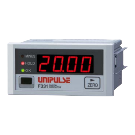
④ USB connector ③ Setting key (with a cap) ①Status display The F331 status is indicated. MINUS This LED turns on when the indicated value is minus. HOLD This LED turns on when the indicated value is the held value. -
Page 12: Rear Panel
1 OUTLINE ■Rear panel Chapter ③ Option slot ① Protective ground ② Signal input/output terminal block ①Protective ground This is a protective ground terminal block. Be sure to ground the protective ground terminal to prevent electric shocks and failures by static electricity. (The frame and protective ground terminal are conducted.) Do not use other screws than that attached to the main body (M4×8 binding-head machine screw with a toothed washer). - Page 13 1 OUTLINE 6・9・10: Terminals for outputting comparison. Selectable by setting. (OK/ NG/ HH/ HI/ LO/ LL) Chapter OUT1 (Initial value: HI) OUT2 (Initial value: LO) 11 to 13: Terminals for inputting power. The input voltage is DC24V (±15%). ③Options slot One option board can in stall in the option slot. - BCD parallel data output (BCO) - D/A converter (current output)
-
Page 14: Connection
2 CONNECTION CONNECTION Precautions about connection to the signal input/output terminal block are given below. Chapter The precautions described here are important for safety. Please properly understand the descriptions before connection. WARNING - Do not connect a commercial power source directly to the signal input/output terminals. -
Page 15: Connection Of The Signal Input/Output Terminal Block
Chapter Remove the terminal block from the F331 body with a strong pull. * The number of pins is 13. Loosen the screw with a screwdriver to open the hole. -
Page 16: Connection Of The Strain Gauge Sensor
With no mark: The excitation voltage is 2.5V. ■4-wire strain gauge sensor (+EXC) +OUT -OUT (-SIG) F331 (-EXC) (+SIG) (SHIELD) ■6-wire strain gauge sensor For connecting a 6-wire strain gauge sensor, short-circuit +EXC and +S, and -EXC and -S. (+EXC) -
Page 17: Connection Of The Power Input Terminal
- Be aware that the voltage drops depending on the wire thickness and length. Also, never input AC power source. Doing so will cause a failure. - Since the F331 has no power switch, install a breaker. - Be sure to ground the protective ground terminal to prevent electric shocks and failures by static electricity. -
Page 18: Connection Of The External Output (Sink Type)
The external output circuit is operated through an open collector. 6 is the common terminal. The open collector output capacity is 120mA and the withstand voltage is up to 30V. - Equivalent circuit Chapter Vext F331 Inside Spark killer Power supply Load... -
Page 19: Setting Method
Starting of the F331 PC application software ■Installation of the F331 PC application software Setting up the F331 by the F331 PC application software and use it for data management at system introduction and data analysis for troubleshooting. Please download and install it from the Unipulse homepage. -
Page 20: The Injection Of A Power Supply
Please check that a display comes. ■Starting of the F331 PC application software The F331 PC application software will start by executing an EXE file. If there is no shortcut on the desktop, please run the EXE file from the EXE file destination folder. -
Page 21: List Of Setting Values
3 SETTING METHOD 3-3. List of setting values ■Comparison setting Item Initial value Setting range Page HH limit +9999 -9999 to +9999 P. 16 HI limit +0750 -9999 to +9999 P. 16 LO limit +0250 -9999 to +9999 P. 16 LL limit -9999 -9999 to +9999 P. -
Page 22: Option Setting
3 SETTING METHOD ■Option setting Item Initial value Setting range Page 0: Linked with 0: Linked with indicated value, BCD output mode P. 27 indicated value 1: Not linked with indicated value 0: 300, 1: 100, 2: 50, 3: 30, BCD data update rate 0: 300 P. -
Page 23: How To Calibration
4 HOW TO CALIBRATION HOW TO CALIBRATION "Calibration" refers to an operation whereby matching between the F331 and a strain gauge sensor is obtained. The F331 uses the calibration methods as described below. ◇Zero calibration Register the initial zero point. Check around the strain gauge sensor for unwanted loads such as foreign object is placed or there is contact with peripheral equipment. -
Page 24: Equivalent Input Calibration Procedure
This function sets the Position of decimal point. 4-4. Equipment ID F331 can be set Equipment ID for identification. Equipment ID has Indicator ID and Loadcell ID. Setting be 20 bytes (20H to 60H, 7BH to 7EH) of ASCII code. -
Page 25: Setting Of Functions
5 SETTING OF FUNCTIONS SETTING OF FUNCTIONS 5-1. HI-LO limit comparison < Comparison conditions > - HH ON condition: Indicated value > HH limit value ( ⇔Indicated value displayed alternately) OFF condition: Indicated value ≦ HH limit value - HI ON condition: Indicated value >... -
Page 26: Hysteresis
5 SETTING OF FUNCTIONS 5-2. Hysteresis The hysteresis value may be determined so as to allow a margin for timing the turning off of the HI/ LO limit comparison. Normally, it is turned on when the indicated value exceeds the HI limit and is turned off when the indicated value falls below it. -
Page 27: Near Zero
5 SETTING OF FUNCTIONS 5-3. Near zero By this function, it is detected that the indicated value is near zero. ON condition: | indicated value | ≦ near zero setting value (0 is excluded.) OFF condition: | indicated value | > near zero setting value Point Near zero ON/OFF is closely related to the Comparison timing. -
Page 28: Hold Mode
5 SETTING OF FUNCTIONS 5-8. Hold mode ■Sample (The arbitrary points are held.) < Timing chart > Indicated value Sensor input value Time HOLD input Hold HOLD Chapter t1 to t3: MAX 20mS t1: Time from when the hold signal is inputted to when the indicated value is held t2: Time from when the hold signal is cancelled to when the indicated value returns to tracking t3: Minimum reset signal width required for canceling the hold ■Peak (The maximum point is held.) -
Page 29: Bottom (The Minimum Point Is Held.)
5 SETTING OF FUNCTIONS ■Bottom (The minimum point is held.) < Timing chart > Indicated value Sensor input value Time HOLD input Detection Hold Detection Hold HOLD blinking blinking Chapter t1 to t3: MAX 20mS t4: Approx. 0.5s t1: Time from when the hold signal is inputted to when the indicated value is held t2: Time from when the hold signal is cancelled to when the indicated value returns to tracking t3: Minimum reset signal width required for canceling the hold t4: Time after updating a hold value until it holds... -
Page 30: Digital Zero Function
5 SETTING OF FUNCTIONS 5-9. Digital zero function This function zeros the indicated value. ■Digital zero by key operation Press the ZERO When the indicated value becomes zero, digital zero is completed. Display Message description Invalid ZERO key operations. ■Digital zero by external signal input At the instant when the digital zero input (8) and COM (6) on the signal input/output terminal block at the back are short-circuited, the digital zero function works to zero the indicated value. -
Page 31: External Input/Output Signals
6 EXTERNAL INPUT/OUTPUT SIGNALS EXTERNAL INPUT/OUTPUT SIGNALS 6-1. Connector pin assignments 6 7 8 9 10 Signal input/output terminal block OUT1 OUT2 6-2. External input signals IN1: Hold/Judge IN2: Digital zero ■Hold/Judge <edge input> For hold signal, please use hold mode. Chapter Hold ON Hold OFF... -
Page 32: External Output Signals
6 EXTERNAL INPUT/OUTPUT SIGNALS 6-3. External output signals ■External output selection Each signal of comparison outputs is selectable by setting. OUT1: Output selection 1 OUT2: Output selection 2 Select from OK, NG, HH, HI, LO, and LL. External output selection Output selection 2* Output selection 1* * 0: OK 1: NG 2: HH 3: HI 4: LO 5: LL ■OK/ NG/ HH/ HI/ LO/ LL... -
Page 33: Bcd Data Output
7-1. BCD data output The BCD data output interface is used to obtain the indicated value of the F331 as BCD data. It is convenient for connecting the F331 with a computer, process controller, PLC, etc., to perform processing, such as controlling, aggregating, and recording. -
Page 34: Equivalent Circuit
7 OPTION ■Equivalent circuit Output F331 PLC input unit etc. +24V Sink type Plus common type +12V Vceo=30V(max) A2 to A13 Ic=50mA(max) B2 to B13 Output Input A1, B1 +24VRTN ● Internal transistor status ● Output pin level Output data Negative... -
Page 35: Connector Pin Assignment
7 OPTION ■Connector pin assignment Signal Signal 1000 2000 4000 8000 Output selection 1 Output selection 2 Minus (polarity) OVER STROBE BCD data hold Logic switching N.C. N.C. N.C. N.C. Compatible connector: FCN-361J032-AU (manufactured by Fujitsu Component or an equivalent) Connector cover: FCN-360C032-B (manufactured by Fujitsu Component or an equivalent) Output selection 1, Output selection 2 (Linked with indicated value) Output signal can be assigned. -
Page 36: Bcd Output Mode
Negative logic Positive logic Undefined section (20ms or less) ■BCD output mode Set the BCD output mode of F331. Linked with indicated value Chapter Output linked with indicated value. When the indicated value is held, the held value is outputted even if the sensor input signal changes. -
Page 37: D/A Converter
■Current output (DAI option) This converter is used to obtain an analog output which is linked with the indicated value of the F331. The range of the analog output is from 4 to 20mA. An analog output from 4mA to 20mA can be obtained with respect to any digital values set by the D/A zero scale setting and the D/A full scale setting functions. - Page 38 - Do not apply external currents. Breakage will result. Also, connecting a capacity load may cause oscillation. Setting of D/A zero and gain With the D/A converter of the F331, an analog Current (mA) output is obtained by setting the indicated value...
-
Page 39: D/A Zero And Full Scale
Also, the minimum unit of indicated value is: (D/A full scale - D/A zero scale) × 1/10000. ■D/A zero and full scale Set the D/A zero and full scale of the F331. * Please be sure to set up zero scale < full scale. ■D/A output mode Set the D/A output mode of the F331. -
Page 40: Rs-485 Interface
7-3. RS-485 interface The RS-485 interface is used to read out the indicated value and the state of the F331 and to write set values into the F331. It is convenient for connecting the F331 with a PLC/programmable display, etc., to perform processing, such as controlling, aggregating, and recording. -
Page 41: Rs-485 Connection
- Install terminating resistance each on the Terminating resistance host side and F331 side. (110Ω) self-contained On the F331 side, connect Rt. and B+ with a short bar. - The terminal SG is a grand terminal used on the circuit for protecting the circuit. -
Page 42: Rs-485-Related Setting Values
7 OPTION ■RS-485-related setting values ■RS-485 I/F setting Set the RS-485 port of this device. * If the communication mode is Modbus-RTU, set as length of character: 8 bits and stop bit: 1 bit (stop bit: 2 bits if the parity bit is none). RS-485 I/F setting (Initial value: 41200) Baud rate... -
Page 43: Uni-Format Commands
19200 bps times/sec. 9600 bps times/sec. 4800 bps times/sec. 2400 bps times/sec. 1200 bps ■UNI-Format commands ■Command communication formats - Read the linked with indicated value (sign, 5-digit, decimal point) IDNo. Host + 0 1 0 Delimiter F331 IDNo. 0 fixed... - Page 44 0: OFF 1: ON OFL2 0: OFF 1: ON OFL1 0: OFF 1: ON 0: OFF 1: ON 0: OFF 1: ON Calibration error No. F331 error No. - Status 2 IDNo. Host 0 0 0 Delimiter F331 IDNo. Under a hold/ Under a judgment...
- Page 45 7 OPTION - Zero calibration Host Delimiter F331 IDNo. Calibration in progress IDNo. Normal end 2 - 9: F331 error No. Calibration disabled by calibration LOCK Calibration in progress - Actual load calibration Host Delimiter F331 IDNo. Calibration in progress IDNo.
- Page 46 7 OPTION - Hold/Judge OFF Host F331 * No data returned IDNo. - Digital zero Host F331 * No data returned IDNo. - Digital zero reset Host F331 * No data returned IDNo. ■Setting value communication formats These are used for reading (returned data) and writing setting values.
- Page 47 * Values other than "0" should not put in places where "0" is set. Attention - After receiving a response from the F331, keep an interval of 5mSec or more until sending the next command from the host. 5mSec or more Host ・...
-
Page 48: Uni-Format (Continuous)
F : Comparison OFF 3 : 0.000 Order of priority: N, F > (H or L) > G * If two or more F331 are connected, do not specify continuous mode. ■Modbus-RTU ■Transmission delay time Set this when the master equipment cannot process responses from the F331. - Page 49 7 OPTION ■Function codes for Modbus Function codes are explained in detail. In this chapter, function fields and data fields varying by function codes are explained. Each actual message frame consists of an address field, function field, data field, and error check field, which are transmitted in this order.
- Page 50 Keep in mind that the relative address for reading the digital zero value is 0x02. In cases less than 8 bits, the remainder bits become "0". * The F331 response (coil state) is always "0" (because processing is executed at the stage of reading the command).
- Page 51 LO limit; higher LO limit; lower Chapter Keep in mind that the relative address for reading the HI limit value is 0x01. The example shows the case where the F331 settings are as follows: 100 (0x0064) HI limit 50 (0x0032)
- Page 52 Keep in mind that the relative address for reading the linked with indicated value is 0x03. The example shows the case where the indicated value of the F331 is as follows: Linked with indicated value: 1000 (0x03E8) 05 (0x05) Write single coil A slave coil is changed to ON or OFF.
- Page 53 7 OPTION 06 (0x06) Write single register A slave holding register is changed (rewritten). If broadcast (0) is specified, all slave holding registers of the same address are rewritten. To request, specify the holding register address and change data. [Request] byte Function 0x06 byte...
- Page 54 (Hold/judge ON - digital zero reset) Keep in mind that the relative address for writing in the hold/judge ON is 0x00. The example shows rewriting of the F331 ON (1)/OFF (0) as follows: Fill unused bits with "0". Coil 00008...
- Page 55 Example) Change the moving average filter (address 40009) to 20 (0x0014) and digital low pass filter to 6Hz (*). * Select the F331 digital low pass filter setting from: 0: 3Hz, 1: 6Hz, 2: 12Hz. Write "1" for 6Hz in the example.
- Page 56 7 OPTION 12 (0x0C) Get comm event log This function is to read the event conditions from each slave. The contents of status and event counter are the same as status 11 (Get comm event counter). The message count is the same as subfunction 11 (Return bus message count) of status 08. As events, 64 byte conditions in which the slave receives and sends messages are held.
- Page 57 ◎ Receiving event (when bit 7 is "1") Unused Communication error Unused Unused Character overrun In listen-only mode ("0" on the F331) Receiving broadcast ◎ Sending event (when bit 7 is "0") Sending exception code 1 to 3 Sending exception code 4 Send and write timeout In listen-only mode ("0"...
- Page 58 7 OPTION 17 (0x11) Report slave ID Each slave returns operation mode, current conditions, etc. The contents of the response vary with products. [Request] byte Function 0x11 [Response] byte Function 0x11 byte Number of bytes byte Slave ID 0x00: Overload or calibration error byte RUN indicator 0xFF: Normal...
- Page 59 Clear overrun counter and flag Clear the character overrun error counter * Code 03, 05 to 09, and 16 are not supported by the F331. * Code 04 brings about receive-only mode, while additions to each counter and event log (always 0x04 when in code 04) are executed.
- Page 60 7 OPTION 02 (0x0002) Return diagnostic register (not supported by the F331) Request frame is returned as it is. byte [Request] Function 0x08 byte Subfunction 0x00, 0x02 byte Data N×2 Desired 16-bit data [Response] Echo of request 04 (0x0004) Force listen only mode Slave is brought into receive-only mode.
- Page 61 7 OPTION 12 (0x000C) Return bus communication error count The total number of CRC errors detected by slave is read. byte [Request] Function 0x08 byte Subfunction 0x00, 0x0C byte Data 0x00, 0x00 [Response] byte Function 0x08 byte Subfunction 0x00, 0x0C byte Data CRC error count 13 (0x000D) Return bus exception error count...
- Page 62 Subfunction 0x00, 0x11 byte Data Busy 18 (0x0012) Return bus character overrun count (not counted up by the F331) The number of times of detecting a character overrun error in frames consistent in slave address is read. [Request] byte Function...
- Page 63 7 OPTION Exception code = 01 A nonexistent function code has been specified. Check the function code. Exception code = 02 An unusable address has been specified. - Check the start address or start address + (number of coils or number of statuses or number of registers).
- Page 64 7 OPTION ■Data address Setting Calibration Data type Address Data name Data format LOCK LOCK 00001 Hold/judge ON 00002 Hold/judge OFF 00003 Digital zero 00004 Digital zero reset Coil 0XXXX 00005 Zero calibration ○ 00006 Actual load calibration ○ 00007 Equivalent input calibration ○...
- Page 65 7 OPTION Point The address number used on a message is a relative address. The relative address is calculated by the following equation. Relative address = Last 4 digits of address No. - 1 For example, it is 0014 (0x0E) when holding register 40015 is designated. * Status 1 (abnormal condition) Undefined Calibration error (0 - 9)
-
Page 66: Setting Value Lock/ Calibration Value Lock
7 OPTION * Status 2 (weighing condition) Undefined Under a hold/ under a judgment Undefined 15 14 13 12 11 10 9 "1" when each status is ON. * Status 3 (weighing condition) Decimal place Undefined Setting value LOCK Calibration value LOCK Undefined 15 14 13 12 11 10 9 - Decimal place:... -
Page 67: Rs-232C Interface
7-4. RS-232C interface The RS-232C interface is intended to read the indicated value and status of the F331 and read/write setting values with the F331. It is convenient for processing of control, compilation, recording, etc., as the F331 is connected to a computer, PLC, etc.. -
Page 68: Rs-232C-Related Setting Values
7 OPTION ■RS-232C-related setting values ■RS-232C I/F setting Set the RS-232C port of this device. RS-232C I/F setting (Initial value: 41200) Baud rate Delimiter 0: 1200bps 0: CR 1: 2400bps 1: CR+LF 2: 4800bps Stop bit 3: 9600bps 0: 1bit 4: 19200bps 1: 2bit 5: 38400bps Parity bit... -
Page 69: Command Communication Formats
F331 0 fixed - Status 1 Host 0 0 0 Delimiter F331 Calibration error No. F331 error No. 0: OFF 1: ON 0: OFF 1: ON OFL1 0: OFF 1: ON OFL2 0: OFF 1: ON -LOAD 0: OFF 1: ON... - Page 70 * For setting value No., see "■Setting value communication formats" on page 63. - Zero calibration Host Delimiter F331 Normal end Calibration in progress 2 - 9: F331 error No. Calibration disabled by calibration LOCK Calibration in progress - Actual load calibration Host Delimiter F331...
- Page 71 - Equivalent input calibration Host Delimiter F331 Normal end Calibration in progress 2 - 9: F331 error No. Calibration disabled by calibration LOCK Calibration in progress Attention Please set up capacity value before sending the command of actual load calibration.
-
Page 72: Setting Value Communication Formats
7 OPTION ■Setting value communication formats These are used for reading (returned data) and writing setting values. Chapter Read: Delimiter sign or 0 Setting value No. Setting value up to 5 digits * Values other than "0" should not put in places where "0" is set. - Page 73 * Values other than "0" should not put in places where "0" is set. Attention Chapter After receiving a response from the F331, keep an interval of 5mSec or more until sending the next command from the host. 5mSec or more Host ・...
-
Page 74: Continuous Transmission Formats
7 OPTION ■Continuous transmission formats - Transmission format 1 9 10 11 12 13 14 15 16 17 18 19 20 21 *5 , Delimiter ± Sign + or - 5-digit linked with indicated value decimal point - Transmission format 2 9 10 11 12 13 14 15 16 17 18 19 20 21 22 23 *1 *2 *3 *4... -
Page 75: Specifications
8 SPECIFICATIONS SPECIFICATIONS 8-1. Specifications ■Analog section Sensor excitationvoltage DC2.5V or 5V±10% (designated when ordered) Output current within 30mA Signal input range -3.0 to 3.0mV/V Equivalent input calibration range 0.5 to 3.0mV/V Equivalent input calibration error Within 0.1%FS (at 0.5mV/V input) Accuracy Non-linearity Within 0.02%FS (at 3mV/V input) -
Page 76: External Signals
8 SPECIFICATIONS (Output selection1, Output selection 2), D/A output mode, D/A zero scale, D/A full scale, RS-485 communication mode, RS-485 I/F setting (baud rate, Length of character, Parity bit, Stop bit, Delimiter), RS-485 ID, RS-485 transmission delay time, RS-232C communication mode, RS-232C I/F setting (baud rate, Length of character, Parity bit, Stop bit, Delimiter), Setting value LOCK (485/232), Calibration value LOCK (485/232) - Page 77 8 SPECIFICATIONS Rated voltage Rated current 50mA Insulation method Photo coupler insulation Input signal BCD data hold, logic switching Input type Dead-front contact input (self-contained power supply) Relay, switch, and transistor, etc. can be connected. The signal is inputed by short-circuited and opening the input terminal of the terminal COM.
-
Page 78: General Specifications
8 SPECIFICATIONS RS-232C communication interface [232] Signal level: RS-232C-compliant Transmission mode: Asynchronous, full-duplex communication Transmission speed: 1200, 2400, 4800, 9600, 19200, 38400bps selectable Bit configuration: Start bit 1 bit Length of character 7 or 8 bits selectable Stop bit 1 or 2 bits selectable Parity bit None, odd, or even selectable Code... -
Page 79: Dimensions
8 SPECIFICATIONS 8-2. Dimensions Chapter... -
Page 80: When The Bcd Output Option Is Equipped
8 SPECIFICATIONS ■When the BCD output option is equipped Chapter... -
Page 81: When The D/A Converter Option Is Equipped
8 SPECIFICATIONS ■When the D/A converter option is equipped Chapter... -
Page 82: When The Rs-485 Option Is Equipped
8 SPECIFICATIONS ■When the RS-485 option is equipped Chapter... -
Page 83: When The Rs-232C Option Is Equipped
8 SPECIFICATIONS ■When the RS-232C option is equipped Chapter... -
Page 84: Mounting On A Panel
8 SPECIFICATIONS 8-3. Mounting on a panel Install the F331 in a control panel by the following procedures. Make a hole in the panel according to the panel cutout dimensions. Panel cutout size [Unit: mm] 92(W)×45(H) (mm) Mounting panel thickness 1.6 to 3.2 (mm) Remove the guide rails from both sides. -
Page 85: Block Diagram
8 SPECIFICATIONS 8-4. Block diagram + SIG Input Conversion Amplifier 24bit - SIG + EXC Base Excitation Voltage Voltage - EXC 2.5V or 5V SHIELD FRAME Serial Serial Watchdog Port Port 16bit 12KB NOVRAM 128KB 4096bit Serial Serial Port Port * 1 Option Output Driver... -
Page 86: Supplements
Strain gauge type sensor output is outside the F331’s allowable Chapter sensor input range. Check if the sensor is properly loaded, and the its rated output falls within the F331’s sensor input range. Perform Span calibration again. Then, perform Span calibration again. ■Message display... -
Page 87: Self-Check/Initialization
9 SUPPLEMENTS 9-2. Self-check/initialization ■Self-check (at power-on) This device is provided with the self-check function to automatically check the memory and detect abnormality and the visual-check function by which the display can be checked visually. Turn on the power while pressing the key. - Page 88 Unipulse Corporation International Sales Department 9-11 Nihonbashi Hisamatsucho, Chuo-ku, Tokyo 103-0005 Tel: +81-3-3639-6120 Fax: +81-3-3639-6130 http://www.unipulse.com/en/ Head Office: 9-11 Nihonbashi Hisamatsucho, Chuo-ku, Tokyo 103-0005 Technical Center: 1-3 Sengendainishi, Koshigaya, Saitama 343-0041 Nagoya Sales Office: CK16 Fushimi Bldg 1-24-25 Sakae, Naka-ku, Nagoya 460-0008...
Need help?
Do you have a question about the F331 and is the answer not in the manual?
Questions and answers