Table of Contents
Advertisement
Quick Links
Advertisement
Table of Contents

Subscribe to Our Youtube Channel
Related Manuals for Silca Unocode 399 Plus


Summary of Contents for Silca Unocode 399 Plus
- Page 1 Operating manual D437711XA vers. ®...
- Page 2 This manual is written by SILCA S.p.A. All rights reserved. No part of this publication may be reproduced or used in any form or by any means (photocopying, microfilm or other) without the written permission of SILCA S.p.A. Edition: october 2010 Printed in Vittorio Veneto by SILCA S.p.A.
-
Page 3: Table Of Contents
INDEX REFERENCE GUIDE .....................1 GENERAL .......................2 MACHINE DESCRIPTION ................4 ................4 AIN CHARACTERISTICS ......................5 AFETY .................. 6 AIN WORKING PARTS ..................8 ECHNICAL ................9 CCESSORIES PROVIDED TRANSPORT ....................10 ....................10 ACKING ....................11 NPACKING .................. - Page 4 CLEANING ....................62 MAINTENANCE .....................63 ................... 63 ROUBLE SHOOTING ................ 65 AINTENANCE OPERATIONS ................65 UTTER REPLACEMENT .......... 66 ELT REPLACEMENT AND TENSION ADJUSTMENT ............67 HECKING AND OR REPLACING FUSES ..........68 LECTRONIC CIRCUIT BOARD REPLACEMENT ..
-
Page 5: Reference Guide
REFERENCE GUIDE This manual has been produced to serve as a guide for user s of the UNOCODE 399 PLUS electronic key- cutting machine. Read it carefully; it is essential if you wish to operate your machine safely and efficiently. -
Page 6: General
If the key-cutting machine is used differently or for purposes different from those described in this manual, the customer will forego any rights he may have over Silca S.p.A. Furthermore, unforeseen danger to the operator or any third parties may arise from incorrect use of the machine. - Page 7 Operating manual - English Unocode 399 PLUS • Machine identification The machine is provided with an identification label which includes the machine’s serial number (fig. 3). Fig. 3 (*) see chap.8 "DISPOSING OF MACHINE", page 76. Copyright S ilca 2010...
-
Page 8: Machine Description
Operating manual - English MACHINE DESCRIPTION UNOCODE 399 PLUS i s an electronic machin e o perating on two a xes (3rd axis op tional) with controlled movement. Accurately studied, it adds a high degree of cutting precision to operating speed and ease of use. -
Page 9: Safety
The cutter motor is pr otected against overheating by a cut-out switch (located insi de the motor ) that will automatically stop the motor if it reaches a certain temperature. Should the switch activate: 1) turn the machine off and disconnect the power supply cable. 2) contact Silca’s Technical Assistance Dept. Copyright S ilca 2010... -
Page 10: Main Working Parts
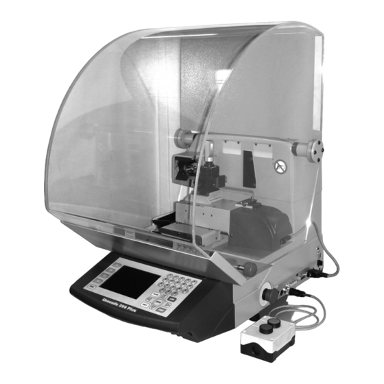
Unocode 399 PLUS Operating manual - English AIN WORKING PARTS Fig. 5 Copyright S ilca 2010... - Page 11 Operating manual - English Unocode 399 PLUS Fig. 6 A - master switch A1 - power socket / fuse tray B - k eyboard C - display D - clamp - cutter side E - clamp knob F - key gauge...
-
Page 12: Technical Data
Unocode 399 PLUS Operating manual - English ECHNICAL Electricity supply: 230V-50Hz Nominal power: 230V: 1,1 Amp. 210 Watt cutter motor: single phase and speed cutter: hard metal Tool speed: • 50Hz: 2370 rpm (+/- 10%) Movements: on 2 axes with ball screws activated by step motors, on rectified roller guides. -
Page 13: Accessories Provided
Operating manual - English Unocode 399 PLUS CCESSORIES PROVIDED UNOCODE 39 9 PLUS comes with a set of acce ssories for its oper ation and maintenance ( tools, hex wrenches, fuses) supplied in a special tool kit comprising: tool kit... -
Page 14: Transport
Unocode 399 PLUS Operating manual - English TRANSPORT The key-cutting machine is easily transported and is not dangerous to handle. The packed machine should be carried by at least two people. ACKING The packing for UNOCOD E 399 PLUS is design ed to ensure safe tr ansportation and to protect the machine and all its parts. -
Page 15: Unpacking
Note: we strongly recommend you keep the packing intact for future transportation ACHINE HANDLING When the UNOCODE 399 PLUS has been unpacked, place it directly on its workbench; this operation should be carried out by at least two people. Take care to lift the machine firmly holding the base, and no other part. -
Page 16: Machine Installation And Preparation
Unocode 399 PLUS Operating manual - English MACHINE INSTALLATION AND PREPARATION The key-cutting machine can be installed by the purchaser and does not require any special skills. It is supplied ready for use and does not need any special set up. However, the operator may have to control a few things before operating the machine. -
Page 17: Description Of Work Station
Operating manual - English Unocode 399 PLUS ESCRIPTION OF WORK STATION The machine needs only one operator, who has the following controls at his/her disposal (fig. 5, page 6): • master switch placed on the back of the machine •... -
Page 18: "Set Up" And Use Of The Machine
Unocode 399 PLUS Operating manual - English “SET UP” AND USE OF THE MACHINE SE OF THE CLAMP The four-sided clamp ensures excellent grip on the keys placed on their back or profile sides (fig. 12). • Keys with 1 or 2 cuts should be fitted mainly on the A and/or B side of the clamp. - Page 19 Operating manual - English Unocode 399 PLUS ATTENTION: the knob is gauged so that it do not exert too much pressure for closing (if pressure is too high it only idles), which would damage the key and the parts of the clamp (including the knob).
-
Page 20: Fitting The Clamp To The Machine
Unocode 399 PLUS Operating manual - English ITTING THE CLAMP TO THE MACHINE To remove the clamp unit: loosen the grub s crew (D2) ( fig. 17) and s lide the clamp out of the dovetail guide. To install the clamp unit on the machine:... -
Page 21: Operating Guide
Unocode 399 PLUS OPERATING GUIDE Introduction The Operating Gu ide belo w expl ains h ow to use the UNOCODE 399 PLUS wi thout a Person al Computer. All operations to manually use the key-cutting machine are explained step by step. -
Page 22: Preliminary Operations
Unocode 399 PLUS Operating manual - English RELIMINARY PERATIONS 1) place the key-cutting machine on the work top. 2) connect the power lead to the mains (cap.3.3, page 12). 3) make sure that the emergency button (N, fig. 5, page 6) is not turned on. -
Page 23: Copy By Data Card
• USER data cards This is a data card customized by the user with Silca Ke y Prog rams on a PC an d sent to the machine. It may be: created by the SKP Code Maker a Silca SKP data card with certain parame- ters edited. - Page 24 Unocode 399 PLUS Operating manual - English • CODEMAKER data card: Data card customized by the u ser, crea ted with the CODEMAKER fu nction on th e machin e (see cap.5.6, page 36). • From the init ial scr een “Copy by da ta card”...
- Page 25 Side 1 / Side 2 Double asymmetrical cuts Fig. 23 (*) Adapter on certain data cards provided by Silca the parameter “Adapt: B...” ind icates the type of accessory needed to cut a key. 3) Digit the cuts. In the cut entry field: The dots shown represent possible cuts.
- Page 26 Unocode 399 PLUS Operating manual - English 5) Enter the quantity of keys to be cut (max.999) Accessory functions (chap.5.3.2, page 25) Press F4 to view all the functions number of pieces to cut Fig. 24 6) Press ENTER. Accessory functions (chap.5.3.2, page 25)
- Page 27 Operating manual - English Unocode 399 PLUS 7) Press START. TO CUT ON BOTH SIDES: Turn the key and cut the second side if the key is symmetrical, as in this case. Press START. 8) Press STOP and remove the key.
-
Page 28: Favourite Data Cards
Unocode 399 PLUS Operating manual - English 5.3.1 AVOURITE DATA ARDS Frequently u sed data card s (SILCA, USER or CODEMAKER data card s), sav ed in Favourites menu (c hap.5.3.2 "ACCESSORY FUNCTIONS FOR “COPY BY DATA CARD”", page 25). -
Page 29: Accessory Functions For "Copy By Data Card
Operating manual - English Unocode 399 PLUS 5.3.2 ACCESSORY FUNCTIONS FOR “COPY BY DATA CARD” a) Data Card Decoding FUNCTION NOT AVAILABLE ON THIS MACHINE b) Manual Adjustments • Press F2 to set manual adjustment to cutting depths and spaces. - Page 30 Unocode 399 PLUS Operating manual - English c) Save Data Cards in the Favourites menu Press F3 to save in the Favourites Menu: a SILCA data card a USER data card a CODEMAKER data card From the keyboard digit a number from 1 to 0 to assign a p osition to the data ca rd to be saved.
- Page 31 Operating manual - English Unocode 399 PLUS d) Data Card Parameters Function used to view the tech nical data relating to the data card. • Press • Press Key blank measurements * Cutting angle Key stop Symbols associated to cutting depths *...
- Page 32 Unocode 399 PLUS Operating manual - English e) Copy SILCA Data Card in CODEMAKER Function u sed to copy a SILCA d ata card into CODEMAKER and edit some of the parameters. • Press F4. • Press F2. ATTENTION:not all SILCA data cards can be copied into CODEMAKER.
- Page 33 ERTICAL Necessary for special keys with sm all bits (Silca art. FO19 P, FO21P...) where a special cutter is required. When th is cutti ng metho d is use d a sp ecial angl ed cu tter is needed.
- Page 34 THIS MACHINE h) Key Blank Measurement Function used to edit the key blank measurement. The key blank figure in the database refers to a key produced by Silca. Key Blank measurement Figura 27 1) Press F3 to vary the set measurement for the key blank to be cut.
-
Page 35: Special Cases
Example: 1) Enter data card number 2) Press ENTER 3) Enter the cut 4) Press ENTER The Silca software calculates the validity of the data entered. If they are not cong ruous the fo llowing message will appear: NON-FEASIBLE COMBINATION This message is explained below. -
Page 36: Imited Access To Ata Protected Systems
5.4.2 IMITED ACCESS TO PROTECTED SYSTEMS Silca has limited access to some of the data in the Database in agreement with certain manufacturers. Limitations are applied to: DATA CARD, if the key-cutting card is protected, access is denied. To access protected data: a) apply to the manufacturer for authorization. -
Page 37: Pc Queue Function
“+” sign will indicate that the cycle is finished. Should a work queue be interrupted, turn off the UNOCODE 399 PLUS. When the machine is turned on again and the <PC queue> is called up, the list reappears, starting from the first line. - Page 38 Operating manual - English “CUTTING METHOD” Accessory Function • Press F1 to view the CUTTING METHOD set by Silca for the data card involved. “KEY BLANK MEASUREMENT” Accessory Function • Press F3 to alter the setting for the measurement of the key blank to be cut.
- Page 39 Operating manual - English Unocode 399 PLUS 5) Position the second side of the key to be cut. 6) Press START, the display will show: When the secon d si de ha s been cut, the display will show: •...
- Page 40 • Delete a data card (F3) • Copy a data card (F4 then F1) • Copy a SILCA data card (F4 then F2) NOTE: creating of new cards is allowed for two key types: SINGLE side DOUBLE SYMMETRICAL side • Creating new data Card...
- Page 41 Operating manual - English Unocode 399 PLUS Step 3 • Insert the de pth symbol ( number or letter). Press ENTER. • Enter the d epth m easurement associated t o the symbol. Press ENTER. Repeat the operation to the last depth.
- Page 42 Unocode 399 PLUS Operating manual - English • Edit Data Card This function is u sed to edit a card previo usly created by CODEMAKER. • Select the data card from the list and press F2. • Follow the proce dure de scribed i n “ Create a new Data Card”...
- Page 43 • Import SILCA Card This fun ction is used to copy an original SIL CA data card and edit its parameters. • Press F4 then F2. • Enter the number of the SILCA data card to be copied. • Press NTER. •...
-
Page 44: Codemaker Card Management Gauging
Unocode 399 PLUS Operating manual - English GAUGING The following components on th e machine have a specific ‘ self-setting’ p rocedure wi th the u se o f regulating templates (chap.1.5 "Accessories provided", page 9): CLAMPS CUTTERS ADAPTERS CUTTERS do not need an automatic calibration system. -
Page 45: Calibrate Standard Jaws
4) Press ENTER, the display will show: 5) Make sure the U01W stan dard pris matic cutter is installed. ATTENTION:if the original Silca U01W cutter is replaced with one that is NOT original or has been sharpened, it will be necessary to repeat clamp calibration and also gauge all the optional cutters. - Page 46 Unocode 399 PLUS Operating manual - English 11) Enter the values for A and B, expressed in hundredths of a millimetre, into the special fields. Nota bene: values are accepted if they are the same or differ by +/- 40 hundredths of a millimetre from the theoretical value.
-
Page 47: Calibrate Cutters
Y positive value: raise the cut Y negative value: lower the cut ATTENTION:if the original Silca U01W cutter is replaced with one that is NOT original or has been sharpened, it will be necessary to repeat clamp calibration and also gauge all the optional cutters. -
Page 48: Maintenance
Unocode 399 PLUS Operating manual - English MAINTENANCE From the initial screen press MENU then F2 to enable the function. Use the up/down arrow keys to select the option and press ENT ER, or di rectly press the key relating to the option number. -
Page 49: Digital Outlets Tests
In the case of the cutter, the motor will also start. In the case of the cutting side or reading lamp, the one in question will illuminate momentarily. Note: if this is not so, contact Silca’s Technical Assistance Dept. This test (Exit...) can be carried out only whe n an automatic fe eder (or o ther option al compo nent) is installed on the machine. -
Page 50: Machine Zero Points
Unocode 399 PLUS Operating manual - English 5.8.7 MACHINE ZERO POINTS With the use of regulating templates (chap.1.5 "Accessories provided", page 9) the machine provides a ‘self-setting’ procedure. These procedures must be carefully carried out following the descriptions and illustrations indicated below. - Page 51 Operating manual - English Unocode 399 PLUS Press ENTER to continue, the display shows: Read the instructions on the display and fit the Z20 template into the cutter side of the clamp, with Stop 0 as the reference. Fig. 34 Lower the gauge and press ENTER to continue.
- Page 52 Unocode 399 PLUS Operating manual - English Press START, the display will show: Press ENTER to confirm, only if the previ ous parameters were ON (***). Press ST OP to cance l th e ope ration an d not confirm the adjustments made (if there is one value or more on OFF).
-
Page 53: Photocells And Sensors Regulation
Operating manual - English Unocode 399 PLUS 5.8.8 PHOTOCELLS AND SENSORS REGULATION PRELIMINARY OPERATIONS 1) turn the machine off and unplug it from its power supply cable. 2) remove the back panel (chap.7.8). 3) loosen the (G1) and (G2) grub screws that secure the X axis photocell disk (fig. 36). - Page 54 Unocode 399 PLUS Operating manual - English Y axis photocell: • manually turn the Y axis disk (fig. 38) up until the display’s description changes from OFF to ON. • use the provided allen key to tighten the (G3) grub screw.
- Page 55 Operating manual - English Unocode 399 PLUS Y axis sensor Figura 39 bottomview ATTENTION: if it is necessary to work close to this area with the machine turned on (e.g. to regulate the X axis sensor) take great care not to touch any components on the machine’s...
-
Page 56: Options
Unocode 399 PLUS Operating manual - English OPTIONS From the initial screen, press MENU then F3 to enable the function. There are 4 machine option windows that are selected by pressing F4. ATTENTION: Hold down F4 to take the machine back to its initial state (with the original parameters set by Silca). - Page 57 Operating manual - English Unocode 399 PLUS Machine options [page 2/4] the display shows: Machine data Model: machine model. Serial No: the serial number corresponding to th at on the ID plate located on the back of the machine. Keys cut: cutting completed.
- Page 58 Unocode 399 PLUS Operating manual - English Machine options [page 4/4] The display shows: Clock management Date and time format: use the arrow keys (rh/lh) to select the DATE format (DD/ MM/YY by default, or MM/DD/YY or YY/MM /DD) and TIME format (0 - 24 by default or am - pm) required, then press ENTER to confirm.
-
Page 59: Enabling
Operating manual - English Unocode 399 PLUS 5.10 ENABLING From the screen, press MENU and/or F4 to enable the function. This dis play shows all the protected systems enabled and allows them to be protected again, if necessary. E.g.: In thi s case a singl e protected card h as been previously enabled. -
Page 60: Messages
Unocode 399 PLUS Operating manual - English 5.11 ESSAGES 5.11.1 A TTENTION MESSAGES Data card not available! • The entered data card number is not available in the machine’s data base. Non-feasible combination! • The entered cuts cannot be carried out (see chap.5.4, page 31). - Page 61 Resetting of original machine data Confirm operation? No=STOP Yes=ENTER • This message appears if you wish to reset the machine on the initial settings, i .e. with the default parameters set up by Silca (see chap.5.9, page 52). Copyright S ilca 2010...
-
Page 62: Error Messages
Machine ID is set. Select menu 5.10 "ENABLING"and check that the Machine ID is different from 0. To set M achine ID ask for a Software update valid for yo ur machine and install with the S ILCA WinTransfer Program or SILCA Code Program. Copyright S ilca 2010... -
Page 63: Alarm Messages
Operating manual - English Unocode 399 PLUS 5.11.3 A LARM MESSAGES ALARM 2 TEMPERATURE ALARM Turn the machine off! • The electronic control board has exceeded the maximum permitted temperature. Check the cooling fan (SEE chap.7.1 "Trouble shooting", page 63). -
Page 64: Codemaker Messages
Unocode 399 PLUS Operating manual - English 5.11.4 CODEMAKER MESSAGES Key Blank dimension out of range! Limit values: • Appears when the depth value exceeds the key blank measurement assigned to the key. Cutting angle out of range! Limit values: •... - Page 65 Operating manual - English Unocode 399 PLUS The cut depth is not compatible with cutting edge of the cutter. See operating manual. • Appears when the cutting depth would not allow the cutter to move sideways. The cut depth exceeds...
- Page 66 Unocode 399 PLUS Operating manual - English CLEANING • keep the operational parts of the machine as clean as possible by brushing away the chippings in areas where they accumulate during cutting operations. • under no circumstances must compressed air be used to clear the work zone of chippings as this will blow them onto the moving parts.
- Page 67 WARNING: this may derive from inappropriate or heavy use of the key-cutting machine or a fault with the motor itself. DO NOT USE THE MACHINE and call Technical Silca Dept. to determing the cause of activation of the cut-off.
- Page 68 Unocode 399 PLUS Operating manual - English FAULT PROBABLE CAUSE The display sho ws t he check that the fan on the back of the key-cutting machine is working: message: Not working: a) fan faulty ‘TEMPERATURE b) electronic control board faulty...
- Page 69 Operating manual - English Unocode 399 PLUS AINTENANCE OPERATIONS • Cutter replacement • Belt replacement and tension adjustment • Fuse check and replacement • Electronic circuit board replacement • Keyboard/display replacement • Access to back compartment • Access to bottom compartment •...
- Page 70 Unocode 399 PLUS Operating manual - English ELT REPLACEMENT AND TENSION ADJUSTMENT To replace the belt, proceed as follows: 1) turn the machine off and unplug it. 2) remove the back panel (chap.7.8, page 70). 3) remove the bottom panel (chap., page 70).
- Page 71 Fuses must always be replaced with the same amper age and type (rapid or delayed), as indicated in this manual. There are 6 fuses in the UNOCODE 399 PLUS. • 2 fuses: 4 Amps rapid (230V)
- Page 72 Unocode 399 PLUS Operating manual - English LECTRONIC CIRCUIT BOARD REPLACEMENT Proceed as follows: 1) turn the machine off and unplug it from its power supply cable. 2) remove the bottom panel (ch., page 70). 3) disconnect all cable connectors from the electronic circuit board (fig. 50).
- Page 73 Operating manual - English Unocode 399 PLUS EYBOARD DISPLAY REPLACEMENT 1) turn the machine off and unplug it from its power supply cable. 2) loosen the 4 scr ews ( W4) and r emove the support (W3). 3) remove the display’s support, by unscrewing the 2 (B1) fixing screws (fig.
- Page 74 Unocode 399 PLUS Operating manual - English CCESS TO BACK OMPARTMENT To gain a ccess to the back c ompartment, proceed as follows: 1) turn the machine off and unplug it from its power supply cable. 2) remove the vacuum system’s connector (U2) (fig.
- Page 75 Operating manual - English Unocode 399 PLUS 7.10 ENSOR REPLACEMENT AXIS SENSOR REPLACEMENT 1) turn the machine off and unplug it from its power supply cable. 2) remove the bottom panel (chap. "To gain access to the bottom compartment, proceed as follows:").
- Page 76 Unocode 399 PLUS Operating manual - English AXIS SENSOR REPLACEMENT 1) turn the machine of f and unplug it from its power supply cable. 2) raise the protective shield. 3) disconnect the (J 1) Y axis cab le from the carriage (fig.
- Page 77 Operating manual - English Unocode 399 PLUS 7.11 HOTOCELL REPLACEMENT EPLACING THE AXIS PHOTOCELL 1) turn the machine off and unplug it from its power supply cable. 2) remove the back panel (chap.7.8 "Access to back Compartment"). 3) unscrew the 2 (G) screws that secure the photocell card and remove.
- Page 78 Unocode 399 PLUS Operating manual - English 7.12 ATTERY REPLACEMENT Replacing the battery is a simple operation but must be carried out with care. 1) Disconnect the power lead from the key-cutting machine. 2) Gain access to the bottom compartment.
- Page 79 - continue with the gauging of remaining jaws used. At this point the machine is set up and ready for operation. • SILCA update for the program or machine data 1) Install the WinTransfer Program update on your personal computer, following the instructions in the program.
- Page 80 • For information about the collection system for such appliances please contact SILCA S.p.A. or another subject registered in the various National Rolls for other countries in the European Union. Household waste (or of similar origin) can be included in the separate collection system for urban waste.
- Page 81 Unocode 399 PLUS ASSISTANCE Silca provides full s ervice to pur chasers of the UNOCODE 399 PLUS key-cutting machine. To ensure complete safety to the operator a nd machine, any job not specified in this manual should only be carried out by the manufacturer or recommended Silca Service Centres.
- Page 83 Operating manual - English UNOCODE 399 PLUS 1 - ELECTRICAL DIAGRAMS Appendix The fo llowing p ages co ntain the electrical d iagrams for the U NOCODE 39 9 PLUS key-cutting ma chine described in this manual. Copyright Silca 2010...
- Page 85 Operating manual - English UNOCODE 399 PLUS UNOCODE 399 PLUS ELECTRICAL DIAGRAMS 6.3A J 16 1 24 Vac 24 Vac 18 Vac 18 Vac Copyright Silca 2010 Appendix - III...
- Page 86 Operating manual - English UNOCODE 399 PLUS ROSSO ROUGE ROJO BIANCO WHITE BLANC BLANCO WEISS ARANCIO ORANGE ORANGE ANARANJADO ORANGE NERO BLACK NOIR NEGRO SCHWARZ MARRONE BROWN SENSORE X BRUN SENSOR X MARRON SENSEUR X +24V BRAUN DETECTOR X INSX...
- Page 87 Operating manual - English UNOCODE 399 PLUS ROSSO ROUGE ROJO GIALLO YELLOW JAUNE AMARILLO GLEB ARANCIO ORANGE ORANGE ANARANJADO ORANGE NERO BLACK NOIR NEGRO +24V SCHWARZ INSY MARRONE BROWN BRUN MARRON +12V BRAUN INFY AZZURRO BLUE AZUR AZUL INSY BLAU...
- Page 88 Operating manual - English UNOCODE 399 PLUS Copyright Silca 201 0 Appendix - VI...
- Page 89 Operating manual - English UNOCODE 399 PLUS SCHEDA RSR232/USB CARD RSR232/USB FICHE RSR232/USB FICHA RSR232/USB KARTE RSR232/USB Copyright Silca 2010 Appendix - VII...
- Page 90 Operating manual - English UNOCODE 399 PLUS ELETTROVALVOLA ASPIRAZIONE 24V/1.5A SUCTION SOLENOID VALVE ELECTROVANNE ASPIRATION ELECTROVALVULA ASPIRADOR ELECTROVENTIL SPANEABSAUGANLAGE NOT ENABLE ON THIS MACHINE CONTATTO ELETTRICO CHIAVE ELECTRIC CONTACT CONTACT ELECTRIQUE INPKEY CONTACTO ELETRICO ELEKTRISCH KONTAKT MICROINTERRUTTORE CARTER (IN7) MICROSWITCH SHIELD...
- Page 91 Operating manual - English UNOCODE 399 PLUS OUTPUT 2 BLACK KEY GUIDE PLATE ADVANCEMENT SOLENOID VALVE AUXILIARY OUTPUT 1 BLACK KEY GUIDE PLATE BACK SOLENOID VALVE OUTPUT 4 BLACK KEY EJECTOR GUIDE PLATE CYLINDER SOLENOID VALVE OUTPUT 1 BLACK CLAMP OPEN/CLOSE SOLENOID VALVE POS.
- Page 92 Operating manual - English UNOCODE 399 PLUS PENUMATIC DIAGRAMS Copyright Silca 201 0 Appendix - X...
- Page 93 Operating manual - English UNOCODE 399 PLUS CLAMP PNEUMATIC DIAGRAM AIR INLET Air inlet at 5/6 atm KEY SORTER PNEUMATIC DIAGRAM Aitr inlet at 5/6 atm Copyright Silca 2010 Appendix - XI...
- Page 94 Operating manual - English UNOCODE 399 PLUS Copyright Silca 201 0 Appendix - XII...
- Page 95 European Union DIRECTIVE 2006/95/CE (Low Voltage) and with the EN 60950 – 1 EN 60825 – 1 Standards Claudio Tomasella of the Silca S.p.A. Research & Development Division is authorized to create a Technical File. General Manager Basic Production Center...
- Page 96 Hong Kong plc@plc.com.hk 23 Man Lock Street +36-1-3290692 Hungary Kaba Elzett Megyeri út 51 Budapest 1044 +36-1-3501011 info@elzett.hu Minda Silca Engineering +91-987-397630 +91-120-2351301 India Plot No. 37, Toy City Greater Noida 201308 Ltd. +91-987-397631 info@mindasilca.in No.73 Stakhr. St - Emam...
- Page 97 +381-11-3290017 Serbia Silkon D.O.O. 29, Novembra 70 Belgrade 11000 +381-11-2080200 silkon@ptt.yu 21 Toh Guan Rd. East +65-6316-4470 Singapore Silca Soxxi Pte. Ltd. Singapore 608609 +65-6316-8100 #01-12 Toh Guan Centre info@silca.sg +421-2-6252-0032 +421-2-6252-0034 Slovakia H&B Slovakia s.r.o. Ovsistske Nam. 1 Bratislava...
- Page 98 SILCA S.p.A. Via Podgora, 20 (Z.I.) 31029 VITTORIO VENETO (TV) Tel. 0438 9136 Fax 0438 913800 E-mail: silca@silca.it www.silca.biz Members of the Kaba Group...
Need help?
Do you have a question about the Unocode 399 Plus and is the answer not in the manual?
Questions and answers