
Related Manuals for Silca POKER PRO


Summary of Contents for Silca POKER PRO
- Page 1 POKER Operating Manual Translation of original instructions D4A1214XA vers. 1.0...
- Page 2 (c) 2019 SILCA S.p.A. - Vittorio Veneto This manual has been drawn up by SILCA S.p.A. All rights reserved. No part of this publication can be reproduced or circulated by any means whatsoever (photocopies, microfi lm or other) without the consent of SILCA S.p.A.
-
Page 3: Table Of Contents
INDEX USE OF THE MANUAL ........................1 GENERAL WARNINGS ........................3 MACHINE DESCRIPTION ..........................4 1.1 MAIN OPERATING PARTS ..........................5 1.2 SAFETY ................................6 1.3 TECHNICAL DATA ............................7 1.4 ACCESSORIES PROVIDED .......................... 8 HANDLING ..............................9 2.1 PACKING ................................ 9 2.2 UNPACKING .............................. -
Page 5: Use Of The Manual
This manual must be read and its contents acquired by those who will use it. Manufacturer’s ID Poker PRO has an ID plate located on the back of the machine, showing the serial number. Fig. 1 (*) see Ch. 9 DISPOSAL. - Page 6 4) Blade 6) Back 8) Stem GRAPHICS IN THE MANUAL Obligation to read Pay attention the manual GRAPHICS ON THE POKER PRO KEY-CUTTING MACHINE Do not clean with Obligation to read Adhesive label compressed air the manual Mass - RPM Laser warning labels (Ch.1.2)
-
Page 7: General Warnings
• Always use Silca Original Spare Parts. Beware of imitations! NORMAL USE POKER PRO is a key-cutting machine and must be installed and used according to the rules and specifi cations established by the manufacturer. The key-cutting machine must be used only by skilled personnel (professional use). -
Page 8: Machine Description
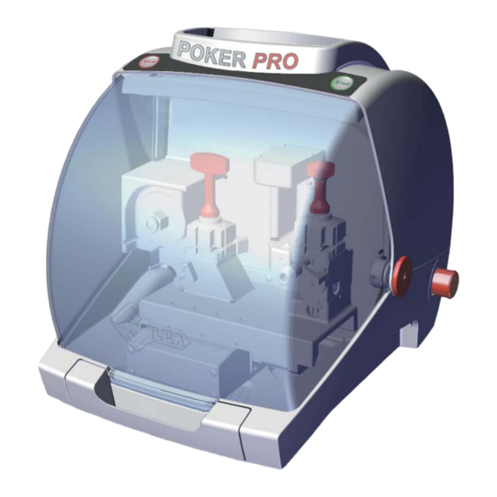
POKER PRO Operating manual 1 MACHINE DESCRIPTION POKER PRO is a professional automatic key-cutting machine. It is designed to cut fl at cylinder keys, vehicle keys and cruciform keys. Keys are read by an optical reader (laser). Keys are cut in a single operation. The key blank is cut directly as the original key is being read. -
Page 9: Main Operating Parts
POKER PRO Operating manual 1.1 MAIN OPERATING PARTS Fig. 3 - START button - STOP button - Safety shield - Lamp - Cover - Prismatic cutter - Optical reader - Tool compartment - Swarf collection tray - Clamp - cutter side... -
Page 10: Safety
Operating manual 1.2 SAFETY POKER PRO is entirely built in compliance to the Machine Directives. The operations for which it has been designed are easily carried out with no risk to the operator. The adoption of general safety precautions and observation of the instructions provided by the manufacturer in this manual eliminate all human error, unless deliberate. -
Page 11: Technical Data
Lp(A) = brass flat keys: 72.0 dB(A) steel flat keys: 74.5 dB(A) CLASS 1 LASER READER: • Maximum radiation with safety lock excluded: 230 μW • Wave length: 790,6 μm (invisible) • Classed to: EN 60825-1:2014 Copyright Silca 2019... -
Page 12: Accessories Provided
POKER PRO Operating manual 1.4 ACCESSORIES PROVIDED POKER PRO comes with a set of accessories for its operation and maintenance (tools, hex wrenches...) supplied in a special tool kit comprising: stop bar fuses 4 Amp.- delayed Allen keys set 1,5 ÷ 5 mm ø... -
Page 13: Handling
POKER PRO Operating manual 2 HANDLING The POKER PRO key-cutting machine is easy to handle and there are no special hazards involved in moving it. The packed machine can by carried manually by one person. 2.1 PACKING The packing for the POKER PRO key-cutting machine ensures safe handling of the machine and all its components. -
Page 14: Machine Installation And Preparation
3.1 CHECKING FOR DAMAGE POKER PRO is a solid compact machine and will not break if handling, unpacking and installation are carried out to the instructions in this manual. However, it is good practice to check that the machine has not been damaged. -
Page 15: Separate Parts
The machine packing also contains the following components, separately packed: 3.4.1 Power pack and lead Fig. 9 Fig. 10 Connect POKER PRO to the power pack (W) and connect the latter to the power supply with the power lead (W2). Fig. 11 3.4.2 Fixing bracket If the key-cutting machine is transported and used on a vehicle, e.g. -
Page 16: Quick Guide
POKER PRO Operating manual 3.4.3 Quick Guide It’s possible apply the Quick Guide sheet to the cover of the machine, using one of the supplied adhesive hooks (Z1) (Ch.1.4). Fig. 14 Fig. 15 3.5 WORK STATION DESCRIPTION One operator is enough to operate the machine, which has the following operating parts: •... -
Page 17: Clamps
POKER PRO Operating manual 4 CLAMPS Fig. 17 - Clamp CUTTER side Fig. 18 - Clamp OPTICAL READER side Fig. 19 The 4-sided clamp is used to secure keys fi rmly up against the back and on the profi le. -
Page 18: Clamps Rotation
POKER PRO Operating manual 4.1 CLAMPS ROTATION Positioning the correct side to be used is quick and easy. With the clamp jaws slightly open, turn the clamp by hand to position it as required, facilitated by a new special alignment system (Fig. 20). - Page 19 POKER PRO Operating manual • READER SIDE gauge Fig. 23 Fig. 24 Fig. 25 Fig. 26 Fig. 27 Fig. 28 Pull the gauge gently towards the operator (Fig. 23), turn clockwise by about 180° (Fig. 24) and release against the clamp (Fig. 25).
-
Page 20: Stop Positions (Key Stop)
POKER PRO Operating manual 4.3 STOP POSITIONS (KEY STOP HEAD STOP Fig. 29 - Stop 0 TIP STOP Fig. 30 : Stop 1 - 2 Use the bar provided (Ch.4.3) for keys without stops with the tip as a reference. -
Page 21: Use Of Pins
POKER PRO Operating manual 4.4 USE OF PINS For keys with narrow stems the pins must be placed between the bottom of the clamp and the back of the key so that the key protrudes suffi ciently out of the clamp and therefore can be properly read and cut. -
Page 22: Key Copying / Cutting
POKER PRO Operating manual 5 KEY COPYING / CUTTING Fig. 35 Fig. 36 1) Raise the safety shield (C). 2) Prepare the clamps on the most suitable side for the key to be cut (Ch.4.1). 3) Insert the ORIGINAL KEY into the clamp on the READER SIDE. - Page 23 POKER PRO Operating manual Fig. 37 - BLUE light Fig. 38 - GREEN light Copyright Silca 2019...
-
Page 24: Operation Or Error Indication Lights
Raise and lower the safety shield and press START • STOP button pressed with machine in motion to re-position the carriages and re-start the cycle. Contact Silca After-Sales Service. • Error X-Y axes motors The carriages do not move after pressing START FIXED and after 6 seconds the RED fi... -
Page 25: Cleaning
POKER PRO Operating manual 7 CLEANING • Keep the operational parts of the machine as clean as possible by brushing away the chippings in areas where they accumulate during cutting operations. • Under no circumstances should compressed air be used to clear the work zone of chippings as this will blow them onto the moving parts. -
Page 26: Maintenance
ATTENTION: for repairs or replacement of parts for maintenance, the ‘CE’ mark is guaranteed only if original spare parts provided by the manufacturer are used. The POKER PRO key-cutting machine does not need special maintenance, but it is good practice to check and if necessary replace parts subject to wear: cutter, clamps. -
Page 27: Replacing The Cutter
POKER PRO Operating manual 8.3 REPLACING THE CUTTER 1) Turn off the key-cutting machine and unplug. 2) Raise the safety shield. 3) Use a 19mm wrench (provided) to hold still the hex washer (F1) (Fig. 41). 4) Use a 13mm wrench (provided) to LOOSEN THE NUT (F2) CLOCKWISE (Fig. 42). ATTENTION: THE THREAD IS LEFT-HANDED. -
Page 28: Access To Rear Compartment
Fuses must always be replaced with the same amperage and type (rapid or delayed), as indicated in this manual. POKER PRO has 1 fuse: 4 Amps delayed Protects the cutter motor and its electronic controls (24 d.c.) Follow the instructions below to check and, if necessary, replace: 1) Turn off the key-cutting machine and unplug. -
Page 29: Replacing The Top Cover / Keypad
POKER PRO Operating manual 8.6 REPLACING THE TOP COVER / KEYPAD 1) Turn off the key-cutting machine and unplug. 2) Access the rear compartment (Ch.8.4). 3) Disconnect the keypad fl at cable (Fig. 47). 4) Remove the screws (E2) and washers (E3) (Fig. 48). -
Page 30: Disposal
POKER PRO Operating manual 9 DISPOSAL For correct disposal please refer to current standards. INFORMATION FOR USERS OF PROFESSIONAL EQUIPMENT From “Actuation of Directive 2012/19/EU regarding Waste Electrical and Electronic Equipment (WEEE)” The symbol of a crossed waste bin found on equipment or its packing indicates that at the end of the product’s useful life it must be collected separately from other waste so that it can be properly treated and recycled. -
Page 31: Assistance
10.1 HOW TO REQUEST SERVICE The guarantee attached to the key-cutting machines ensures free repairs or replacements of faulty parts within 24 months of purchase. All other service calls must be arranged by the customer with Silca or with a Silca service center. - Page 32 POKER PRO Operating manual Copyright Silca 2019...
-
Page 33: Electrical Diagrams
POKER PRO Operating manual 11 ELECTRICAL DIAGRAMS J13 X axis motor J9 optic reader J12 X axis sensor J14 Y axis motor J15 Y axis sensor J7 cutter motor + micro carter Copyright Silca 2019... - Page 34 POKER PRO Operating manual OPTIC READER MOTHER BOARDJ9 Laser receiver Laser transmitter STEP MOTOR X AXIS light blue green MOTHER BOARD J13 yellow STEP MOTOR Y AXIS white/red green MOTHER BOARD J14 white/green X AXIS SENSOR yellow brown black black...
- Page 35 POKER PRO Operating manual MICRO CARTER MOTHER BOARD J22 WHITE LED LAMP black MOTHER BOARD J23 3 COLORS LED LAMP RED LIGHT orange white green brown MOTHER BOARD J8 blue grey GREEN LIGHT BLUE LIGHT Copyright Silca 2019...
- Page 36 POKER PRO Operating manual GAUGE SENSOR yellow brown black black MOTHER BOARD J10 light blue light blue CUTTER MOTOR + MICRO CARTER Cutter motor MOTHER BOARD J7 black black black Micro carter POWER SUPPLY +24V +24V MOTHER BOARD J4 black...
- Page 37 POKER PRO Operating manual Power feeder Alimentatore Speisegerat Alimentateur Alimentador Alimentador Voedingseenheid +24V +24V +24V +24V +24V +24V +24V Cutter motor Motore fresa Motor-Fräser Moteur fraise Motor fresa Motor fresa Freesmotor + micro carter + micro carter + Mikro-Carter + micro carter...
- Page 38 EN 61000-3-2:2014 EN 61000-3-3:2013 EN ISO 13849-1:2015 EN ISO 13849-2:2012 EN 62471:2008 IEC TR 62778:2014 EN 62233:2008 EN 60825-1:2014 EN 62368-1:2014 + EC 2015 + A11:2017 Silca S.p.A. R&D Division is authorized to create a Technical File. VITTORIO VENETO, 06/06/2019...
Need help?
Do you have a question about the POKER PRO and is the answer not in the manual?
Questions and answers