Table of Contents
Advertisement
Quick Links
Advertisement
Table of Contents

Subscribe to Our Youtube Channel
Related Manuals for Silca Unocode PRO


Summary of Contents for Silca Unocode PRO
- Page 1 FLAT STEEL Operating Manual Original instructions D446068XA vers. 3.0...
- Page 2 This manual is written by SILCA S.p.A. All rights reserved. No part of this publication may be reproduced or used in any form or by any means (photocopying, microfilm or other) without the written permission of SILCA S.p.A. Edition: September 2017 Printed in Vittorio Veneto by SILCA S.p.A.
-
Page 3: Table Of Contents
ONTACT ............. 15 ITTING THE CLAMP TO THE MACHINE ......................15 UTTER ................15 HANGING THE CUTTER UNOCODE PRO version UTP ..............16 OPERATING GUIDE ..................17 ..................17 NITIAL OPERATIONS ..........18 ACHINE KEYBOARD AND FUNCTION BUTTONS .................. 20 OPY FROM RIGINAL ................ - Page 4 6.11.2 UTP SETTINGS ........................62 6.11.3 M 2/4] ....................63 ACHINE OPTIONS PAGE 6.11.4 M 3/4] ..................... 63 ACHINE OPTIONS PAGE 6.11.5 M 4/4] ..................... 64 ACHINE OPTIONS PAGE 6.12 ENABLING ....................65 6.13 M ....................66 ESSAGES 6.13.1 A ......................
-
Page 5: Reference Guide
UNOCODE PRO REFERENCE GUIDE This manual has been produced to serve as a guide for users of the UNOCODE PRO electronic key-cutting machine. Read it carefully; it is essential if you wish to operate your machine safely and efficiently. ONSULTATION... -
Page 6: General
If the key-cutting machine is used differently or for purposes different from those described in this manual, the customer will forego any rights he may have over Silca S.p.A. Furthermore, unforeseen danger to the operator or any third parties may arise from incorrect use of the machine. - Page 7 The machine is provided with an identification label which includes the machine’s serial number (fig. 3). Fig. 3 (*) see Ch.9 "DISPOSAL", page 86. GRAPHICS ON THE UNOCODE PRO KEY-CUTTING MACHINE Do not clean with Obligation to read Obligatory use...
-
Page 8: Machine Description
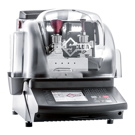
Operating manual - English MACHINE DESCRIPTION UNOCODE PRO is an electronic machine operating on two axes (3rd axis optional) with controlled movement. Accu- rately studied, it adds a high degree of cutting precision to operating speed and ease of use. -
Page 9: Safety
The cutter motor is protected against overheating by a cut-out switch (located inside the motor) that will automatically stop the motor if it reaches a certain temperature. Should the switch activate: 1) turn the machine off and disconnect the power supply cable. 2) contact Silca’s Technical Assistance Dept. Copyright Silca 2017... -
Page 10: Main Working Parts
UNOCODE PRO Operating manual - English 1.3 M AIN WORKING PARTS Fig. 6 - master switch - keyboard C - display D - clamp - cutter side D1 - clamp - optical reader - clamp knob E1 - optical reader clamp knob... -
Page 11: Technical Data
Tool speed: Unocode PRO: 50Hz: 1700 rpm (+/- 10%) 60Hz: 2040 rpm Unocode PRO Flat Steel: 50Hz: 2340 rpm (+/- 10%) 60Hz: 2800 rpm Movements: on 2 axes with ball screws activated by step motors, on rectified roller guides. Possibility to add a 3rd axis to activate the optional tilting and rotating clamps. -
Page 12: Accessories Provided
UNOCODE PRO Operating manual - English 1.5 A CCESSORIES PROVIDED UNOCODE PRO comes with a set of accessories for its operation and maintenance (tools, hex wrenches, fuses) supplied in a special tool kit comprising: tool kit 10 mm spanner Z1 template... -
Page 13: Transport
ACKING The packing for UNOCODE PRO is designed to ensure safe transportation and to protect the machine and all its parts. It comprises a pallet base (b) to which the machine is attached, and a cardboard box as a cover (a). -
Page 14: Unpacking
2.3 M ACHINE HANDLING When the UNOCODE PRO has been unpacked, place it directly on its workbench; this operation should be carried out by at least two people. Take care to lift the machine firmly holding the base, and no other part. -
Page 15: Machine Installation And Preparation
HECKING FOR DAMAGE UNOCODE PRO is solid and compact and will not normally damage if transport, unpacking and installation have all been carried out according to the instructions in this manual. However, it is always advisable to check that the machine has not suffered any damage. -
Page 16: "Set Up" And Use Of The Machine
UNOCODE PRO Operating manual - English “SET UP” AND USE OF THE MACHINE 4.1 U SE OF THE CLAMP V100 R100 Clamp - cutter side Clamp - Optic Reader side Fig. 10 The four-sided clamp ensures excellent grip on the keys placed on their back or profile sides (fig. 11). - Page 17 Operating manual - English UNOCODE PRO ATTENTION: the knobs are gauged so that they do not exert too much pressure for closing (if pressure is too high they only idle), which would damage the key and the parts of the clamp (including the knob).
-
Page 18: Cutting By Electric Contact
Cuts cannot be repeated on the same side of the key when electric contact cutting is used. All data cards provided by Silca are in the machine’s memory. The cards are enabled or disabled for code cutting by electric contact at Silca’s discretion. -
Page 19: Fitting The Clamp To The Machine
Operating manual - English UNOCODE PRO 4.3 F ITTING THE CLAMP TO THE MACHINE To remove the clamp unit: - loosen the grub screw (D2) (fig. 17) and slide the clamp out of the dovetail guide. To install the clamp unit on the machine: - slide the clamp into the dovetail guide, pushing it all the way in, then secure it by tightening the grub screw (D2). -
Page 20: Unocode Pro Version Utp
• When the UTP package has expired 30 days of Extratoken are available before the key-cutting function is blocked. (Ch 6.11.2 "UTP SETTINGS"). • After purchasing a new UTP package download it from the Internet by means of the “Silca Remote Service” program (SRS) (Ch.6.8.1 "DOWNLOAD THE UTP PACKAGE"). -
Page 21: Operating Guide
When the UNOCODE PRO is used with a Personal Computer, the operating guide does not change its displays logic, with the exception of all the screens that are rendered unnecessary. -
Page 22: Machine Keyboard And Function Buttons
UNOCODE PRO Operating manual - English 6.2 M ACHINE KEYBOARD AND FUNCTION BUTTONS Fig. 20 The MENU key is used to view the list of main functions MENU key: is always active from any of the windows. Function keys: select the on-screen options... - Page 23 • CodeMaker (not enabled on the UTP version) • Gauging • Maintenance • Options • Enabling UNOCODE PRO UNOCODE PRO UTP Press the MENU key repeatedly to view the list of icons relating to the main functions of the machine program. Copyright Silca 2017...
-
Page 24: Copy From Original
UNOCODE PRO Operating manual - English 6.3 C OPY FROM RIGINAL In the initial screen press F1 to use the function. This function is used to make a direct copy from the key, without further stages. The “Copy from Original” window shows certain data and icons: •... -
Page 25: Copy With Adjustments
Operating manual - English UNOCODE PRO First the display will show: and then: - Press STOP to confirm the end of the operation. - Press ENTER if you wish to cut other keys. 6.4 C OPY WITH ADJUSTMENTS In this mode an original key is copied in 3 stages: •... - Page 26 UNOCODE PRO Operating manual - English Note: after placing the original key in the r/h clamp, remember to lower the gauge. If this is not done, when reading starts the machine will stop and show the following message on the display: In this case lower the gauge and press START to continue.
- Page 27 Operating manual - English UNOCODE PRO Press ENTER to view the “new” key with the adjustments made.The display will show: - a black outline of the original key (key read). - a blue outline of the key to be cut, with the adjustments made.
-
Page 28: Copy From Cutting Card
From the initial screen press F2 to use the function. One part of the machine’s internal memory is used as a cutting card archive. A cutting card is a database of “Spaces”, “Depths” and cutting angles for all the keys Silca considers can be taken into consideration. - Page 29 • CODEMAKER cutting cards: Note: on the UTP version the Search for cutting cards created with Codemaker (optional program) is run only through the Silca Key Program. Customized cards created using CODE MAKER on the machine. • Press F3 to view a list of CodeMaker cards.
- Page 30 UNOCODE PRO Operating manual - English Card No Symbols associated to cutting depths Clamp to use Adapter if applicable Number of cuts per side for current key Cutting Symbols allowed Fig. 21 • Press F1 to consult the cutting parameters on the card.
- Page 31 Operating manual - English UNOCODE PRO • Press F1 to set positive values (+). • Press F2 to set negative values (-). • Press F3 to cancel the adjustments made. Adjustments possible for depth (-30 to +30 hundredths of a mm): - one value (positive or negative) raises or lowers all cuts.
- Page 32 UNOCODE PRO Operating manual - English • Decoding by data card Press F1 to decode the selected data card. Decoding Figura 22 • Press ENTER to continue. 1) Press START to begin the DECODING operation. Note: the decoding operation is not available for all data cards.
- Page 33 UNOCODE PRO Modify cutting method • By pressing F1 it is possible to view the cutting method set by Silca for the card and to modify it when possible (Ch.6.5.1, page 34). Note: the editing can be saved as User Parameters.
- Page 34 Note: the maximum variation allowed refers to the value set in the OPTIONS menu (pages 2/4), item “Speed variation limits. F1: to increase the percentage value F2: to decrease the percentage value F3: to reset the Silca default values for carriage speed Note: the editing can be saved as User Parameters. Copyright Silca 2017...
- Page 35 Operating manual - English UNOCODE PRO 2) proceed with cutting the first side by pressing the START key. 3) Turn the key and cut the second side if the key is symmetrical, as in this case. Press START. When the last side of the last key has been cut, the screen shows:...
- Page 36 UNOCODE PRO Operating manual - English • Saving Data Card in Favourites Menu Press F3 to save in the Favourites Menu: - a SILCA data card - a USER data card - a CODEMAKER data card • Press ENTER to continue.
- Page 37 UNOCODE PRO • Copy SILCA Data Card onto CODEMAKER Note: the “Copy Silca cutting card in Codemaker” function on the UTP version is not enabled. Press F2 to copy a SILCA data card on the CODEMAKER and change some of the parameters.
-
Page 38: Special Cases
This happens when the cutting depths are not compatible in the order the user entered the possible cuts. Example: After entering the cutting combination the Silca software calculates the validity of the data. If there is inconsistency, when the ENTER key... - Page 39 UNOCODE PRO • Changing the Types of Cut All the data cards provided by Silca have the type of cut pre-set according to the original parameters. The types of cut possible with UNOCODE PRO are: Normal, Flat, Laser and Vertical.
-
Page 40: Limited Access To Data (Protected Systems)
Note: replace the cutter according to the instructions in Ch. 8.3, page 75. • Use of Adaptors Some of the data cards provided by Silca may show a new parameter (Adapt.:B...) which indicates the type of accessory that is needed to cut the key in question (fig. 21, page 26). - Page 41 Operating manual - English UNOCODE PRO Once obtained, enter the password on the Password line, as shown in the example given. If the correct password has been entered, the screen shows: The password can be saved so that it need not be entered whenever the protected data card is used, or not saved so that access is limited only to the person in possession of the password.
-
Page 42: Pc Queue
Taken for granted that the user is in possession of some Silca software, the following are the possibilities available. The ‘Silca Code Program’ makes it possible to carry out searches by code for cutting data and to store the information in a special work queue (or file). - Page 43 Press ENTER to continue, the display will show: • Press F1 to view the cutting method set up by Silca for the card in question. • Press F2 to enable or disable the electrical contact function for reading the key blank measurements.
- Page 44 UNOCODE PRO Operating manual - English • Press F3 to vary the setting for the value of the key blank measurements. Note: when electrical contact is used it is advisable to set key blank measurements that are the same as those of the key to be cut.
-
Page 45: Code Maker
• Delete card created (press F3 to start) • Copy a user-created card (press F1 to start) • Copy a Silca data card onto CODEMAKER (press F2 to start) NOTE: Creating of new cards is allowed for two key types:... - Page 46 UNOCODE PRO Operating manual - English Step 3 Enter the depth symbols (numbers or letters) and associate them to the required cutting depth. Press ENTER to confirm the value and go from one field to another. All measurements are expressed in hundredths of a millimetre or inches, according to the settings in the machine Options (Ch.6.11, page 61)
- Page 47 Operating manual - English UNOCODE PRO • Editing a card created by Code Maker This function is used to edit a card previously created by Code Maker. Use the arrow keys to select the card to be edited. - Press F2 for the editing controls.
-
Page 48: 6.8 Utp Update And Clock Synchronisation
Note: UTP function is NOT enabled on Unocode PRO FLAT STEEL An internet connection and the Silca Remote Service (SRS) program are required. If necessary the Silca Remote Service program can be downloaded from the Silca website www.silca.biz. Select the menu: Products -> Silca Key Programs ->... -
Page 49: Synchronise Machine Date/Time (Utp Version Only)
Operating manual - English UNOCODE PRO 6.8.2 SYNCHRONISE MACHINE DATE/TIME (UTP VERSION ONLY) Note: this operation is necessary only when the machine mother board battery has been replaced. Note: do not turn the machine off during data transfer. The machine must be on. -
Page 50: 6.9 Gauging
UNOCODE PRO Operating manual - English 6.9 GAUGING The following components on the machine have a specific ‘self-setting’ procedure with the use of regulating templates (Ch.1.5 "Accessories provided", page 8): - CLAMPS - CUTTERS ADAPTERS provided as optionals do not require calibrating. However, if necessary adjustments can be made to the cutting data, according to the procedures described in Ch.6.4 "Copy with adjustments", page 21. -
Page 51: Calibrate Jaws
Press ENTER, the display will show: Make sure the U01W standard prismatic cutter is installed. ATTENTION: If the original Silca U01W cutter is replaced with one that is NOT original or has been sharpened, it will be necessary to repeat clamp gauging and also gauge all the optional cutters. - Page 52 UNOCODE PRO Operating manual - English Press ENTER, the display will show: - Fit the test key blank (Z3 template) into side A of the left-hand clamp (Stop 0). Fig. 27 - Lower the safety shield and press START. When cutting is complete...
- Page 53 Operating manual - English UNOCODE PRO Press ENTER, the display will show: As the Z20 template is already on the reading clamp, just press START. After an initial message of “Reading” the display will show (example): Note: discrepancies in X of +/-0.03 mm from theoretical measurements can be considered normal.
- Page 54 UNOCODE PRO Operating manual - English The Y measurement read should be the same as the theoretical one (value = 500 in brackets). If not, proceed as follows: • For a Y value lower than 500, loosen the grub screw (P3) and use a hex.
-
Page 55: Calibrate Cutters
• If the original Silca U01W cutter is replaced with another Silca original, there is no need to repeat clamp gauging. • If the original Silca U01W cutter is replaced with one that is NOT original or has been sharpened, it will be necessary to repeat clamp gauging and also gauge all the optional cutters. -
Page 56: Calibrate Adapters
UNOCODE PRO Operating manual - English 6.9.3 CALIBRATE ADAPTERS From the Gauging menu press F3 to enable the Adapter gauging function. Use the up/down arrow keys to select the adapter to be gauged and press ENTER. The display will show: •... -
Page 57: 6.10 Maintenance
0 the reader is inactive. Contact Silca after-sales service. • If the value to the left is higher than 90 clean the reader glass slide with a clean cloth. • If the value remains over 90 (or lower 50) contact Silca after- sales Service. 6.10.2 MOTOR TESTS... -
Page 58: Digital Outlets Tests
- In the case of the cutting side or reading lamp, the one in question will illuminate momentarily. Note: if this is not so, contact Silca’s Technical Assistance Dept. This test (Exit...) can be carried out only when an automatic feeder (or other optional component) is installed on the machine. -
Page 59: Serial Port
Fit the special (Z4) serial test connector (accessories provided) to the machine’s serial port. Press START and check that the machine’s display indicates OFF to Note: if the ON/OFF transition is not made, contact Silca’s Technical Assistance Dept. 6.10.8 MACHINE ZERO POINTS With the use of regulating templates (Ch.1.5 "Accessories provided", page 8) the machine provides a ‘self-setting’... - Page 60 UNOCODE PRO Operating manual - English Press ENTER to continue, the display shows: Read the instructions on the display and fit the Z20 template into the cutter side of the clamp, with Stop 0 as the reference. Fig. 32 Lower the gauge and press ENTER to continue.
- Page 61 Operating manual - English UNOCODE PRO Press START, the display will show: Press ENTER to confirm, only if the previous parameters were ON (***). Press STOP to cancel the operation and not confirm the adjustments made (if there is one value or more on OFF). The previous values remain valid (already in the machine’s memory).
-
Page 62: Photocells And Sensors Regulation
UNOCODE PRO Operating manual - English 6.10.9 PHOTOCELLS AND SENSORS REGULATION PRELIMINARY OPERATIONS 1) turn the machine off and unplug it from its power supply cable. 2) remove the back panel (Ch.8.8). 3) loosen the (G1) and (G2) grub screws that secure the X axis photocell disk (fig. 34). - Page 63 Operating manual - English UNOCODE PRO Y axis photocell: • manually turn the Y axis disk (fig. 36) up until the display’s description changes from OFF to ON. • use the provided allen key to tighten the (G3) grub screw.
- Page 64 UNOCODE PRO Operating manual - English Y axis sensor Figura 37 bottomview ATTENTION: if it is necessary to work close to this area with the machine turned on (e.g. to regulate the X axis sensor) take great care not to touch any components on the machine’s electronic boards as it is...
-
Page 65: 6.11 Options
There are 4 machine option windows that are selected by pressing F4. ATTENTION: Hold down F4 to take the machine back to its initial state (with the original parameters set by Silca). Machine Parameters/Options that can be forced from the original factory setting:... -
Page 66: Utp Settings
30 days (Extratoken) in which to purchase a UTP package. At the end of the 30 days the machine can no longer be used to cut keys (it is operative for decoding only). To continue using all the machine functions contact a Silca distributor to purchase another UTP package. -
Page 67: Machine Options
The set speed is that for ideal conditions, but the operator can change it from a minimum of 1000 to a maximum of 5000 (Silca configuration: 4000 UC Pro - 5000 UC Pro Flat Steel). Cutting speed: corresponds to the speed at which the carriage advances during key-cutting. -
Page 68: Machine Options
UNOCODE PRO Operating manual - English 6.11.5 MACHINE OPTIONS [PAGE 4/4] The display shows: Clock management Date and time format: use the arrow keys (rh/lh) to select the DATE format (DD/MM/YY by default, or MM/DD/YY or YY/MM/DD) and TIME format (0 - 24 by default or am - pm) required, then press ENTER to confirm. -
Page 69: 6.12 Enabling
Operating manual - English UNOCODE PRO 6.12 ENABLING From the screen, press MENU and/or F4 to enable the function. This display shows all the protected systems enabled and allows them to be protected again, if necessary. E.g.: In this case a single protected card has been previously enabled. -
Page 70: Messages
UNOCODE PRO Operating manual - English 6.13 M ESSAGES 6.13.1 ATTENTION MESSAGES Data card not available! • The entered data card number is not available in the machine’s data base. Non-feasible combination! • The entered cuts cannot be carried out (see Ch.6.5.1, page 34). - Page 71 Resetting of original machine data Confirm operation? No=STOP Yes=ENTER • This message appears if you wish to reset the machine on the initial settings, i.e. with the default parameters set up by Silca (see Ch.6.11, page 61). Copyright Silca 2017...
-
Page 72: Error Messages
Machine ID is set. Select menu 6.12 "ENABLING"and check that the Machine ID is different from 0. To set Machine ID ask for a Software update valid for your machine and install with the SILCA WinTransfer Program or SILCA Code Program. -
Page 73: Alarm Messages
Operating manual - English UNOCODE PRO 6.13.3 ALARM MESSAGES ALARM 1 OPTICAL READER E R R O R See operating manual • This message indicates that there is a fault in the optical reader or that something is obstructing its laser beam before starting the reading or decoding cycle. -
Page 74: Codemaker Messages
UNOCODE PRO Operating manual - English 6.13.4 CODEMAKER MESSAGES Key Blank dimension out of range! Limit values: • Appears when the depth value exceeds the key blank measurement assigned to the key. Cutting angle out of range! Limit values: • Appears when the set angle is higher or lower than the limit allowed by the cutter in use. - Page 75 Operating manual - English UNOCODE PRO The cut depth is not compatible with cutting edge of the cutter. See operating manual. • Appears when the cutting depth would not allow the cutter to move sideways. The cut depth exceeds the safety limit of the selected jaw side! See operating manual.
-
Page 76: Cleaning
UNOCODE PRO Operating manual - English CLEANING • Keep the operational parts of the machine as clean as possible by brushing away the chippings in areas where they accumulate during cutting operations. • Under no circumstances must compressed air be used to clear the work zone of chippings as this will blow them onto the moving parts. -
Page 77: Maintenance
Although the UNOCODE PRO key-cutting machine does not require special maintenance, it is advisable to check and, if necessary, replace the parts subject to wear and electric/electronic parts (fuses, circuit boards, etc.) in the event of faulty operation. - Page 78 UNOCODE PRO Operating manual - English FAULT PROBABLE CAUSE Optical reader not working a) glass lent on the optical reader is dirty b) wiring between optical reader and the electronic control board is not seeded properly c) defective optical reader...
-
Page 79: Maintenance Operations
Operating manual - English UNOCODE PRO 8.2 M AINTENANCE OPERATIONS • Cutter replacement • Belt replacement and tension adjustment • Fuse check and replacement • Electronic circuit board replacement • Keyboard/display replacement • Access to back compartment • Access to bottom compartment •... -
Page 80: Belt Replacement And Tension Adjustment
UNOCODE PRO Operating manual - English 8.4 B ELT REPLACEMENT AND TENSION ADJUSTMENT To replace the belt, proceed as follows: 1) turn the machine off and unplug it. 2) remove the back panel (Ch.8.8, page 80). 3) remove the bottom panel (Ch.8.9, page 80). -
Page 81: Checking And / Or Replacing Fuses
Fuses must always be replaced with the same amperage and type (rapid or delayed), as indicated in this manual. There are 6 fuses in the UNOCODE PRO. • 2 fuses: 4 Amps rapid (230V) 5 Amps rapid (100V) located next to the power socket on the back of the machine, next to the main switch (fig. -
Page 82: Electronic Circuit Board Replacement
UNOCODE PRO Operating manual - English 8.6 E LECTRONIC CIRCUIT BOARD REPLACEMENT Proceed as follows: 1) turn the machine off and unplug it from its power supply cable. 2) remove the bottom panel (ch.8.9, page 80). 3) disconnect all cable connectors from the electronic circuit board (fig. 49). -
Page 83: Keyboard / Display Replacement
Operating manual - English UNOCODE PRO 8.7 K EYBOARD DISPLAY REPLACEMENT 1) turn the machine off and unplug it from its power supply cable. 2) remove the display’s support, by unscrewing the 2 (B1) fixing screws (fig. 51 and fig. 52). -
Page 84: Access To Back Compartment
UNOCODE PRO Operating manual - English 8.8 A CCESS TO BACK COMPARTMENT To gain access to the back compartment, proceed as follows: 1) turn the machine off and unplug it from its power supply cable. 2) remove the vacuum system’s connector (U2) (fig. 54). -
Page 85: Sensor Replacement
Operating manual - English UNOCODE PRO 8.10 S ENSOR REPLACEMENT AXIS SENSOR REPLACEMENT 1) turn the machine off and unplug it from its power supply cable. 2) remove the bottom panel (Ch.8.9 "Access to bottom compartment"). 3) disconnect the X axis sensor’s connector from the electronic circuit board (fig. 56). - Page 86 UNOCODE PRO Operating manual - English AXIS SENSOR REPLACEMENT 1) turn the machine off and unplug it from its power supply cable. 2) raise the protective shield. 3) disconnect the (J1) Y axis cable from the carriage (fig. 59). 4) remove the Y axis carriage cover by unscrewing the 3 (B5) locking screws and pull the cover in the direction shown in fig.
-
Page 87: Photocell Replacement
Operating manual - English UNOCODE PRO 8.11 P HOTOCELL REPLACEMENT EPLACING THE AXIS PHOTOCELL 1) turn the machine off and unplug it from its power supply cable. 2) remove the back panel (Ch.8.8 "Access to back compartment"). 3) unscrew the 2 (G) screws that secure the photocell card and remove. -
Page 88: Brush Replacement
UNOCODE PRO Operating manual - English 8.12 B RUSH REPLACEMENT 1) Open the rear compartment (ch.8.8, page 80). 2) Unscrew the two brush caps (M4) (fig. 64), remove and fit two new brushes. 3) Replace the two caps (M4). 4) Close the rear compartment. -
Page 89: Win -Transfer Program And User Data Backup /Restore
- continue with the gauging of remaining jaws used. At this point the machine is set up and ready for operation. • SILCA update for the program or machine data 1) Install the WinTransfer Program update on your personal computer, following the instructions in the program. 8.14.1... -
Page 90: Disposal
UNOCODE PRO Operating manual - English DISPOSAL For correct disposal please refer to current standards. INFORMATION FOR USERS OF PROFESSIONAL EQUIPMENT From "Actuation of Directive 2012/19/EU regarding Waste Electrical and Electronic Equipment (WEEE)" The symbol of a crossed waste bin found on equipment or its packing indicates that at the end of the product’s useful life it must be collected separately from other waste so that it can be properly treated and recycled. -
Page 91: 10 Assistance
OW TO REQUEST SERVICE The guarantee attached to the UNOCODE PRO ensures free repairs or replacements of faulty parts within 24 months of the date of purchase. All other service calls must be arranged by the customer with Silca or specialized Silca service centres. - Page 93 UNOCODE PRO SCHEMI ELETTRICI - ELECTRICAL DIAGRAMS - ELEKTRISCHE SCHALTPLANE SCHEMAS ELECTRIQUE - ESQUEMAS ALAMBRICOS - ESQUEMAS ELÉCTRICOS ELEKTRISCHE TEKENINGEN 6.3A J 16 1 24 Vac 24 Vac 18 Vac 18 Vac Copyright Silca 2017...
- Page 94 UNOCODE PRO ROSSO ROUGE ROJO BIANCO WHITE BLANC BLANCO WEISS ARANCIO ORANGE ORANGE ANARANJADO ORANGE NERO BLACK NOIR NEGRO SCHWARZ MARRONE BROWN BRUN MARRON +24V BRAUN INSX AZZURRO BLUE +12V AZUR INFX AZUL BLAU INFX +12V Copyright Silca 2017...
- Page 95 UNOCODE PRO ROSSO ROUGE ROJO GIALLO YELLOW JAUNE AMARILLO GLEB ARANCIO ORANGE ORANGE ANARANJADO ORANGE NERO BLACK NOIR NEGRO +24V SCHWARZ INSY MARRONE BROWN BRUN +12V MARRON BRAUN INFY AZZURRO BLUE AZUR AZUL INSY BLAU INFY BIANCO +12V WHITE BLANC...
- Page 96 UNOCODE PRO SCHEDA RS232/USB CARD RS232/USB FICHE RS232/USB FICHA RS232/USB KARTE RS232/USB INAUX 3 26 INAUX 1 25 13 INAUX 1 INAUX 2 24 25 INAUX 2 3 23 12 OUT ALIMENTATORE AUTOMATICO 2 22 24 OUT AUTOMATIC FEEDER OUT 1 21...
- Page 97 UNOCODE PRO ELETTROVALVOLA ASPIRAZIONE VACUUM SOLENOID VALVE 24V/1.5A ELECTROVANNE ASPIRATION ELECTROVALVULA ASPIRADOR ELEKTROVENTIL SPANEABSAUGANLAGE CONTATTO ELETTRICO CHIAVE ELECTRIC CONTACT CONTACT ELECTRIQUE INPKEY CONTACTO ELECTRICO ELEKTRISCH KONTAKT MICROINTERRUTTORE CARTER (IN7) MICROSWITCH SHIELD MICRO-INTERRUPTEUR ECRAN (IN8) MICROINTERRUPTOR CARTER MIKROSCHALTER SCHUTZ LASER ENA-CHARGE...
- Page 98 UNOCODE PRO LAMPADA LED LED LAMPE LAMPE LED LAMPARA LED LAMPE LED Copyright Silca 2017...
- Page 99 European Union DIRECTIVE 2006/95/CE (Low Voltage) and with the EN 60950 – 1 EN 60825 – 1 Standards Claudio Tomasella of the Silca S.p.A. Research & Development Division is authorized to create a Technical File. General Manager Basic Production Center...
- Page 100 Phone: +39 0438 9136 Fax +39 0438 913800 E-mail: silca@silca.it www.silca.biz India United Kingdom MINDA SILCA Engineering Ltd. SILCA Ltd. Plot no.37, Toy City, Unit 6 Lloyds Court - Manor Royal GREATER NOIDA (U.P.) - 201308 CRAWLEY RH10 9QU Phone: +91 9871397630/31...
Need help?
Do you have a question about the Unocode PRO and is the answer not in the manual?
Questions and answers