
Related Manuals for Silca UC 199


Summary of Contents for Silca UC 199
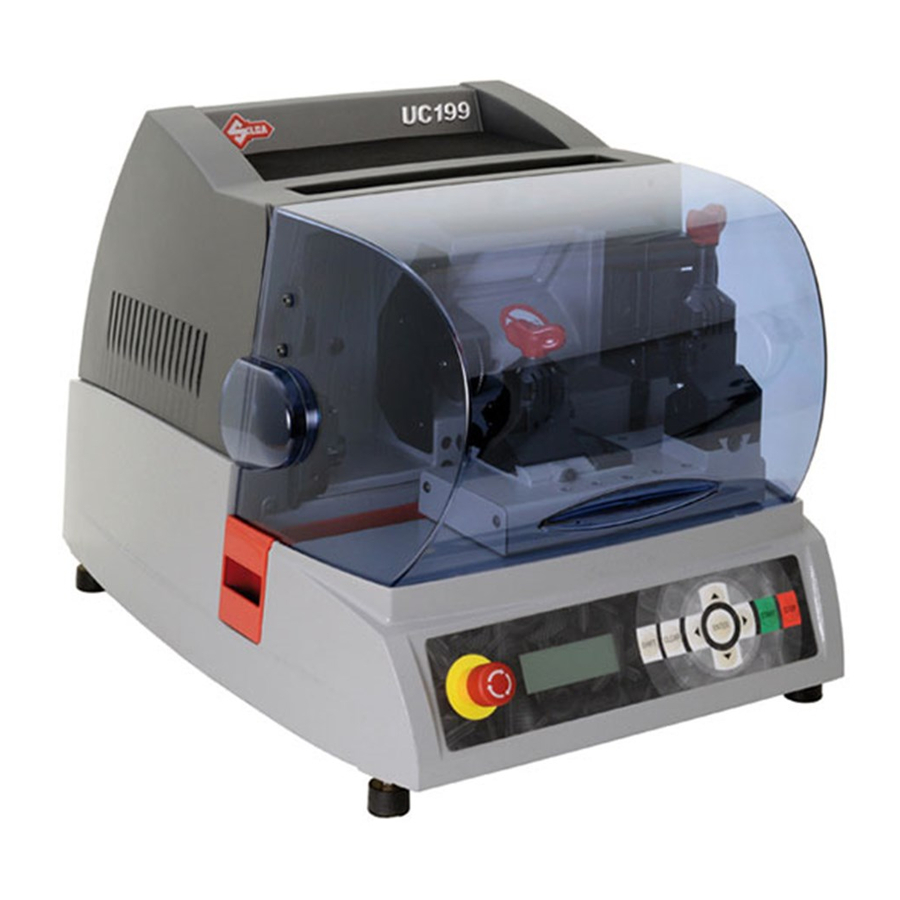
- Page 1 UC199 UC199 UC199 Japan UC199 Japan Operating Manual Original Instructions D441737XA vers. 1.0...
- Page 2 (c) 2012 SILCA S.p.a. – Vittorio Veneto This manual has been drawn up by SILCA S.p.a. All rights reserved. No part of this publication can be reproduced or circulated by any means whatsoever (photocopies, microfilm or other) without the consent of SILCA S.p.a.
-
Page 3: Table Of Contents
INDICE USE OF THE MANUAL ........................1 GENERAL WARNINGS ........................3 1 MACHINE DESCRIPTION ........................4 1.1 Main characteristics ........................5 1.2 Safety ............................6 1.3 Main working parts (Standard) ....................7 1.4 Main working parts - with OPTIONAL “Loader Unit” ..............8 1.5 Technical Data ..........................9 1.6 Accessories Provided .......................10 2 TRANSPORT ............................11 2.1 Packing .............................11... - Page 4 5.10 Machine message .........................65 5.10.1 Error message.........................65 5.10.2 ATTENTION messages ....................65 5.10.3 Alarm Messages ......................67 6 CLEANING ............................69 7 MAINTENANCE ..........................70 7.1 Trouble shooting ........................70 7.2 Maintenace operations ......................72 7.3 Access to the top compartment ....................72 7.4 Access to the bottom compartment ..................73 7.5 Cutter replacement ........................73 7.6 Belt replacement and tension adjustment .................74 7.7 Replacement of the jaws on the automatic optional clamp - OPTIONAL ........75...
-
Page 5: Use Of The Manual
The warranty card attached to the machine covers free repairs or replacement of faulty parts for 24 months from the date of purchase*. All operations must be agreed by the user with Silca or the Service Centre. * Damage caused by negligence or wrong use of the machine by the user will null the warranty. - Page 6 7) Cuts 2) Neck 4) Stem 6) Back 8) Diameter GRAPHICS IN THE USER’S MANUAL Obligation to read Pay attention the manual GRAPHICS ON THE UC199 KEY-CUTTING MACHINE Obligatory use of (ch.1.2) Laser warning labels safety goggles Copyright Silca 2012...
-
Page 7: General Warnings
To guarantee maintaining these results over time, please follow the instructions below: • Observe the procedures described in this manual; • Always use Original Silca Tools as they are designed to make the best of UC199 and provide quality key- cutting; • Use Silca key blanks, made with top quality materials;... -
Page 8: Machine Description
UC199 can operate by: • Reading a key with a laser reader and duplicating it • Connecting to a PC and using Silca software Fig. 3 UC199 is used to cut the following types of keys: only with UC199 JAPAN Fig. -
Page 9: Main Characteristics
(with jaws A); max.9 mm (with jaws B) Key head width: *max. 28 mm ATTENTION: only for keys with cuts on 1 side and key stop [not keys with plastic heads (except for SWING and SILKY), not cruciform keys or keys with tip stops]. Copyright Silca 2012... -
Page 10: Safety
The cutter motor is protected against overheating by a cut-out switch (located inside the motor) that will automatically stop the motor if it reaches a certain temperature. Should the switch activate: 1) turn the machine off and disconnect the power supply cable. 2) contact Silca’s Technical Assistance Dept. Copyright Silca 2012... -
Page 11: Main Working Parts (Standard)
E2 - clamp knob - cutter side U - protective shield F - key gauge - optical reader side V - swarf tray F2 - key gauge - cutter side V1 - swarf tray W - glove compartment H - cutter Copyright Silca 2012... -
Page 12: Main Working Parts - With Optional "Loader Unit
F - key gauge – optical reader side V1- swarf tray H - cutter (Fig. 8) V2 - key slide I - cutter shield (Fig. 8) W - glove compartment L - optical reader Z - loader Copyright Silca 2012... -
Page 13: Technical Data
Lp(A) = 83 dB(A) (cutting steel keys) 78 dB(A) (cutting brass keys) CLASS 1 LASER READER: • Maximum radiation with safety lock excluded: 170 µW • Wave length: 785 µm (invisible) • Classed to: EN 60825-1:1994 + E.C.1995 + A1:2002 + A2:2001 Copyright Silca 2012... -
Page 14: Accessories Provided
10 Amp fuse rapid (for 100V) 2 mm allen key 10 Amp fuse - delayed Emergency button release clip 2,5 mm allen key Serial cable 9/9 Laser warning labels 3 mm allen key 3 mm allen key USB serial cable Copyright Silca 2012... -
Page 15: Transport
• The symbols on the outside of the cardboard box give indications for transport. Fig. 10 Keep dry Keep dry This side up Use no hooks To prevent any damage to the machine it is advisable to save and use the brackets provided for future transportation. Copyright Silca 2012... -
Page 16: Unpacking
NOTE: we strongly recommend you keep the packing intact for future transportation. 2.3 MACHINE HANDLING When the UC199 has been unpacked, place it directly on its workbench; this operation should be carried out by at least two people. Take care to lift the machine firmly holding the base, and no other part. ATTENTION: Fig. 11 Copyright Silca 2012... -
Page 17: Machine Installation And Preparation
2) Ensure that the machines voltage is the same as that of the mains power supply, which must be properly earthed and provided with a differential switch. Connect the power supply cable to the power supply socket. Fig. 12 Copyright Silca 2012... -
Page 18: Description Of Work Station
• The front panel carries an adhesive warning label (Fig. 14). This label must never be removed. • Two laser warning labels must be attached to the optical reader (Fig. 14), (provided - Ch.1.6). Fig. 13 Do not use compressed air for cleaning Laser warning labels Fig. 14 Copyright Silca 2012... -
Page 19: "Set Up" And Use Of The Machine
[Up/Down] up until you reach the desired visualization. • Press the arrow keys [Up/Down] to get a better view from above and then press the arrow key [Down], simultaneously keeping the arrow keys both pressed [Up/Down] up until you reach the desired angle. Copyright Silca 2012... -
Page 20: Use Of Standard Clamp (L100)
• To copy keys (which may be secured to any of the clamp sides A, B, C or D) the user will choose the most suitable side of the clamp to use (Fig. 17). CLAMP UC199 Fig. 17 Copyright Silca 2012... - Page 21 • To fit keys with tip stops into the clamps, use the bar provided inserted into the special grooves (Fig. 20), or up against the right-hand side of the clamp. ATTENTION: when closing the clamp, do not apply excessive pressure to the knob. Turning the knob approximately 70° (equal to a force of 3Nxm) is sufficient to secure the key (Fig. 21). Fig. 21 Copyright Silca 2012...
- Page 22 NOTE: the diameter of the pin used for the original key must be the same as that of the pin used for the blank key; only in this way will the two keys be locked in the same position. Attention: the pin should be placed vertically Fig. 23 ATTENTION: never use pins with the Automatic Clamp. Copyright Silca 2012...
-
Page 23: Cutting Cruciform Keys (With 3 Fins)
6) Remove the bar. 7) Cut the first fin. 8) Turn the keys in the same direction to cut the other fins. ATTENTION: the cuts on each fin are different. POSITION OF KEY AND BAR Fig. 24 - Key stop towards the inner part of the clamp Fig. 25 Key stop DOWN Fig. 26 - Key stop UP Copyright Silca 2012... -
Page 24: Use Of The Automatic Clamp - Optional
• Automatic Clamp (L1): with jaws B • Reading standard Clamp (L100): side B 3) Jaws A (lower) + 2,0÷2,8 (upper - provided) (Fig. 30) • Automatic Clamp (L1): A (lower) + 2,0÷2,8 (upper) • Reading standard Clamp (L100): side A Copyright Silca 2012... - Page 25 Upper jaw B + Lower jaw B type: Upper jaw 2,0÷2,8 + Lower jaw B type: Upper jaw 2,0÷2,8 + Lower jaw A NOTE: instructions on how to replace the jaws on the Automatic clamp are given in ch.7.7. Copyright Silca 2012...
-
Page 26: Use Of Loader - Optional
2) Adjust the screw (G), place the plate (J2) against the stem of the key, then draw back by about 1 mm. 3) Loosen the screw (G2) adjust the screw (G1), place the magnet plate (J1) against the head of the key. Tighten the screw (G2). Fig. 31 Copyright Silca 2012... -
Page 27: Fitting The Standard Clamp To The Machine
(D2). Fig. 32 NOTE: (with the optional Loader Unit) the mechanical loader cannot be used when operating the key- cutting machine with the standard 4 sided clamp. Copyright Silca 2012... -
Page 28: Application/Removing Of Loader Unit (Automatic Clamp + Loader) - Optional
(S1) into the loader seat. Fit the standard cutting clamp into the special dovetail runner, pushing it to the right until it stops, then tighten the screw (D2). • Fit the Automatic Clamp: fit the automatic clamp into the special dovetail runner, pushing it to the right until it stops, then tighten the screw (D2). Fig. 33 Fig. 34 Copyright Silca 2012... - Page 29 NOTE: please note that the automatic clamp can be fitted only after the loader has been inserted. NOTE: the mechanical loader cannot be used when operating the key-cutting machine with the standard 4 sided clamp. Fig. 35 Fig. 36 Copyright Silca 2012...
-
Page 30: Changing Cutting Tool
7) Replace the cutter, tighten the nut and remove the rod from the hole. 8) Fit the clamp unit and push all the way in to the right. Tighten the screw (D2). close open Fig. 37 ATTENTION: if a new cutter is being fitted to replace a worn one, or in order to sharpen the cutting edge, see Ch. 5.7 [4] Calibrations. Fig. 38 Copyright Silca 2012... -
Page 31: Operating Guide
• Cutting side standard clamp (L100) • Standard optic reader clamp (L100) Fig. 39 UC199 WITH LOADER UNIT CONFIGURATION (OPTIONAL): • Key blank loader • Cutting side automatic clamp (L1) • Standard optic reader clamp (L100) Fig. 40 Copyright Silca 2012... -
Page 32: Initial Operation
Operational keys: use the arrow keys [Up/Down] to move the cursor to the option required and press ENTER. The >> symbol indicates that the menu contains other items which can be reached with the arrow key [Down]. Copyright Silca 2012... -
Page 33: 1] Copy From An Original
SHIFT+ [>] or SHIFT+ [<] (the max. value is 255). Close the protective shield. Press START. if the shield is not lowered, when the START button is pushed the following warning message appears: Close shield ! otherwise: Reading & cutting in progress Copyright Silca 2012... -
Page 34: 1] Copy From An Original
R/h clamp. Lower the gauge 3) the key blank (or blanks) into the loader, with their backs towards the operator. 4) press the arrow keys [< >] keys to set the number of keys to be cut. Press START to see on the display at first: Copyright Silca 2012... - Page 35 Remove key from clamp! [START] IT IS COMPULSORY to remove the key: press START, raise the safety shield and remove the key from the Automatic Clamp. The display will show the message: Zero the axes ! [START] Copyright Silca 2012...
- Page 36 Open the guard and insert one or more key BLANKS (according to needs). At the cutting stage it can be used to know how many keys should be added to finish the job. NOTE: press SHIFT + START to continue, even if the key has not been detected (e.g. head bore too big). Copyright Silca 2012...
-
Page 37: 2] Copy With Corrections
If a loader unit is used the keys must be inserted with their backs towards the operator. 4) Make the necessary adjustments to copy the key as required. Copyright Silca 2012... - Page 38 Operational keys: press the keys [< >] to enter the quantity of keys to be cut. Press START to see on the display at first: CUTTING IN PROGRESS Copy: 1 of: 1 Then: Copy: 1 of: 1 Finished. More copies ? NO=STOP Yes=ENTER Press STOP to return to the main menu. Copyright Silca 2012...
-
Page 39: 2] Copy With Correction
SHIFT + [arrow Down]. Depths: (from -20 to +20 hundredths of a mm) Enter the value (positive or negative) to move all the cuts closer to or farther from the key stop. Fig. 46 – DEPTH ADJUSTMENTS Copyright Silca 2012... - Page 40 2) use a 5 mm hex wrench on the automatic clamp screw (D5) in order to open the jaws. 3) remove the key (blank or cut) and close the jaws with the 5 mm hex wrench. 4) remove the 5 mm hex wrench and lower the safety shield. Copyright Silca 2012...
- Page 41 Open the guard and insert one or more key BLANKS (according to needs). At the cutting stage it can be used to know how many keys should be added to finish the job. NOTE: press SHIFT + START to continue, even if the key has not been detected (e.g. head bore too big). Copyright Silca 2012...
-
Page 42: Queue From Pc
5.6 QUEUE FROM PC • USING THE MACHINE WITH A PERSONAL COMPUTER The UC199 key-cutting machine can be used with the SILCA KEY PROGRAMS program, which can be used to transmit cutting and decoding jobs. Cutting jobs transmitted to the machine by a PC remain in the memory even when the key-cutting machine is turned off. - Page 43 When CLEAR is pressed (for about 2 seconds) the cycle stops. The cut being made will be completed and then the carriages will stop in their initial position. Stopping cycle Feeder ready in progress … Adaptor: Pcs.:2/3 [START] Copyright Silca 2012...
-
Page 44: Decoding (Only With Pc Program)
DECODING (ONLY WITH PC PROGRAM) “DECODING” is a reading of the cuts on an original key made by the Silca cutting card for the key in question. This operation is used by the program to generate the path of the tool so that it creates a faithful copy of the original key. - Page 45 Operating Manual UC199 The result of decoding is shown by Silca Key Programs: Fig. 51 Set the number of keys to be cut in the “Quantity” field. Click on “Transmit” to send the job to the key-cutting machine and create a faithful copy of the original key. Copyright Silca 2012...
-
Page 46: 4] Calibrations
Operating Manual UC199 5.7 [4] CALIBRATIONS The machine leaves the Silca workshops perfectly calibrated and ready for use. If it is necessary to check, bear in mind that: The machine has a partial “self-setting” system that uses templates (Ch. 1.6) and specific procedures. From the main menu press the SHIFT + STOP keys to zero the axes, then: Operational keys: use the arrow keys [Up/Down] to move the cursor to the option required and press ENTER. -
Page 47: Calibrating The L100 Standard Clamp (1St Calibrating)
• place the test key blank Z3 on side A of the standard cutting clamp. • close the safety shield. • Press START to see on the display, first: TEST key-cutting in progress ! And then: Fit cut key on reader clamp to check measurements. [START] • Remove the key from the cutting clamp, clean the key and fit to side A of the reading clamp. Copyright Silca 2012... - Page 48 ATTENTION: if the STOP key is pressed, the new settings will be lost. If so, only the previous setting values will remain valid. The settings will be accepted only if the tolerances remain within a range between -40/ +40 hundredths of a mm. Copyright Silca 2012...
- Page 49 Y POSITION READING: Y=502 (500) See operatine manual. To repeat [START] NOTE: Y deviations of +/- 20 hundredths of a mm from the theoretical measurement can be considered insignificant. Press STOP to confirm gauging without mechanical regulation. Copyright Silca 2012...
- Page 50 (depths) can be made manually for sides B - C - D. Fig. 57 - SPACING ADJUSTMENT (X) Fig. 58 - DEPTH ADJUSTMENT (Y) Press SHIFT+ENTER to see on the display: L100-STANDARD S: B Manual adjustment : X=+000 Y=+000 Copyright Silca 2012...
-
Page 51: Calibrating The Optional Automatic Clamp L1 (2Nd Calibrating)
To calibrate [START] NOTE: the Automatic clamp must have two jaws A. Press START, the display will show: Fit key blank on loader See operating manual. [START] raise the safety shield. fit at least 1 test key blank Z3 into the loader, with its back towards the operator. close the safety shield. press START to see on the display, first: Copyright Silca 2012... - Page 52 Press SHIFT+ENTER to see on the display: L1-AUTOMATIC S: B Manual adjustment: X=+000 Y=+000 5.7.1.2-a MANUAL ADJUSTMENTS Adjustments to X (spaces) and Y (depths) can be made manually. Fig. 60 - SPACING ADJUSTMENT (X) Fig. 61 - DEPTH ADJUSTMENT (Y) Copyright Silca 2012...
-
Page 53: Cutter Calibration
CUTTER CALIBRATION This operation is necessary if existing cutters are sharpened and/or replaced with a tool of the same type. NOTE: if the original Silca U01W cutter is replaced with another Silca original, it is not necessary to repeat clamp calibration. - Page 54 2nd gauging operations as well (only with the optional feeder unit). • Cutter shaft replacement Do 1st gauging operation: if within tolerance press STOP if gauging is upgraded and adjustments are made, do the 2nd gauging operations as well (only with the optional feeder unit). Copyright Silca 2012...
-
Page 55: 5] Maintenance
Carefully follow the instructions that are on the machine’s display. Check that the optical reader’s status changes from OFF to ON. 1 OPTIC READER Close shield and press START. Status:OFF NOTE: if the OFF/ON transition is not made, contact Silca’s Technical Assistance Dept. Copyright Silca 2012... - Page 56 TEST 5: CUTTER MOTOR Carefully follow the instructions on the machine’s display. Check that the cutter motor is working. 5 CUTTER MOTOR START key to activate motor. NOTE: if the cutter motor does not turn, contact Silca’s Technical Assistance Dept. Copyright Silca 2012...
- Page 57 Status:OFF Use the [< >] keys. Move the carriage to the left to reach ON status. NOTE: if the ON/OFF transition is not made, contact Silca’s Technical Assistance Dept. TEST 7: Y AXIS SENSOR SENSOR Y Press arrows keys to move axis.
- Page 58 Use a key stem or other metallic object to make contact with the sensor situated on the key loader and check on the display that the indication goes from OFF to ON. NOTE: if the ON/OFF transition is not made, contact Silca’s Technical Assistance Dept. TEST 12: MAGNET (WITH OPTIONAL FEEDER UNIT)
- Page 59 Fit the special (Z4) serial test connector (accessories provided) to the machine’s serial port, checking that the machine’s display indicates OFF to ON. NOTE: if the ON/OFF transition is not made, contact Silca’s Technical Assistance Dept. TEST 16: BATTERY STATE 16 BATTERY STATUS <...
-
Page 60: Machine Zeroes
Replacement sensors Replacement of the cutter shaft (*) Replacement of the ball screws (*) (*) Only from Silca S.p.A. or Silca Authorized After-Sales Service Centres. 2 – MACHINE ZEROES NOTE: this operation is possible only with standard 4 sided clamps. - Page 61 Secure the plate by tightening the screws 4) Secure the bottom plate with the 8 screws (U3) then re-position the machine on the work bench (Ch. 7.4). 5) When regulation of one or both the axes is completed, press ENTER. Fig. 64 Copyright Silca 2012...
-
Page 62: Optional Loader Unit
Insert the loader and push all the way in then tighten the screw (D3) using the (long) hex wrench provided. 3) Fit the Automatic Clamp: the automatic clamp into the special dovetail runner, pushing all the way in to the right, then tighten the screw (D2) (Fig. 68). Fig. 65 Fig. 66 Copyright Silca 2012... - Page 63 NOTE: If the machine is to be used without a Loader Unit, remember to fit the serial protection (S1) into the special seat for the loader (Fig. 65). Fit the standard cutting clamp into the dovetail runner and push all the way in, then tighten the screw (D2). Fig. 67 Fig. 68 Copyright Silca 2012...
-
Page 64: 6] Options
This option is used to view/set the type of cutters to be used, in HSS (enter 0) or hard metal (enter 1). The UC199 key-cutting machine uses hard metal cutters. To set a different cutter material invert the pulleys (*): low speed for HSS tools high speed for hard metal carbide tools Copyright Silca 2012... - Page 65 4- Adjusted copy 1 / Measurement (inches or millimetres): choose the viewing method for measurement values (mm = millimetres, inch. = inches). Measurement unit = 0 ( 0=Millimetres ) ( 1=Inch ) 2 / Start-up menu choose the function in the Main menu that you would like to appear first when the machine is turned on. Copyright Silca 2012...
- Page 66 This menu is used to set the values for Date and Time. DATE-TIME SETTING Date: 00/00/00 Time: 00:00:00 Press the arrow keys (Up/Down) to change the sector to be edited, then use the arrow keys [< >] to set the exact figure. Press ENTER to confirm. STOP to exit. Copyright Silca 2012...
- Page 67 Example: with the function “Check on excluded combinations” enabled (YES) when the machine receives a job from the PC (through Silca Key Programs) it checks the path the tool must take to cut a key. In the event of incongruity, press ENTER and the following message will appear:...
- Page 68 Fig. 71 10 - ACTIvATION TIME If the UC199 key-cutting machine is used with the limited promotional version of the Silca Key Programs program this particular “counter” function starts counting from the first transmission by SKP to UC199 (PC queue). At the end of the promotional period, the key-cutting machine can no longer communicate with the program.
-
Page 69: Machine Message
Turn off machine and fit clamp: L100 • A gauging operation that requires the standard cutting clamp (L100=Standard clamp) is about to take place but the clamp is not detected. Remedy with: Maintenance (5) > Loader Unit (3) (see Ch. 5.8). Copyright Silca 2012... - Page 70 • Operation required on start-up or when a procedure has been interrupted. Press START to continue. ATTENTION X/Y gauged beyond the advisable tolerance range! • Gauging values exceeded max. tolerance allowed (+/- 30 hundredths of a mm). Repeat the gauging procedure. Copyright Silca 2012...
-
Page 71: Alarm Messages
Turn the machine off ! • Indicates a short circuit in port P (IN/OUT) (see Ch. 7.1 Trouble shooting) ALARM 6 CUTTER MOTOR Check fuse F1 ! • Indicates that the fuse has probably blown (see Ch. 7.8). Copyright Silca 2012... - Page 72 Data format not compatible! See operating manual. • The PC program version that transmits data to the machine is not compatible with the SW version of the machine program. Solution: Upgrade the PC program with a compatible version. Copyright Silca 2012...
-
Page 73: Cleaning
• Under no circumstances must compressed air be used to clear the work zone of chippings as this will blow them onto the moving parts. • Never use oily products or thinners for cleaning painted surfaces, clamps, electrical or electronic connections. Copyright Silca 2012... -
Page 74: Maintenance
WARNING: this may derive from inappropriate or heavy use of the key-cutting machine or a fault with the motor itself. DO NOT USE THE MACHINE and call Technical Silca Dept. to determing the cause of activation of the cut-off... - Page 75 F1 on the electronic control board faulty message: “CUTTER b) cutter microswitch on protective cover triggered or disconnected (Fig. 72) MOTOR ALARM - c) cutter motor wiring disconnected check fuse F1” d) internal fault on the electronic control board Fig. 72 Fig. 73 Copyright Silca 2012...
-
Page 76: Maintenace Operations
To gain access to the top compartment, proceed as follows: 1) turn off the machine and disconnect from the power supply. 2) loosen the 4 screws (U2) securing the top cover, then lift the cover off (Fig. 74). Fig. 74 Copyright Silca 2012... -
Page 77: Access To The Bottom Compartment
8) Put back the clamp unit, pushing all the way in to the right. Tighten the screw (D2). ATTENTION: when replacing a worn cutter with a new one or with a re-sharpened cutter consult the Ch. 5.7 [4] Calibrations. close open Fig. 76 Copyright Silca 2012... -
Page 78: Belt Replacement And Tension Adjustment
6) Adjust belt tension by tightening the 2 belt tightening screws (H3). 7) Tighten the 4 motor support plate screws (H4). 8) Put back the top cover and secure with the 4 screws (U2) (Ch. 7.3). Fig. 77 Copyright Silca 2012... -
Page 79: Replacement Of The Jaws On The Automatic Optional Clamp - Optional
Upper jaw A + Lower jaw A type: Upper jaw B + Lower jaw A type: Upper jaw B + Lower jaw B type: Upper jaw 2,0÷2,8 + Lower jaw B type: Upper jaw 2,0÷2,8 + Lower jaw A Fig. 80 Copyright Silca 2012... -
Page 80: Checking And Replacing Fuses
5) check and, if necessary, replace the fuses in the way described below: to remove the fuse: press the fuse cap with your fingers and turn it counter clockwise. To fit the new fuse: carefully position the fuse back into place, then gently press the fuse cap downwards turning it clock wise. Copyright Silca 2012... - Page 81 Operating Manual UC199 Fig. 82 Fig. 83 Copyright Silca 2012...
-
Page 82: Electronic Circuit Board Replacement
5) mount the new electronic circuit board and re-connect all cables (all cable connections are polarised therefore cannot be connected incorrectly). 6) re-fit the bottom panel and re-position the machine on its workbench. 7) to transmit the software, turn on the machine and launch the WIN-TRANSFER program from the PC. Fig. 84 Fig. 85 Copyright Silca 2012... -
Page 83: Keyboard / Display Replacement
(C2) in order to remove the earthing wire from the keyboard (Fig. 86). 4) loosen the keyboard fixing nuts (C5) and remove the keyboard from its support. 5) disconnect the connector (C4). 6) loosen the ring nut (C3) on the emergency button and remove. 7) to fit the new keyboard/display carry out the operations described above, in reverse order. Fig. 86 Fig. 87 Copyright Silca 2012... -
Page 84: Sensors Replacement
8) connect the sensor connection (Q1) to the board and secure the sensor wiring with a new clip. 9) proceed to Maintenance > Machine zeroes (Ch. 5.8.2). 10) replace the bottom plate. Fig. 88 Fig. 89 Fig. 90 Copyright Silca 2012... - Page 85 8) proceed to Maintenance > Machine zeroes (Ch. 5.8.2 ). 9) replace the bottom plate. 10) turn the machine upright, place the top cover in position and secure with the 4 screws (U2) (Ch. 7.3). Fig. 91 Fig. 92 Copyright Silca 2012...
- Page 86 Operating Manual UC199 Fig. 93 Copyright Silca 2012...
-
Page 87: Replacing The Condenser (Motor) And/Or Feeder (Lamp)
2 wires (c) and (d). 3) Fit the 2 wires (c) and (d) into the special connections on the new reactor. 4) Place the new reactor in its seat and secure with the 2 screws (H1). 5) Replace the bottom safety plate and fix with the 8 screws (U3). (Ch. 7.4). Fig. 95 Copyright Silca 2012... -
Page 88: Motor Replacement
18) Connect the 4 motor wires (1, 2, 3, 4) and earthing wire. 19) repeat the above operations in reverse order to gain access to the bottom compartment. 20) repeat the above operations in reverse order to gain access to the top compartment. Fig. 96 Fig. 97 Copyright Silca 2012... -
Page 89: Lamp Replacement
6 terminal board connectors (5-6-7-8-9-10), from the 2 connections (R3) to the power input and loosen the 2 earthing wire fixing nuts (M1) and (C2) (Fig. 87). 7) to fix the new wiring, repeat the operations described above, in reverse order. 8) connect the switch/push button terminal strip to the switch. 9) repeat the above operations in reverse order to gain access to the bottom compartment. Fig. 99 Fig. 100 Copyright Silca 2012... -
Page 90: Clock Battery Replacement
5) use insulated long-nosed pliers to insert the new battery into its seat, paying attention to the poles (Fig. 103). 6) secure the board by tightening the 4 nuts. 7) repeat the above operations in reverse order to gain access to the bottom compartment. Fig. 102 insulated points with adhesive tape Fig. 103 Copyright Silca 2012... -
Page 91: Win-Transfer Program For Loading/Updating The Internal Machine Program
5.8.2 Machine zeroes and 5.7 [4] Calibrations in the Operating Manual. At this point the machine is set up and ready for operation. • SILCA update for the program or machine data 5) install on your personal computer the latest version of the WinTransfer program and follow the instructions. -
Page 92: Disposing Of Machine
• For information about the collection system for such appliances please contact SILCA S.p.A. or another subject registered in the various National Rolls for other countries in the European Union. Household waste (or of similar origin) can be included in the separate collection system for urban waste. -
Page 93: Assistance
9.1 HOW TO REQUEST SERvICE The guarantee attached to the UC199 ensures free repairs or replacements of faulty parts within 24 months of the date of purchase. All other service calls must be arranged by the customer with Silca or specialized Silca service centres. - Page 94 Operating Manual UC199 Copyright Silca 2012...
-
Page 95: Appendix 1 - Electrical Diagrams
Operating Manual UC199 Appendix 1 - ELECTRICAL DIAGRAMS The following pages contain the electrical diagrams for the UC199 key-cutting machine described in this manual. Copyright Silca 2012... - Page 96 Operating Manual UC199 ELECTRICAL DIAGRAMS Copyright Silca 2012...
- Page 97 Operating Manual UC199 Copyright Silca 2012...
- Page 98 Operating Manual UC199 Copyright Silca 2012...
- Page 99 Operating Manual UC199 Copyright Silca 2012...
- Page 100 Operating Manual UC199 Copyright Silca 2012...
- Page 101 Operating Manual UC199 TERMINAL BOARD CONNECTION Copyright Silca 2012...
- Page 102 Operating Manual UC199 UC199 KEY-CUTTING MACHINE - OPTIONAL LOADER UNIT Copyright Silca 2012...
- Page 103 Operating Manual UC199 Copyright Silca 2012...
- Page 104 | 12 | European Union DIRECTIVE 2006/95/CE (Low Voltage) and with the EN 60204-1 ( sections 20.2 – 20.3 – 20.4 ) Standards Claudio Tomasella of the Silca S.p.A. Research & Development Division is authorized to create a Technical File. Operations Director...
- Page 105 Hong Kong plc@plc.com.hk 23 Man Lock Street +36-1-3290692 Hungary Kaba Elzett Megyeri út 51 Budapest 1044 +36-1-3501011 info@elzett.hu Minda Silca Engineering +91-987-397630 +91-120-2351301 India Plot No. 37, Toy City Greater Noida 201308 Ltd. +91-987-397631 info@mindasilca.in No.73 Stakhr. St - Emam...
- Page 106 +381-11-3290017 Serbia Silkon D.O.O. 29, Novembra 70 Belgrade 11000 +381-11-2080200 silkon@ptt.yu 21 Toh Guan Rd. East +65-6316-4470 Singapore Silca Soxxi Pte. Ltd. Singapore 608609 +65-6316-8100 #01-12 Toh Guan Centre info@silca.sg +421-2-6252-0032 +421-2-6252-0034 Slovakia H&B Slovakia s.r.o. Ovsistske Nam. 1 Bratislava...
- Page 107 SILCA S.p.A. Via Podgora, 20 (Z.I.) 31029 VITTORIO VENETO (TV) Tel. 0438 9136 Fax 0438 913800 E-mail: silca@silca.it www.silca.biz Members of the Kaba Group...
Need help?
Do you have a question about the UC 199 and is the answer not in the manual?
Questions and answers