Table of Contents
Advertisement
FUJI MEDICAL DRY IMAGER
SERVICE MANUAL
©
Copyright
2006-2012 FUJIFILM Corporation. All rights reserved.
No part of this publication may be reproduced, stored in a retrieval
system, or transmitted in any form or by means, electronic, mechani-
cal, photocopying, recording or otherwise, without the prior written
permission of FUJIFILM Corporation.
Document No. 016-201-07E
First Edition Jan. 31, 2006
Revised Edition Apr. 27, 2012
Printed in Japan
Advertisement
Table of Contents
Troubleshooting

Subscribe to Our Youtube Channel
Related Manuals for FujiFilm DRYPIX 2000


Summary of Contents for FujiFilm DRYPIX 2000
- Page 1 SERVICE MANUAL © Copyright 2006-2012 FUJIFILM Corporation. All rights reserved. No part of this publication may be reproduced, stored in a retrieval system, or transmitted in any form or by means, electronic, mechani- cal, photocopying, recording or otherwise, without the prior written permission of FUJIFILM Corporation.
- Page 2 Scope WARNING This Service Manual applies to the Fuji Medical Dry Imager DRYPIX 2000. Note, however, that "Model: DRYPIX 2000" is available in two versions: DRYPIX Indicated where failure to observe the instruction given may result in death or 2000 and DRYPIX Lite, and therefore, some of the descriptions in this manual contain serious injuries.
- Page 3 Servicing Instruments and Tools That n Indication of Operation Panel Key (For DRYPIX 2000 only) Require Inspection/Calibration Each key on the operation panel is indicated in this Service Manual as follows. The machine should be installed and serviced by use of servicing instruments and •...
-
Page 4: Table Of Contents
1. SAFETY PRECAUTION ..........1 General Precautions ................1 2. LABELS ..............3 Caution Labels ................3 Other Labels ..................4 Additional Protective Grounding Earth Mark ........6 3. CONNECTABLE PERIPHERALS ........ 7 4. CLASSIFICATION ............. 7 DRYPIX 2000 / DRYPIX Lite Service Manual 016-201-06E 01.27.2012 FM5920... -
Page 5: Table Of Contents
3. CONNECTABLE PERIPHERALS ........ 6 4. CLASSIFICATION ............. 6 5. CAUTION ON ELECTROMAGNETIC WAVES..... 7 Electromagnetic Compatibility (EMC) ..........7 Further Information for IEC60601-1-2 ..........7 6. CAUTIONS ON NETWORK ........10 DRYPIX 2000 / DRYPIX Lite Service Manual 016-201-07E 04.27.2012 FM6040... -
Page 6: Table Of Contents
DRYPIX 2000 ....................6 1.4.2 DRYPIX Lite ....................7 Environmental Requirements ............8 Electrical Requirements ..............9 Equipment Installation Space ............10 1.7.1 DRYPIX 2000 ....................10 1.7.2 DRYPIX Lite ....................11 Disposing the Equipment ..............11 DRYPIX 2000 / DRYPIX Lite Service Manual 016-201-06E 01.27.2012 FM5920... -
Page 7: Table Of Contents
Outline ....................MD-34 3.5.2 Head Up/Down Section ..............MD-34 3.5.3 Thermal Head ..................MD-35 3.5.4 Operation Flow ................... MD-36 3.5.5 Precautions on Opening/Closing the Head Assembly..... MD-37.1 Film Release Section .............MD-38 DRYPIX 2000 / DRYPIX Lite Service Manual 016-201-06E 01.27.2012 FM5920... -
Page 8: Table Of Contents
Image Processing ..............MD-53 5.3.1 Image Processing 1 ................MD-53 5.3.2 Image Processing 2 ................MD-54 5.3.3 Image Processing 3 ................MD-54 5.3.4 Annotation ..................MD-55 5.3.5 Recording Pixel Size ................MD-56 DRYPIX 2000 / DRYPIX Lite Service Manual 016-201-06E 01.27.2012 FM5920... -
Page 9: Table Of Contents
System Block Diagram ............MD-15 Interlock Control ..............MD-16 Functions of Boards ...............MD-16 3.3.1 CPU Board ..................MD-16 3.3.2 SND Board ..................MD-17 3.3.3 RLY Board ..................MD-18 3.3.4 Power Supply Unit................MD-19 DRYPIX 2000 / DRYPIX Lite Service Manual 016-201-06E 01.27.2012 FM5920... -
Page 10: Table Of Contents
HED Related (Head Control Related) Error Detailed Information ..MT-8 Error Code Table ..............MT-9 2.3.1 Printer ....................MT-10 2.3.2 Formatter .....................MT-39 3. ABNORMAL OPERATIONS ....... MT-58 Initialization Error at Startup ........... MT-58 DRYPIX 2000 / DRYPIX Lite Service Manual 016-201-06E 01.27.2012 FM5920... -
Page 11: Table Of Contents
MFC Related (Data Setting/System Related) Error Detailed Information ..MT-5 2.2.3 HED Related (Head Control Related) Error Detailed Information ..MT-5 Error Code Table ..............MT-6 2.3.1 Printer ....................MT-7 2.3.2 Formatter .....................MT-34 3. Initializing IP Address ........MT-53 0.10 DRYPIX 2000 / DRYPIX Lite Service Manual 016-201-06E 01.27.2012 FM5920... -
Page 12: Table Of Contents
Adjustments in Replacement of Sub-scanning Motor (ME1) ..... MC-39 3. MAGAZINE SET SECTION ........ MC-15 Flywheel .................MC-40 Film Size Detection Sensor Assembly (SA11/SA12/SA13) ....MC-15 Platen Roller ................MC-42 Magazine Shutter Open/Close Mechanism ......MC-16 0.11 DRYPIX 2000 / DRYPIX Lite Service Manual 016-201-06E 01.27.2012 FM5920... -
Page 13: Table Of Contents
Adjustments in Replacement of Power Supply Unit ......MC-64 13.2 When Using the Main Unit Software CD-R at the Installed Place ..10.6 ME1 Driver Board ..............MC-67 ....................MC-92 10.7 Lithium Battery ...............MC-68 0.12 DRYPIX 2000 / DRYPIX Lite Service Manual 016-201-06E 01.27.2012 FM5920... -
Page 14: Drypix 2000 / Drypix Lite Service Manual
0.13 GENERAL CONTENTS REMOVAL AND ADJUSTMENT (MC) 14. CF IMAGE ACQUISITION TOOL (CF-Tool Frontend) ................MC-93 0.13 DRYPIX 2000 / DRYPIX Lite Service Manual 016-201-06E 01.27.2012 FM5920... -
Page 15: Precautions On Inspections, Replacements, And Adjustments
Magazine Shutter Open/Close Mechanism ......MC-10 6.1.1 Removal/Reinstallation ..............MC-32 6.1.2 Adjustments in Replacement of Sub-scanning Motor (ME1) ..... MC-34 4. REMOVAL SECTION ......... MC-12 Flywheel .................MC-35 Film Removing Motor (MB11) ..........MC-12 0.14 DRYPIX 2000 / DRYPIX Lite Service Manual 016-201-06E 01.27.2012 FM5920... - Page 16 Operation Panel ..............MC-50 10.2 Control Box ................MC-50 10.3 Controller Cooling Fan (FANK1) ..........MC-52 10.4 CPU Board ................MC-53 10.5 SND Board ................MC-54 10.6 Power Supply Unit ..............MC-55 10.7 RLY32A Board ................MC-57 0.15 DRYPIX 2000 / DRYPIX Lite Service Manual 016-201-06E 01.27.2012 FM5920...
- Page 17 SERVICE MODE (MU) (DRYPIX 2000) 1. OUTLINE OF SERVICE MODE ......MU-1 Sleep Mode> ................. MU-9 Calibration ..................MU-9 Transition of Modes in DRYPIX 2000 ........MU-1 Other Utilities .................MU-10 Note on Executing Service Mode ..........MU-1 Counter Display ................MU-10 Counter Reset ................MU-10 Operations of Main Unit Service Modes ........MU-2...
- Page 18 [4-1] AUTO F.D.C.> ..............MU-29 [8-3] Head Voltage..............MU-44 [4-2] Check Density> ..............MU-29 [8-4] 16VH Ope.> ..............MU-44 [4-3] 24-Steps> ................. MU-30 [4-4] Manual F.D.C.> ..............MU-30 0.17 DRYPIX 2000 / DRYPIX Lite Service Manual 016-201-06E 01.27.2012 FM5920...
- Page 19 Registration service pc .......... MU-69 [PC3-4-1-6] Use System Timeout ........MU-81 [PC1-2] Setting2 ................MU-69 [PC3-4-1-7] Presentation LUT.......... MU-81 [PC1-2-1] Set Magazines ............MU-69 [PC3-4-1-8] Precede Picking Up ........MU-81 0.18 DRYPIX 2000 / DRYPIX Lite Service Manual 016-201-06E 01.27.2012 FM5920...
- Page 20 Model ..............MU-100 [PC3-4-4-7] Shift .............. MU-91 [PC3-5-5] Manufacturer ............MU-100 [PC3-4-4-8] Contrast ............MU-91 [PC3-5-6] Default Client ............MU-100 [PC3-4-5] Output Format ............MU-92 [PC3-6] Sarmaker ................ MU-101 0.19 DRYPIX 2000 / DRYPIX Lite Service Manual 016-201-06E 01.27.2012 FM5920...
- Page 21 Film Removing ..............MU-115 [PC10-2] Motor Ope............... MU-115 [PC10-3] HEAD U/D ............... MU-116 [PC10-4] Positioning Film .............. MU-116 [PC10-4-1] Unit Ope............... MU-116 [PC10-5] Sub Scan................ MU-117 0.20 DRYPIX 2000 / DRYPIX Lite Service Manual 016-201-06E 01.27.2012 FM5920...
- Page 22 Set SMPTE ............MU-46 Flow of PC-Utility Operations ..........MU-28 [PC1-3-2] Set Date ..............MU-46 3.2.1 Connecting PC for Servicing to the Network ........MU-28 [PC1-3-3] Ele Save Mode ............MU-46 0.21 DRYPIX 2000 / DRYPIX Lite Service Manual 016-201-06E 01.27.2012 FM5920...
- Page 23 Default Requested Decimate/Crop Behavior MU-61 [PC3-5-5-8] Trim Density ..........MU-71 [PC3-5-2-3] Magnification Type........MU-62 [PC3-5-5-9] Number of Copies ........MU-71 [PC3-5-2-4] Requested Image Size ......... MU-62 [PC3-5-5-10] Print Priority ..........MU-71 0.22 DRYPIX 2000 / DRYPIX Lite Service Manual 016-201-06E 01.27.2012 FM5920...
- Page 24 [PC5] Upgrading ................... MU-84 [PC10-7] Edge Sensor ..............MU-98 [PC5-1] Full Install ................MU-84 [PC10-7-1] Edge Sen.Posi............MU-98 [PC5-2] Upgrading ................. MU-84 [PC10-7-2] Edge Sensor Monitor ..........MU-99 0.23 DRYPIX 2000 / DRYPIX Lite Service Manual 016-201-06E 01.27.2012 FM5920...
- Page 25 LED ON/OFF ............MU-99 [PC10-8] Nip Adjust ................ MU-100 APPENDIX 1. SPECIFIED VALUE FOR EACH FILM SIZE .................MU-101 APPENDIX 2. AUTOMATIC INITIAL SETTING TOOL FOR PC FOR SERVICING (ImagerServicePCSetting) ................MU-102 0.24 DRYPIX 2000 / DRYPIX Lite Service Manual 016-201-06E 01.27.2012 FM5920...
- Page 26 11G SHEET-FEEDER UNIT 7........SP-29 05C CONVEYOR SECTION 3 ........SP-14 11H SHEET-FEEDER UNIT 8........SP-30 05D CONVEYOR SECTION 4 ........SP-15 11I SHEET-FEEDER UNIT 9 ........SP-31 06 SUB-SCANNING SECTION .........SP-16 11J SHEET-FEEDER UNIT 10 ........SP-32 0.25 DRYPIX 2000 / DRYPIX Lite Service Manual 016-201-06E 01.27.2012 FM5920...
- Page 27 11K SHEET-FEEDER UNIT 11........SP-33 12 MOUNTING ACCESSORY KIT ......SP-34 13 CABLE ..............SP-35 14 CIRCUIT DIAGRAM ..........SP-36 15 PARTS NOS. SEARCH TABLE ......SP-43 16 List of Service Parts for Securing and Wiring ..SP-45 0.26 DRYPIX 2000 / DRYPIX Lite Service Manual 016-201-06E 01.27.2012 FM5920...
- Page 28 15 PARTS NOS. SEARCH TABLE ......SP-37 07A HEAD UP/DOWN SECTION 1 ......SP-14 16 List of Service Parts for Securing and Wiring ..SP-39 07B HEAD UP/DOWN SECTION 2 ......SP-15 08 HEAD ..............SP-16 0.27 DRYPIX 2000 / DRYPIX Lite Service Manual 016-201-06E 01.27.2012 FM5920...
- Page 29 Cleaning the Thermal Head ........... PM-25 3.13 Cleaning the Platen Roller and Conveyor Exit Roller ..... PM-25 3.14 Inspecting/Cleaning the Rubber Belt ........PM-26 3.15 Reinstalling Covers ..............PM-26 0.28 DRYPIX 2000 / DRYPIX Lite Service Manual 016-201-06E 01.27.2012 FM5920...
- Page 30 Cleaning the Thermal Head ........... PM-14 3.13 Cleaning the Platen Roller and Conveyor Exit Roller ..... PM-15 3.14 Inspecting/Cleaning the Rubber Belt ........PM-15 3.15 Reinstalling Covers ..............PM-16 0.29 DRYPIX 2000 / DRYPIX Lite Service Manual 016-201-06E 01.27.2012 FM5920...
- Page 31 Electromagnetic Compatibility (EMC) ..........IN-25 5.8.1 Affixing the Film Size Label ..............IN-49 4. TEMPORARY INSTALLATION ......IN-28 5.8.2 Changing the Magazine Size ............... IN-50 5.8.3 Setting the Magazine Number.............. IN-50 Carrying ..................IN-28 0.30 DRYPIX 2000 / DRYPIX Lite Service Manual 016-201-06E 01.27.2012 FM5920...
- Page 32 Installing the Equipment on the Table and Securing with Fixtures ..IN-88 11.3.3 Securing the Equipment Main Body to the Cart ........IN-88 9. CLIENT SETTINGS ..........IN-76 11.3.4 Installing the Equipment in a Vehicle ........... IN-89 0.31 DRYPIX 2000 / DRYPIX Lite Service Manual 016-201-06E 01.27.2012 FM5920...
- Page 33 0.32 GENERAL CONTENTS INSTALLATION (IN) 11.4 Cleaning the Equipment ............IN-89 11.5 Affixing the Main Power Switch OFF Caution Label ....IN-89 APPENDIX 1 ADDITIONAL PROTECTIVE GROUNDING ................IN-90 APPENDIX 2 DENSITOMETER CONVERSION TABLES ................IN-91 0.32 DRYPIX 2000 / DRYPIX Lite Service Manual 016-201-06E 01.27.2012 FM5920...
- Page 34 5.1.3 Magazine ....................IN-13 and Scratches ................IN-41 Assembling of Cart ..............IN-13 Checking the Interlock Function ..........IN-42 Temporary Installation onto Cart ..........IN-13 8.4.1 Checking the Head Cover Interlock ............. IN-42 0.33 DRYPIX 2000 / DRYPIX Lite Service Manual 016-201-06E 01.27.2012 FM5920...
- Page 35 Installing the Equipment ............... IN-47 10.3.2 Installation onto Cart ................IN-47 10.3.3 Securing the Cart with Fixtures ............IN-48 10.4 Cleaning the Equipment ............IN-49 APPENDIX 1. ADDITIONAL PROTECTIVE GROUNDING ................IN-50 0.34 DRYPIX 2000 / DRYPIX Lite Service Manual 016-201-06E 01.27.2012 FM5920...
- Page 36 0.35 GENERAL CONTENTS PERFORMANCE CHECK (PC) PERFORMANCE CHECK (PC) (DRYPIX 2000) INSTALLATION OF THE DRYPIX 2000 - Checklist ..PC-1 0.35 DRYPIX 2000 / DRYPIX Lite Service Manual 016-201-06E 01.27.2012 FM5920...
- Page 37 0.36 GENERAL CONTENTS PERFORMANCE CHECK (PC) PERFORMANCE CHECK (PC) (DRYPIX Lite) INSTALLATION OF THE DRYPIX Lite - Checklist ..PC-1 0.36 DRYPIX 2000 / DRYPIX Lite Service Manual 016-201-06E 01.27.2012 FM5920...
- Page 38 0.37 GENERAL CONTENTS PERFORMANCE CHECK (PC) BLANK PAGE 0.37 DRYPIX 2000 / DRYPIX Lite Service Manual 016-201-06E 01.27.2012 FM5920...
- Page 39 0.38 GENERAL CONTENTS PERFORMANCE CHECK (PC) BLANK PAGE 0.38 DRYPIX 2000 / DRYPIX Lite Service Manual 016-201-06E 01.27.2012 FM5920...
- Page 40 0.39 GENERAL CONTENTS PERFORMANCE CHECK (PC) BLANK PAGE 0.39 DRYPIX 2000 / DRYPIX Lite Service Manual 016-201-06E 01.27.2012 FM5920...
- Page 41 New release (FM4832) All pages 03.24.2006 Revised (FM4903) All pages 06.30.2006 Revised (FM4924) 08.31.2006 Revised (FM4958) DRYPIX 2000 SERVICE MANUAL 10.02.2006 Revised (Change of corporate name and corporate logo) (FM4992) 10.18.2006 Revised (FM5036) 02.15.2007 Revised (Revision for main unit software 4, 5 version V2.0 and V2.1, etc.) (FM5075)
-
Page 42: Safety Precaution
A heater is used for the thermal head. Touching it during operations may result in burns. Turn the power OFF and wait until the heater temperature drops before handling the thermal head. DRYPIX 2000 Service Manual 016-201-07E SAFETY PRECAUTION 04.27.2012 FM6040... -
Page 43: Drypix 2000
Failure to do so may result in damage of electronic components on the board due to static electricity from your body. • Do not stain or peel off the product nameplates, labels of safety standards, or product No. indications attached on the machine, and do not attach other labels over them. • After completion of operation, return the protective enclosure, fixing screws, and other removed components to the original positions and fix fully. DRYPIX 2000 Service Manual 016-201-01E SAFETY PRECAUTION 06.30.2006 FM4924... -
Page 44: Labels
For U.S. and Canada • UL-listed detachable power supply cable • Hospital-grade Type Plug • Cable wire diameter: 16 AWG or larger, 3-conductor • Rated voltage: 125 VAC or higher • Cable type: m For Europe • Cable certified by a country in which the equipment is to be installed • Cable wire diameter: 1.0 mm or larger, 3-conductor • Rated voltage: 250 VAC or higher • Cable type: H05VV-F DRYPIX 2000 Service Manual 016-201-02E SAFETY PRECAUTION 08.31.2006 FM4958... -
Page 45: Other Labels
SAFETY PRECAUTION Other Labels n Locations of Other Labels DRYPIX 2000 Service Manual 016-201-04E SAFETY PRECAUTION 02.15.2007 FM5075... - Page 46 SAFETY PRECAUTION n List of Labels l Cleaning Roller Cleaning Instruction Label l Rating Information Label Old Label l Film Jam Cleaning Label New Label l Main Power Switch OFF Caution Label DRYPIX 2000 Service Manual 016-201-04E SAFETY PRECAUTION 02.15.2007 FM5075...
-
Page 47: Additional Protective Grounding Earth Mark
SAFETY PRECAUTION Additional Protective Grounding Earth Mark l Earth Mark DRYPIX 2000 Service Manual 016-201-01E SAFETY PRECAUTION 03.24.2006 FM4903... -
Page 48: Connectable Peripherals
According to the degree of safety of application in the presence of a flammable anesthetics mixture with air or with oxygen or nitrous oxide. Equipment not suitable for use in the presence of a flammable anesthetics mixture with air or with oxygen or nitrous oxide. According to the mode of operation CONTINUOUS OPERATION DRYPIX 2000 Service Manual 016-201-01E SAFETY PRECAUTION 03.24.2006 FM4903... -
Page 49: Drypix Lite
CONTROL SHEET Issue Date Revision Number Reason Pages Affected 01.27.2012 Revised (FM5920) All pages 04.27.2012 Revised (FM6040) 1, 3-6, 10 DRYPIX 2000 SERVICE MANUAL SAFETY PRECAUTION (DRYPIX Lite) DRYPIX Lite Service Manual 016-201-07E 04.27.2012 FM6040... - Page 50 SAFETY PRECAUTION SAFETY PRECAUTION n Heavy Weights • When installing or removing heavy weights, complete it with an assistant or a To avoid accidents, observe the following precautions. hoisting or other appropriate device. Weights above 20 kg must be lifted by more than two persons. General Precautions • The weight of this equipment is approximately 30 kg for one magazine specifications and 41 kg for two magazine specifications, with the magazine removed. Take the WARNING following precautions when moving the equipment, etc. • To prevent injuries resulting in back pain, pay attention to your posture during No modification of this equipment is allowed.
- Page 51 SAFETY PRECAUTION n Grounding n Interlock Release Tool Safety provided by grounding is assured by properly establishing power cable and To operate the equipment with the head cover opened, use the special tool provided additional protective ground wire connections and by securing the parts with retaining with this equipment to release the interlock. To avoid danger, do not touch rotating screws. To maintain safety, ensure that the parts and retaining screws removed for parts.
- Page 52 SAFETY PRECAUTION LABELS n List of Labels l High Temperature Caution Label Caution Labels Be aware that the temperature may be high in the area where the following label is affixed. n Locations of Labels Head high temperature caution label FPDI0012.AI • Heater maximum load power: 48 W x 2 • Thermal head maximum load power: 1152 W l Caution Label (network cable connection and power cable connection) <NOTE>...
- Page 53 SAFETY PRECAUTION Other Labels l Power Cable CAUTION n Locations of Other Labels If the power cable is not packed together with the equipment, be sure to use a power cable that complies with the requirements stated below. Using the cables not corresponding to the conditions below may cause an electric shock or a fire.
- Page 54 SAFETY PRECAUTION Additional Protective Grounding Earth Mark n List of Labels l Rating Information Label n Location of Earth Mark B0005.ai l Caution Label Earth mark B0006.ai B0002.ai n Earth Mark FPCI0129.AI DRYPIX Lite Service Manual 016-201-07E SAFETY PRECAUTION 04.27.2012 FM6040...
- Page 55 SAFETY PRECAUTION CONNECTABLE PERIPHERALS CLASSIFICATION According to the type of protection against electrical shock Accessory equipment connected to the analog and digital interfaces must be certified according to the respective IEC standards (i.e. IEC60950 for data processing CLASS 1 EQUIPMENT equipment and IEC60601-1 for medical equipment). Furthermore all configurations According to the degree of protection against electrical shock shall comply with the system standard IEC60601-1-1:2000 and IEC60601-1:2005 NO APPLIED PART chapter16. Everybody who connects additional equipment to the signal input part or signal output part configures a medical system, and is therefore responsible that...
-
Page 56: Caution On Electromagnetic Waves
Electromagnetic Compatibility (EMC) equipment. • The use of accessories, transducers and cables other than those specified, with the This equipment has been tested and found to comply with the limits for medical exception of transducers and cables sold by FUJIFILM Corporation as replacement devices to the IEC60601-1-2, Medical Device Directive 93/42/EEC. parts for internal components, may result in increased emissions or decreased These limits are designed to provide reasonable protection against harmful immunity of the machine. - Page 57 SAFETY PRECAUTION Guidance and manufacturer's declaration - electromagnetic emissions Guidance and manufacturer's declaration - electromagnetic immunity The machine is intended for use in the electromagnetic environment specified below. The cus- The machine is intended for use in the electromagnetic environment specified below. The cus- tomer or the user of the machine should assure that it is used in such an environment. tomer or the user of the machine should assure that it is used in such an environment. Emissions test Compliance Electromagnetic environment - guidance...
- Page 58 SAFETY PRECAUTION Guidance and manufacturer's declaration - electromagnetic immunity Recommended separation distances between Portable and mobile RF communications equipment and the machine The machine is intended for use in the electromagnetic environment specified below. The cus- tomer or the user of the machine should assure that it is used in such an environment. The machine is intended for use in the electromagnetic environment in which radiated RF dis- turbances are controlled.
-
Page 59: Cautions On Network
SAFETY PRECAUTION CAUTIONS ON NETWORK • Before connecting this system to the network with other systems, confirm that the other systems are not affected. If they are affected, take countermeasures such as network separation. • After modifying the network, confirm that this system is not affected. If it is affected, take appropriate countermeasures including. • Replacing connected devices • Connecting additional devices • Removing devices • Updating devices • Upgrading devices DRYPIX Lite Service Manual 016-201-07E SAFETY PRECAUTION 04.27.2012 FM6040... - Page 60 SAFETY PRECAUTION BLANK PAGE DRYPIX Lite Service Manual 016-201-06E SAFETY PRECAUTION 01.27.2012 FM5920...
- Page 61 V2.0 and V2.1, etc.) (FM5075) 03.31.2008 Revised (Revision for main unit software version V2.2, V2.3 and V2.4, etc.) (FM5332) 01.27.2012 Revised (FM5920) All pages 04.27.2012 Revised (FM6040) 8, 9, 10 SPECIFICATIONS DRYPIX 2000 / DRYPIX Lite Service Manual 016-201-07E 04.27.2012 FM6040...
-
Page 62: Part Name
Main unit software: 1 CD-R Main unit software: 1 CD-R Operation Manual Operation manual Quality Assurance Function Operation Manual Head data: 1 CD-R Reference guide / Quality control CD-R guide: 1 DRYPIX 2000 / DRYPIX Lite Service Manual 016-201-06E SPECIFICATIONS 01.27.2012 FM5920... -
Page 63: List Of Optional Parts
DPX 2000 AC CORD UK E Power cable (U.K.) 136N0450 Common to DRYPIX 4000 DPX 2000 1GB MEM E Expanded frame buffer 102N100002 memory DPX 2000 10x12 KIT E 25 x 30 cm size film kit 898Y100173 ・Label ・Guide DRYPIX 2000 / DRYPIX Lite Service Manual 016-201-06E SPECIFICATIONS 01.27.2012 FM5920... - Page 64 100 ±0.5 % (Maximum 1.3 % image chipping) n Recording Method l Curl After Processing Thermal head method DRYPIX 2000 : Floating from Shaukasten below 20 mm DRYPIX Lite : Floating from Shaukasten below 25 mm n First Printing Time (Test printing) n Film...
- Page 65 300L, FN-PS551 20 x 25 cm size landscape mix: four types n DICOM Connection Specifications n Memory Capacity (1 slot only) DRYPIX 2000 : Standard 512 MB, maximum 1 GB (Option) l Supported DICOM services DRYPIX Lite : Standard 1GB • Verification SOP Class n Image Spooling • Basic GrayScale Print Management Meta SOP Class...
- Page 66 DRYPIX 2000 Printing: Approximately 49 dB Stand-by: Approximately 42 dB l DRYPIX Lite Printing: Approximately 53 dB Stand-by: Approximately 45 dB n Earthquake Measures (DRYPIX 2000 only) Fall prevention fixture kit (Optional mounting accessory kit) DRYPIX 2000 / DRYPIX Lite Service Manual 016-201-06E SPECIFICATIONS 01.27.2012 FM5920...
-
Page 67: Equipment Dimensions And Weight
External depth represents a measurement including the magazine for 35 x 43 cm film. l 2 Magazine Specifications (Approx. 470 mm including the magazine for 26 x 36 cm/20 x 25 cm film) Height: 280 mm 530 mm From right side: 261 mm From rear side: 179 mm 590 mm 470 mm 400 mm 580 mm 180 mm C0004.ai DRYPIX 2000 / DRYPIX Lite Service Manual 016-201-06E SPECIFICATIONS 01.27.2012 FM5920... - Page 68 183 mm 530 mm l 2 Magazine Specifications Height: 280 mm From right side: 261 mm From rear side: 179 mm 590 mm 470 mm C0002.ai 365 mm 545 mm 180 mm C0001.ai DRYPIX 2000 / DRYPIX Lite Service Manual 016-201-06E SPECIFICATIONS 01.27.2012 FM5920...
-
Page 69: Environmental Requirements
10 mm/m (1/100 of inclination) or less all around Atmospheric pressure : 700 to 1060 hPa n Floor Flatness 10 mm or less n Static Magnetic Field DC 100 Gauss or less DRYPIX 2000 / DRYPIX Lite Service Manual 016-201-07E SPECIFICATIONS 04.27.2012 FM6040... -
Page 70: Electrical Requirements
Maximum Heat Generation Printing: Approximately 1000 kJ Stand-by: Approximately 550 kJ n Heater Maximum Load Power 48 W x 2 n Thermal Head Maximum Load Power 1152 W DRYPIX 2000 / DRYPIX Lite Service Manual 016-201-07E SPECIFICATIONS 04.27.2012 FM6040... -
Page 71: Equipment Installation Space
• Cable certified by a country in which the equipment is to be installed • Cable wire diameter: 1.0 mm or larger, 3-conductor • Rated voltage: 250 VAC or higher • Cable type: H05VV-F n Network Cable {IN (DRYPIX 2000):6.1_Connecting the Network Cable} {IN (DRYPIX Lite):6.1_Connecting the Network Cable} DRYPIX 2000 / DRYPIX Lite Service Manual 016-201-07E SPECIFICATIONS 04.27.2012 FM6040... -
Page 72: Disposing The Equipment
Front: More than 500 mm Rear: More than 200 mm Top: More than 700 mm Left: More than 200 mm Right: More than 200 mm Back Left Right Front Back Front C0003.ai DRYPIX 2000 / DRYPIX Lite Service Manual 016-201-06E SPECIFICATIONS 01.27.2012 FM5920... - Page 73 Revised (FM4903) All pages 06.30.2006 Revised (FM4924) 4-7, 10, 13, 14, 16, 19, 21, 22, 27, 34, 35, 37-39 DRYPIX 2000 SERVICE MANUAL 08.31.2006 Revised (FM4958) 5, 6, 16-23, 28, 29, 31-36, 38-47 08.31.2006 Revised (FM4958) 5, 6, 16-23, 28, 29, 31-36, 38-47 10.02.2006...
- Page 74 • Print Job SOP Class (SCP) • Print Queue Management SOP Class (SCP) • Presentation LUT SOP Class (SCP) • It can be mounted on medical examination buses, etc. (Supports options and variations) MD-1 DRYPIX 2000 Service Manual 016-201-04E 02.15.2007 FM5075...
- Page 75 If the network is shut down due to a network device failure or any other cause , image data is no longer transferred to this device. n Connecting with Dicom Compatible Devices l System Configuration Example 1 l System Configuration Example 3 MD-2 DRYPIX 2000 Service Manual 016-201-07E 04.27.2012 FM6040...
- Page 76 MD-3 l System Configuration Example 4 l System Configuration Example 6 l System Configuration Example 5 MD-3 DRYPIX 2000 Service Manual 016-201-01E 03.24.2006 FM4903...
- Page 77 MD-4 Overall Configuration and Names of Parts 1.3.1 External View MD-4 DRYPIX 2000 Service Manual 016-201-04E 02.15.2007 FM5075...
- Page 78 When OFF: Main power switch is OFF. * : Cannot set status lamp. As the status lamp cannot be controlled until the equipment OS is started, if electric errors occur, the status lamp will go off. MD-5 DRYPIX 2000 Service Manual 016-201-05E 03.31.2008 FM5332...
- Page 79 More than 2 sec. Ends U-Utility/M-Utility Less than 5 sec. mode and shifts to on- line mode MD-6 DRYPIX 2000 Service Manual 016-201-04E 02.15.2007 FM5075...
-
Page 80: Layout Of External Interface Connectors
MD-7 1.3.3 Layout of External Interface Connectors CAUTION When touching the blind plate of the USB connector, be sure to use a wristband to ground yourself. Otherwise the equipment may not operate properly. <NOTE> It is impossible to use two USB memories simultaneously. Only the one recognized first will be enabled. MD-7 DRYPIX 2000 Service Manual 016-201-01E 06.30.2006 FM4924... - Page 81 MD-8 1.3.4 Layout of Units MD-8 DRYPIX 2000 Service Manual 016-201-01E 03.24.2006 FM4903...
- Page 82 (Upper) (PI: 5mm) <REMARKS> The ON of each sensor and switch means the following • Penetration type sensor: Light-tight state • Reflection type sensor: Film present/ Detects actuator MD-9 DRYPIX 2000 Service Manual 016-201-01E 03.24.2006 FM4903...
- Page 83 ME1 driver board is set part with ME1 <REMARKS> The ON of each sensor and switch means the following • Penetration type sensor: Light-tight state • Reflection type sensor: Film present/ Detects actuator MD-10 DRYPIX 2000 Service Manual 016-201-01E 06.30.2006 FM4924...
- Page 84 Film edge sensor 2 positions of 35x43 cm size film <REMARKS> The ON of each sensor and switch means the following • Penetration type sensor: Light-tight state • Reflection type sensor: Film present/ Detects actuator MD-11 DRYPIX 2000 Service Manual 016-201-01E 03.24.2006 FM4903...
- Page 85 +24V power sup- plied to load parts is cut FANK1 Controller fan DC fan Cover (P) FANP1 Head cooling fan 1 DC fan Voltage control FANP2 Head cooling fan 2 DC fan Voltage control MD-12 DRYPIX 2000 Service Manual 016-201-01E 03.24.2006 FM4903...
- Page 86 +24V power sup- plied to load parts is cut <REMARKS> The ON of each sensor and switch means the following • Penetration type sensor: Light-tight state • Reflection type sensor: Film present/ Detects actuator MD-13 DRYPIX 2000 Service Manual 016-201-01E 03.24.2006 FM4903...
- Page 87 THC25A board LM32 (D) 137S1278 AC/DC 48V 3.2A CPU25A board Replace the CPU25A board when the fuse blow out. Power supply unit Replace the power supply unit when the fuse blow out. MD-14 DRYPIX 2000 Service Manual 016-201-04E 02.15.2007 FM5075...
- Page 88 MD-15 1.3.7 Film Path and Jam Detection Sensor MD-15 DRYPIX 2000 Service Manual 016-201-01E 03.24.2006 FM4903...
- Page 89 • Check of whether the required amount of memory is installed. If not installed, the startup process is interrupted and an error is displayed. Chipset Initialization • Check of whether SND and THC boards are installed. Memory Test Loading Program from CF Loading/Initializing Operating System Loading Application Starting Application Checking Items MD-16 DRYPIX 2000 Service Manual 016-201-02E 08.31.2006 FM4958...
- Page 90 Approximate Remaining Time described below is not displayed, either. n Self-Diagnosis during Initialization After the Version Display is completed, the initialization steps (0005 to 0001) are displayed in a countdown manner. 0005: Initializing FMT unit 0004 to 0001: Initializing PRT unit MD-17 DRYPIX 2000 Service Manual 016-201-04E 02.15.2007 FM5075...
- Page 91 When these covers are open during a film jam removal or cleaning roller installation, no cover open error message is displayed because one of the “Film Jam” or “Cleaning Roller Not Found” errors has already occurred. MD-18 DRYPIX 2000 Service Manual 016-201-04E 02.15.2007 FM5075...
- Page 92 Records reception of messages between tasks of conveyance and print functions. Mechanism log Records control of ON/OFF of sensors and motors, etc. Edge sensor log Records edge sensor reading values during 35x43 cm size printing. MD-19 DRYPIX 2000 Service Manual 016-201-04E 02.15.2007 FM5075...
- Page 93 This magazine can be replenished with films without having to remove it from the equipment. Sensor Magazine No. SA11/SA21 SA12/SA22 SA13/SA23 No magazine loaded Magazine No. 1 Magazine No. 2 Magazine No. 3 Magazine No. 4 Magazine No. 5 Magazine No. 6 Magazine No. 7 MD-20 DRYPIX 2000 Service Manual 016-201-04E 02.15.2007 FM5075...
- Page 94 To prevent damage that may occur when the magazine is pulled out during removal operations, removal operations are stopped when all film size detection sensors go OFF during operations from start of removal to film release. (Main unit software version V2.4 or later) MD-21 DRYPIX 2000 Service Manual 016-201-05E 03.31.2008 FM5332...
- Page 95 • Film surface detection sensor (SB12/SB22): Detects the film surface • Suction cup arm upper deadpoint detection sensor (SB13/SB23): Detects the suction cup arm upper deadpoint Film is conveyed in the removal section by the drive of the conveyance motor (MD11). MD-22 DRYPIX 2000 Service Manual 016-201-02E 08.31.2006 FM4958...
- Page 96 This position is the position at which the suction cup arm HP detection sensor (SB11) switches from ON to OFF, and the removal conveyance roller (upper) touches the removal conveyance roller (lower). MD-23 DRYPIX 2000 Service Manual 016-201-02E 08.31.2006 FM4958...
- Page 97 The open state of the magazine shutter is maintained by the gear cam and stopper. When the removal conveyance roller (upper) reaches the film surface and the film surface detection sensor (SB12) turns ON, MB11 switches to low speed rotation. MD-24 DRYPIX 2000 Service Manual 016-201-01E 03.24.2006 FM4903...
- Page 98 (film flapping operations). This flapping operations supplies air to the film trail edge by moving the film lead edge, preventing conveyance faults due to adherence of the film trail edge. MD-25 DRYPIX 2000 Service Manual 016-201-01E 06.30.2006 FM4924...
- Page 99 (upper) and removal conveyance roller (lower). However, in equipment using main unit software version V2.2 or later, MB11 is moved in the reverse direction for the specified pulses when SB13 turns ON. MD-26 DRYPIX 2000 Service Manual 016-201-05E 03.31.2008 FM5332...
- Page 100 To return the suction cup arm to the home position, MB11 moves in the normal direction and stops when SB11 goes OFF. n Count Up The software counter counts up when removal completes. MD-27 DRYPIX 2000 Service Manual 016-201-04E 02.15.2007 FM5075...
- Page 101 The film conveyance at the removal section and conveyor section is performed by MD22), and the reference plate home position is detected by the reference plate HP conveyance motor (MD1). detection sensor (SD13/SD23). MD-28 DRYPIX 2000 Service Manual 016-201-04E 02.15.2007 FM5075...
- Page 102 When the equipment is in the stand by state, the reference plate of the film positioning section is at the home position. The home position of the reference plate is the position at which the reference plate HP detection sensor (SD13) switches from ON to OFF. MD-29 DRYPIX 2000 Service Manual 016-201-02E 08.31.2006 FM4958...
- Page 103 After the specified time from the film lead edge passage of SD12, MD11 stops. Film conveyance hereafter is done by the sub-scanning motor (ME1). <REMARKS> The head starts descending as MD11 stops. MD-30 DRYPIX 2000 Service Manual 016-201-01E 03.24.2006 FM4903...
- Page 104 35 x 43 cm size film and perform left/right frameless printing. <REMARKS> The sub-scanning motor (ME1) is a component part composed of 5-phase pulse motor and ME1 driver board. MD-31 DRYPIX 2000 Service Manual 016-201-02E 08.31.2006 FM4958...
- Page 105 The presence of the cleaning rollers is thermal head, areas outside the image are blackened by Dmax to detected by the cleaning roller detection sensor (SD14). perform left/right frame-less printing. (35 x 43 cm size film only) MD-32 DRYPIX 2000 Service Manual 016-201-02E 08.31.2006 FM4958...
- Page 106 (ME1) rotates, drives via the flat belt (right/left) to rotate the sub-scanning section conveyance roller, platen roller, and film release section roller. ME1 stops when the film lead edge reaches the platen roller upper (image printing start position). MD-33 DRYPIX 2000 Service Manual 016-201-02E 08.31.2006 FM4958...
-
Page 107: Head Up/Down Section
The head is composed of the thermal head printing images on film and head up/down up/down drive motor (MH1), and the head position home position is detected by the section which raises/lowers and applies pressure to the thermal head. head position detection sensor (SH1). MD-34 DRYPIX 2000 Service Manual 016-201-04E 02.15.2007 FM5075... -
Page 108: Thermal Head
The pressure differs according to the film size, and it is set by the compression amount of the two types of pressure springs available for 35 x 43/26 x 36 cm films and 25 x 30/20 x 25 cm films. MD-35 DRYPIX 2000 Service Manual 016-201-04E 02.15.2007 FM5075... -
Page 109: Operation Flow
MH1 continues to move in the normal direction. When the pressurization spring is pressed by the head pressurization arm, the printing section of the thermal head is pressed to the platen by the specified pressure. MD-36 DRYPIX 2000 Service Manual 016-201-04E 02.15.2007 FM5075... - Page 110 When image printing on the film completes, the sub-scanning motor (ME1) stops. When film conveyance stops, MH1 starts moving in the reverse direction, and the thermal head rises. When the head pressurization arm reaches the head home position, MH1 stops. MD-37 DRYPIX 2000 Service Manual 016-201-04E 02.15.2007 FM5075...
- Page 111 Precautions on Opening/Closing the Head Assembly Contact Points Open and close making sure the following parts do not touch each other. CAUTION Bracket (Two locations) Opening/closing the head assembly with the head cooling fan assembly and duct removed may cause the flexible cable of the thermal head assembly to touch the head pressurization arm assembly bracket and damage. To open/ close the head assembly in this state, perform the following procedure. Position of the Head Cooling Fan Assembly and Duct Flexible cable MD-37.1 DRYPIX 2000 Service Manual 016-201-04E 02.15.2007 FM5075...
- Page 112 To prevent this, there is a need to move the thermal head assembly to the shaft side by hand. Loosen hand grasping the shaft just after the thermal head assembly moves past the head pressurization arm assembly bracket. MD-37.2 DRYPIX 2000 Service Manual 016-201-04E 02.15.2007 FM5075...
-
Page 113: Film Release Section
However, If density measurement is being performed, high speed ejection is not performed. ME1 stops after the specified time from film ejection. MD-38 DRYPIX 2000 Service Manual 016-201-02E 08.31.2006 FM4958... -
Page 114: System Block Diagram
MD-39 DESCRIPTION OF ELECTRICAL CONTROL System Block Diagram MD-39 DRYPIX 2000 Service Manual 016-201-04E 02.15.2007 FM5075... -
Page 115: Outline Of Power Supply
MD-40 Outline of Power Supply MD-40 DRYPIX 2000 Service Manual 016-201-04E 02.15.2007 FM5075... - Page 116 The CPU board has a lithium battery for the clock. <REMARKS> Each output block of the power supply unit of this equipment has a protection circuit for overvoltage and overcurrent. When problems are detected, the present DC output is stopped. MD-41 DRYPIX 2000 Service Manual 016-201-04E 02.15.2007 FM5075...
-
Page 117: Interlock Control
MD-42 Interlock Control The drive power supply cutoff by the interlock switch of this equipment is shown below. MD-42 DRYPIX 2000 Service Manual 016-201-04E 02.15.2007 FM5075... - Page 118 (D2) tor (Lower) Sub-scanning Sub-canning motor section (E) Head heater Head heater Head (H) Head up/down drive mo- Thermal head FANP1 Head cooling fan 1 Cover (P) FANP2 Head cooling fan 2 MD-43 DRYPIX 2000 Service Manual 016-201-04E 02.15.2007 FM5075...
-
Page 119: Functions Of Boards
Celeron M 1.3 GHz l LAN 10Base-T/100Base-TX/1000Base-T l IDE-I/F ATA100: CF card l Memory 512 MB/1 GB l PCI Print head control board l CAN CAN2.0B: Mechanical control l USB (Software version upgrade) USB 2.0 Lithium Battery For RTC (CR17335SE-CN18) MD-44 DRYPIX 2000 Service Manual 016-201-04E 02.15.2007 FM5075... -
Page 120: Snd Board
• Control fan voltage ON/OFF .............×1 • Head fan voltage control ............×1 • Head fan ON/OFF ..............×1 • Head heater ON/OFF ...............×2 l Drive Block Functions • Power supply fan alarm detection ..........×1 • ATX sequence control output............×1 MD-45 DRYPIX 2000 Service Manual 016-201-04E 02.15.2007 FM5075... -
Page 121: Thc Board
The actual time is set from the host for the logic heat generation time of heat by the version register. generation pattern control. l Head Resistance Measurement Pattern Output Mode The heat generation pattern for converting 1 dot of the head to the heat generation state is output for head resistance measurement. MD-46 DRYPIX 2000 Service Manual 016-201-04E 02.15.2007 FM5075... - Page 122 Memory access from the host side is enabled for testing the memory of the head distribution data generation section l Head Logic Power Supply (Fuse) +5 V is supplied to the thermal head via the 3.2 A fuse. Fuse disconnection can be detected by the status register. MD-47 DRYPIX 2000 Service Manual 016-201-04E 02.15.2007 FM5075...
-
Page 123: Pnl Board
: Green and yellow Sleep mode : Green l Buzzer The buzzer sound can be switched between three types by serial communication. High : 2.4 kHz Middle : 1.2 kHz : 500 Hz MD-48 DRYPIX 2000 Service Manual 016-201-04E 02.15.2007 FM5075... -
Page 124: Power Supply Unit
50 to 60 Hz ±3 Hz Input capacity 500VA or less Current leakage 0.5mA or less n Main Functions Head Power Supply Output (Slot/Module) • ON/OFF control by SND board control • Head voltage stabilization by remote sense function MD-49 DRYPIX 2000 Service Manual 016-201-04E 02.15.2007 FM5075... -
Page 125: Image Processing
Presentation LUT Prints using LUT information sent from client. Maximum number of con- SOP Class (Normally, LUT information is registered at this equipment) nection clients registered MD-50 DRYPIX 2000 Service Manual 016-201-04E 02.15.2007 FM5075... -
Page 126: Image Spool Management Function
Amongst images with the same priority, those with older print request time have higher priority. Though DICOM service is supported, it cannot be changed from this operation panel. MD-51 DRYPIX 2000 Service Manual 016-201-04E 02.15.2007 FM5075... - Page 127 0.5 MB 0.3 MB 462 frames 926 frames 1486 frames 2974 frames 640*512 0.6 MB 0.3 MB 369 frames 740 frames 1189 frames 2379 frames (9 bits or more) (8 bit image) MD-52 DRYPIX 2000 Service Manual 016-201-04E 02.15.2007 FM5075...
-
Page 128: Image Processing 2
(Console for FCR XG-1) cessing is carried out CR-IR348CL Configuration information available Processed according to the configuration (Console for FCR 5000) (For AE-Title) Synapse Configuration not available Reduced until fits the image frame (For AE-Title) MD-53 DRYPIX 2000 Service Manual 016-201-04E 02.15.2007 FM5075... - Page 129 The density varying according to this is corrected. n Resistance Correction Corrects inconsistency of the print density occurring due to the inconsistency of the resistance of each device of the thermal head. MD-54 DRYPIX 2000 Service Manual 016-201-04E 02.15.2007 FM5075...
-
Page 130: Annotation
Image annotation By using the (2031, 1020) Annotation Image Sequence private tag (on Character code One-byte kana and two-byte kanji are support. The character code fol- condition that it is used between FUJIFILM equipment), image data is ar- lows the tag specification (0008, 0005). ranged on the film as annotation. -
Page 131: Recording Pixel Size
For 35 x 43 cm size, the main scanning CR image cut percentage is 0.00%. However, if the image area is bigger than the film, the image will be cut by the film edge sensor. MD-56 DRYPIX 2000 Service Manual 016-201-04E 02.15.2007 FM5075... - Page 132 STANDARD\3,3 STANDARD\6,9 STANDARD\4,2 STANDARD\8,6 STANDARD\3,4 STANDARD\6,10 STANDARD\4,3 STANDARD\8,7 STANDARD\3,5 STANDARD\7,7 STANDARD\4,4 STANDARD\8,8 STANDARD\3,6 STANDARD\7,8 STANDARD\5,3 STANDARD\9,6 STANDARD\4,4 STANDARD\7,9 STANDARD\5,4 STANDARD\9,7 STANDARD\4,5 STANDARD\7,10 STANDARD\5,5 STANDARD\10,6 STANDARD\4,6 STANDARD\8,8 STANDARD\6,3 STANDARD\10,7 STANDARD\4,7 STANDARD\6,4 STANDARD\4,8 STANDARD\6,5 MD-57 DRYPIX 2000 Service Manual 016-201-04E 02.15.2007 FM5075...
- Page 133 MD-58 Mixed Formats l 10” x 14” (26 cm x 36 cm) PORTRAIT MIXED FORMAT The following shows the frame layout of the mixed formats of each film size supported by this equipment. l 14” x 17” (35 cm x 43 cm) PORTRAIT MIXED FORMAT l 10” x 14” (26 cm x 36 cm) LANDSCAPE MIXED FORMAT l 8” x 10” (20 cm x 25 cm) PORTRAIT MIXED FORMAT l 8” x 10” (20 cm x 25 cm) LANDSCAPE MIXED FORMAT MD-58 DRYPIX 2000 Service Manual 016-201-04E 02.15.2007 FM5075...
- Page 134 MD-59 BLANK PAGE MD-59 DRYPIX 2000 Service Manual 016-201-04E 02.15.2007 FM5075...
- Page 135 CONTROL SHEET Issue Date Revision Number Reason Pages Affected 01.27.2012 Revised (FM5920) All pages DRYPIX 2000 SERVICE MANUAL DESCRIPTION OF EQUIPMENT (MD) (DRYPIX Lite) DRYPIX Lite Service Manual 016-201-06E 01.27.2012 FM5920...
-
Page 136: System Configuration
MD-1 OUTLINE OF EQUIPMENT System Configuration {MD (DRYPIX 2000):1.2_System Configuration} Functions of Equipment n Outline of Equipment • This equipment is a network printer dedicated to DICOM protocol, and adopts the thermal head recording method. • Film sizes 35 x 43 cm, 26 x 36 cm, and 20 x 25 cm can be used. 25 x 30 cm size films can also be used by using the optional 25 x 30 cm film kit. -
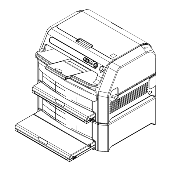
Page 137: Overall Configuration And Names Of Parts
MD-2 Overall Configuration and Names of Parts 1.3.1 External View Head cover Extension tray Upper rear cover Upper tray cover Right cover Lower tray cover Main power switch (ON ( I ):Main power source ON OFF (O):Main power source OFF) Front cover Lower front cover* Power connector... -
Page 138: Operation Panel
MD-3 1.3.2 Operation Panel n Example Display n Layout Display Meaning Indicates that the equipment is currently starting up. (From power ON to initialization) Indicates that the equipment is currently initializing Error code (203 in this example) Indicates sleep state Indicates currently service utility mode. - Page 139 MD-4 1.3.3 Layout of External Interface Connectors CAUTION When touching the blind plate of the USB connector, be sure to use a wristband to ground yourself. Otherwise the equipment may not operate properly. <NOTE> It is impossible to use two USB memories simultaneously. Only the one recognized first will be enabled.
-
Page 140: Layout Of Units
MD-5 1.3.4 Layout of Units Head (H) Cover (P) Frame (K1) Sub-scanning section (E) Controller Upper conveyor section (D1) Upper magazine set section (A1) Upper removal section (B1) Lower conveyor section (D2) (Optional) Lower magazine Lower removal section (B2) set section (A2) (Optional) (Optional) Lower frame (K2) -
Page 141: Layout Of I/O Parts And Description Of Functions
MD-6 1.3.5 Layout of I/O Parts and Description of Functions Section Symbol Name Type Remarks n Magazine Set Section/Removal Section Upper maga- SA11 Film size detection sensor Penetration • Upper magazine detec- zine set section 1 (Upper) type sensor tion (A1) (PI: 5mm) •... - Page 142 MD-7 n Conveyor Section/Sub-Scanning Section Section Symbol Name Type Remarks SD13 Conveyor sec- MD11 Conveyance motor 2-phase Conveys film from re- tion (D1) pulse motor moval section to convey- SD12 or exit SD11 MD12 Reference plate drive mo- 2-phase Moves film positioning tor (Upper) pulse motor guide assembly refer-...
- Page 143 MD-8 n Head/Film Edge Sensor Section Symbol Name Type Remarks THH6 Head (H) Head up/down drive mo- 2-phase Perform thermal head pulse motor pressurization/depres- surization Thermal head HH1, Head heater Adjust thermal head tem- perature TPH1 Thermal protector Cuts off head power, head heater (HH1, HH2) power when the thermal head is abnormally hot...
- Page 144 MD-9 n Frame/Covers Section Symbol Name Type Remarks FANP1 SK12 Upper frame SK12 Head cover interlock Microswitch When the head cover is (K1) switch open, +24V power sup- plied to load parts is cut FANK1 FANK1 Controller fan DC fan Cover (P) FANP1 Head cooling fan 1...
- Page 145 MD-10 n Sheet-Feeder Unit (Option) Section Symbol Name Type Remarks SK21 Lower maga- SA21 Film size detection sensor Penetration • Lower magazine detec- SB22 zine set section 1 (Lower) type sensor tion (A2) (PI: 5mm) • Detects magazine SD21 number when com- SA22 Film size detection sensor Penetration...
-
Page 146: Board Layout
MD-11 1.3.6 Board Layout Name Main function PIS28A LED28A Density measurement section light-emitting board PDD28A PNL28A PDD28A Density measurement section light-sensing board LED28A SND32A/B CPU32A (CPU board) Overall control of equipment, network input, image pro- cessing PIS28A Power supply unit DC power supply to equipment SND32A/B (Sensor driver Mechanical drive parts drive, I/O parts control, signal... -
Page 147: Starting Up And Ending The Equipment
MD-12 STARTING UP AND ENDING THE Handling of Equipment Errors EQUIPMENT 2.2.1 Level 1 Error The following errors can be recovered by user intervention. These errors are Powering ON automatically logged. When the error occurs during film conveyance, the error is displayed after the mechanism is initialized so that the film can be removed. -
Page 148: Level 0 Error
MD-13 2.2.2 Level 0 Error n Film Jam Imaginable fatal errors are check failure at initialization, head movement failure, and When no change is detected at the sensor within a predetermined time during the edge detection failure at the film edge detection sensor. film conveyance process, an error message is displayed, assuming that a jam has occurred. -
Page 149: Powering Off
MD-14 Powering OFF PFIF log Records message transmission/reception between the formatter and printer. When the main power switch of the equipment is at ON position, the equipment shuts Jam log down under the following conditions: Collects logs related to jams when jams occur. Means Conditions Remarks... -
Page 150: Description Of Electrical Control
MD-15 DESCRIPTION OF ELECTRICAL CONTROL System Block Diagram AC input (100-120V/200-240V) Power supply unit Thermal head +14.8V Relay board SND board Operation panel Thermal protector (V850) Head heater Head thermistor PS_ON PS_ON Control circuit Density measurement PDD CPU board Density measurement LED Edge sensor (D425) Sensor... - Page 151 MD-16 Interlock Control Functions of Boards The drive power supply cutoff by the interlock switch of this equipment is shown 3.3.1 CPU Board below. n Detection of Disconnection by Photocoupler n Outline The ON/OFF state of interlock switches, relays, and fuses is converted to the ON/OFF The CPU board performs overall control of the equipment, network input, and image signal by the photocoupler, and used for software control.
- Page 152 MD-17 3.3.2 SND Board n Main Functions n Outline l Sensor I/F The SND board performs I/O control of the equipment by controlling the CPU board. Sensor input Head resistance • PI 5mm GAP type ..............×11 SND board measurement Density measure- •...
-
Page 153: Rly Board
MD-18 3.3.3 RLY Board l Operation Panel I/F • LED ON/OFF control ..............×11 n Outline • Switch ..................×3 • Buzzer ..................×1 The RLY board performs switching between the head power supply and the resistance measurement. l Others +14.8V For Analysis Head RLY32A •... - Page 154 MD-19 3.3.4 Power Supply Unit n Outline of Power Supply Specifications Input AC voltage 100 to 240VAC Output DC voltage • +14.8V • +24.0V • +12.0V • +5.0V • +3.3V • +5VAUX Input frequency 50 to 60 Hz Current leakage 0.5mA or less MD-19 DRYPIX Lite Service Manual...
- Page 155 MD-20 IMAGE PROCESSING {MD (DRYPIX 2000) :5._IMAGE PROCESSING} MD-20 DRYPIX Lite Service Manual 016-201-06E 01.27.2012 FM5920...
- Page 156 MD-21 PRINTING FORMATS {MD (DRYPIX 2000) :6._PRINTING FORMATS} MD-21 DRYPIX Lite Service Manual 016-201-06E 01.27.2012 FM5920...
- Page 157 MD-22 BLANK PAGE MD-22 DRYPIX Lite Service Manual 016-201-06E 01.27.2012 FM5920...
- Page 158 MD-23 BLANK PAGE MD-23 DRYPIX Lite Service Manual 016-201-06E 01.27.2012 FM5920...
- Page 159 Revised (FM4903) All pages 08.31.2006 Revised (FM4958) 1, 3, 5-8, 10-13, 15, 29, 30, 32, 33, 35-55 DRYPIX 2000 SERVICE MANUAL 10.18.2006 Revised (FM5036) 02.15.2007 Revised (Revision for main unit software 3, 10-21, 26-59 version V2.0 and V2.1, etc.) (FM5075) 01.27.2012...
-
Page 160: Troubleshooting Method
When analyzing malfunctions from abnormal operations, such as an errored-out initialization, refer to “3.ABNORMAL OPERATIONS”. {MT:3_ABNORMAL OPERATIONS} When checking the equipment in troubleshooting, refer also to “SERVICE PARTS LIST, 14. CIRCUIT DIAGRAM”. {SP:14_CIRCUIT DIAGRAM} MT-1 DRYPIX 2000 Service Manual 016-201-02E 08.31.2006 FM4958... -
Page 161: Error Code
: Index display : Place of error (P: Printer, F:Formatter) AAAA : Error code (4-digit hexadecimal) BBBB : Detailed error code (4-digit hexadecimal) CCCCCC : Date error occurred DDDD : Time error occurred MT-2 DRYPIX 2000 Service Manual 016-201-01E 03.24.2006 FM4903... - Page 162 Test pattern generation error Main MAIN control error File transfer error PCUTL (Using the PC Tool in normal state) File transfer error Installer (Using the PC Tool at initialization) StartUp Initialization error MT-3 DRYPIX 2000 Service Manual 016-201-04E 02.15.2007 FM5075...
-
Page 163: Format Of Detailed Information
Find the format information from the 4-digit detailed information, and Displays states of sensors (0/1) when an error occurs. analyze the problem. l 2-A-2 (Conveyance Related Information (Type S1)) Displays states of sensors (0/1) when an error occurs. MT-4 DRYPIX 2000 Service Manual 016-201-01E 03.24.2006 FM4903... - Page 164 4 : Conversion error 5 : Line specification error 6 : Column specification error 7 : Size specification error 8 : External file data error A : Data range error (Detected by application) MT-5 DRYPIX 2000 Service Manual 016-201-02E 08.31.2006 FM4958...
- Page 165 04 : Removal mechanism individual operation/Removal mechanism continuous operations Parameter number 0: Home Positioning 1: Film surface detection position 2: Suction position 3: Upper deadpoint detection position 4: Film fanning 5: Film release 6: Conveyance MT-6 DRYPIX 2000 Service Manual 016-201-02E 08.31.2006 FM4958...
-
Page 166: 2.2.2 Mfc Related (Data Setting/System Related) Error Detailed Information
2: Lead error 3: Write error 4: Conversion error 5: Line specification error 6: Column specification error 7: Size specification error 8: External file data error A: Data range error (Detected by application) MT-7 DRYPIX 2000 Service Manual 016-201-02E 08.31.2006 FM4958... -
Page 167: Hed Related (Head Control Related) Error Detailed Information
When disconnection of the thermistor is detected, the detected thermistor number will be displayed. l If one thermistor is disconnected l If two thermistors are disconnected Number 1 to 6: Head thermistor number/ambient thermistor number MT-8 DRYPIX 2000 Service Manual 016-201-02E 08.31.2006 FM4958... -
Page 168: Error Code Table
Formal Name Name SND board SND25A board CPU board CPU25A board THC board THC25A board PNL board PNL25A board LED board LED15A board PDD board PDD15A board Printer/print mechanism Formatter Compact flush memory MT-9 DRYPIX 2000 Service Manual 016-201-01E 03.24.2006 FM4903... -
Page 169: Printer
1. Using the M-Utility, check sensors, motors, and perform mechanism 2-A-4 return detection error CLOSE. adjustments. (Retryover) 2. If the problem still persists, replace sensors/motors. 3. If the problem still persists, replace the SND board. MT-10 DRYPIX 2000 Service Manual 016-201-04E 02.15.2007 FM5075... - Page 170 1. Using the M-Utility, check sensors, motors, and perform mechanism 2-A-2 film surface detection error SB12 does not become CLOSE. adjustments. (Retryover) 2. If the problem still persists, replace sensors/motors. 3. If the problem still persists, replace the SND board. MT-11 DRYPIX 2000 Service Manual 016-201-04E 02.15.2007 FM5075...
- Page 171 HP rise detection after film suction, but SB23 does not 2-A-3 1. Using the M-Utility, check sensors, motors, and perform mechanism error become CLOSE. adjustments. (Retryover) 2. If the problem still persists, replace sensors/motors. MT-12 DRYPIX 2000 Service Manual 016-201-04E 02.15.2007 FM5075...
- Page 172 1. Using M-Utility, perform sensor check, motor check, mechanism adjustment. at grip release SB11 did not become OPEN. 2. If problems are detected, replace the sensor/motor. 3. If the problem still persists, replace the SND board. MT-13 DRYPIX 2000 Service Manual 016-201-04E 02.15.2007 FM5075...
- Page 173 Attempted to check the FUSE5 state, but 0263 FUSE5 operation 1. Perform sensor check using the M-Utility. 2-A-1 could not confirm. 2. If detection, replace parts. 3. If the problem still persists, replace the SND board. MT-14 DRYPIX 2000 Service Manual 016-201-04E 02.15.2007 FM5075...
- Page 174 1. Using M-Utility, perform sensor check, motor check, mechanism adjustment. error become CLOSE. 2. If problems are detected, replace the sensor/motor. (Retryover) 3. If the problem still persists, replace the SND board. MT-15 DRYPIX 2000 Service Manual 016-201-04E 02.15.2007 FM5075...
- Page 175 Image processing 3 does not end. Image processing 3 CPU board error 0558 Image processing 3 error None timeout error 1. Replace the CPU board. 2. Reinstall the software and check again.. MT-16 DRYPIX 2000 Service Manual 016-201-04E 02.15.2007 FM5075...
- Page 176 1. Set the card properly in the CPU board. None file read error (CF memory card access error) 2. Replace the card with a new one. 3. Replace the CPU board. 4. Reinstall the software and check again. MT-17 DRYPIX 2000 Service Manual 016-201-04E 02.15.2007 FM5075...
- Page 177 1. Set the card properly in the CPU board. None (CF memory card access (CF memory card access error) 2. Replace the card with a new one. error) 3. Replace the CPU board. 4. Reinstall the software and check again. MT-18 DRYPIX 2000 Service Manual 016-201-04E 02.15.2007 FM5075...
- Page 178 1. Set the card properly in the CPU board. None open error (CF memory card access error) 2. Replace the card with a new one. 3. Replace the CPU board. 4. Reinstall the software and check again. MT-19 DRYPIX 2000 Service Manual 016-201-04E 02.15.2007 FM5075...
- Page 179 1. Set the card properly in the CPU board. None parameter file read error (CF memory card access error) 2. Replace the card with a new one. 3. Replace the CPU board. 4. Reinstall the software and check again. MT-20 DRYPIX 2000 Service Manual 016-201-04E 02.15.2007 FM5075...
- Page 180 1. Set the card properly in the CPU board. None open error (CF memory card access error) 2. Replace the card with a new one. 3. Replace the CPU board. 4. Reinstall the software and check again. MT-21 DRYPIX 2000 Service Manual 016-201-04E 02.15.2007 FM5075...
- Page 181 1. Set the card properly in the CPU board. None error (CF memory card access error) 2. Replace the card with a new one. 3. Replace the CPU board. 4. Reinstall the software and check again. MT-22 DRYPIX 2000 Service Manual 016-201-01E 03.24.2006 FM4903...
- Page 182 1. Set the card properly in the CPU board. None error (CF memory card access error) 2. Replace the card with a new one. 3. Replace the CPU board. 4. Reinstall the software and check again. MT-23 DRYPIX 2000 Service Manual 016-201-01E 03.24.2006 FM4903...
- Page 183 None 2. Replace the card with a new one. error (CF memory card access error) 3. Replace the CPU board. 4. Reinstall the software and check again. MT-24 DRYPIX 2000 Service Manual 016-201-01E 03.24.2006 FM4903...
- Page 184 1. Set the card properly in the CPU board. None parameter file read error (CF memory card access error) 2. Replace the card with a new one. 3. Replace the CPU board. 4. Reinstall the software and check again. MT-25 DRYPIX 2000 Service Manual 016-201-01E 03.24.2006 FM4903...
- Page 185 The edge sensor is not operating properly, or CPU board malfunction. 1. Replace the edge sensor. 05E0 Edge sensor error Left edge sensor error 2. Replace the SND board. None 3. Replace the CPU board. 4. Reinstall the software and check again. MT-26 DRYPIX 2000 Service Manual 016-201-04E 02.15.2007 FM5075...
- Page 186 1. Check that the SND board, various input boards, and related connectors are set normally. 2. Replace the cooling fan and thermistor. 1212 Cover open Cover is opened. Close the cover. 2-A-1 MT-27 DRYPIX 2000 Service Manual 016-201-04E 02.15.2007 FM5075...
- Page 187 SD12 did not become OPEN (film trailing magazine. 2-A-4 error edge detection). 1. Check the film size. 2. Check the sensors/motors. SD12, MD11, ME1 3. Check the cleaning rollers. 4. Check the head. MT-28 DRYPIX 2000 Service Manual 016-201-04E 02.15.2007 FM5075...
- Page 188 1269 1. Check the sensors/motors. 2-A-4 conveyor jam error and SD21 did not become OPEN (film SD11, SD21, MD11, ME1 trailing edge detection). 2. Check the cleaning rollers. 3. Check the head. MT-29 DRYPIX 2000 Service Manual 016-201-04E 02.15.2007 FM5075...
- Page 189 Although film was conveyed to the Conveyor section jam Open the rear cover and remove the film. 1289 recording unit, failed to detect SD21 2-A-4 error 1. Check the sensors/motors. OPEN (film trailing edge detection). SD21, MD11 MT-30 DRYPIX 2000 Service Manual 016-201-04E 02.15.2007 FM5075...
- Page 190 Remedy: Replace head or replace resistance unit. No recording temperature Cause: Executed save without recording temperature data. 1542 No recording temperature save table None save table Solution: Turn ON the temperature recording mode. MT-31 DRYPIX 2000 Service Manual 016-201-04E 02.15.2007 FM5075...
- Page 191 1. Using the M-Utility, check sensors, motors, and perform mechanism 2-A-1 deviation detection error become OPEN. adjustments. 2. If the problem still persists, replace sensors/motors. 3. If the problem still persists, replace the SND board. MT-32 DRYPIX 2000 Service Manual 016-201-04E 02.15.2007 FM5075...
- Page 192 SB12 does not become CLOSE. 2. If the problem still persists, replace sensors/motors. 3. If the problem still persists, replace the SND board. MT-33 DRYPIX 2000 Service Manual 016-201-04E 02.15.2007 FM5075...
- Page 193 1. Using the M-Utility, check sensors, motors, and perform mechanism 2-A-3 error detection position into the bellows, but adjustments. SB22 does not OPEN. 2. If the problem still persists, replace sensors/motors. 3. If the problem still persists, replace the SND board. MT-34 DRYPIX 2000 Service Manual 016-201-04E 02.15.2007 FM5075...
- Page 194 TPH confirmation standby Occurs due to the electrical circuit, and is not a defect. In this case, open and 2277 Failed to confirm TPH1, FUSE6 status. 2-A-1 timeout close the cover to re-initialize. MT-35 DRYPIX 2000 Service Manual 016-201-04E 02.15.2007 FM5075...
- Page 195 Solution: Replace the density measurement board. Density measurement Density measurement valid data count Cause: Density measurement did not carried out property. 25E4 valid data count error error Solution: Replace the density measurement board. MT-36 DRYPIX 2000 Service Manual 016-201-04E 02.15.2007 FM5075...
- Page 196 CAN communication mechanism SND board malfunction. Head cooling standby 2902 Head cooling standby warning 1. Check that the SND board, various input boards, and related connectors are warning set normally. 2. Replace the cooling fan and thermistor. MT-37 DRYPIX 2000 Service Manual 016-201-04E 02.15.2007 FM5075...
- Page 197 Heater device driver 1. Check that the SND board, input boards, and related connectors are set 2907 Heater could not be started. None warning error properly. 2. Replace the 24 head voltage switching relay. MT-38 DRYPIX 2000 Service Manual 016-201-04E 02.15.2007 FM5075...
-
Page 198: Formatter
Invalid UserImageNum.txt Save equipment individual data (requires UserImageNum.txt). 2:Non existing keyword 3:Non existing value Check SDRAM capacity, save equipment individual data, reboot 0001 FFFF Insufficient virtual memory None system, and observe conditions. MT-39 DRYPIX 2000 Service Manual 016-201-04E 02.15.2007 FM5075... - Page 199 Save equipment individual data (requires log analysis). code, file name Save equipment individual data (requires log analysis), reboot system, Place of occurrence in source 0002 0013 Requested print ID is illegal. and observe conditions. code MT-40 DRYPIX 2000 Service Manual 016-201-04E 02.15.2007 FM5075...
- Page 200 0014 Failed in moving file. and observe conditions. code Save equipment individual data (requires log analysis), reboot system, Place of occurrence in source 0002 0015 Unexpected case occurred. and observe conditions. code MT-41 DRYPIX 2000 Service Manual 016-201-04E 02.15.2007 FM5075...
- Page 201 Re-executed format calculation without annotation Save equipment individual data (requires imginf.prm analysis), acquire Place of occurrence in source 0003 0008 information error job information (requires xxx.job/xxx.flm). code MT-42 DRYPIX 2000 Service Manual 016-201-04E 02.15.2007 FM5075...
- Page 202 Save equipment individual data (requires log analysis), reboot system, 0004 1F85 Unable to continue operations due to internal error. None and observe conditions. 0004 1F90 File does not exist. Check if file is present None MT-43 DRYPIX 2000 Service Manual 016-201-04E 02.15.2007 FM5075...
- Page 203 CF. Reboot the system or reinstall and observe the conditions. If no 2706 xxxx PNL unit LCD abnormal error xxxx is arbitrary value improvements are seen, replace the CF. MT-44 DRYPIX 2000 Service Manual 016-201-04E 02.15.2007 FM5075...
- Page 204 Error in system date at start (when there is conflict in 2610 xxxx Reboot the system and observe conditions. Incorrect time-keeping is not time itself) detected. MT-45 DRYPIX 2000 Service Manual 016-201-04E 02.15.2007 FM5075...
- Page 205 Failed in opening and creating files. and observe conditions. code, file name Save equipment individual data (requires log analysis), reboot system, Place of occurrence in source 0007 000B Invalid status and observe conditions. code, status MT-46 DRYPIX 2000 Service Manual 016-201-04E 02.15.2007 FM5075...
- Page 206 Failed in calling JOB generation request (cleaning) Check SDRAM capacity, save equipment individual data, reboot Place of occurrence in source 0008 000F method. system, and observe conditions. code MT-47 DRYPIX 2000 Service Manual 016-201-04E 02.15.2007 FM5075...
- Page 207 Failed in calling output processing completion Check SDRAM capacity, save equipment individual data, reboot Place of occurrence in source 0008 001F notification method. system, and observe conditions. code MT-48 DRYPIX 2000 Service Manual 016-201-04E 02.15.2007 FM5075...
- Page 208 Check SDRAM capacity, save equipment individual data, reboot Place of occurrence in source 0008 002E Failed in calling uniformity table re-reading method system, and observe conditions. code MT-49 DRYPIX 2000 Service Manual 016-201-04E 02.15.2007 FM5075...
- Page 209 Place of occurrence in source 0008 0043 Analysis log information: USB related error Check MAIN error log. code Place of occurrence in source 0008 0044 Reprint image: USB related error Check MAIN error log. code MT-50 DRYPIX 2000 Service Manual 016-201-04E 02.15.2007 FM5075...
- Page 210 Failed in renewing number of the accumulated used Check SDRAM capacity, save equipment individual data, reboot Place of occurrence in source 0008 0054 films. system, and observe conditions. code MT-51 DRYPIX 2000 Service Manual 016-201-04E 02.15.2007 FM5075...
- Page 211 Failed in deleting pas log. system, and observe conditions. code Check SDRAM capacity, save equipment individual data, reboot Place of occurrence in source 0008 0060 Failed in identifying log acquisition mode. system, and observe conditions. code MT-52 DRYPIX 2000 Service Manual 016-201-04E 02.15.2007 FM5075...
- Page 212 FTP directory of the PC for servicing, and observe conditions. 000A 0003 Searched for corresponding file but did not exist Reinstall or add the corresponding file again. Name of file which failed search MT-53 DRYPIX 2000 Service Manual 016-201-04E 02.15.2007 FM5075...
- Page 213 Installer (StartUp) Error Detailed Significance Remedy Detailed information code code 000B 0003 Searched for corresponding file but did not exist Reinstall or add the corresponding file again. Name of file which failed search MT-54 DRYPIX 2000 Service Manual 016-201-04E 02.15.2007 FM5075...
- Page 214 1. Check the memory capacity. 000C 000D File copy error to RAMDISK None 2. Replace the memory. 1. Check the memory capacity. 000C 000E Image processing memory initialization error None 2. Replace the memory. MT-55 DRYPIX 2000 Service Manual 016-201-04E 02.15.2007 FM5075...
- Page 215 2. Check that CF memory card is set correctly. None 3. Replace CF memory card. 1. Install the software. 000C 0018 Message error 2. Check that CF memory card is set correctly. None 3. Replace CF memory card. MT-56 DRYPIX 2000 Service Manual 016-201-04E 02.15.2007 FM5075...
- Page 216 As several board errors may 1. Check that the SND board connector is set properly. 000C 1004 SND connection board disconnected occur at the same time, determine 2. Replace the SND board. according to Bit. MT-57 DRYPIX 2000 Service Manual 016-201-04E 02.15.2007 FM5075...
-
Page 217: Abnormal Operations
Creation of a specified folder in the virtual disk. IL-4 Preparation of an image editing area. IL-5 None. IL-6 Creation of a timer task. IL-7 Creation of Main Control Task and PRT Control Task. MT-58 DRYPIX 2000 Service Manual 016-201-04E 02.15.2007 FM5075... - Page 218 MT-59 BLANK PAGE MT-59 DRYPIX 2000 Service Manual 016-201-04E 02.15.2007 FM5075...
- Page 219 CONTROL SHEET Issue Date Revision Number Reason Pages Affected 01.27.2012 Revised (FM5920) All pages DRYPIX 2000 SERVICE MANUAL TROUBLESHOOTING (MT) (DRYPIX Lite) DRYPIX Lite Service Manual 016-201-06E 01.27.2012 FM5920...
- Page 220 MT-1 TROUBLESHOOTING METHOD When malfunctions occur in the equipment, analyze them from error codes, abnormal image, and abnormal operation and perform the required corrections. MT-1 DRYPIX Lite Service Manual 016-201-06E 01.27.2012 FM5920...
- Page 221 MT-2 ERROR CODE Format of Detailed Information Perform this check only for analyzing error codes of the printer. In the usual troubleshooting, find the corresponding error code from the error code Checking Error Codes tables, and refer to the suspected causes and remedy methods indicated to resolve the problem.
-
Page 222: Flh Related (Conveyance) Errors Detailed Information
MT-3 2.2.1 FLH Related (Conveyance) Errors Detailed Information l 2-A-3 (Conveyance Related Information (Type S2)) Displays states of sensors (0/1) when an error occurs. n 2-A (Sensor Related Errors) [Bit map] Errors occurring in initialization self-diagnosis, removal, recording, constant monitoring, etc. (Including mechanism, etc.) Convert the hexadecimal 4-digit code to binary, compare the bit maps, and investigate SD12 SD23 SD21... - Page 223 MT-4 n 2-B (File I/O Error) n 2-E (Operation Error) l 2-B-1 (Type F) l 2-E-1 (Type U) Error which occurs when a file could not be accessed properly. Displays the number Displays the PC-Utility command number which occur when the removal operation of the file causing the error and the causes.
- Page 224 MT-5 2.2.2 MFC Related (Data Setting/System Related) Error 2.2.3 HED Related (Head Control Related) Error Detailed Detailed Information Information n 3-B (File I/O Error) n 5-1 (Density Measurement Error) Error which occurs when file could not be accessed correctly. Displays the cause of If the measured value is insufficient during density measurement, the measured data the access error.
- Page 225 MT-6 Error Code Table n 9-2 (Thermistor Temperature Adjustment Error) When temperature adjustment error of the thermistor (temperature adjustment Names abbreviated in error code tables are as follows. timeout, AD conversion timeout, temperature exceeded) is detected, the detected thermistor number will be displayed. Abbreviated Formal Name Name...
- Page 226 MT-7 2.3.1 Printer Error Detailed Error Name Significance Probable Cause and Remedy Display code information Format 1212 Cover open A cover is open. Close the cover. 2-A-5 No magazine loaded 1210 No magazine is loaded. Load the magazine. 2-A-2 (Main unit) No magazine loaded 1211 No magazine is loaded.
- Page 227 MT-8 Error Detailed Error Name Significance Probable Cause and Remedy Display code information Format A jam occurred during sub-scanning conveyance (image recording). When a jam occurs, open the rear open/close cover and head cover, then remove the film. [Example] Conveyed film to the recording section, but This problem can occur when 26 x 36 cm size film is set in the 26 1256 Recording section jam error...
- Page 228 MT-9 Error Detailed Error Name Significance Probable Cause and Remedy Display code information Format Jam occurred during transmission at the recording section. When a jam occurs, open the rear open/close cover and head During remaining film ejection, conveyed film cover, then remove the film. Remaining film ejection to the recording section, but SD11 and SD21 1269...
- Page 229 MT-10 Error Detailed Error Name Significance Probable Cause and Remedy Display code information Format A jam occurred during sub-scanning conveyance (image recording). Conveyed film to the recording section and When a jam occurs, open the rear open/close cover and head detected SD12 OPEN (film trailing edge cover, then remove the film.
- Page 230 MT-11 Error Detailed Error Name Significance Probable Cause and Remedy Display code information Format A magazine set to "disable" is loaded in the main body. Referred to the information on the main body Main body magazine setting 1. Load a magazine available. magazine and found that the magazine was error 2.
- Page 231 MT-12 Error Detailed Error Name Significance Probable Cause and Remedy Display code information Format FPMC error Stop response is not issued from the driver 0204 An error occurred at the PCI communication system. 2-D-1 (No response at cancellation) when the motor is stopped. Malfunction of SH1 sensor or MH1 motor.
- Page 232 MT-13 Error Detailed Error Name Significance Probable Cause and Remedy Display code information Format Malfunction of SB21 sensor or MB21 motor. Or mechanical system error, malfunction of the PCI communication system or the SB21 port or MB21 controller on Initialization sheet-feeder unit At initialization, attempted to return suction the SND board.
- Page 233 MT-14 Error Detailed Error Name Significance Probable Cause and Remedy Display code information Format Malfunction of SB13 sensor or MB11 motor. Or mechanical system error, malfunction of the SB13 port or At film removal, attempted to move the MB11 controller on the SND board. Main body removal section HP suction cup arm to the upper deadpoint after 1.
- Page 234 MT-15 Error Detailed Error Name Significance Probable Cause and Remedy Display code information Format Malfunction of SD13 sensor or MD12 motor. Or mechanical system error, malfunction of the PCI communication system or the SD13 port or MD12 controller on Main body film positioning During film positioning reference plate the SND board.
- Page 235 MT-16 Error Detailed Error Name Significance Probable Cause and Remedy Display code information Format FUSE3 wire break or malfunction of PCI communication system or the FUSE3 port on the SND board. Attempted but could not confirm the status of 0261 FUSE3 operation 1.
- Page 236 MT-17 Error Detailed Error Name Significance Probable Cause and Remedy Display code information Format Malfunction of SB13 sensor or MB11 motor. At film removal, attempted to move the Or mechanical system error or malfunction of the PCI suction cup arm to the upper deadpoint after communication system or the SB13 port or MB11 controller on Main body removal section film suction, but SB13 does not become...
- Page 237 MT-18 Error Detailed Error Name Significance Probable Cause and Remedy Display code information Format The CF memory card is not set in the CPU board properly, the card or the CPU board is faulty. Or data is inappropriate, or data is insufficient. Head correction parameter file Head correction parameter file open error 05A2...
- Page 238 MT-19 Error Detailed Error Name Significance Probable Cause and Remedy Display code information Format The CF memory card is not set in the CPU board properly, the card or the CPU board is faulty. Density measurement value Density measurement value conversion Or data is inappropriate, or data is insufficient.
- Page 239 MT-20 Error Detailed Error Name Significance Probable Cause and Remedy Display code information Format The CF memory card is not set in the CPU board properly, the card or the CPU board is faulty. Or data is inappropriate, or data is insufficient. Temperature rise correction Temperature rise correction parameter file 05B2...
- Page 240 MT-21 Error Detailed Error Name Significance Probable Cause and Remedy Display code information Format The CF memory card is not set in the CPU board properly, the card or the CPU board is faulty. Or data is inappropriate, or data is insufficient. Load fluctuation correction Load fluctuation correction table file open 05B7...
- Page 241 MT-22 Error Detailed Error Name Significance Probable Cause and Remedy Display code information Format The CF memory card is not set in the CPU board properly, the card or the CPU board is faulty. Or data is inappropriate, or data is insufficient. Temperature measurement Temperature measurement table file close 05BC...
- Page 242 MT-23 Error Detailed Error Name Significance Probable Cause and Remedy Display code information Format The CF memory card is not set in the CPU board properly, the card or the CPU board is faulty. Or data is inappropriate, or data is insufficient. Load fluctuation correction Load fluctuation correction weighting table file 05CD...
- Page 243 MT-24 Error Detailed Error Name Significance Probable Cause and Remedy Display code information Format The CF memory card is not set in the CPU board properly, the card or the CPU board is faulty. Resistance inconsistency correction data Resistance inconsistency 1.
- Page 244 MT-25 Error Detailed Error Name Significance Probable Cause and Remedy Display code information Format The CF memory card is not set in the CPU board properly, the card or the CPU board is faulty. Or data is inappropriate, or data is insufficient. Image processing 3 parameter Image processing 3 parameter file read error 05DC...
- Page 245 MT-26 Error Detailed Error Name Significance Probable Cause and Remedy Display code information Format The CF memory card is not set in the CPU board properly, the card or the CPU board is faulty. Or data is inappropriate, or data is insufficient. Clear film compensation Clear film compensation parameter file read 05E2...
- Page 246 MT-27 Error Detailed Error Name Significance Probable Cause and Remedy Display code information Format Malfunction related to thermistors, cooling fans, or heaters on the PCI communication system or on the SND board or malfunction of the PCI communication system or the SND board. 0904 AD conversion timeout error AD conversion timeout error...
- Page 247 MT-28 Error Detailed Error Name Significance Probable Cause and Remedy Display code information Format Malfunction of the PCI communication system, the SND board, or Density measurement the density measurement section. 25E0 Density measurement sequence error sequence error 1. Replace the PCI communication system or the SND board. 2.
- Page 248 MT-29 Error Detailed Error Name Significance Probable Cause and Remedy Display code information Format The CF memory card is not set in the CPU board properly, the card or the CPU board is faulty. Or data is inappropriate, or data is insufficient. Temperature data file read 1C02 Temperature data file read error...
- Page 249 MT-30 Error Detailed Error Name Significance Probable Cause and Remedy Display code information Format Malfunction of SB11 sensor or MB11 motor. Or mechanical system error, malfunction of the PCI communication system or the SB11 port or MB11 controller on At initialization, attempted to deviate suction Initialization removal section the SND board.
- Page 250 MT-31 Error Detailed Error Name Significance Probable Cause and Remedy Display code information Format Malfunction of SB22 sensor or MB21 motor. Or mechanical system error, malfunction of the PCI At film removal, attempted to move the communication system or the SB22 port or MB21 controller on suction cup arm from the upper deadpoint to the SND board.
- Page 251 MT-32 Error Detailed Error Name Significance Probable Cause and Remedy Display code information Format Malfunction of SB11 sensor or MB11 motor. Or mechanical system error, malfunction of the PCI communication system or the SB11 port or MB11 controller on At film removal, attempted to move the Removal section HP rise the SND board.
- Page 252 MT-33 Error Detailed Error Name Significance Probable Cause and Remedy Display code information Format Film dropped During film removal. Or, malfunction of the SB11, SB12, SB13, SD11 sensors or MB11 motor. Malfunction of the mechanical system or the PCI communication system, or malfunction of the SB11, SB12, SB13, SD11 ports or Conveyor section conveyance After completing removal processing, SD11...
- Page 253 MT-34 2.3.2 Formatter n DICOM Error Detailed Significance Probable Cause and Remedy Detailed Information Format Display code code Check the SDRAM capacity, save the equipment individual data, 0001 0001 Failed in starting the DICOM main thread. None reboot the system, and observe whether the problem persists. 0001 0002 Invalid Dicom.dat contents...
- Page 254 MT-35 n Spooler Error Detailed Significance Probable Cause and Remedy Detailed Information Format Display code code Check the SDRAM capacity, save the equipment individual data, Place of occurrence in source 0002 0001 Failed in creating a thread. (Internal error) reboot the system, and observe whether the problem persists. code Check the SDRAM capacity, save the equipment individual data, Place of occurrence in source...
- Page 255 MT-36 n ImgPrc Error Detailed Significance Probable Cause and Remedy Detailed Information Format Display code code Check the SDRAM capacity, save the equipment individual data, Place of occurrence in source 0003 0001 An error occurred due to system call. reboot the system, and observe whether the problem persists. code Check the SDRAM capacity, save the equipment individual data, Place of occurrence in source...
- Page 256 MT-37 n Output Error Detailed Significance Probable Cause and Remedy Detailed Information Format Display code code Check the SDRAM capacity, save the equipment individual data, 0004 1EB1 Failed in starting output main thread. None reboot the system, and observe whether the problem persists. Check the SDRAM capacity, save the equipment individual data, 0004 1F7C...
- Page 257 MT-38 n Panel Error Detailed Significance Probable Cause and Remedy Detailed Information Format Display code code Reboot the system or reinstall, and observe whether the problem 0701 xxxx PDM task panel driver initialization error xxxx is arbitrary value persists. If no improvements are seen, replace the CF. Reboot the system or reinstall, and observe whether the problem 2701 xxxx...
- Page 258 MT-39 n Utility Error Detailed Significance Probable Cause and Remedy Detailed Information Format Display code code Message file format NG error 2600 xxxx Reinstall the software. xxxx is arbitrary value (Mainly due to file corruption) Message file number of items NG error 2601 xxxx Reinstall the software.
- Page 259 MT-40 n JobMake Error Detailed Significance Probable Cause and Remedy Detailed Information Format Display code code Check the SDRAM capacity, save the equipment individual data, Place of occurrence in source 0007 0001 Failed in creating a thread. (Internal error) reboot the system, and observe whether the problem persists. code Check the SDRAM capacity, save the equipment individual data, Place of occurrence in source...
- Page 260 MT-41 n Main Error Detailed Significance Probable Cause and Remedy Detailed Information Format Display code code Failed in securing the area for communication Check the SDRAM capacity, save the equipment individual data, Place of occurrence in source 0008 0001 processing. reboot the system, and observe whether the problem persists.
- Page 261 MT-42 Error Detailed Significance Probable Cause and Remedy Detailed Information Format Display code code Failed in calling the method of instructing energy Check the SDRAM capacity, save the equipment individual data, Place of occurrence in source 0008 0013 saving. reboot the system, and observe whether the problem persists. code Check the SDRAM capacity, save the equipment individual data, Place of occurrence in source...
- Page 262 MT-43 Error Detailed Significance Probable Cause and Remedy Detailed Information Format Display code code Failed in calling the method of initializing the Check the SDRAM capacity, save the equipment individual data, Place of occurrence in source 0008 0026 output control. reboot the system, and observe whether the problem persists.
- Page 263 MT-44 Error Detailed Significance Probable Cause and Remedy Detailed Information Format Display code code Check the content of the USB storage. Place of occurrence in source 0008 003F USB installation: No files to be loaded via USB. Cannot recognize it as the installer. code Place of occurrence in source 0008...
- Page 264 MT-45 Error Detailed Significance Probable Cause and Remedy Detailed Information Format Display code code Failed in calling the method of notifying the status Check the SDRAM capacity, save the equipment individual data, Place of occurrence in source 0008 0051 lamp control. reboot the system, and observe whether the problem persists.
- Page 265 MT-46 Error Detailed Significance Probable Cause and Remedy Detailed Information Format Display code code Check the SDRAM capacity, save the equipment individual data, Place of occurrence in source 0008 0064 Failed in updating the NETINF file. reboot the system, and observe whether the problem persists. code MT-46 DRYPIX Lite Service Manual...
- Page 266 MT-47 n PCUTL Error Detailed Significance Probable Cause and Remedy Detailed Information Format Display code code Check LAN cable and HUB connection, reboot the equipment, and 200A 0001 Failed in FTP data transfer Name of file which failed transfer observe whether the problem persists. Check LAN cable and HUB connection, check the path and user of 200A 0002...
- Page 267 MT-48 n Installer Error Detailed Significance Probable Cause and Remedy Detailed Information Format Display code code Check LAN cable and HUB connection, reboot the equipment, and 200B 0001 Failed in FTP data transfer Name of file which failed transfer observe whether the problem persists. Check LAN cable and HUB connection, check the path and user of 200B 0002...
- Page 268 MT-49 n StartUp Error Detailed Significance Probable Cause and Remedy Detailed Information Format Display code code 1. Install the software. 000C 0001 Panel driver initialization error 2. Check that CF memory card is set correctly. None 3. Replace CF memory card. 1.
- Page 269 MT-50 Error Detailed Significance Probable Cause and Remedy Detailed Information Format Display code code 1. Install the software. Parameter file copy error 000C 0010 2. Check that CF memory card is set correctly. None (BKUP folder TO E folder) 3. Replace CF memory card. 1.
- Page 270 MT-51 Error Detailed Significance Probable Cause and Remedy Detailed Information Format Display code code 1. Install the software. 000C 0023 File open error during file open checking 2. Check that CF memory card is set correctly. None 3. Replace CF memory card. 1.
- Page 271 MT-52 n Satellite Error Detailed Significance Probable Cause and Remedy Detailed Information Format Display code code Check LAN cable and HUB connection, reboot the equipment, and 200D 0001 Failed in FTP data transfer Name of file which failed transfer observe whether the problem persists. Check LAN cable and HUB connection, check the path and user of 200D 0002...
-
Page 272: Initializing Ip Address
MT-53 Initializing IP Address Check that the IP address has been reset to the default (172.16.1.30). {MU (DRYPIX Lite):3.4 [PC1-1-3-1]_IP Address} To initialize the IP address of the equipment, perform the following procedure. End the PC-Utility. Turn OFF the power of the equipment. {MU (DRYPIX Lite):3.2.4_Disconnecting the Equipment} Remove the control box cover. - Page 273 MT-54 BLANK PAGE MT-54 DRYPIX Lite Service Manual 016-201-06E 01.27.2012 FM5920...
- Page 274 MT-55 BLANK PAGE MT-55 DRYPIX Lite Service Manual 016-201-06E 01.27.2012 FM5920...
- Page 275 06.30.2006 Revised (FM4924) All pages 08.31.2006 Revised (FM4958) 49, 53, 60, 69, 70 DRYPIX 2000 SERVICE MANUAL 10.18.2006 Revised (FM5036) 3, 47, 47.1, 47.2, 49-53 02.15.2007 Revised (Revision for main unit software 1, 1.1, 1.2, 3, 8, 15, 17, 22, 32, 33, version V2.0 and V2.1, etc.) (FM5075)
- Page 276 After the parts and retaining screws are restored to the above-mentioned states, follow the procedures set forth in this service manual to verify that the retaining screws are securely tightened to properly secure the parts. MC-1 DRYPIX 2000 Service Manual 016-201-04E 02.15.2007 FM5075...
- Page 277 To open/ close the head assembly in this state, perform the following procedure. Position of the Head Cooling Fan Assembly and Duct Flexible cable MC-1.1 DRYPIX 2000 Service Manual 016-201-04E 02.15.2007 FM5075...
- Page 278 To prevent this, there is a need to move the thermal head assembly to the shaft side by hand. Loosen hand grasping the shaft just after the thermal head assembly moves past the head pressurization arm assembly bracket. MC-1.2 DRYPIX 2000 Service Manual 016-201-04E 02.15.2007 FM5075...
-
Page 279: Contents
SUB-SCANNING SECTION Sub-scanning Motor (ME1) MC-37 FPDC002A.AI Flywheel MC-40 Platen Roller MC-42 MAGAZINE SET SECTION MC-15 MAGAZINE SET SECTION Film Size Detection Sensor Assembly (SA11/SA12/SA13) MC-15 Magazine Shutter Open/Close Mechanism MC-16 FPDC006A.AI FPDC003A.AI MC-2 DRYPIX 2000 Service Manual 016-201-01E 06.30.2006 FM4924... - Page 280 CD-R at the Installed Place MC-92 FPDC009A.AI CF IMAGE ACQUISITION TOOL C F I M A G E A C Q U I S I T I O N (CF-Tool Frontend) MC-93 TOOL (CF-Tool Frontend) MC-3 DRYPIX 2000 Service Manual 016-201-05E 03.31.2008 FM5332...
-
Page 281: Cover
Generally, the upper cover must be removed together with the head cover. When replacing the head cover only, leave the upper cover on the equipment. {SP:01A_COVER 1} n Reinstalling Procedure Reinstall in the reverse order of removal. MC-4 DRYPIX 2000 Service Manual 016-201-01E 06.30.2006 FM4924... -
Page 282: Covers Which Need To Be Removed In Certain Order
Removed in Certain Order Reinstall in the reverse order of removal. 1.2.1 Head Up/Down Secion Cover FPDC0123.AI n Removing Procedure Remove the upper cover. Open the head assembly. Remove the head up/down section cover. MC-5 DRYPIX 2000 Service Manual 016-201-01E 06.30.2006 FM4924... -
Page 283: Ejection Cover
Remove the upper cover. Remove the upper cover. Remove the ejection cover. Remove the front cover. n Reinstalling Procedure Reinstall in the reverse order of removal. n Reinstalling Procedure Reinstall in the reverse order of removal. MC-6 DRYPIX 2000 Service Manual 016-201-01E 06.30.2006 FM4924... -
Page 284: Right Cover/Left Cover
Remove the right cover and left cover. Remove the upper rear cover. n Reinstalling Procedure Reinstall in the reverse order of removal. n Reinstalling Procedure Reinstall in the reverse order of removal. MC-7 DRYPIX 2000 Service Manual 016-201-01E 06.30.2006 FM4924... -
Page 285: Rear Cover
Remove the rear cover. Remove the rear cover. Remove the rear open/close cover. n Reinstalling Procedure n Reinstalling Procedure Reinstall in the reverse order of removal. Reinstall in the reverse order of removal. MC-8 DRYPIX 2000 Service Manual 016-201-04E 02.15.2007 FM5075... -
Page 286: Lower Front Cover (Sheet-Feeder Unit)
1.2.8 Lower Front Cover (Sheet-Feeder Unit) n Reinstalling Procedure Reinstall in the reverse order of removal. n Removing Procedure Remove the following covers. • Upper cover • Front cover Remove the lower front cover. MC-9 DRYPIX 2000 Service Manual 016-201-01E 06.30.2006 FM4924... -
Page 287: Lower Right Cover/Lower Left Cover (Sheet-Feeder Unit)
Remove the following covers. • Upper cover • Front cover • Right cover • Left cover Remove the lower front cover. Remove the right handle and left handle. n Reinstalling Procedure Reinstall in the reverse order of removal. MC-10 DRYPIX 2000 Service Manual 016-201-01E 06.30.2006 FM4924... -
Page 288: Lower Rear Cover (Sheet-Feeder Unit)
Removing Procedure Remove the following covers. • Upper cover • Front cover • Right cover • Left cover Remove the lower front cover. Remove the lower right cover and lower left cover. Remove the lower rear cover. MC-11 DRYPIX 2000 Service Manual 016-201-01E 06.30.2006 FM4924... -
Page 289: Lower Rear Open/Close Cover (Sheet-Feeder Unit)
• Upper cover • Front cover • Right cover • Left cover Remove the lower front cover. Remove the lower right cover and lower left cover. Remove the lower rear cover. Remove the lower open/close cover. MC-12 DRYPIX 2000 Service Manual 016-201-01E 06.30.2006 FM4924... -
Page 290: Frame
Reinstall in the reverse order of removal. <NOTE> When connecting the faston terminal, ensure that they are facing as shown below. Otherwise, the faston terminal will be hard to disconnect when performing periodic maintenance, etc. MC-13 DRYPIX 2000 Service Manual 016-201-01E 06.30.2006 FM4924... -
Page 291: Rear Cover Interlock Switches (Upper) (Sk11)
Reinstall in the reverse order of removal. <NOTE> When connecting the faston terminal, ensure that they are facing as shown below. Otherwise, the faston terminal will be hard to disconnect when performing periodic maintenance, etc. MC-14 DRYPIX 2000 Service Manual 016-201-01E 06.30.2006 FM4924... -
Page 292: Magazine Set Section
On the sensor bracket, there are numbers marked, each of which denotes that (SA11/SA12/SA13) the sensor of that number should be held there. n Removing Procedure Remove the positioning guide assembly. FPDC0310.AI {MC:5.1_Positioning Guide Assembly} {MC:11.2_Sheet-Feeder Unit Positioning Guide Assembly} Remove the film size detection sensor assemblies (SA11/SA12/SA13). MC-15 DRYPIX 2000 Service Manual 016-201-04E 02.15.2007 FM5075... -
Page 293: Magazine Shutter Open/Close Mechanism
Magazine Shutter Open/Close n Reinstalling Procedure Mechanism Reinstall in the reverse order of removal. <NOTE> n Removing Procedure Assemble each link as shown in the following figure. Remove the upper cover and left cover. FPDC0311.AI Remove the magazine shutter open/close mechanism. MC-16 DRYPIX 2000 Service Manual 016-201-01E 06.30.2006 FM4924... -
Page 294: Removal Section
Film Removing Motor (MB11) n Removing Procedure Remove the following covers. • Upper cover FPDC0430.AI • Ejection cover • Front cover • Right cover • Left cover Remove the control box assembly. {MC:10.9_Control Box} n Reinstalling Procedure Reinstall in the reverse order of removal. MC-17 DRYPIX 2000 Service Manual 016-201-04E 02.15.2007 FM5075... -
Page 295: Suction Cup Arm
Removing Procedure When moving the suction cup arm, rotate the shaft by a slotted screwdriver as shown in the following figure. Remove the positioning guide assembly. {MC:5.1_Positioning Guide Assembly} FPDC0431.AI {MC:11.2_Sheet-feeder Unit Positioning Guide Assembly} Remove the film conveyance guide. MC-18 DRYPIX 2000 Service Manual 016-201-01E 06.30.2006 FM4924... - Page 296 When removing the suction cup arm, be sure not to fall the parts shown below. (left and right) n Reinstalling Procedure Reinstall in the reverse order of removal. <NOTE> After reinstallation, move the suction cup arm to the home position before inserting the magazines. MC-19 DRYPIX 2000 Service Manual 016-201-01E 06.30.2006 FM4924...
-
Page 297: Suction Cup
MC-20 Suction Cup n Removing Procedure Remove the suction cup arm. FPDC0432.AI {MC:4.2_Suction Cup Arm} Remove the suction cup. n Reinstalling Procedure Reinstall in the reverse order of removal. MC-20 DRYPIX 2000 Service Manual 016-201-01E 06.30.2006 FM4924... -
Page 298: Bellows
Remove the bellows. <INSTRUCTIONS> n Removing Procedure When removing the bellows, press down the bellows and rotate to remove. Remove the suction cup arm. FPDC0433.AI {MC:4.2_Suction Cup Arm} Remove the suction cup unit. MC-21 DRYPIX 2000 Service Manual 016-201-01E 06.30.2006 FM4924... - Page 299 Reinstall in the reverse order of removal. Check for air leak by the following steps. <INSTRUCTIONS> Suction the film with the suction cup manually and check that the film does not drop off for about 60 seconds. • If the bellows has been removed, be sure to replace the O-ring. • When reinstalling, insert the second groove from the top of the bellows into Press the suction cup arm against the film until the bottommost the plate. position of the actuator for detection SB12 passes the SB12 detection • Leave a clearance of about 0.5 to 1.0 mm between the bellows anf holder. point. MC-22 DRYPIX 2000 Service Manual 016-201-04E 02.15.2007 FM5075...
-
Page 300: Removal Drive Cam
• Front cover • Left cover <NOTE> • As the procedure for removing the removal drive cam is the same for the left and right sides, only that of the left side is described here. • When performing the following procedure, move the suction cup arm assembly to the home position and then begin work. Remove the two gears and gear fixing cover (left). MC-23 DRYPIX 2000 Service Manual 016-201-01E 06.30.2006 FM4924... - Page 301 Align the rib position of gear 1 to the l mark on gear 2, and reinstall to the gear fixing cover (left). <NOTE> At this time, the two holes on gear 1 should be at the following positions (upper). MC-24 DRYPIX 2000 Service Manual 016-201-01E 06.30.2006 FM4924...
- Page 302 3, align the rib position of gear 2 and that of gear 3, and adjust the left and right phases. <NOTE> After checking the operation, move the suction cup arm to the home position. Reinstall the bearing on the shaft of gear 3. Connect the cable to the clamp of the gear fixing cover. MC-25 DRYPIX 2000 Service Manual 016-201-01E 06.30.2006 FM4924...
-
Page 303: Removal Conveyance Roller (Lower)
{MC:11.2_Sheet-feeder Unit Positioning Guide Assembly} Remove the magazine shutter open/close mechanism. {MC:3.2_Magazine Shutter Open/Close Mechanism} <NOTE> When performing the following procedure, move the suction cup arm assembly to the upper deadpoint first. Remove the removal conveyance roller (lower). MC-26 DRYPIX 2000 Service Manual 016-201-01E 06.30.2006 FM4924... -
Page 304: Suction Cup Arm Hp Detection Sensor (Sb11)
Suction Cup Arm HP Detection Remove the suction cup arm HP detection sensor (SB11). Sensor (SB11) n Removing Procedure Remove the positioning guide assembly. FPDC0436.AI {MC:5.1_Positioning Guide Assembly} {MC:11.2_Sheet-feeder Unit Positioning Guide Assembly} Remove the film conveyance guide. n Reinstalling Procedure Reinstall in the reverse order of removal. MC-27 DRYPIX 2000 Service Manual 016-201-01E 06.30.2006 FM4924... -
Page 305: Film Surface Detection Sensor (Sb12)
MC-28 Film Surface Detection Sensor (SB12) n Removing Procedure FPDC0437.AI Remove the suction cup arm. {MC:4.2_Suction Cup Arm} Remove the film surface detection sensor (SB12). n Reinstalling Procedure Reinstall in the reverse order of removal. MC-28 DRYPIX 2000 Service Manual 016-201-01E 06.30.2006 FM4924... -
Page 306: Suction Cup Arm Upper Deadpoint Detection Sensor (Sb13)
MC-29 Suction Cup Arm Upper Deadpoint Detection Sensor (SB13) n Removing Procedure Remove the suction cup arm. FPDC0438.AI {MC:4.2_Suction Cup Arm} Remove the suction cup arm upper deadpoint detection sensor (SB13). n Reinstalling Procedure Reinstall in the reverse order of removal. MC-29 DRYPIX 2000 Service Manual 016-201-01E 06.30.2006 FM4924... -
Page 307: Conveyor Section
Remove the following covers. • Upper cover FPDC0520.AI • Right cover • Left cover • Rear open/close cover • Rear cover Remove the vertical conveyance guide. <NOTE> Only when the sheet-feeder unit (option) is reinstalled, implement this procedure. MC-30 DRYPIX 2000 Service Manual 016-201-01E 06.30.2006 FM4924... - Page 308 Remove the positioning guide assembly. n Reinstalling Procedure Reinstall in the reverse order of removal. <NOTE> When installing the positioning guide assembly, be sure to move the left and right reference plates inside and then install. MC-31 DRYPIX 2000 Service Manual 016-201-01E 06.30.2006 FM4924...
-
Page 309: Reference Plate Drive Motor (Md12)
Removing Procedure Remove the positioning guide assembly. FPDC0521.AI {MC:5.1_Positioning Guide Assembly} {MC:11.2_Sheet-feeder Unit Positioning Guide Assembly} Remove the reference plate operation motor (MD12). n Reinstalling Procedure Reinstall in the reverse order of removal. MC-32 DRYPIX 2000 Service Manual 016-201-04E 02.15.2007 FM5075... -
Page 310: Reference Plate Assembly
Reinstall so that the gears engage with the reference plate assembly pressed Remove the positioning guide assembly. against to the left and right sides. {MC:5.1_Positioning Guide Assembly} FPDC0522.AI {MC:11.2_Sheet-feeder Unit Positioning Guide Assembly} Remove the reference plate assembly. MC-33 DRYPIX 2000 Service Manual 016-201-04E 02.15.2007 FM5075... -
Page 311: Film Edge Sensor Assembly
Open the head cover. • On the back side of the cover, there is “L” or “R” marked, which denotes that the mounting position of the cover is left or right. FPDC0523.AI Open the head assembly. Remove the cleaning roller. Remove the platen guide. MC-34 DRYPIX 2000 Service Manual 016-201-01E 06.30.2006 FM4924... - Page 312 • Check that there are no dusts adhered to the slit of the encoder plate. • When installing the film edge sensor assembly, be careful not to install the left and right sides incorrectly. • Install so that when the film edge sensor assembly actuator is moved gently, it moves towards the front. • On the mounting positions, “L” is marked on the left and “R” on the right when viewed from the front. n CHECK/Adjusting Procedure After replacing the film edge sensor assembly, perform the compensation of the film edge sensor position. {MU:3.3 [7-6]_Edge Sen.Po.>} MC-35 DRYPIX 2000 Service Manual 016-201-01E 06.30.2006 FM4924...
-
Page 313: Cleaning Roller Detection Sensor (Sd14)
Cleaning Roller Detection n Reinstalling Procedure Sensor (SD14) Reinstall in the reverse order of removal. n Removing Procedure Remove the upper cover and upper rear cover. FPDC0524.AI Remove the cleaning roller detection sensor (SD14). MC-36 DRYPIX 2000 Service Manual 016-201-01E 06.30.2006 FM4924... -
Page 314: Sub-Scanning Section
Removing Procedure FPDC0620.AI <NOTE> When replacing the sub-scanning motor (ME1), also replace the ME1 driver board at the same time. Remove the following covers. • Upper cover • Front cover • Right cover Remove the duct. MC-37 DRYPIX 2000 Service Manual 016-201-01E 06.30.2006 FM4924... - Page 315 MC-38 n Reinstalling Procedure Reinstall in the reverse order of removal. <NOTE> The shaft of the sub-scanning motor (ME1) is D cut. When tighten the screw (WP3x6), tighten so that the shaft touches the D cut surface vertically. Replace the ME1 driver board. {MC:10.6_ME1 Driver Board} MC-38 DRYPIX 2000 Service Manual 016-201-01E 06.30.2006 FM4924...
-
Page 316: Adjustments In Replacement Of Sub-Scanning Motor (Me1)
MC-39 6.1.2 Adjustments in Replacement of Sub-scanning Motor (ME1) After replacing the sub-scanning motor (ME1), check and adjust the film conveyance as follows. Turn ON the power of the equipment and print the grid and flat pattern. Measure the sub-scanning length C and C' of the grid and flat pattern and check that it is within the specified value. {MU:APPENDIX 1_SPECIFIED VALUE FOR EACH FILM SIZE} If the measured value is outside the specified value, adjust the sub- scanning speed using “[7-5] Sub Scan.>” {MU:3.3 [7-5]_Sub Scan.>} Print the grid and flat pattern again and check that the sub-scanning length is within the specified value. MC-39 DRYPIX 2000 Service Manual 016-201-01E 06.30.2006 FM4924... -
Page 317: Flywheel
MC-40 Flywheel Remove the flywheel removal tool. n Removing Procedure Remove the following covers. • Upper cover FPDC0621.AI • Right cover • Left cover <NOTE> As the removal method of the flywheel is the same for the left and right sides, only the removal method of the left side is described. Remove the flat belt (left). MC-40 DRYPIX 2000 Service Manual 016-201-01E 06.30.2006 FM4924... - Page 318 MC-41 n Reinstalling Procedure Remove the flywheel. Reinstall in the reverse order of removal. <NOTE> <NOTE> By rotating the TP4x8 screw, the tool and flywheel can be removed together. • Use the tool only for removing the flywheel. It need not be used for reinstalling. • The flat belt has a front and back side. When attaching it to the flywheel, place the marked side out. • The flywheel has a front and back side. Make sure that the tapered side of the flywheel coincides with the tapered side of the shaft attaching portion. MC-41 DRYPIX 2000 Service Manual 016-201-01E 06.30.2006 FM4924...
-
Page 319: Platen Roller
• Store the platen roller in its packaging until just before installation. • Do not remove the protective sheet until the sub-scanning motor (MC1) has been installed. Remove the following covers. • Upper cover • Right cover • Left cover Open the head assembly. Remove the cleaning roller. Remove the flywheel (left). {MC:6.2_Flywheel} <INSTRUCTIONS> Be careful not to scratch the platen roller with the edge of the side frame when removing the platen roller. MC-42 DRYPIX 2000 Service Manual 016-201-04E 02.15.2007 FM5075... - Page 320 Reinstall in the reverse order of removal. <INSTRUCTIONS> • The new platen roller is wrapped in protective sheet to avoid scratches to the roller surface. • When reinstalling the removed platen roller or a platen roller not wrapped in protective sheet, wrap the platen roller with protective sheet and secure with tape. n CHECK/Adjusting Procedure Rotate the flywheel by hand, and check that the timing belt, platen roller, etc. are rotating normally. MC-43 DRYPIX 2000 Service Manual 016-201-01E 06.30.2006 FM4924...
- Page 321 Open the head assembly and remove the cleaning roller. Remove the cover. Head Cooling Fan (FANP1, FANP2) n Removing Procedure Remove the upper cover. FPDC0720.AI Remove the cover. Close the head assembly. MC-44 DRYPIX 2000 Service Manual 016-201-04E 02.15.2007 FM5075...
- Page 322 Reinstalling Procedure Reinstall in the reverse order of removal. <NOTE> Reinstall the head cooling fan (FANP1, FANP2) so that the label faces inside. MC-45 DRYPIX 2000 Service Manual 016-201-04E 02.15.2007 FM5075...
-
Page 323: Head Up/Down Drive Motor (Mh1)
If the head assembly for resolving problems such as motor malfunctions, etc. does not open, rotate the motor gear with the hand as shown in the following figure, release the pressure on the head assembly, and open it. n Reinstalling Procedure Remove the cleaning roller. Reinstall in the reverse order of removal. MC-46 DRYPIX 2000 Service Manual 016-201-01E 06.30.2006 FM4924... -
Page 324: Head Pressurization Arm Assembly
Open the head assembly and remove the cleaning roller. Remove the head pressurization arm assembly. n CHECK/Adjusting Procedure When the head pressurization assembly has been replaced, perform a check/ adjustment of the thermal head pressure. {MU:3.3 [7-10]_NipAdjustment>} MC-47 DRYPIX 2000 Service Manual 016-201-03E 10.18.2006 FM5036... -
Page 325: Head
MC-47.1 Check/Adjustment of Thermal Head Pressure When the parts shown in the figure below have been replaced, perform a check/ adjustment of the thermal head pressure. {MU:3.3 [7-10]_NipAdjustment>} {SP:07B_HEAD UP/DOWN SECTION 2} {SP:08_HEAD} MC-47.1 DRYPIX 2000 Service Manual 016-201-05E 03.31.2008 FM5332... - Page 326 MC-47.2 BLANK PAGE MC-47.2 DRYPIX 2000 Service Manual 016-201-03E 10.18.2006 FM5036...
-
Page 327: Thermal Head Assembly
To open/ close the head assembly in this state, perform the following procedure. Position of the Head Cooling Fan Assembly and Duct Flexible cable MC-48 DRYPIX 2000 Service Manual 016-201-04E 02.15.2007 FM5075... - Page 328 To prevent this, there is a need to move the thermal head assembly to the shaft side by hand. Loosen hand grasping the shaft just after the thermal head assembly moves past the head pressurization arm assembly bracket. MC-48.1 DRYPIX 2000 Service Manual 016-201-04E 02.15.2007 FM5075...
- Page 329 • To prevent image deterioration, do not clean the thermal head using procedures other than those specified. • Place the removed thermal head in a location free of dust. • Do not touch the recording portion of the thermal head with bare hands. Remove the upper cover. Remove the cover. Open the head assembly and remove the cleaning roller. MC-48.2 DRYPIX 2000 Service Manual 016-201-04E 02.15.2007 FM5075...
- Page 330 MC-48.3 Remove the cover. Remove the head cooling fan assembly. Close the head assembly. MC-48.3 DRYPIX 2000 Service Manual 016-201-04E 02.15.2007 FM5075...
- Page 331 When removing the thermal head, be careful not to apply shock to the head position adjusting cam. Open the head assembly. CAUTION When opening/closing the head assembly, be careful not to damage the flexible cable of the thermal head assembly. {MC:8.1_Thermal Head Assembly/ Precautions on Opening/Closing the Head Assembly} MC-48.4 DRYPIX 2000 Service Manual 016-201-05E 03.31.2008 FM5332...
- Page 332 MC-49 n Reinstalling Procedure Reinstall in the reverse order of removal. <NOTE> When installing the thermal head, secure the cables at the positions shown in the figure below. Left Side Right Side MC-49 DRYPIX 2000 Service Manual 016-201-04E 02.15.2007 FM5075...
-
Page 333: Adjustments In Replacement Of Thermal Head
Register the PC for servicing. {MU:4.4 [PC1-1-4]_Registration service pc} Copy the files in the Head Data FD to the “Head” folder (C:\Program Files\Fujifilm\DRYPIX\DPX2000\Printers\Establish name_Printer name\ Head) in the PC for servicing. Transfer the head data to the equipment by executing “[PC4-3] Head Data” of the PC-Utility. {MU:4.4 [PC4-3]_Head Data>} End the PC-Utility. Turn OFF the power of the equipment. MC-50 DRYPIX 2000 Service Manual 016-201-04E 02.15.2007 FM5075... - Page 334 MC-51 Remove the duct. Remove the control box right cover. MC-51 DRYPIX 2000 Service Manual 016-201-03E 10.18.2006 FM5036...
- Page 335 {MU:3.3 [8-3]_HEAD Voltage>} S et the head power voltage output to ON at “[8-4] 16VH Ope.>”. {MU:3.3 [8-4]_16VH Ope.>} Measure head power voltage at the voltage measuring point on the right side of the control box. Remove the interlock release tool. Insert the tool into the head cover interlock. {Safety Precaution} MC-52 DRYPIX 2000 Service Manual 016-201-03E 10.18.2006 FM5036...
- Page 336 {MU:4.4 [PC2]_Transfer Indv. Data} Set the head power voltage output to OFF. End the PC-Utility. n Check/Adjustment of Thermal Head Pressure Turn OFF the power of the equipment. Perform a check/adjustment of the thermal head pressure. Reinstall the removed parts to the equipment. {MU:3.3 [7-10]_NipAdjustment>} MC-53 DRYPIX 2000 Service Manual 016-201-03E 10.18.2006 FM5036...
- Page 337 When reinstalling the stay, be careful not to damage the platen roller. Sensing Board (PDD15A) n Removing Procedure Remove the upper cover. FPDC0910.AI Open the head assembly. Remove the cleaning roller. Remove the head up/down section cover. MC-54 DRYPIX 2000 Service Manual 016-201-01E 06.30.2006 FM4924...
- Page 338 MC-55 Remove the density measurement light-sensing board (PDD15A). <NOTE> • Be careful not to lose the filter. • Be careful not to scratch or dirty the filter. n Reinstalling Procedure Reinstall in the reverse order of removal. MC-55 DRYPIX 2000 Service Manual 016-201-01E 06.30.2006 FM4924...
- Page 339 Removing Procedure When reinstalling the stay, be careful not to damage the platen roller. Remove the upper cover. FPDC0911.AI Open the head assembly. Remove the cleaning roller. Remove the head up/down section cover. MC-56 DRYPIX 2000 Service Manual 016-201-01E 06.30.2006 FM4924...
-
Page 340: Density Measurement Light-Emitting Board (Led15A)
Remove the density measurement light-emitting board (LED15A). Reinstall in the reverse order of removal. <INSTRUCTIONS> Press the LED cover of the density measurement light-emitting board (LED15A) against the position shown below and secure. MC-57 DRYPIX 2000 Service Manual 016-201-01E 06.30.2006 FM4924... -
Page 341: Controller
MC-58 10. CONTROLLER n Reinstalling Procedure Reinstall in the reverse order of removal. 10.1 Operation Panel n Removing Procedure Remove the upper cover and ejection cover. FPDC1020.AI Remove the operation panel. MC-58 DRYPIX 2000 Service Manual 016-201-01E 06.30.2006 FM4924... -
Page 342: Controller Cooling Fan (Fank1)
Reinstall the controller cooling fan (FANK1) so that the label faces outside. Remove the following covers. • Upper cover FPDC1021.AI • Ejection cover • Front cover Remove the CPU board. {MC:10.3_CPU Board} Move the SND board. {MC:10.4_SND Board} Remove the controller cooling fan (FANK1). MC-59 DRYPIX 2000 Service Manual 016-201-01E 06.30.2006 FM4924... -
Page 343: Cpu Board
• Upper cover • Ejection cover • Front cover Remove the control box upper cover. n Reinstalling Procedure Reinstall in the reverse order of removal. <NOTE> After replacing the CPU board, system date and time must be set using the M-Utility. MC-60 DRYPIX 2000 Service Manual 016-201-04E 02.15.2007 FM5075... - Page 344 FPDC1023.AI 10.4.1 Removal/Reinstallation n Removing Procedure Remove the following covers. • Upper cover • Ejection cover • Front cover Remove the CPU board. {MC:10.3_CPU Board} Remove the control box front cover. n Reinstalling Procedure Reinstall in the reverse order of removal. MC-61 DRYPIX 2000 Service Manual 016-201-04E 02.15.2007 FM5075...
- Page 345 67120183 67120276 67120344 66920065 66920078 67120171 67120184 67120277 67120347 66920066 66920079 67120172 67120185 67120278 67120356 66920067 66920080 67120173 67120186 67120279 67120357 66920068 67020081 67120174 67120187 67120280 67120405 66920069 67020082 67120175 67120188 67120281 MC-61.1 DRYPIX 2000 Service Manual 016-201-05E 03.31.2008 FM5332...
- Page 346 MC-61.2 BLANK PAGE MC-61.2 DRYPIX 2000 Service Manual 016-201-04E 02.15.2007 FM5075...
- Page 347 MC-62 10.5 Power Supply Unit Remove the control box front cover. 10.5.1 Removal/Reinstallation n Removing Procedure FPDC1024.AI Remove the following covers. • Upper cover • Ejection cover • Front cover • Right cover • Left cover Remove the control box upper cover. MC-62 DRYPIX 2000 Service Manual 016-201-01E 06.30.2006 FM4924...
- Page 348 To prevent misconnection at the replacement of the power supply unit, do not engage or disengage the faston terminal of the power supply unit. n Reinstalling Procedure Reinstall in the reverse order of removal. MC-63 DRYPIX 2000 Service Manual 016-201-04E 02.15.2007 FM5075...
-
Page 349: Adjustments In Replacement Of Power Supply Unit
After replacing the power supply unit, head power voltage (+16VH) must be adjust+. to the voltage of the thermal head installed, adjust the +16VH as follows. Remove the upper cover, right cover, and front cover. Remove the control box front cover. MC-64 DRYPIX 2000 Service Manual 016-201-01E 06.30.2006 FM4924... - Page 350 MC-65 Remove the control box right cover. Connect the connector and grounding cable from power supply unit disconnected at the step 4. Remove the interlock release tool. Insert the tool into the head cover interlock. {Safety Precaution} MC-65 DRYPIX 2000 Service Manual 016-201-01E 06.30.2006 FM4924...
- Page 351 Measure head power voltage at the voltage measuring point on the right side of the control box. Set the head power voltage output to OFF. End the M-Utility. Turn OFF the power of the equipment. Reinstall the removed parts to the equipment. MC-66 DRYPIX 2000 Service Manual 016-201-01E 06.30.2006 FM4924...
-
Page 352: Me1 Driver Board
When replacing the ME1 driver board, replace the sub-scanning motor (ME1) at the same time. Remove the upper cover and front cover. Remove the control box front cover. Replace the sub-scanning motor (ME1). {MC:6.1_Sub-Scanning Motor (ME1)} n Reinstalling Procedure Reinstall in the reverse order of removal. MC-67 DRYPIX 2000 Service Manual 016-201-04E 02.15.2007 FM5075... -
Page 353: Lithium Battery
• Front cover Remove the CPU board. {MC:10.3_CPU Board} n Reinstalling Procedure Reinstall in the reverse order of removal. <NOTE> After replacing the lithium battery, system date and time must be set using the M-Utility. MC-68 DRYPIX 2000 Service Manual 016-201-01E 06.30.2006 FM4924... -
Page 354: Cf (Compact Flash Memory)
Remove the following covers. • As all settings are initialized after recovery, there is a need to restore the equipment individual data. • Upper cover • Ejection cover • Front cover Remove the CPU board. {MC:10.3_CPU Board} Remove the CF. n Reinstalling Procedure Reinstall in the reverse order of removal. MC-69 DRYPIX 2000 Service Manual 016-201-04E 02.15.2007 FM5075... - Page 355 MC-70 10.9 Control Box Remove the control box rear cover. n Removing Procedure Remove the following covers. • Upper cove FPDC1036.A • Ejection cover • Front cover • Right cover • L eft cover Remove the CPU board. {MC:10.3_CPU Board} Remove the control box front cover. MC-70 DRYPIX 2000 Service Manual 016-201-04E 02.15.2007 FM5075...
- Page 356 MC-71 Disconnect the connector and grounding cable from the control box. MC-71 DRYPIX 2000 Service Manual 016-201-04E 02.15.2007 FM5075...
- Page 357 MC-72 Remove the control box. n Reinstalling Procedure Reinstall in the reverse order of removal. MC-72 DRYPIX 2000 Service Manual 016-201-04E 02.15.2007 FM5075...
-
Page 358: Head Voltage Switching Relay Assembly
Remove the head voltage switching relay assembly. Assembly n Removing Procedure Remove the covers. FPDC1037.A • Upper cover • Ejection cover • Front cover • Right cover • Left cover Remove the CPU board. {MC:10.3_CPU Board} Remove the control box. {MC:10.9_Control Box} MC-73 DRYPIX 2000 Service Manual 016-201-04E 02.15.2007 FM5075... - Page 359 In whichever case, clamp it when reinstalling the head voltage switching relay assembly. • If not clamped as instructed above, the relay will not operate correctly due to vibrations from the magazine shutter close operations during printing, resulting in inconsistent density. MC-74 DRYPIX 2000 Service Manual 016-201-04E 02.15.2007 FM5075...
-
Page 360: Sheet-Feeder Unit
{MC:4.7_Suction Cup Suction cup arm HP detection Arm HP Detection FPDC1112.AI sensor (SB12) Sensor (SB11)} FPDC1118.AI {MC:4.2_Suction Cup Suction cup arm Arm} {MC:4.8_Film Surface Film surface detection sensor Detection Sensor (SB22) FPDC1113.AI (SB12)} FPDC1119.AI MC-75 DRYPIX 2000 Service Manual 016-201-04E 02.15.2007 FM5075... - Page 361 Detection Sensor (SB13)} FPDC1120.AI {MC:11.2_Sheet- feeder Unit Positioning guide assembly Positioning Guide Assembly} FPDC1121.AI {MC:5.2_Reference Reference plate drive motor Plate Drive Motor (MD22) (MD12)} FPDC1122.AI {MC:5.3_Reference Reference plate assembly Plate Assembly} FPDC1123.AI MC-76 DRYPIX 2000 Service Manual 016-201-04E 02.15.2007 FM5075...
-
Page 362: Sheet-Feeder Unit Film Removing Motor (Mb21)
Remove the following equipment main body covers. FPDC1112.AI • Upper cover • Front cover • Right cover • Left cover Remove the following sheet-feeder unit covers. • Lower front cover • Lower right cover • Lower left cover n Reinstalling Procedure Reinstall in the reverse order of removal. MC-77 DRYPIX 2000 Service Manual 016-201-04E 02.15.2007 FM5075... -
Page 363: Sheet-Feeder Unit Positioning Guide Assembly
Remove the following equipment main body covers. FPDC1121.AI • Upper cover • Front cover • Right cover • Left cover Remove the following sheet-feeder unit covers. • Lower front cover • Lower right cover • Lower left cover • Lower rear open/close cover • Lower rear cover MC-78 DRYPIX 2000 Service Manual 016-201-04E 02.15.2007 FM5075... - Page 364 MC-79 Remove the positioning guide assembly. n Reinstalling Procedure Reinstall in the reverse order of removal. MC-79 DRYPIX 2000 Service Manual 016-201-04E 02.15.2007 FM5075...
-
Page 365: Installing The Main Unit Software
Do not perform settings, etc. of the equipment during the installation of the main unit software. <NOTE> • As performing full installation will clear the individual data in the CF (Compact Flash memory), the individual data needs to be installed after completing full installation. Use the latest individual data for installation. • In version upgrades, individual data will be preserved. MC-80 DRYPIX 2000 Service Manual 016-201-04E 02.15.2007 FM5075... -
Page 366: Installing From The Pc For Servicing
If it does not start automatically, double-click “DPX2CopyTool.exe” in the CD-R → T he main unit software will be copied in the FTP folder (C:\Program Files\ and start it. FujiFilm\DRYPIX\DPX2000). When completed, the [Success.] screen appears. <NOTE> [OK] “DPX2CopyTool.exe” must be started from the CD-ROM drive. Click [EXIT] to close [DPX2 Copy Tool] window. “DPX2CopyTool.exe” may not function properly if started from a copy on the desktop, etc. Unload the main unit software CD-R form the CD-ROM drive. MC-81 DRYPIX 2000 Service Manual 016-201-04E 02.15.2007 FM5075... -
Page 367: Upgrading The Version From The Pc For Servicing
{MU:4.2.3_Connecting the PC for Servicing to the Equipment (Starting PC- Utility)} Disconnect the network cable of the PC for servicing from the network to which the equipment is connected. [Upgrading] → [Execute] → T he main unit software is transferred (version upgrade) in the equipment. When transferring completed, the [Command completed.] screen appears. MC-82 DRYPIX 2000 Service Manual 016-201-05E 03.31.2008 FM5332... -
Page 368: Full Installation From The Pc For Servicing
Connect the communication of the PC for servicing to the equipment. {MU:4.2.2_Connecting the PC for Servicing to the Equipment (Web Server Start)} {MU:4.2.3_Connecting the PC for Servicing to the Equipment (Starting PC- Utility)} MC-83 DRYPIX 2000 Service Manual 016-201-05E 03.31.2008 FM5332... - Page 369 {MU:3.3 [1-1-1]_Set Date>} E xecute [1-1-6-3.Set Odo-cnt>] of the M-Utility to set the film counter. {MU:3.3 [1-1-6-3]_Set Odo-cnt>} E xecute [1-1-6-4.Set Rem.Films>] of the M-Utility to set the remaining number of films. {MU:3.3 [1-1-6-4]_Set Rem. Films>} End the M-Utility. Check that the equipment which has been fully installed starts and operates normally. Shutdown the PC for servicing. MC-84 DRYPIX 2000 Service Manual 016-201-05E 03.31.2008 FM5332...
-
Page 370: Installing From The Usb Memory
<NOTE> • The USB memory is set with the volume label. “DPX2CopyTool.exe” must be started from the CD-ROM drive. {MU:4.1.2_Preparations for Using the PC for Servicing} “DPX2CopyTool.exe” may not function properly if started from a copy on the desktop, etc. <REMARKS> • The USB memory of 128 MB is sufficient. • To shorten the transfer time, use of the USB 2.0 specifications USB memory is recommended. • To install the main unit software from the USB memory, there is no need to connect the PC for servicing to the network. MC-85 DRYPIX 2000 Service Manual 016-201-04E 02.15.2007 FM5075... - Page 371 → T he main unit software is copied to the USB memory. When completed, the [Success] screen appears. [OK] Click [EXIT] to close [DPX2 Copy Tool] window. Remove the CD-R from the PC for servicing. Display the [Safely Remove Hardware] screen from the task tray of the PC for servicing, execute the cancellation procedure of the USB memory connected to ensure removal can be carried out safely. R emove the USB memory from the PC for servicing. Shutdown the PC for servicing. MC-86 DRYPIX 2000 Service Manual 016-201-04E 02.15.2007 FM5075...
-
Page 372: Upgrading The Version From The Usb Memory
Otherwise the equipment may not operate properly. Reboot the equipment so that the software is upgraded. Connect the USB memory to the USB connector of the CPU board. Check that the equipment whose software version has been upgraded starts and operates normally. Select [2-1-1.Upgrade>]. [0.RETURN>] → → [2.USB Memory>] → → [2-1. Installation>] → → [2-1-1.Upgrade>] → MC-87 DRYPIX 2000 Service Manual 016-201-04E 02.15.2007 FM5075... -
Page 373: Full Installation From The Usb Memory
Reboot the equipment so that the individual data becomes effective. <REMARKS> If the latest individual data has already been saved in the USB memory, skip this Start the M-Utility during initialization. step. MC-88 DRYPIX 2000 Service Manual 016-201-04E 02.15.2007 FM5075... - Page 374 MC-89 E xecute [1-1-1.Set Date>] of the M-Utility to set the system date and time. {MU:3.3 [1-1-1]_Set Date>} E xecute [1-1-6-3.Set Odo-cnt>] of the M-Utility to set the film counter. {MU:3.3 [1-1-6-3]_Set Odo-cnt>} E xecute [1-1-6-4.Set Rem.Films>] of the M-Utility to set the remaining number of films. {MU:3.3 [1-1-6-4]_Set Rem. Films>} End the M-Utility. Check that the equipment which has been fully installed starts and operates normally. MC-89 DRYPIX 2000 Service Manual 016-201-04E 02.15.2007 FM5075...
-
Page 375: Recovery Procedure For Cf (Compact Flash Memory)
Copy and paste all the contents of the CD-R to this folder. Remove the main unit software CD-R from the PC for servicing. Shutdown the PC for servicing. This ends the process to copy the main unit software to the PC for servicing. MC-90 DRYPIX 2000 Service Manual 016-201-04E 02.15.2007 FM5075... -
Page 376: Transferring The Main Unit Software To Cf
PC for servicing, and start the DPX2 Copy Tool. → T he main unit software is copied and CF is recovered. When copy ends normally, the “Success” message will be displayed. [OK] Return the CF to the equipment and restore the equipment individual data. Reboot the equipment, and check that it operates normally. Shutdown the PC for servicing. MC-91 DRYPIX 2000 Service Manual 016-201-04E 02.15.2007 FM5075... - Page 377 Return the CF to the equipment and restore the equipment individual data. Reboot the equipment, and check that it operates normally. Remove the main unit software CD-R from the PC for servicing. Shutdown the PC for servicing. MC-92 DRYPIX 2000 Service Manual 016-201-04E 02.15.2007 FM5075...
- Page 378 → T he DPX2 Copy Tool starts up automatically, and the [DPX2 Copy Tool] window is displayed. l OS Microsoft Windows 2000 Professional (SP4) or Windows XP Professional (SP2) l External Devices CD-ROM drive, compact flash reader End the DPX2 Copy Tool by clicking the [EXIT] button. Open the Windows Explorer on the PC for servicing. Create a new folder anywhere in the PC for servicing. MC-93 DRYPIX 2000 Service Manual 016-201-05E 03.31.2008 FM5332...
- Page 379 • [Write] : Write button (Use is prohibited) <NOTE> Clicking [Write] writes files forcibly into the drive selected at [CF Drive]. So be careful not to click it. Remove the CD-R from the PC. Shutdown the PC for servicing. This ends copy of CF-Tool Frontend to the PC for servicing. MC-94 DRYPIX 2000 Service Manual 016-201-05E 03.31.2008 FM5332...
- Page 380 <NOTE> • Do not use the [...] button. • Enter the filename in the full path. Select the drive letter of the compact flash reader at [CF Drive]. [Read] → T he CF image will be read. When reading completes, the “Success” message will be displayed. <REMARKS> As the CF image is about 128 MB, it may take several minutes to read with USB2.0. [OK] MC-95 DRYPIX 2000 Service Manual 016-201-05E 03.31.2008 FM5332...
- Page 381 CONTROL SHEET Issue Date Revision Number Reason Pages Affected 01.27.2012 Revised (FM5920) All pages 04.27.2012 Revised (FM6040) DRYPIX 2000 SERVICE MANUAL REMOVAL AND ADJUSTMENT (MC) (DRYPIX Lite) DRYPIX Lite Service Manual 016-201-07E 04.27.2012 FM6040...
- Page 382 MC-1 PRECAUTIONS ON INSPECTIONS, <INSTRUCTIONS> The diagrams in this manual display the CHECK and FIT ON icons where necessary. REPLACEMENTS, AND ADJUSTMENTS When removing/reinstalling, following these icons. • CHECK icon : When reinstalling removed parts, this is indicated if This chapter does not describe parts which require no special note or adjustments in reinstalling positions must be checked or adjusted.
- Page 383 MC-2 COVER Left Cover n Removing Procedure Right Cover Remove the left cover. n Removing Procedure Head cover Remove the right cover. Left cover Head cover Right cover 5-TP3x6 F0044.ai 5-TP3x6 n Reinstalling Procedure Reinstall in the reverse order of removal. F0043.ai n Reinstalling Procedure Reinstall in the reverse order of removal.
- Page 384 MC-3 Head Cover Upper Tray Cover n Removing Procedure n Removing Procedure Remove the right cover. Remove the operation panel. {MC (DRYPIX Lite):1.1_Right Cover} {MC (DRYPIX Lite):10.1_Operation Panel} Remove the head cover. Remove the Stay. Head cover Stay 2-BR3x12 DT3x6 2-DT3x6 F0046.ai Remove the Upper Tray Cover.
- Page 385 MC-4 Lower Tray Cover Front Cover n Removing Procedure n Removing Procedure Remove the upper tray cover. Remove the lower tray cover. {MC (DRYPIX Lite):1.4_Upper Tray Cover} {MC (DRYPIX Lite):1.5_Lower Tray Cover} Remove the lower tray cover. Remove the Front cover. Lower tray cover Front cover...
- Page 386 MC-5 Upper Rear Cover Rear Cover n Removing Procedure n Removing Procedure Remove the head cover. Remove the upper rear cover. {MC (DRYPIX Lite):1.3_Head Cover} {MC (DRYPIX Lite):1.7_Upper Rear Cover} Remove the upper rear cover. Remove the rear cover. Upper rear cover Rear cover 4-DT3x6 4-TP3x6...
- Page 387 MC-6 Lower Right Cover (Sheet-Feeder Unit) 1.10 Lower Left Cover (Sheet-Feeder Unit) n Removing Procedure n Removing Procedure Remove the front cover. Remove the front cover. {MC (DRYPIX Lite):1.6_Front Cover} {MC (DRYPIX Lite):1.6_Front Cover} Remove the lower right cover. Remove the lower left cover. Lower left cover Lower right cover 4-TP3x6...
- Page 388 MC-7 1.11 Lower Front Cover (Sheet-Feeder Unit) n Removing Procedure Remove the lower right cover. {MC (DRYPIX Lite):1.9_Lower Right Cover (Sheet-Feeder Unit)} Remove the lower left cover. {MC (DRYPIX Lite):1.10_Lower Left Cover (Sheet-Feeder Unit)} Remove the lower front cover. Lower front cover 4-TP3x6 F0055.ai...
- Page 389 MC-8 FRAME Remove the head cover interlock switch (SK12). <NOTE> Head Cover Interlock Switch (SK12) To disconnect the faston terminal of micro-switch, press the unlocking latch located on the connector as shown below. n Removing Procedure Remove the operation panel. Faston terminal Latch {MC (DRYPIX...
- Page 390 MC-9 Rear Cover Interlock Switch (SK21) <NOTE> To disconnect the faston terminal of micro-switch, press the unlocking latch located on the connector as shown below. n Removing Procedure Remove the lower rear open/close cover. Faston terminal Latch F0117.ai Lower rear open/close cover n Reinstalling Procedure Reinstall in the reverse order of removal.
- Page 391 MC-10 MAGAZINE SET SECTION Magazine Shutter Open/Close Mechanism n Removing Procedure Film Size Detection Sensor Assembly (SA11/ Remove the left cover. SA12/SA13) {MC (DRYPIX Lite):1.2_Left Cover} n Removing Procedure Remove the gear fixing cover. {MC (DRYPIX Lite):4.5_Removal Drive Cam} Remove the positioning guide assembly. Remove the magazine shutter open/close mechanism.
- Page 392 MC-11 n Reinstalling Procedure Reinstall in the reverse order of removal. <REMARKS> Assemble the magazine shutter open/close mechanism as shown below. F0061.ai MC-11 DRYPIX Lite Service Manual 016-201-06E 01.27.2012 FM5920...
- Page 393 MC-12 REMOVAL SECTION Disconnect the cables from the frame. RLY32A Film Removing Motor (MB11) n Removing Procedure Remove the power supply unit. {MC (DRYPIX Lite):10.6_Power Supply Unit} Remove the power switch and AC inlet. {MC (DRYPIX Lite):10.9_Power Switch and AC Inlet} Cable Disconnect the cables from the RLY32A board.
- Page 394 MC-13 Suction Cup Arm Remove the film removing motor (MB11) assembly. n Removing Procedure Remove the positioning guide assembly. {MC (DRYPIX Lite):5.1_Positioning Guide Assembly} Remove the film conveyance guide. {MC (DRYPIX Lite):4.7_Film Conveyance Guide} Move the suction cup arm. 2-M4x8 <REMARKS> Cable (MB1) When moving the suction cup arm, rotate the shaft by a slotted screwdriver as shown in the following figure. F0065.ai Remove the film removing motor (MB11). 2-M4x8 Shock absorber F0007 ai F0066.ai n Reinstalling Procedure...
- Page 395 MC-14 Suction Cup Remove the suction cup arm. n Removing Procedure Remove the suction cup arm. {MC (DRYPIX Lite):4.2_Suction Cup Arm} Remove the suction cup. 2-DT3x6 Clamps x 3 CN (SB12) Suction cup arm Suction cup Nozzle F0069 ai n Reinstalling Procedure F0068.ai Reinstall in the reverse order of removal.
- Page 396 MC-15 Bellows nCHECK/Adjusting Procedure Check for air leak by the following steps. n Removing Procedure Suction the film with the suction cup manually and check that the film does not drop off for about 60 seconds. Remove the suction cup arm. Press the suction cup arm against the film until the bottommost {MC (DRYPIX Lite):4.2_Suction Cup Arm} position of the actuator for detection SB12 passes the SB12 detection Remove the suction cup unit. point.
- Page 397 MC-16 Removal Drive Cam Disconnect the cables from the gear fixing cover. DETAIL A n Removing Procedure Clamp x6 Cable <INSTRUCTIONS> When performing the following procedure, move the suction cup arm to the home position and then begin work. If the suction cup arm assembly is not at the home position during the work, a phase shift occurs. <REMARKS> The removing procedure of the removal drive cam is common between the left and right sides.
- Page 398 MC-17 Remove the two gears and gear fixing cover. Remove the removal drive cam together with the crank. <NOTE> Link When removing the removal drive cam, be careful not to drop or lose the suction cup arm assembly bearing. Bearing Crank 2-DT3x6 Gear 2 Gear 1 cover Bearing F0073 ai Removal drive cam F0074 ai MC-17 DRYPIX Lite Service Manual 016-201-06E 01.27.2012 FM5920...
- Page 399 MC-18 n Reinstalling Procedure Trial fit the Gear 1 and the Gear 2 to adjust the position of the Gear 3. #1: Align the hole on the removal drive can with the hole on the Gear 1. <INSTRUCTIONS> #2: Align the rib on the Gear 1 with the l mark on the Gear 2. When performing the following procedure, move the suction cup arm to the home #3: Align the rib on the Gear 2 with the rib on the Gear 3. position and then begin work.
- Page 400 MC-19 Align the rib position of gear 1 to the l mark on gear 2, and reinstall to Check that each gear is reinstalled properly. the gear fixing cover. #1: The hole on the removal drive cam and the hole on the Gear 1 must be aligned.
- Page 401 MC-20 Removal Conveyance Roller (Lower) n CHECK/Adjusting Procedure After reinstalling the removal drive cam, check that the suction cup arm moves smoothly. Also visually check that the suction cup arm is horizontal. n Removing Procedure <REMARKS> Remove the positioning guide assembly. When moving the suction cup arm, rotate the shaft by a slotted screwdriver as shown in the following figure.
- Page 402 MC-21 Film Conveyance Guide Remove the connector (SB12). Remove the connectors (SD11, SD13). n Removing Procedure Remove the film conveyance guide. Remove the positioning guide assembly. 3.#2 3.#1 {MC (DRYPIX Lite):5.1_Positioning Guide Assembly} CN (SB12) Clamp x3 Remove the screws securing the film conveyance guide. Guide 4-DT3x6 Guide F0080 ai 4.#1 4.#2 4.#3 Clamp x6 CN (SD11) CN (SD13) F0081.ai...
- Page 403 MC-22 Conveyance Entrance Sensor (SD11) Reference Plate HP Detection Sensor (SD13) n Removing Procedure n Removing Procedure Remove the film conveyance guide. {MC (DRYPIX Lite):4.7_Film Conveyance Guide} Remove the film conveyance guide. Remove the conveyance entrance sensor (SD11). {MC (DRYPIX Lite):4.7_Film Conveyance Guide} Remove the reference plate HP detection sensor (SD13). Guide SD13 Guide...
- Page 404 MC-23 4.10 Suction Cup Arm HP Detection Sensor Remove the suction cup arm HP detection sensor (SB11). (SB11) SB11 n Removing Procedure Remove the film conveyance guide. Bracket {MC (DRYPIX Lite):4.7_Film Conveyance Guide} Remove the suction cup arm HP detection sensor (SB11) together with its bracket. F0083.ai n Reinstalling Procedure Reinstall in the reverse order of removal. DETAIL A Clamp x1 CN (SB11) SB11 Bracket 2-DT3x6...
- Page 405 MC-24 4.11 Film Surface Detection Sensor (SB12) 4.12 Suction Cup Arm Upper Deadpoint Detection Sensor (SB13) n Removing Procedure n Removing Procedure Remove the suction cup arm. {MC (DRYPIX Lite):4.2_Suction Cup Arm} Remove the right cover. Remove the film surface detection sensor (SB12). {MC (DRYPIX Lite):1.1_Right Cover} Remove the film conveyance guide.
- Page 406 MC-25 Remove the suction cup arm upper deadpoint detection sensor (SB13) together with its bracket. DT3x6 SB13 Bracket CN (SB13) F0087.ai Remove the suction cup arm upper deadpoint detection sensor (SB13). Bracket SB13 F0088 ai n Reinstalling Procedure Reinstall in the reverse order of removal. MC-25 DRYPIX Lite Service Manual 016-201-06E 01.27.2012 FM5920...
- Page 407 MC-26 CONVEYOR SECTION Remove the conveyance roller. <NOTE> Positioning Guide Assembly Remove the #6 vertical conveyance roller only when the sheet-feeder unit (option) is installed. n Removing Procedure Remove the rear cover. Gear cover {MC (DRYPIX Lite):1.8_Rear Cover} Remove the left cover. Clamp {MC (DRYPIX Lite):1.2_Left Cover}...
- Page 408 MC-27 Remove the cable routed along the vertical conveyance guide. Remove the positioning guide assembly. Guide Reference plate Cable Clamp x15 2-TP3x6 F0091 ai Remove the vertical conveyance guide. Guide assembly CN (MD12) F0092.ai n Reinstalling Procedure Reinstall in the reverse order of removal. <NOTE>...
- Page 409 MC-28 Conveyor section motor (MD11) Reference Plate Drive Motor (MD12) n Removing Procedure n Removing Procedure Remove the right cover. Remove the positioning guide assembly. {MC (DRYPIX Lite):1.1_Right Cover} {MC (DRYPIX Lite):5.1_Positioning Guide Assembly} Remove the conveyor section motor (MD11). Remove the reference plate operation motor (MD12).
- Page 410 MC-29 Reference Plate Assembly n Reinstalling Procedure Reinstall in the reverse order of removal. n Removing Procedure <NOTE> Reinstall so that the gears engage with the reference plate assembly pressed against Remove the positioning guide assembly. to the left and right sides. {MC (DRYPIX Lite):5.1_Positioning Guide Assembly} Remove the reference plate assembly.
- Page 411 MC-30 Film Edge Sensor Assembly Remove the film edge sensor assembly. n Removing Procedure DT3x6 Guide PS3x8 Open the head cover. PS3x8 Open the head assembly. DT3x6 Remove the cleaning roller. Remove the platen guide. Guide DETAIL A DETAIL B Edge sensor Assembly Edge sensor Assembly F0097 ai n Reinstalling Procedure...
- Page 412 MC-31 Conveyance exit sensor (SD12) Remove the conveyance exit sensor (SD12) together with its bracket. DETAIL A n Removing Procedure SD12 CN (SD12) DT3x6 Remove the film edge sensor assembly. {MC (DRYPIX Lite):5.5_Film Edge Sensor Assembly} Remove the guide. DETAIL A Guide Bracket F0115.ai Remove the conveyance exit sensor (SD12). SD12 Bracket F0114.ai F0116.ai MC-31 DRYPIX Lite Service Manual 016-201-06E 01.27.2012 FM5920...
- Page 413 MC-32 SUB-SCANNING SECTION Disconnect the sub-scanning motor (ME1) connector. Sub-scanning Motor (ME1) 6.1.1 Removal/Reinstallation n Removing Procedure Remove the film conveyance guide. CN (ME1) {MC (DRYPIX Lite):4.7_Film Conveyance Guide} Manually rotate the film removing motor (MB11) to move the suction F0008 ai cup arm frontward. Release the cables. <REMARKS> When moving the suction cup arm, rotate the shaft by a slotted screwdriver as shown in the following figure. DETAIL A F0007 ai Cable 4-Clamp Bracket...
- Page 414 MC-33 Remove the flywheel. Remove the sub-scanning motor (ME1) along with the damper. {MC (DRYPIX Lite):6.2_Flywheel} WP3x6 Remove the sub-scanning motor (ME1) assembly along with the flat (3B) belt. Damper DETAIL A ME1 Assembly 2-TP3x6 F0014.ai Remove the sub-scanning motor (ME1). 2-TP3x6 Damper Belt 3-DT3x6 Connector F0013.ai F0015.ai MC-33 DRYPIX Lite Service Manual 016-201-06E 01.27.2012 FM5920...
- Page 415 MC-34 6.1.2 Adjustments in Replacement of Sub-scanning Motor n Reinstalling Procedure (ME1) Reinstall in the reverse order of removal. After replacing the sub-scanning motor (ME1), check and adjust the film conveyance <NOTE> as follows. The shaft of the sub-scanning motor (ME1) is D cut. Turn ON the power of the equipment and print the grid and flat pattern. When tighten the screw (WP3x6), tighten so that the shaft touches the D cut surface vertically. Measure the sub-scanning length C and C' of the grid and flat pattern D cut surface WP3x6 and check that it is within the specified value.
- Page 416 MC-35 Flywheel Remove the bracket. <REMARKS> Bracket The flywheel removal tool is not installed on this equipment. When performing this procedure, prepare one in advance as a tool for servicing. n Removing Procedure 2-DT3x6 Remove the left cover. {MC (DRYPIX Lite):1.2_Left Cover} Bracket Remove the tension coil spring for belt tension. 2-DT3x6 F0010 ai Release the flat belt. Spring Belt F0009.ai F0011 ai MC-35 DRYPIX Lite Service Manual 016-201-06E 01.27.2012 FM5920...
- Page 417 MC-36 Release the cables. Remove the flywheel. <NOTE> By rotating the TP4x8 screw, the tool and flywheel can be removed together. #1 Jig TP4x8 DETAIL A Flywheel Cable Bracket 4-Clamp DT3x6 F0098.ai F0017.ai MC-36 DRYPIX Lite Service Manual 016-201-06E 01.27.2012 FM5920...
- Page 418 MC-37 Platen Roller n Reinstalling Procedure Reinstall in the reverse order of removal. n Removing Procedure <NOTE> • Use the tool only for removing the flywheel. It need not be used for reinstalling. CAUTION • The flat belt has a front and back side. When attaching it to the flywheel, place the The platen roller is easily deformed or scratched by pressure and /or impact. marked side out. Pay attention to the following. Marked side • Do not hold the platen roller tightly with your hands or place it so that it is subjected to unnecessary pressure.
- Page 419 MC-38 n Reinstalling Procedure Remove the platen roller. Reinstall in the reverse order of removal. <INSTRUCTIONS> <INSTRUCTIONS> Be careful not to scratch the platen roller with the edge of the side frame when removing the platen roller. • The new platen roller is wrapped in protective sheet to avoid scratches to the roller surface. • When reinstalling the removed platen roller or a platen roller not wrapped in protective sheet, wrap the platen roller with protective sheet and secure with tape.
- Page 420 MC-39 HEAD UP/DOWN SECTION Remove the head cooling fan (FANP1). FANP1 4-PS3x8 Head Cooling Fan (FANP1) Bracket n Removing Procedure Open the head cover. Remove the head cooling fan (FANP1) assembly. CN (FANP1) FANP1 Assembly 2-TP4x8 F0019.ai n Reinstalling Procedure Reinstall in the reverse order of removal.
- Page 421 MC-40 Head UP/Down Drive Motor (MH1) Remove the motor assembly along with the gear assembly. Gear Assembly Motor Assembly n Removing Procedure Remove the right cover. {MC (DRYPIX Lite):1.1_Right Cover} Open the head assembly. Head assembly 3-DT3x6 CN (MH1) F0022 ai Remove the bracket.
- Page 422 MC-41 Remove the four gears. Remove the head up/down drive motor (MH1). Plain Bearing 2-Gear Damper Shaft Motor (MH1) F0026.ai Shaft n Reinstalling Procedure Reinstall in the reverse order of removal. 2-Gear F0024 ai Remove the bracket assembly. Bracket assembly 2-TP4x8 Motor assembly F0025.ai...
- Page 423 MC-42 Check/Adjustment of Thermal Head Pressure {MU (DRYPIX Lite):3.4 [PC10-8]_Nip Adjust} MC-42 DRYPIX Lite Service Manual 016-201-06E 01.27.2012 FM5920...
- Page 424 MC-43 HEAD Remove the duct. Thermal Head Assembly n Removing Procedure Remove the rear cover. {MC (DRYPIX Lite):1.8_Rear Cover} Remove the head cooling fan (FANP1) assembly. {MC (DRYPIX Lite):7.1_Head Cooling Fan (FANP1)} DETAIL A 4-DT3x6 4-DT3x6 Duct (Lower) Duct (Top) F0102.ai MC-43 DRYPIX Lite Service Manual...
- Page 425 MC-44 Remove the cable connectors (H1-CN1 through H1-CN5) and the two Remove the thermal head assembly. FG cables. <NOTE> Thermal head assembly When putting down the thermal head assembly temporarily, face the sensor side H1-CN2 H1-CN1 ~ H1-CN5, FG,HH1 ~ HH2 upward. H1-CN4 H1-CN4 Thermal head assembly H1-CN3 H1-CN3 H1-CN5 H1-CN5 H1-CN1 H1-CN1 F0029 ai...
- Page 426 The data storage folder can be created by creating a “Establish name_Printer {MU (DRYPIX Lite):3.4 [PC8-4]_16VH} name” folder using DPX2 Copy Tool available in the main unit software CD-R. Set the head power voltage output to ON at “Head Voltage.”. Data strage folder: “C:\Program Files\Fujifilm\DRYPIX\DPX2000\Printers\Establish name_Printer name” {MU (DRYPIX Lite):3.4 [PC8-3]_Head Voltage.} {MU (DRYPIX Lite):3.1.4_Setting Grouping Symbols} Measure head power voltage at the voltage measuring point on the right side of the control box.
- Page 427 MC-46 8.2.4 Checking the Image Check that the measured value is within ±0.05V of the value set. If the voltage value is different from the value set, rotate the voltage adjustment Execute “Automatic Density Correction” using the U-Utility. volume on the right side of the power supply unit to adjust. {MU (DRYPIX Lite):2.3 [U-1]_Automatic Density Correction} Head voltage...
- Page 428 MC-47 FILM RELEASE SECTION Remove the density measurement light-sensing board (PDD28A) attaching stay. <NOTE> Density Measurement Light-Sensing Board When reinstalling the stay, be careful not to damage the platen roller. (PDD28A) Connector Clamp x2 2-DT3x6 n Removing Procedure Stay Open the head cover. Open the head assembly. F0105 ai MC-47 DRYPIX Lite Service Manual 016-201-06E 01.27.2012 FM5920...
- Page 429 MC-48 Density Measurement Light-Emitting Board Remove the density measurement light-sensing board (PDD28A). (LED28A) <NOTE> • Be careful not to lose the filter. n Removing Procedure • Be careful not to scratch or dirty the filter. Open the head cover. PDD28A 2-TP3x6 Open the head assembly. Remove the density measurement light-sensing board (PDD28A) attaching stay. <NOTE>...
- Page 430 MC-49 n Reinstalling Procedure Remove the density measurement light-emitting board (LED28A). Reinstall in the reverse order of removal. <INSTRUCTIONS> Guide Press the LED cover of the density measurement light-emitting board (LED28A) against the position shown below and secure. LED28A Bracket 2-DT3x6 2-TP3x6 Clamp...
- Page 431 MC-50 10. CONTROLLER 10.2 Control Box CAUTION 10.1 Operation Panel Be sure to wear a wristband for grounding when performing maintenance of boards and optical units. Otherwise static electricity in the body may cause damage to electronic parts n Removing Procedure on the boards and optical units. Remove the right cover. n Removing Procedure {MC (DRYPIX Lite):1.1_Right Cover}...
- Page 432 MC-51 Remove the control box cover. Remove the control box. Cover 5.#2 CN (1,4~7,9,11,12~20,,22~24,26~28) 8-DT3x6 F0108.ai Remove the screws securing the control box. 5.#1 (THH6) Control Box 4-DT3x6 F0039.ai n Reinstalling Procedure Reinstall in the reverse order of removal. MC-51 DRYPIX Lite Service Manual 016-201-06E 01.27.2012 FM5920...
- Page 433 MC-52 10.3 Controller Cooling Fan (FANK1) Remove the control box cover. n Removing Procedure Cover Remove the front cover. {MC (DRYPIX Lite):1.6_Front Cover} Remove the stay. 2-DT3x6 8-DT3x6 F0108.ai Remove the controller cooling fan (FANK1) together with its bracket. Stay FANK1 2-DT3x6 F0107.ai CN20 F0109.ai MC-52 DRYPIX Lite Service Manual...
- Page 434 MC-53 10.4 CPU Board Remove the controller cooling fan (FANK1). Bracket CAUTION • Replace the CPU board if the lithium battery has worn out. • Return the old CPU board to the Parts Center (factory). • Improper replacement of the battery may result in explosion. Do not remove Label or replace the lithium battery by itself. • Be sure to wear a wristband for grounding when performing maintenance of boards. Otherwise static electricity in the body may cause damage to electronic parts on the boards.
- Page 435 MC-54 10.5 SND Board n Reinstalling Procedure Reinstall in the reverse order of removal. CAUTION <NOTE> Be sure to wear a wristband for grounding when performing maintenance of After replacing the CPU board, system date and time must be set using the PC-Utility. boards and optical units. Otherwise static electricity in the body may cause damage to electronic parts on the boards and optical units.
- Page 436 MC-55 10.6 Power Supply Unit Remove the SND board. n Removing Procedure CN21 SND Board Remove the control box. {MC (DRYPIX Lite):10.2_Control Box} Remove the support. Support 7-DT3x6 4-TP3x6 CPU Board F0035.ai n Reinstalling Procedure Reinstall in the reverse order of removal. DT3x6 F0111.ai MC-55 DRYPIX Lite Service Manual 016-201-06E...
- Page 437 MC-56 Pull out the power supply unit. Remove the power supply unit. Power supply DETAIL A Power Supply AL-L 2-DT3x6 AL-N AL-E DETAIL B (A) : SL5 +12V (G) : SL5 +24V (B) : SL5 +12V GND (H) : SL5 +24V GND (C) : SL4 +3.3V (I) : MVMJ-CN1 (D) : SL4 +3.3V GND...
- Page 438 MC-57 10.7 RLY32A Board 10.8 CF (Compact Flash Memory) n Removing Procedure 10.8.1 Removal/Reinstallation Remove the power supply unit. n Removing Procedure {MC (DRYPIX Lite):10.6_Power Supply Unit} Remove the right cover. Remove the RLY32A Board. {MC (DRYPIX Lite):1.1_Right Cover} DETAIL A Remove the CF. CN1, 4-DT3x6 X1, X2,...
- Page 439 MC-58 10.9 Power Switch and AC Inlet 10.8.2 Recovery of CF If the CF of the equipment currently running damages, refer to “11. RECOVERY PROCEDURE FOR CF (COMPACT FLASH MEMORY)” and recover the contents. n Removing Procedure {MC (DRYPIX Lite):11_RECOVERY PROCEDURE FOR CF (COMPACT FLASH MEMORY)} Remove the control box. <NOTE> {MC (DRYPIX Lite):10.2_Control Box} • Physically damaged CF cannot be recovered. Remove the cable connected to the power switch.
- Page 440 MC-59 n Reinstalling Procedure Reinstall in the reverse order of removal. <NOTE> When connecting the cable connectors to the power switch and AC inlet, refer to the following figure. AC Switch AC Inlet AC Switch LINE-L (B) LOAD-L (B) LINE-N (W) LOAD-N (W) L (B) AC Inlet FG / E F0041 ai MC-59 DRYPIX Lite Service Manual 016-201-06E 01.27.2012 FM5920...
- Page 441 MC-60 11. RECOVERY PROCEDURE FOR CF 11.1 Copying the Main Unit Software to the PC for Servicing (COMPACT FLASH MEMORY)} <NOTE> When the CF becomes defective while the equipment is running, it can be restored by writing the main unit software. If the PC for servicing does not have a CD-ROM drive or the CD-R containing the main unit software is not available at the site of installation, perform this procedure <NOTE>...
- Page 442 MC-61 11.2 Copying the Main Unit Software to the CF Click [Choose file]. Select [All files] at [Files of type], and select [CFImage.img]. Remove the CF from the equipment. Click [Open]. Insert the CF into the CF reader/writer connected to the PC for servicing. Double-click “DDWin.exe” in the PC for servicing to start DD for Windows. Click [Choose disk]. → T he [Choosing a disk] screen appears. Select the CF reader/writer disk, and click [OK].
- Page 443 MC-62 Click [Yes] twice until writing starts. Start the equipment and then the PC-Utility. → W hen writing ends, the following screen appears. Restore the equipment data in the equipment. {MU (DRYPIX Lite):3.4 [PC2]_Transfer Indv. Data} Reboot the equipment and check that it operates normally. Click [Verify]. Click [Yes] twice until comparison starts.
- Page 444 MC-63 BLANK PAGE MC-63 DRYPIX Lite Service Manual 016-201-06E 01.27.2012 FM5920...
- Page 445 03.31.2008 Revised (Revision for main unit software 4, 7, 10, 12, 28, 41, 45, 47, 59, 59.1, SERVICE MODE (MU) (DRYPIX 2000) version V2.2, V2.3 and V2.4, etc.) (FM5332) 59.2, 62, 63, 65, 73.2, 74, 75, 77.1, 77.2, 82, 91, 98, 101-103, 107, 107.1, 107.2, 108, 118, 120, 123-125...
- Page 446 Note on Executing Service Mode This manual indicate the keys of the operation panel as follows. Transition of Modes in DRYPIX 2000 The service mode provides functions required for troubleshooting and maintenance. The service mode consists of the following three modes. Of these U-Utility and M-Utility are called main unit service mode.
- Page 447 In the utility of this equipment, pressing the <UP> key moves the character entered from the top left to right of the table. Alphabets/Numerals <NOTE> Symbols [Wait..] and [Completed.] may not be displayed for some menus. " & < > ← MU-2 DRYPIX 2000 Service Manual 016-201-01E 06.30.2006 FM4924...
- Page 448 MU-3 Note on Executing Service Mode Turning the power OFF while writing in the CF (compact flash) or USB memory, or while exchanging data with the PC for servicing may damage the data. MU-3 DRYPIX 2000 Service Manual 016-201-01E 06.30.2006 FM4924...
- Page 449 [Are you sure?] appears on the message display. Press the <ENTER>key to end U-Utility. [5] QC> [5-1] QC PATTERN [5-2] SETTINGS> [5-2-1] BUILD-in DEN.> [5-2-1-1] Auto [5-2-1-2] Manual> [6] Sleep Mode> [7] Calibration MU-4 DRYPIX 2000 Service Manual 016-201-05E 03.31.2008 FM5332...
- Page 450 Change the value using the <UP> key/<DOWN> key and confirm with the <ENTER> key. <REMARKS> The input range of [hh>] (hours) is 0 to 23. <IMPLEMENTATION OF CHANGES> The changes made will be effective immediately. MU-5 DRYPIX 2000 Service Manual 016-201-01E 06.30.2006 FM4924...
- Page 451 Command for resetting the user counter. <OPERATIONS> Press the <UP> key/<DOWN> key and select the magazine. [Mag in Slot1]/[Mag in Slot2] Press the <ENTER> key. → The confirmation message “Are you sure?” appears. Press the <ENTER> key again. → The user counter is cleared. MU-6 DRYPIX 2000 Service Manual 016-201-01E 06.30.2006 FM4924...
- Page 452 If white vertical stripes/black vertical stripes occur due to dirt on the thermal head (dirt which cannot be removed by hand), output the cleaning film to clean the thermal head. <NOTE> This menu is available from main unit software version V2.4 or later. <REMARKS> • As this function pushes the thermal head against the film and conveys it without heating the film, nothing is printed on the film output. • The width of the output film is automatically selected. Width: 26x36>35x43>25x30>20x25 • If the film is the same size in both slots, film will be output from the slot with lesser films. • Number of film output is 1. MU-7 DRYPIX 2000 Service Manual 016-201-05E 03.31.2008 FM5332...
- Page 453 Perform the same procedure for [Density1>], [Density2>], [Density3>] measured results. and [Density4>] (When a density value 4 is “enabled”). If the optional sheet-feeder unit is mounted, return to step 1 and set slot 2. MU-8 DRYPIX 2000 Service Manual 016-201-04E 02.15.2007 FM5075...
- Page 454 Execution time: Approximately 1 minute [OFF] <OPERATIONS> Select [ON]/[OFF]. <REMARKS> The transition time can be set using M-Utility. <IMPLEMENTATION OF CHANGES> The changes made will be effective after the equipment is rebooted. MU-9 DRYPIX 2000 Service Manual 016-201-01E 06.30.2006 FM4924...
- Page 455 ) for about one second until you hear a blip. Press the <UP> key/<DOWN> key and select the magazine. [Mag in Slot1]/[Mag in Slot2] Press the <ENTER> key. → The confirmation message “Are you sure?” appears. Press the <ENTER> key again. → The user counter is cleared. MU-10 DRYPIX 2000 Service Manual 016-201-05E 03.31.2008 FM5332...
- Page 456 Set Network> [1-3-4] Size Type> [1-1-7-1] DICOM> [2] USB Memory> [1-1-7-1-1] AE-title> [2-1] Installation> [1-1-7-1-2] Port No.> [2-1-1] Upgrade> [2-1-2] Full install> [2-2] Save/Load> [2-2-1] Save to USB> [2-2-2] Load from USB> MU-11 DRYPIX 2000 Service Manual 016-201-04E 02.15.2007 FM5075...
- Page 457 [8-4] 16VH Ope.> [6-1] Side Margin> [6-2] Enable Shift> [6-3] Top Margin> [6-3-1] Adjust> [6-3-2] Initialize> [7] Check Mech.> [7-1] Film Removing> [7-2] Motor Ope.> [7-2-1] MD11> [7-2-2] ME1> [7-3] Head U/D> MU-12 DRYPIX 2000 Service Manual 016-201-05E 03.31.2008 FM5332...
- Page 458 Starting from the Routine Mode/Error Processing Mode Press the <CANCEL> key for about two seconds until you hear a blip while pressing the <UP> key during the routine mode or while the error message is displayed. MU-13 DRYPIX 2000 Service Manual 016-201-04E 02.15.2007 FM5075...
- Page 459 <ENTER> key to confirm. The settings made will be effective after reboot. <REMARKS> The input range for [hh>] (hour) is 0 to 23. <IMPLEMENTATION OF SETTINGS> The settings made will be effective immediately. MU-14 DRYPIX 2000 Service Manual 016-201-04E 02.15.2007 FM5075...
- Page 460 QC function using U-Utility, this setting must be set to “Enable”. <OPERATIONS> Select whether to enable/disable the image QC function. [Enable]/[Disable] <DEFAULT> “Disable” <IMPLEMENTATION OF SETTINGS> The settings made will be effective after reboot. MU-15 DRYPIX 2000 Service Manual 016-201-04E 02.15.2007 FM5075...
- Page 461 • [Disable]: Returns to the previous screen without changing settings. <REMARKS> <DEFAULT> <Display format> “Disable” U-Mag.X=BBBBBB T-Mag.X=CCCCCC <IMPLEMENTATION OF SETTINGS> Mag.X: Magazine number The settings made will be effective immediately. BBBBBB: User counter value CCCCCC: Total counter value MU-16 DRYPIX 2000 Service Manual 016-201-04E 02.15.2007 FM5075...
- Page 462 Select the number of the magazine to change the counter value. Enter the counter value. <REMARKS> Input range: 0 to 999999 (6 digits) <IMPLEMENTATION OF CHANGES> The changes made will be effective immediately. MU-17 DRYPIX 2000 Service Manual 016-201-04E 02.15.2007 FM5075...
- Page 463 {MU:1.3_Operations of Main Unit Service Modes} “0000017238” <IMPLEMENTATION OF SETTINGS> → A fter the last digit is entered, pressing the <ENTER> key checks the entered values. If the results are normal, “Completed.” will be displayed. The settings made will be effective after reboot. <DEFAULT> “DRYPIX” <IMPLEMENTATION OF SETTINGS> The settings made will be effective after reboot. MU-18 DRYPIX 2000 Service Manual 016-201-01E 06.30.2006 FM4924...
- Page 464 The settings made will be effective after reboot. <REMARKS> • Input range: 000 to 255 • The following are not accepted. • “000.000.000.000” • “255.255.255.255” • No value is entered. → A fter the last digit is entered, pressing the <ENTER> key checks the entered values. If the results are normal, “Completed.” will be displayed. <DEFAULT> “172.016.001.030” <IMPLEMENTATION OF SETTINGS> The settings made will be effective after reboot. MU-19 DRYPIX 2000 Service Manual 016-201-01E 06.30.2006 FM4924...
- Page 465 The settings made will be effective after reboot. <IMPLEMENTATION OF SETTINGS> [1-1-7-2-5] Show Mac Addr.> The settings made will be effective after reboot. <FUNCTION/PURPOSE> The MAC address of this equipment (12 digits) is displayed. MU-20 DRYPIX 2000 Service Manual 016-201-01E 06.30.2006 FM4924...
- Page 466 Input range: “0”, “15”, “30”, “45” Enter the IP address of the current PC for servicing. <DEFAULT> <DEFAULT> “172.016.001.080” “0” (No sleep mode operations) <IMPLEMENTATION OF SETTINGS> The settings made will be effective after reboot. MU-21 DRYPIX 2000 Service Manual 016-201-02E 08.31.2006 FM4958...
- Page 467 The settings made will be effective after reboot. Command for clearing the error log. [1-2-3] Save Log File> <FUNCTION/PURPOSE> Command for saving the printer log data and analysis data on the memory of the CPU board in the CF. MU-22 DRYPIX 2000 Service Manual 016-201-04E 02.15.2007 FM5075...
- Page 468 The settings made will be effective immediately. Output log completes. PCUTL log PC-Utility function processing trace. Records results of printing request. Also records infor- Spooler log mation such as remaining films when printing is request- Trace log Records start state between sub-systems on chart. MU-23 DRYPIX 2000 Service Manual 016-201-04E 02.15.2007 FM5075...
- Page 469 Select the alarm pattern. “HIGH” • [OFF]: • [PULSE]: The alarm sounds three seconds and stops. <IMPLEMENTATION OF SETTINGS> • [ON]: The settings made will be effective immediately. <DEFAULT> “PULSE” <IMPLEMENTATION OF SETTINGS> The settings made will be effective immediately. MU-23.1 DRYPIX 2000 Service Manual 016-201-04E 02.15.2007 FM5075...
- Page 470 MU-23.2 BLANK PAGE MU-23.2 DRYPIX 2000 Service Manual 016-201-04E 02.15.2007 FM5075...
- Page 471 • [CM]: Displayed in cm [Japanese]/[English] • [INCH]: Displayed in inch <DEFAULT> <DEFAULT> “English” “CM” <IMPLEMENTATION OF SETTINGS> <IMPLEMENTATION OF SETTINGS> The settings made will be effective after reboot. The settings made will be effective after reboot. MU-24 DRYPIX 2000 Service Manual 016-201-04E 02.15.2007 FM5075...
- Page 472 USB memory. Otherwise, the equipment may encounter file access problems. • The USB memory is set with the volume label. {MU:4.1.2_Preparations for Using the PC for Servicing} <REMARKS> • The USB memory of 128 MB is sufficient. • To shorten the transfer time, use of the USB 2.0 specifications USB memory is recommended. MU-25 DRYPIX 2000 Service Manual 016-201-04E 02.15.2007 FM5075...
- Page 473 PC for servicing, execute the cancellation procedure of the USB memory connected to ensure removal can be carried out safely. Remove the USB memory from the PC for servicing. Shutdown the PC for servicing. MU-25.1 DRYPIX 2000 Service Manual 016-201-04E 02.15.2007 FM5075...
- Page 474 Check that "Completed.” is displayed and remove the USB memory. Reinstall the removed plate and the LAN cover. Reboot the equipment so that the changes made in the main unit software become effective. MU-25.2 DRYPIX 2000 Service Manual 016-201-04E 02.15.2007 FM5075...
- Page 475 ┗ Log [2-2-1.Save to USB>]→ → [Are you sure?] → → T he equipment internal data is saved in the USB memory. When installation completes normally, “Completed.” is displayed. Check that "Completed.” is displayed and remove the USB memory. Reinstall the removed plate and the LAN cover. MU-26 DRYPIX 2000 Service Manual 016-201-04E 02.15.2007 FM5075...
- Page 476 → T he data in the USB memory is loaded in the equipment. When installation completes normally, “Completed.” is displayed. Check that "Completed.” is displayed and remove the USB memory. Reinstall the removed plate and the LAN cover. <IMPLEMENTATION OF SETTINGS> The settings made will be effective after reboot. MU-27 DRYPIX 2000 Service Manual 016-201-04E 02.15.2007 FM5075...
- Page 477 Slot width: 26x36>35x43>25x30>20x25 Select the number of printing frames. [1]/[2]/[4]/[6]/[8]/[12] Enter the number of films to be printed (1 to 99). Select the LUT number. → T he cleaning film will be output. If output completes normally, [Completed.] will be displayed. [LUT1] to [LUT8] MU-28 DRYPIX 2000 Service Manual 016-201-05E 03.31.2008 FM5332...
- Page 478 The settings made will be effective after they are executed. 0.48 ±0.07 0.66 ±0.07 0.84 ±0.07 1.02 ±0.07 1.20 ±0.07 1.38 ±0.07 1.56 ±0.07 1.74 ±0.07 1.92 ±0.07 2.10 ±0.09 2.40 ±0.11 2.70 ±0.11 3.00 ±0.11 MU-29 DRYPIX 2000 Service Manual 016-201-01E 06.30.2006 FM4924...
- Page 479 Enter the density values (0 to 399) of each step measured at step 1. <REMARKS> The specified values of the input range for each step are as follows. • Should be between 0 and 399. • Should be above the density value of the previous step. → A fter entering the density of all 24 points, pressing the <ENTER> key executes the 24-steps density calculation. When printing completes normally, “Completed.” is displayed. <IMPLEMENTATION OF SETTINGS> The settings made will be effective after they are executed. MU-30 DRYPIX 2000 Service Manual 016-201-01E 06.30.2006 FM4924...
- Page 480 → A fter entering the density of all 24 points, pressing the <ENTER> key executes the 24-steps density calculation. Select the magazine slot if the sheet-feeder unit is installed. When calibration tables are created normally, “Completed.” is displayed. [Slot1]/[Slot2] <IMPLEMENTATION OF SETTINGS> → O ne sheet of the 24-steps pattern is printed. When printing completes normally, “Completed.” is displayed. The settings made will be effective after they are executed. MU-31 DRYPIX 2000 Service Manual 016-201-01E 06.30.2006 FM4924...
- Page 481 Shield the density measurement section sensor with the film, and check that low values are displayed for high density areas of the film and high values for low density areas. MU-32 DRYPIX 2000 Service Manual 016-201-01E 06.30.2006 FM4924...
- Page 482 Enter a total of four digits consisting of symbol (+/-) and three digits. → If the value entered is normal, “Completed.” will be displayed. Print Grid & Flat pattern again and check that the main scanning image position is within the specification. MU-33 DRYPIX 2000 Service Manual 016-201-04E 02.15.2007 FM5075...
- Page 483 Example: If A is 12 mm, enter 1200. → If the value entered is normal, “Completed.” will be displayed. Print Grid & Flat pattern again and check that the recording tip position is within the specification. <IMPLEMENTATION OF CHANGES> The changes made will be effective immediately. MU-34 DRYPIX 2000 Service Manual 016-201-04E 02.15.2007 FM5075...
- Page 484 Command for initializing the recording tip position. <OPERATIONS> Select the magazine slot. [Slot1]/[Slot2] Select the printed film size. [35x43]/[26x36]/[25x30]/[20x25] [Are you sure?] → → The setting is initialized and “Completed.” is displayed. <IMPLEMENTATION OF CHANGES> The changes made will be effective immediately. MU-34.1 DRYPIX 2000 Service Manual 016-201-04E 02.15.2007 FM5075...
- Page 485 MU-34.2 BLANK PAGE MU-34.2 DRYPIX 2000 Service Manual 016-201-04E 02.15.2007 FM5075...
- Page 486 → [Home Position] Execute [l Check Individual Operations] or [l Check Series of Operations] to check the operation. <NOTE> After executing the above check, be sure to remove film at the conveyance entrance. MU-35 DRYPIX 2000 Service Manual 016-201-04E 02.15.2007 FM5075...
- Page 487 Command for checking the operation of the conveyance motor (MD11). [CCW]: Film conveyance direction Select the speed condition. [LOW]/[MIDDLE]/[HIGH] → M D11 drives. <REMARKS> To discontinue operations halfway through, go back to “operation type” and select [STOP]. Check the operations of MD11. MU-36 DRYPIX 2000 Service Manual 016-201-01E 06.30.2006 FM4924...
- Page 488 <REMARKS> [CCW]: Film conveyance direction Select the speed condition. [LOW]/[HIGH] → M E1 drives. <REMARKS> To discontinue operations halfway through, go back to “operation type” and select [STOP]. Check the operations of ME1. MU-37 DRYPIX 2000 Service Manual 016-201-02E 08.31.2006 FM4958...
- Page 489 Select the operation type. • [Home Position] : Move to the home position (SH1) • [Grip Position] : Move to the head pressurization position → MH11 drives. “Wait..” is displayed while it is executed. Check the MH1 operations. → When MH1 operations end normally, “Completed.” will be displayed. <NOTE> When checking operations with a different film size after executing [Grip Position], return to [Home Position] once. MU-38 DRYPIX 2000 Service Manual 016-201-04E 02.15.2007 FM5075...
- Page 490 Select the operation type. • [Home Position] : Moves to the home position • [Positioning] : Moves to the width adjusting position → The motor drives. “Wait..” is displayed while it is executed. Check the operations of the motor. → When motor operations end normally, “Completed.” will be displayed. <NOTE> When checking operations with a different film size after executing [Positioning], return to [Home Position] once. MU-39 DRYPIX 2000 Service Manual 016-201-04E 02.15.2007 FM5075...
- Page 491 Print Grid & Flat pattern again and check that the sub-scanning length → The setting is initialized, and “Completed.” will be displayed. is within the specification. <IMPLEMENTATION OF CHANGES> <IMPLEMENTATION OF CHANGES> The changes made will be effective immediately. The changes made will be effective immediately. MU-40 DRYPIX 2000 Service Manual 016-201-04E 02.15.2007 FM5075...
- Page 492 Re-print SMPTE pattern again and check that E and E’ are 0.7 mm or less. If it is not 0.7 mm or less, go back to the step 2. and repeat the procedure. If it is 0.7 mm or less, reboot the equipment. <IMPLEMENTATION OF CHANGES> The changes made will be effective immediately. Find F from the measured E value according to the following formula. F = E - 0.42 MU-41 DRYPIX 2000 Service Manual 016-201-05E 03.31.2008 FM5332...
- Page 493 [With no print] → → The counter value of the sensor will be displayed immediately. Confirm that the film edge sensor is active by the display of the counter value. <REMARKS> The displayed counter value indicates the lateral shift of recording position in pixels. MU-42 DRYPIX 2000 Service Manual 016-201-03E 10.18.2006 FM5036...
- Page 494 • [7-9-1-3.Fuse>] Select the sensor using the <UP> key/<DOWN> key, and check sensor operations. n Grouping and Checking [7-9-2.All] → Switch the display using the <UP> key/<DOWN> key, and check sensor operations. MU-43 DRYPIX 2000 Service Manual 016-201-03E 10.18.2006 FM5036...
- Page 495 FUSE5 Fuse 5 (HH1, Relay, FANP1, FANP2) Disconnected FUSE6 Fuse 6 (Thermal head power) Disconnected FUSE7 Fuse 7 (HH2) Disconnected FUSE8 Fuse 8 (Sensor power, LED15A) Disconnected FUSE9 Fuse 9 (FANK1) Disconnected MU-43.1 DRYPIX 2000 Service Manual 016-201-03E 10.18.2006 FM5036...
- Page 496 Check that the difference between the averages obtained above is within the specifications below. When the value does not meet the specification, perform a head pressure adjustment. 3.4mm ≤ difference of averages < 4.6mm Select [7-10.NipAdjustment>]. MU-43.2 DRYPIX 2000 Service Manual 016-201-03E 10.18.2006 FM5036...
- Page 497 → O utput of 16VH stops. • [OFF]: Fan stops • [Normal Ope.>]: Fan operates normally. <REMARKS> Setting to [Normal Ope.>] switches the heater to normal operations as well. If [ON>] or [Normal Ope.>] is selected, select the drive voltage. [14V]/[18V]/[21V]/[24V] MU-44 DRYPIX 2000 Service Manual 016-201-02E 08.31.2006 FM4958...
- Page 498 This manual describes the procedure for connecting the PC for servicing to this equipment via the network, but it is also possible to directly connect the PC for servicing to this equipment using the 10BASE-T/100BASE-TX/1000BASE-T crossing cable. MU-45 DRYPIX 2000 Service Manual 016-201-05E 03.31.2008 FM5332...
- Page 499 The above are already set and need not be set for PCs for servicing using DI Tools for function (one of the Windows 2000 components) is required. FUJIFILM imager equipment other than this equipment. This Internet Information Services (IIS) will not be installed in the standard installation of Windows 2000.
- Page 500 Panel]. <NOTE> Double-click the [Administrative Tools] icon. If the directory of the FTP site is not set to “C:\Program Files\FujiFilm\ DRYPIX”, the PC-Utility will not operate properly. If using other applications Double-click the [Internet Services Manager] icon. on the same PC, after using the PC-Utility, return to the settings noted down at step 8.
- Page 501 Check that [Decimal symbol] is “ . ” (period). <NOTE> If as a result of the above selection, the same symbol is selected for [Digit grouping symbol] and [Decimal symbol], change the symbol for [Digit grouping symbol]. MU-48 DRYPIX 2000 Service Manual 016-201-01E 06.30.2006 FM4924...
- Page 502 MU-49 Click the [Date] tab. Check that [Date separator] is “ / ” (slash). Click [OK]. Close the [Control Panel] window. MU-49 DRYPIX 2000 Service Manual 016-201-01E 06.30.2006 FM4924...
- Page 503 Enter [Establish name] and [Printer host name]. • “Log” folder: Location for storing log data • “Operation” folder: Location for storing equipment operation data [OK] Click [EXIT] to close [DPX2 Copy Tool] window. Close all windows opened on the windows desktop. Unload the main unit software CD-R from the CD-ROM drive. MU-50 DRYPIX 2000 Service Manual 016-201-04E 02.15.2007 FM5075...
- Page 504 If [File Transfer Protocol (FTP) Service] is not selected at the [Subcomponents of Internet Information Services (IIS):] list, [Default FTP Site] will be disabled, disabling directory settings of the FTP site hereafter. Proceed with the installation procedure according to the instructions displayed. MU-51 DRYPIX 2000 Service Manual 016-201-04E 02.15.2007 FM5075...
- Page 505 Close all windows opened on the Windows desktop. Click [Start] from the Windows taskbar, then [Settings] → [Control Panel]. Double-click the [Windows Firewall] icon. Click the [Exceptions] tab. Click [OK]. Click [Add Port...]. MU-52 DRYPIX 2000 Service Manual 016-201-01E 06.30.2006 FM4924...
- Page 506 Windows Firewall shown below are just an example, and actual contents displayed will differ according to the state of use of the PC for servicing (different programs and service names may be registered). MU-53 DRYPIX 2000 Service Manual 016-201-01E 06.30.2006 FM4924...
- Page 507 192.168.0.12) of the computer hosting this service on your network:] then click [OK]. n Disabling Browser’s Pop-up Blocker When the PC for servicing runs Windows XP (SP2 or later), the browser’s pop-up blocker must be disabled. → R eturns to the [Advanced Settings] window. MU-54 DRYPIX 2000 Service Manual 016-201-02E 08.31.2006 FM4958...
- Page 508 After the equipment sets into the standby state, press the <UP> key/ <DOWN> key on the operation panel together for about 5 seconds until you hear a blip. → T he web server of the equipment starts.The display on the operation panel will not change even when the Web sever is started by the equipment. MU-55 DRYPIX 2000 Service Manual 016-201-04E 02.15.2007 FM5075...
- Page 509 MU-56 →When Utility starts, [PC-UTL Executing] is displayed on the operation panel Enter the following username and password, select the language of the equipment. (English) and click [Login]. Login: dryprinter Password: fujifilm → T he PC-Utility starts and the maintenance tree is displayed. MU-56 DRYPIX 2000 Service Manual 016-201-04E 02.15.2007 FM5075...
- Page 510 → T he command execution window appears in the upper right frame of the window. <REMARKS> When one of [Setting1] through [Setting3], or command of the client setting is selected, the setting values already set for the equipment are displayed in the command execution window. MU-57 DRYPIX 2000 Service Manual 016-201-04E 02.15.2007 FM5075...
- Page 511 [Execute]. <REMARKS> When one of [Setting1] through [Setting3] is selected, scroll the command execution window until the command is visible. → T he equipment operates according to the operation conditions. When the operation has completed successfully, [Command completed.] is displayed. → W hen the equipment settings have been changed successfully, [Command completed.] is displayed. MU-58 DRYPIX 2000 Service Manual 016-201-04E 02.15.2007 FM5075...
- Page 512 • ”default”, “WatchDRYPIXLink”, and “QC-TEST” cannot be copied. In the maintenance tree in the left frame of the PC-Utility, click the [Add Client]. Enter the name of a new client to be registered in [Input AE Title]. MU-59 DRYPIX 2000 Service Manual 016-201-05E 03.31.2008 FM5332...
- Page 513 MU-59.1 [Execute] → I f registration of the new client completes normally, [SUCCESS: Update OK.] will be displayed, and the new client will be registered on the maintenance tree. MU-59.1 DRYPIX 2000 Service Manual 016-201-05E 03.31.2008 FM5332...
- Page 514 MU-59.2 BLANK PAGE MU-59.2 DRYPIX 2000 Service Manual 016-201-05E 03.31.2008 FM5332...
- Page 515 To Delete the Client and the client will be deleted from the maintenance tree. In the maintenance tree in the left frame of the PC-Utility, click the [Delete Client]. Select the name of the client to be deleted from [Select AE Title]. [Execute] MU-60 DRYPIX 2000 Service Manual 016-201-04E 02.15.2007 FM5075...
- Page 516 In the maintenance tree in the left frame of the PC-Utility, click the [Execute] [Change Client Name]. Select the name of the client to be changed from [Select AE Title]. → I f the name has been changed normally, [SUCCESS: Update OK.] is displayed and the client name on the maintenance tree will be changed. MU-61 DRYPIX 2000 Service Manual 016-201-04E 02.15.2007 FM5075...
- Page 517 In the maintenance tree in the left frame of the PC-Utility, click the name of the client whose settings is to be changed. Select the client settings in [Select DICOM Configuration]. [Execute] MU-61.1 DRYPIX 2000 Service Manual 016-201-04E 02.15.2007 FM5075...
- Page 518 MU-61.2 Change the client settings. [Execute] → T he client settings is changed. MU-61.2 DRYPIX 2000 Service Manual 016-201-04E 02.15.2007 FM5075...
- Page 519 → P C-Utility terminates and the logout window opens indicating [It logged out from the printer. Please close this page.]. Close the logout window. <REMARKS> If the pop-up blocker setting of the browser is not canceled, the logout screen will not be displayed. {MU:4.1.1_Environment of PC for Servicing} MU-62 DRYPIX 2000 Service Manual 016-201-05E 03.31.2008 FM5332...
- Page 520 [PC1-3-1] Set Date [PC3-4-1-10] Extension Format ID [PC3-4-1-11] Use Default Annotation [PC1-3-2] Ele Save Mode [PC1-3-3] Set Alarm [PC3-4-1-12] Change Base Color (Disable 110H[F]) [PC3-4-1-13] Define Film Size of 11x14 [PC1-3-4] Set Language [PC1-3-5] Size Type MU-63 DRYPIX 2000 Service Manual 016-201-05E 03.31.2008 FM5332...
- Page 521 Default Number of Copies [PC3-4-3-6] Default Ambient Light [PC3-4-5-12] Default Print Priority [PC3-4-3-7] Procedure [PC3-4-5-13] Default Medium Type [PC3-4-5-14] Default Film Orientation [PC3-4-5-15] Default Film Size [PC3-4-5-16] Default Border Density [PC3-4-5-17] Default Trim MU-64 DRYPIX 2000 Service Manual 016-201-04E 02.15.2007 FM5075...
- Page 522 [PC3-6] Sarmaker [PC9-1] Side Margin [PC4] File Transfer [PC9-2] Top Margin [PC4-1] Single File [PC4-2] Analysis Data [PC4-3] Head Data [PC4-4] G-curve Data [PC4-5] Operation Data [PC5] Upgrading [PC5-1] Full Install [PC5-2] Upgrading MU-65 DRYPIX 2000 Service Manual 016-201-05E 03.31.2008 FM5332...
- Page 523 Check Mech [PC10-1] Film Removing [PC10-2] Motor Ope [PC10-3] HEAD U/D [PC10-4] Positioning Film [PC10-4-1] Unit Ope [PC10-5] Sub Scan [PC10-6] Edge Sensor [PC10-6-1] Edge Sen.Posi [PC10-6-2] LED ON/OFF [PC10-7] Nip Adjust MU-66 DRYPIX 2000 Service Manual 016-201-04E 02.15.2007 FM5075...
- Page 524 Command for setting the IP address of the equipment. • Do not enter upper and lower cases incorrectly. <REMARKS> • The following are not accepted. • All spaces • Input range: 0 to 255 • Space for the first digit • Unaccepted: “0.0.0.0”, “255.255.255.255”, no value is entered • First character is a number <OPERATIONS> [Execute] Enter the IP address (decimal). Reboot the equipment. [Execute] Reboot the equipment. MU-67 DRYPIX 2000 Service Manual 016-201-04E 02.15.2007 FM5075...
- Page 525 [PC1-1-3] Display Mac address <REMARKS> <FUNCTION> • Input range: 0 to 255 • Unaccepted: “0.0.0.0”, “255.255.255.255” The MAC address of the CPU board is displayed. • If no value is entered, it will be taken as incomplete setting. <OPERATIONS> Enter the default gateway address (decimal). [Execute] Reboot the equipment. MU-68 DRYPIX 2000 Service Manual 016-201-04E 02.15.2007 FM5075...
- Page 526 [Execute] Reboot the equipment. Reboot the equipment. [PC1-2-2] Option Slot <FUNCTION> Command for setting whether sheet-feeder unit is mounted. <OPERATIONS> Select whether to use sheet-feeder unit or not. [Execute] Reboot the equipment. MU-69 DRYPIX 2000 Service Manual 016-201-04E 02.15.2007 FM5075...
- Page 527 • [Density 2] : Density of the second step (Range: 20 to 250 (<Density 3)) • [Density 3] : Density of the third step (Range: 192 to 250) <FUNCTION> [Execute] Command for setting whether to display “17-Steps” at [4.Film Output>] of the U-Utility. <OPERATIONS> Select the value to be set. [Execute] Reboot the equipment. MU-70 DRYPIX 2000 Service Manual 016-201-04E 02.15.2007 FM5075...
- Page 528 [PC1-3-2] Ele Save Mode <FUNCTION> <FUNCTION> The modified date of the equipment individual data is displayed. Command for setting the timer value when this equipment shifts into the sleep mode. <OPERATIONS> Select the sleep mode transition time. [Execute] Reboot the equipment. MU-71 DRYPIX 2000 Service Manual 016-201-04E 02.15.2007 FM5075...
- Page 529 Select the alarm tone. Reboot the equipment. [LOW]/[MEDIUM]/[HIGH] [Execute] [PC1-3-4] Set Language <FUNCTION> Command for setting the display language of the operation panel. <OPERATIONS> Select the display language. [Execute] Reboot the equipment. MU-72 DRYPIX 2000 Service Manual 016-201-04E 02.15.2007 FM5075...
- Page 530 Command for displaying DICOM logs. <FUNCTION> <OPERATIONS> Command for displaying error logs. <OPERATIONS> [Execute] → T he DICOM logs are displayed. [Execute] → T he error logs are displayed. [PC1-4-2] Clear Error Log <FUNCTION> Command for deleting error logs. <OPERATIONS> [Execute] → A ll error logs are deleted. MU-73 DRYPIX 2000 Service Manual 016-201-04E 02.15.2007 FM5075...
- Page 531 Records progress to printing after image processing Output log completes. PCUTL log PC-Utility function processing trace. Records results of printing request. Also records infor- Spooler log mation such as remaining films when printing is request- Trace log Records start state between sub-systems on chart. MU-73.1 DRYPIX 2000 Service Manual 016-201-04E 02.15.2007 FM5075...
- Page 532 {MU:4.4 [PC1-1-4]_Registration service pc} Select transfer direction. • [PC <- Printer] : Data files are transferred from equipment to PC for servicing • [PC -> Printer] : Data files are transferred from PC for servicing to equipment [Execute] → F ile transfer starts. When file transfer is completed, the [Command completed.] is displayed. If the file transfer fails, [Command incompleted.] is displayed. <REMARKS> If this function is used, the “CLTInfo.txt” file in the “indv” folder of the PC for servicing will be transferred. This file is written in the format where the setting information of each client is partitioned by a comma “setting item, setting value”. MU-73.2 DRYPIX 2000 Service Manual 016-201-05E 03.31.2008 FM5332...
- Page 533 {MU:4.4 [PC3-3a]_Read CLTInfo} In the maintenance tree in the left frame of the PC-Utility, click the [Add Client]. Enter the name of a new client to be registered in [Input AE Title]. MU-74 DRYPIX 2000 Service Manual 016-201-05E 03.31.2008 FM5332...
- Page 534 MU-75 [Execute] → I f registration of the new client completes normally, [SUCCESS: Update OK.] will be displayed, and the new client will be registered on the maintenance tree. MU-75 DRYPIX 2000 Service Manual 016-201-05E 03.31.2008 FM5332...
- Page 535 [PC3-2] Delete Client and the client will be deleted from the maintenance tree. In the maintenance tree in the left frame of the PC-Utility, click the [Delete Client]. Select the name of the client to be deleted from [Select AE Title]. [Execute] MU-76 DRYPIX 2000 Service Manual 016-201-04E 02.15.2007 FM5075...
- Page 536 In the maintenance tree in the left frame of the PC-Utility, click the [Execute] [Change Client Name]. Select the name of the client to be changed from [Select AE Title]. → I f the name has been changed normally, [SUCCESS: Update OK.] is displayed and the client name on the maintenance tree will be changed. MU-77 DRYPIX 2000 Service Manual 016-201-04E 02.15.2007 FM5075...
- Page 537 When Saving in the PC for Servicing {MU:4.4 [PC2]_Transfer Indv. Data} l When Saving in the USB Memory {MU:3.3 [2-2-1]_Save to USB>} When using a USB memory, connect it to the equipment. MU-77.1 DRYPIX 2000 Service Manual 016-201-05E 03.31.2008 FM5332...
- Page 538 Save the data by [Save] in the CSV format in the folder where “CLTInfo. csv” was located. Select [Read CLTInfo] of PC-Utility. Select the folder storing the edited “CLTInfo.csv”. [Service PC]/[USB memory] [Execute] → “ CLTInfo.csv” is sent to the equipment. Reboot the equipment. MU-77.2 DRYPIX 2000 Service Manual 016-201-05E 03.31.2008 FM5332...
- Page 539 In the maintenance tree in the left frame of the PC-Utility, click the name of the client whose settings is to be changed. Select the client settings in [Select DICOM Configuration]. [Execute] MU-78 DRYPIX 2000 Service Manual 016-201-04E 02.15.2007 FM5075...
- Page 540 Command for setting how N Event Report Requests (report of events to clients) should be treated. <OPERATIONS> Select the value to be set. → T he client settings is changed. • [0: disable] : No report sent • [1: enable] : Send report [Execute] Reboot the equipment. MU-79 DRYPIX 2000 Service Manual 016-201-04E 02.15.2007 FM5075...
- Page 541 [21317:5345H (F)] for FCR XG-1) Reboot the equipment. CR-IR348CL (Console [21317:5345H (F)] for FCR5000 series) Synapse [0:0116H (W)] Other modalities Set according to operating environment of installation site. [Execute] Reboot the equipment. MU-80 DRYPIX 2000 Service Manual 016-201-04E 02.15.2007 FM5075...
- Page 542 Select the value to be set. <OPERATIONS> • [0: Printer] : Printer side • [1: Modality] : Client side Select the value to be set. • [0: No] : LUT sent from the client is not used. [Execute] • [1: Yes] : LUT sent from the client is used. Reboot the equipment. [Execute] Reboot the equipment. MU-81 DRYPIX 2000 Service Manual 016-201-04E 02.15.2007 FM5075...
- Page 543 Select the value to be set. CR-IR346CL (Console for FCR XG-1) • [0: disable] : Disables the base color change function CR-IR348CL • [1: enable] : Enables the base color change function (Console for FCR 5000 series) [Execute] Synapse CR No Reboot the equipment. [Execute] Reboot the equipment. MU-82 DRYPIX 2000 Service Manual 016-201-05E 03.31.2008 FM5332...
- Page 544 Command for setting the default smoothing type. <OPERATIONS> <OPERATIONS> Select the value to be set. Select the value to be set. [1: Sharp]/[2: Medium]/[3: Smooth] • [0: 27.9x35.6 cm] • [1: 25.7x36.4 cm] [Execute] [Execute] Reboot the equipment. Reboot the equipment. MU-83 DRYPIX 2000 Service Manual 016-201-04E 02.15.2007 FM5075...
- Page 545 : Image size or Combined Print Image size is larger than the Image Box size. Image or Combined Print Image has been decimated to fit. *1: If B604H(W) is ignored at Protocol setting, 0000H (S) is returned. {MU:4.4[PC3-4-1-4]_Image Size Is Larger Than imagebox (B604H Warning)} MU-84 DRYPIX 2000 Service Manual 016-201-04E 02.15.2007 FM5075...
- Page 546 Command for setting whether to use smoothing type of the equipment or the client. <OPERATIONS> <OPERATIONS> Select the length. (Range: 0 to 7000) Select the value to be set. [Execute] • [0: Printer] : Printer side • [1: Modality] : Client side Reboot the equipment. [Execute] Reboot the equipment. MU-85 DRYPIX 2000 Service Manual 016-201-04E 02.15.2007 FM5075...
- Page 547 Select the value to be set. • [0: OFF] : Edge enlargement/reduction processing is not performed. Select the value to be set. • [1: ON] : Edge enlargement/reduction processing is performed. • [0: Printer] : Printer side [Execute] • [1: Modality] : Client side Reboot the equipment. [Execute] Reboot the equipment. MU-86 DRYPIX 2000 Service Manual 016-201-04E 02.15.2007 FM5075...
- Page 548 Reboot the equipment. [Execute] Reboot the equipment. [PC3-4-2-12] Sharpness <FUNCTION> Command for setting the sharpness adjustment parameter. If A-VR method is selected, set fine tuning for each the three modes [Sharp], [Medium], and [Smooth]. <OPERATIONS> Set the sharpness adjustment parameter. (Range: -70 to 300.) [Execute] Reboot the equipment. MU-87 DRYPIX 2000 Service Manual 016-201-04E 02.15.2007 FM5075...
- Page 549 Select the value to be set. <NOTE> • [0: Printer] : Printer side • [1: Modality] : Client side The total of the “[PC3-4-3-2] Illumination” and “[PC3-4-3-3] Ambient Light” values should be less than 4000. [Execute] [Execute] Reboot the equipment. Reboot the equipment. MU-88 DRYPIX 2000 Service Manual 016-201-04E 02.15.2007 FM5075...
- Page 550 Command for setting whether to use the ambient light of the equipment or the client. <OPERATIONS> Select the value to be set. • [0: Printer] : Printer side • [1: Modality] : Client side [Execute] Reboot the equipment. MU-89 DRYPIX 2000 Service Manual 016-201-04E 02.15.2007 FM5075...
- Page 551 Set the contrast value. Command for setting the minimum density. • For SAR, set the contrast in multiples of 100 x actual value. (Range: 10 to 400) <OPERATIONS> • For BAR, this contrast setting does not exist for the SAR method. [Execute] Set the minimum density value. • For SAR, set the minimum density in multiples of 100 x actual value. (The Reboot the equipment. value of the minimum density must be lower than that of the maximum density.) (Range: 0 to 300) • For BAR, Min Density setting is not required. [Execute] Reboot the equipment. MU-90 DRYPIX 2000 Service Manual 016-201-04E 02.15.2007 FM5075...
- Page 552 Set the contrast at the tuning point in multiples of 100. (Range: 10 to Set the tuning density in multiples of 100. (Range: 1 to 300) 400) Follow the rule of Min Density<Density<Max Density. [Execute] [Execute] Reboot the equipment. Reboot the equipment. MU-91 DRYPIX 2000 Service Manual 016-201-05E 03.31.2008 FM5332...
- Page 553 Command for setting whether to reverse the black/white of the image. Reboot the equipment. <OPERATIONS> Select whether to reverse the black/white of the image. • [1: Normal] : Black/white reversal off • [2: Reverse] : Black/white reversal on [Execute] Reboot the equipment. MU-92 DRYPIX 2000 Service Manual 016-201-04E 02.15.2007 FM5075...
- Page 554 [PC3-4-5-10] Print Priority [Execute] <FUNCTION> Reboot the equipment. Command for setting the print priority level. <OPERATIONS> Select the value to be set. • [1: HIGH] • [2: MEDIUM] • [3: LOW] [Execute] Reboot the equipment. MU-93 DRYPIX 2000 Service Manual 016-201-04E 02.15.2007 FM5075...
- Page 555 Select the value to be set. Select the value to be set. • [0: Printer] : Printer side • [0: Printer] : Printer side • [1: Modality] : Client side • [1: Modality] : Client side [Execute] [Execute] Reboot the equipment. Reboot the equipment. MU-94 DRYPIX 2000 Service Manual 016-201-04E 02.15.2007 FM5075...
- Page 556 Select the value to be set. Select the value to be set. • [0: Printer] : Printer side • [0: Printer] : Printer side • [1: Modality] : Client side • [1: Modality] : Client side [Execute] [Execute] Reboot the equipment. Reboot the equipment. MU-95 DRYPIX 2000 Service Manual 016-201-04E 02.15.2007 FM5075...
- Page 557 Do not change the default setting unless requested by a user because of layout problems. [Execute] <OPERATIONS> Reboot the equipment. Set the margin between image frames on the film in the range of 0 to 50. (unit: pixel) [Execute] Reboot the equipment. MU-96 DRYPIX 2000 Service Manual 016-201-04E 02.15.2007 FM5075...
- Page 558 Command for setting whether the left or right is to be trimmed from CR image that is larger than the image box. <REMARKS> The applicable film sizes are 20x25 cm, 26x36 cm, 25x30 cm. <OPERATIONS> Select the value to be set. [0: Left]/[1: Right]/[2: Both] [Execute] Reboot the equipment. MU-97 DRYPIX 2000 Service Manual 016-201-04E 02.15.2007 FM5075...
- Page 559 Command for setting the extension of the printing area of annotations along the height <REMARKS> of the characters. • Up to 64 one-byte size characters can be entered. <NOTE> • In addition to standard characters, macros are also available. Use of this function is prohibited. • If the annotation character string becomes long after macro conversion, make sure that no characters are missing. [Execute] Reboot the equipment. MU-98 DRYPIX 2000 Service Manual 016-201-05E 03.31.2008 FM5332...
- Page 560 Reboot the equipment. [PC3-5-2] Association Count <FUNCTION> Command for setting the number of associations to be established together for DICOM connection. <OPERATIONS> Set according to the installation environment. [1] to [10] (default value: 10) [Execute] Reboot the equipment. MU-99 DRYPIX 2000 Service Manual 016-201-04E 02.15.2007 FM5075...
- Page 561 • Normally the default for the model and manufacturer names should be used (Model: DRYPIX, Manufacturer: FUJIFILM Corporation respectively). Where multiple printers are installed at a single location, each must be identified by a unique name determined in consultation with the users.
- Page 562 Paste the address copied to the Windows clipboard to the address bar and press the <ENTER> key on the keyboard. → T he SAR MAKER directory will be displayed. → T he message [Please use Sarmaker] is displayed in the lower right frame of <REMARKS> the PC-Utility window. Location of “ocsarmk.exe”: “C:\Program Files\Fujifilm\DRYPIX\DPX2000\ocsarmk.exe” (“FTP site directory\DPX2000\ocsarmk.exe”) MU-101 DRYPIX 2000 Service Manual 016-201-05E 03.31.2008 FM5332...
- Page 563 Select the number of tuning points from [tuning point]. → T he [Mode] window appears. Enter [DMAX] (maximum density) and [DMIN] (minimum density). Enter [density] (density fine adjustment value), [shift] (shift density), and [contrast] for each tuning point. Select [Density] (maximum density). [OK] MU-102 DRYPIX 2000 Service Manual 016-201-05E 03.31.2008 FM5332...
- Page 564 LUT settings window for the relevant client and enter the value set via Sarmaker. [Save] → T he [save complete] window appears and the converted LUT data is saved as “sar_savedata.txt”. The save destination is the folder “C:\Program Files\ Fujifilm\DRYPIX\DPX2000” (the same hierarchical level as “ocsarmk.exe”). No operation is required for this file. [OK] Click to close SAR MAKER. Click the [Logout] button in the maintenance tree to end the PC-Utility. MU-103 DRYPIX 2000 Service Manual 016-201-05E 03.31.2008 FM5332...
- Page 565 Check that the PC for servicing is registered. {MU:4.4 [PC1-1-4]_Registration service pc} Enter the file name to be transferred. Select the type of file. • [Parameter] : Parameter file • [Program] : Program file [Execute] → F ile transfer starts. When file transfer is completed, the [Command completed.] is displayed. If the file transfer fails, [Command incompleted.] is displayed. MU-104 DRYPIX 2000 Service Manual 016-201-04E 02.15.2007 FM5075...
- Page 566 DRYPIX\DPX2000\Printers\Establish name_Printer name\Operation) of the PC for → F ile transfer starts. servicing. When file transfer is completed, the [Command completed.] is displayed. If the <OPERATIONS> file transfer fails, [Command incompleted.] is displayed. Check that the PC for servicing is registered. {MU:4.4 [PC1-1-4]_Registration service pc} [Execute] → F ile transfer starts. When file transfer is completed, the [Command completed.] screen will be displayed. If the file transfer fails, [Command incompleted.] is displayed. MU-105 DRYPIX 2000 Service Manual 016-201-04E 02.15.2007 FM5075...
- Page 567 “DPX2CopyTool.exe” may not function properly if started from a copy on the desktop, etc. Enter the drive name into [Input drive of FTP-Home]. Click [Copy] of [Please specify the drive of FTP-Home]. MU-106 DRYPIX 2000 Service Manual 016-201-04E 02.15.2007 FM5075...
- Page 568 If full installation has been performed, perform the following procedure as well. • Restoring the individual data • Reboot the equipment • Setting the system date and time • Setting the film counter • Setting the number of remaining films → T he main unit software is transferred (version upgrade or full installation) in the equipment. When transferring completed, the [Command completed.] screen appears. MU-107 DRYPIX 2000 Service Manual 016-201-05E 03.31.2008 FM5332...
- Page 569 Select the magazine slot if the sheet-feeder unit is installed. [Slot1]/[Slot2] <NOTE> Select the slot with large width. Slot width: 26x36>35x43>25x30>20x25 Enter the number of films to be printed (1 to 99). <REMARKS> Enter in single-byte alpha-numerals. [Execute] → T he cleaning film will be output. MU-107.1 DRYPIX 2000 Service Manual 016-201-05E 03.31.2008 FM5332...
- Page 570 Select [LUT Number]. [LUT1] to [LUT8] Select [Interpolaton type]. [SHARP]/[MEDIUM]/[SMOOTH] Select [Interpolation algorithm/method]. [CUBIC]/[NONE] <REMARKS> If [NONE] is selected, no interpolation is carried out, and the image is reduced according to the selected number of frames and film size. [Execute] → O ne sheet of SMPTE pattern is printed. MU-107.2 DRYPIX 2000 Service Manual 016-201-05E 03.31.2008 FM5332...
- Page 571 MU-108 BLANK PAGE MU-108 DRYPIX 2000 Service Manual 016-201-05E 03.31.2008 FM5332...
- Page 572 2 and step 4. 0.30 ±0.07 0.48 ±0.07 0.66 ±0.07 0.84 ±0.07 1.02 ±0.07 1.20 ±0.07 1.38 ±0.07 1.56 ±0.07 1.74 ±0.07 1.92 ±0.07 2.10 ±0.09 2.40 ±0.11 2.70 ±0.11 3.00 ±0.11 MU-109 DRYPIX 2000 Service Manual 016-201-04E 02.15.2007 FM5075...
- Page 573 • Should be between 0 and 399. • Should be above the density value of the previous step. <OPERATIONS> [Execute] Select the magazine slot if the sheet-feeder unit is installed. → C orrection is executed. [Slot1]/[Slot2] [Execute] → T he corrected 24-steps density data is displayed. MU-110 DRYPIX 2000 Service Manual 016-201-04E 02.15.2007 FM5075...
- Page 574 Enter the density value of each measured step (0 to 399). [Execute] → T he calibration table is created. [PC7-7] Clear Collect. T. <FUNCTION> Command for initializing densitometer calibration tables. <OPERATIONS> Select the magazine slot if the sheet-feeder unit is installed. [Slot1]/[Slot2] [Execute] → T he calibration tables are cleared. MU-111 DRYPIX 2000 Service Manual 016-201-04E 02.15.2007 FM5075...
- Page 575 Command for turning ON/OFF the head power (+16VH) when adjusting the head power voltage. <OPERATIONS> [ON] → [Execute] → 1 6VH is output. Adjust the head power voltage. [OFF] → [Execute] → O utput of 16VH stops. MU-112 DRYPIX 2000 Service Manual 016-201-04E 02.15.2007 FM5075...
- Page 576 Enter a total of four digits consisting of symbol (+/-) and three digits. [Execute] Print Grid & Flat pattern again and check that the main scanning image position is within the specification. MU-113 DRYPIX 2000 Service Manual 016-201-04E 02.15.2007 FM5075...
- Page 577 Enter the value of A measured (0 to 200). <REMARKS> • Enter a value which is 100 times the value of A. Example: If A is 1.2 mm, enter 120. • The adjustment value will be initialized when “0” is entered. [Execute] Print Grid & Flat pattern again and check that the recording tip position is within the specification. MU-114 DRYPIX 2000 Service Manual 016-201-04E 02.15.2007 FM5075...
- Page 578 Check individual operations in the following order: Select the speed condition. [Film Surface] → [Film Suction] → [Upper Limit] → [Film Fanning] → [Film [High Speed]/[Middle Speed]/[Low Speed] Release] → [Pre-feeding] → [Grip Release] → [Film Convey] <NOTE> → I ndividual operations will be carried out to the selected position. If operations end normally, [Command completed.] will be displayed. Do not select [Middle Speed], if [ME1] is selected. [Execute] → T he motor drives. If operations end normally, [Command completed.] will be displayed. MU-115 DRYPIX 2000 Service Manual 016-201-04E 02.15.2007 FM5075...
- Page 579 When checking operations with a different film size after executing [Grip <NOTE> Position], return to [Home Position] once. When checking operations with a different film size after executing [Positioning], return to [Home Position] once. MU-116 DRYPIX 2000 Service Manual 016-201-04E 02.15.2007 FM5075...
- Page 580 Enter the four digit average (1/10 mm unit) of C and C’ measured. <REMARKS> • Enter a value which is 10 times the average value. • The adjustment value will be initialized when “0” is entered. [Execute] Print Grid & Flat pattern again and check that the sub-scanning length is within the specification. MU-117 DRYPIX 2000 Service Manual 016-201-04E 02.15.2007 FM5075...
- Page 581 Enter the F’ value at [Edge sensors Right]. (Range: -999 to 999) <REMARKS> The input condition are the same as [Edge sensors Left]. [Execute] Re-print SMPTE pattern again and check that E and E’ are 0.7 mm or less. If it is not 0.7 mm or less, go back to the step 2. and repeat the procedure. If it is 0.7 mm or less, reboot the equipment. MU-118 DRYPIX 2000 Service Manual 016-201-05E 03.31.2008 FM5332...
- Page 582 LED is internally installed and you cannot check its ON/OFF status in the normal assembled condition. <OPERATIONS> [ON] → [Execute] → L ED of the film edge sensor lights up. [OFF] → [Execute] → T he LED goes off. MU-119 DRYPIX 2000 Service Manual 016-201-04E 02.15.2007 FM5075...
- Page 583 9 (when printing is performed). Check that the difference between the averages obtained above is within the specifications below. When the value does not meet the specification, perform a head pressure adjustment. 3.4 mm ≤ difference of averages < 4.6 mm MU-120 DRYPIX 2000 Service Manual 016-201-05E 03.31.2008 FM5332...
- Page 584 In the numeric input field, enter a 10-fold value of the difference between averages obtained in step 10. <REMARKS> • When the difference between averages is 2.5 mm, enter “25”. • Value range: 10 to 59 • The value takes effect upon entry. [Execute] Repeat steps 8 through 11 to check the head pressure. MU-121 DRYPIX 2000 Service Manual 016-201-04E 02.15.2007 FM5075...
- Page 585 278.8 ±1.0 180.0 ±1.0 | C – C’ | ≤1.2 ≤1.0 ≤1.0 ≤1.0 D, D’ 328.7 ±0.5 338.6 ±0.5 229.5 ±0.5 230.9 ±0.5 | D – D’ | ≤0.5 ≤0.5 ≤0.5 ≤0.5 MU-122 DRYPIX 2000 Service Manual 016-201-04E 02.15.2007 FM5075...
- Page 586 {MU:4.1.3_Setting the FTP Site Directory of the PC/n Installing the Internet Information Services (IIS)} {MU:4.1.6_Precaution and Settings in the Use of Windows XP PC for Servicing/ n Precautions on Installing Internet Information Services (IIS)} MU-123 DRYPIX 2000 Service Manual 016-201-05E 03.31.2008 FM5332...
- Page 587 Do not paste to file path containing 2-byte code characters. → T he DPX2 Copy Tool starts up automatically, and [DPX2 Copy Tool] window is displayed. End the DPX2 Copy Tool by clicking the [EXIT] button. Open Windows Explorer on the PC for servicing. MU-124 DRYPIX 2000 Service Manual 016-201-05E 03.31.2008 FM5332...
- Page 588 PC for servicing. Click the [Configure] according to the state of the PC for servicing. → S ettings are changed. Remove the main unit software CD-R from the PC for servicing. Shutdown the PC for servicing. MU-125 DRYPIX 2000 Service Manual 016-201-05E 03.31.2008 FM5332...
- Page 589 CONTROL SHEET Issue Date Revision Number Reason Pages Affected 01.27.2012 Revised (FM5920) All pages DRYPIX 2000 SERVICE MANUAL SERVICE MODE (MU) (DRYPIX Lite) DRYPIX Lite Service Manual 016-201-06E 01.27.2012 FM5920...
- Page 590 MU-1 OUTLINE OF SERVICE MODE Note on Executing Service Mode Turning the power OFF while writing in the CF (compact flash) or USB memory, or while exchanging data with the PC for servicing may damage the data. Transition of Modes in DRYPIX Lite The service mode provides functions required for troubleshooting and maintenance. l U-Utility (User-Utility) Mode Mode for the user to perform normal maintenance operations such as density correction, etc.
- Page 591 MU-2 U-UTILITY (USER-UTILITY) Starting and Ending U-Utility The U-Utility functions are intended for both the user and service engineer. n Starting U-Utility <NOTE> In the stand-by mode, press the [Utility] button on the operation panel. Menus which can be executed differ according to the state before transition. n Ending U-Utility U-Utility ends when its execution is completed.
- Page 592 MU-3 Details of U-Utility Commands [U-5] SMPTE Pattern [U-1] Automatic Density Correction <FUNCTION> Command for outputting SMPTE test patterns. <FUNCTION> <NOTE> Command for outputting the 24-steps pattern and performing automatic density In order to execute this menu, set [User SMPTE] to [Enable] beforehand using correction.
- Page 593 MU-4 [U-7] Cleaning Film <FUNCTION> If white vertical stripes/black vertical stripes occur due to dirt on the thermal head (dirt which cannot be removed by hand), output the cleaning film to clean the thermal head. <REMARKS> As this function pushes the thermal head against the film and conveys it without heating the film, nothing is printed on the film output. [U-8] Reset Film Counters <FUNCTION> Command for setting the number of remaining films on the magazines loaded in the equipment to 100 and implementing automatic density correction. [U-9] Film Counter Zero Clear <FUNCTION>...
- Page 594 MU-5 PC-Utility 3.1.1 Environment of PC for Servicing l OS To change the settings of the equipment, using FTP communication as the interface, access the setting file in the equipment directly and edit it using PC-Utility. Microsoft Windows 2000(SP4)/ Windows XP Professional (SP2/SP3)/ Windows Vista Edit this setting file on the browser of the PC for servicing. (32bit)/ Windows 7 (32bit) <REMARKS> As there is no need to connect to the equipment, use the “DPX Lite Copy Tool” in the main unit software CD-R for executing the following function.
- Page 595 The above are already set and need not be set for PCs for servicing using DI Tools for To set the FTP site directory of the PC, Internet Information Services (IIS) function (one FUJIFILM imager equipment other than this equipment. of the Windows 2000 components) is required.
- Page 596 Panel]. <NOTE> Double-click the [Administrative Tools] icon. If the directory of the FTP site is not set to “C:\Program Files\FujiFilm\DRYPIX”, the PC-Utility will not operate properly. If using other applications on the same Double-click the [Internet Services Manager] icon. PC, after using the PC-Utility, return to the settings noted down at step 8.
- Page 597 MU-8 3.1.4 Setting Grouping Symbols Click the [Time] tab. When the [Regional Options] of the PC for servicing is not English, check the setting Check that [Time separator] is “ : ” (colon). of the grouping symbol, and change it if different from below. n Checking Procedure Click [Start] from the Windows taskbar, then [Settings] →...
- Page 598 MU-9 Click the [Date] tab. Check that [Date separator] is “ / ” (slash). Click [OK]. Close the [Control Panel] window. MU-9 DRYPIX Lite Service Manual 016-201-06E 01.27.2012 FM5920...
- Page 599 If it does not start automatically, double-click “DPXLiteCopyTool.exe” in the CD-R and start it. FPDU0403.AI #3[Enter] #2[Enter] #4[Click] → D ata strage folder is created and the [Success.] screen appears. <REMARKS> • Data strage folder: “C:\Program Files\Fujifilm\DRYPIX\DPX2000\Printers\Establish name_Printer name” • The data storage folder contains the following four empty folders: • “Head” folder: Location for storing head data • “Indv” folder: Location for storing individual data • “Log” folder: Location for storing log data Enter the FTP site root directory at [Input drive of FTP-Home].
- Page 600 MU-11 3.1.6 Precaution and Settings in the Use of Windows XP PC n Windows Firewall Settings for Servicing Like the Windows 2000 PC for servicing, implement FTP site directory settings, Windows XP will also require additional setting of the TCP Port number used by the When using the Windows XP (SP2) PC for servicing, the following precautions and [Default FTP Site] to the Windows Firewall Exceptions.
- Page 601 MU-12 Click [Cancel]. Enter “FTP” in [Name:], and enter the number noted down at step 7. in [Port number:] (“21” in the following screen example). Close all windows opened on the Windows desktop. Click [Start] from the Windows taskbar, then [Settings] → [Control Panel].
- Page 602 MU-13 Check that the checkmark of the [FTP] checkbox has been added in Click the [Advanced] tab. the [Programs and Services:] list of the [Exceptions] tab. Click [Settings] of [Network Connection Settings]. <REMARKS> The contents of the [Programs and Services:] list of the [Exceptions] tab of the Windows Firewall shown below are just an example, and actual contents displayed will differ according to the state of use of the PC for servicing (different programs and service names may be registered).
- Page 603 MU-14 Select the checkbox of [FTP Server] of [Advanced Settings] window. Click [OK] of the [Advance Settings] window. → T his will display the [Service Settings] window. Click [OK]. Check that host name is entered at [Name or IP address (for example Close all windows opened on the Windows desktop. 192.168.0.12) of the computer hosting this service on your network:] then click [OK].
- Page 604 MU-15 3.1.7 Settings in the Use of Windows Vista PC for Servicing Select [Administrative Tools] on the [System and Maintenance] window. When using the Windows Vista PC for servicing, the following precautions and additional settings are required for operating the service tool software. n Checking installation of IIS Ensure that [Internet Information Services (IIS) 6.0 Manager] is installed on the [Control Panel] [Administrative Tools] window.
- Page 605 MU-16 n Installing IIS Check if [Internet Information Services (IIS) 6.0 Manager] is displayed on the [Administrative Tools] window. Install IIS from [Programs and Features] of [Control Panel]. If [Internet Information Service (IIS) Manager] is not displayed, {MU (DRYPIX Lite):3.1.7_Settings in the Use of Windows Vista PC for Select [Programs] from [Control Panel].
- Page 606 MU-17 Select [Turn Windows features on or off] on the [Programs and On the "Windows Features"screen, select the check boxes of "FTP Features] window. Server" and "IIS Management Console". Click the plus sign next to [Internet Information Services] to expand the sub items, click [FTP Server] under [FTP Publishing Service], click [IIS Management Console] under [Web Management Tools], and then click the [OK] button. FPCU1029.ai As the [User Account Control] window is displayed, click [Continue]. G0001.ai Wait for a few moments.
- Page 607 MU-18 n Setting IIS Right click [Default FTP Site] on the [Internet Information Services (IIS) 6.0 Manager] window and select [Properties]. Specify the Home directly for FTP on [Internet Information Services (IIS) 6.0 Manager] of [Administrative Tools]. Double click [Internet Information Services (IIS) 6.0 Manager] on the [Control Panel] window.
- Page 608 MU-19 Open the [Home Directory] tab from the [Default FTP Site Properties] window and set the items as follows and then click [OK]. Tick these three items. FPCU1034.ai MU-19 DRYPIX Lite Service Manual 016-201-06E 01.27.2012 FM5920...
- Page 609 MU-20 n Setting Firewall Select [Allow a program through Windows Firewall] on the [Windows Firewall] window. Select [Security]] on the [Control Panel] window. FPCU1044.ai Select [Windows Firewall] on the [Security] window. FPCU1046.ai FPCU1045.ai MU-20 DRYPIX Lite Service Manual 016-201-06E 01.27.2012 FM5920...
- Page 610 MU-21 Tick the following items on the [Exceptions] tab and click [OK]. • Core Networking • File and Printer Sharing • FTP(Port:21) • Network Discovery FPCU1036.ai FPCU1037.ai MU-21 DRYPIX Lite Service Manual 016-201-06E 01.27.2012 FM5920...
- Page 611 MU-22 3.1.8 Settings in the Use of Windows 7 PC for Servicing Select [Administrative Tools] on the [System and Security] window. [Administrative Tools]. When using the Windows 7 PC for servicing, the following precautions and additional settings are required for operating the service tool software. n Checking installation of IIS Ensure that [Internet Information Service (IIS) Manager] is installed by checking [Administrative Tools] of [Control Panel].
- Page 612 MU-23 Check if [Internet Information Service (IIS) Manager] is displayed on the [Administrative Tools] window. If [Internet Information Service (IIS) Manager] is not displayed, {MU (DRYPIX Lite):3.1.8_Settings in the Use of Windows 7 PC for Servicing/nInstalling IIS} If [Internet Information Service (IIS) Manager] is displayed, {MU (DRYPIX Lite):3.1.8_Settings in the Use of Windows 7 PC for Servicing/nSetting IIS}...
- Page 613 MU-24 n Installing IIS Tick [FTP Service] on the [Windows Features] window. Install IIS from [Programs] of [Control Panel]. Select [Programs] from the [Control Panel] window. FPCU1013.ai Wait a few moments. FPCU1011.ai Select [Turn Windows features on or off] in [Programs and Features] on the [Programs] window.
- Page 614 [Administrative Tools]. <NOTE> Select [Internet Information Service (IIS) Manager] on the Select the drive in which DI Tool is installed. [Administrative Tools] window. e.g.) C:\Prgram Files\FujiFilm\DRYPIX D:\Prgram Files\FujiFilm\DRYPIX etc. Enter “dryprinter” FPCU1017.ai FPCU1015.ai Right click the connected PC name on the [Internet Information Service (IIS) Manager] window and select [Add FTP Site...].
- Page 615 MU-26 Select [No SSL]] on [Binding and SSL Settings] of the [Add FTP Site] window and click [Next]. FPCU1018.ai Tick [Basic] of [Authentication] on the [Add FTP Site] window and select [Specified users] of [Allow access to:]. After entering [dryprinter], elect [Read] and [Write] of [Permissions] and click [Finish].
- Page 616 MU-27 n Setting Firewall Right click [FTP Server Passive (FTP Passive Traffic-In)] and select [Enable Rule]. Start [Windows Firewall with Advanced Security] from [Administrative Tools]. FPCU1022.ai Restart the PC. FPCU1020.ai Select [Inbound Rules] from left click menu on the [Windows Firewall with Advanced Security] window and right click [FTP Server (FTP Traffic-In)] to select [Enable Rule].
- Page 617 MU-28 Flow of PC-Utility Operations 3.2.2 Connecting the PC for Servicing to the Equipment (Starting PC-Utility) Connect the communication of the PC for servicing to the equipment. 3.2.1 Connecting PC for Servicing to the Network Turn ON the power of the equipment. Connect PC for servicing to the network.
- Page 618 Select PC-Utility menu, and perform equipment settings, etc. n Selecting Menu Command Login: dryprinter Password: fujifilm In the maintenance tree in the left frame of the PC-Utility, click the command name. <REMARKS> Items marked with “+” contain sub-menu items for commands below them.
- Page 619 MU-30 n Executing Command l To Operate the Equipment To check the operation of the equipment, select/enter the operation l To Change the Equipment Settings conditions, etc. in the command execution window, and click [Execute]. To change the equipment settings, select/enter the setting values in the command execution window, and click [Execute].
- Page 620 MU-31 l To Register A New Client Select [Add] to create clients based on default settings. To copy already set client settings, select [Copy] and then select the In the maintenance tree in the left frame of the PC-Utility, click the [Add client name whose settings are to be copied at [Select AE Title].
- Page 621 MU-32 l To Delete the Client [Execute] → I f registration of the new client completes normally, [SUCCESS: Update OK.] In the maintenance tree in the left frame of the PC-Utility, click the will be displayed, and the new client will be registered on the maintenance [Delete Client]. tree. Select the name of the client to be deleted from [Select AE Title]. [Execute] MU-32 DRYPIX Lite Service Manual...
- Page 622 MU-33 → I f the client was deleted normally, [SUCCESS: Update OK.] will be displayed, l To Change the Client Name and the client will be deleted from the maintenance tree. In the maintenance tree in the left frame of the PC-Utility, click the [Change Client Name]. Select the name of the client to be changed from [Select AE Title]. MU-33 DRYPIX Lite Service Manual 016-201-06E...
- Page 623 MU-34 l To Change the Client Settings Enter the changed client name at [Input New AE Title]. In the maintenance tree in the left frame of the PC-Utility, click the [Execute] name of the client whose settings is to be changed. Select the client settings in [Select DICOM Configuration].
- Page 624 MU-35 → T he client settings saved in the equipment will be displayed at the bottom Change the client settings. right of the PC-Utility screen. [Execute] → T he client settings is changed. MU-35 DRYPIX Lite Service Manual 016-201-06E 01.27.2012 FM5920...
- Page 625 MU-36 3.2.4 Disconnecting the Equipment After completing settings, click [Logout] button of the maintenance tree. [Click] G0006.ai → T he equipment performs reinitialization and [PC-UTL Executing] disappears. → P C-Utility terminates and the logout window opens indicating [It logged out from the printer. Please close this page.]. Close the logout window. <REMARKS> If the pop-up blocker setting of the browser is not canceled, the logout screen will not be displayed.
- Page 626 MU-37 PC-Utility Menu Tree PC-Utility [PC1-3] Setting3 [PC1] System information and setup [PC1-3-1] Set SMPTE [PC1-1] Setting1 [PC1-3-2] Set Date [PC1-1-1] Check Version [PC1-3-3] Ele Save Mode [PC1-1-2] Set DICOM [PC1-3-4] Set Alarm [PC1-1-2-1] AE Title [PC1-3-5] Automated F.D.C. [PC1-1-2-2] Port No.
- Page 627 MU-38 [PC3-5-1-7] Presentation LUT [PC3-5-4] LUT1 to LUT8 [PC3-5-1-8] Precede Picking Up [PC3-5-4-1] Max Density [PC3-5-1-9] Use Max/Min Density [PC3-5-4-2] Min Density [PC3-5-1-10] Extension Format ID [PC3-5-4-3] γTable No [PC3-5-1-11] Use Default Annotation [PC3-5-4-4] Contrast [PC3-5-1-12] Change Base Color (Disable 110H[F]) [PC3-5-4-5] Number of Tuning Points [PC3-5-1-13] Define Film Size of 11x14...
- Page 628 MU-39 [PC3-5-5-20] Margin Between Image [PC7] F.D.C. [PC3-5-5-21] Image Layout [PC7-1] Auto F.D.C. [PC3-5-5-22] Processing Type [PC7-2] Check Density [PC3-5-5-23] Image Crop UPDWN Area [PC7-3] 24-Steps [PC3-5-5-24] Image Crop Side Area [PC7-4] Display 24-Steps [PC3-5-6] Annotation [PC7-5] Manual F.D.C. [PC3-5-6-1] Annotation Font [PC7-6] Set Collect.T.
- Page 629 MU-40 [PC10] Check Mech. [PC10-1] Film Removing [PC10-2] Motor Ope. [PC10-3] HEAD U/D [PC10-4] Positioning Film [PC10-4-1] Unit Ope. [PC10-5] Sub Scan. [PC10-6] Sensor Monitor [PC10-7] Edge Sensor [PC10-7-1] Edge Sen.Posi. [PC10-7-2] Edge Sensor Monitor [PC10-7-3] LED ON/OFF [PC10-8] Nip Adjust MU-40 DRYPIX Lite Service Manual 016-201-06E...
- Page 630 MU-41 PC-Utility Command Details [PC1-1-2-2] Port No. <FUNCTION> [PC1] System information and setup Command for setting the port number of the equipment. <OPERATIONS> [PC1-1] Setting1 Enter the port number (decimal). [PC1-1-1] Check Version Command for displaying various versions of the equipment. <REMARKS>...
- Page 631 MU-42 [PC1-1-3-2] Sub Net Mask [PC1-1-3-4] Host Name <FUNCTION> <FUNCTION> Command for setting the subnet mask of the equipment. Command for setting the host name of the equipment. <REMARKS> <REMARKS> • Input range: 0 to 255 • The allowable characters for the host name are alphabets (upper and lower cases), numbers, and hyphen “-”. • If no value is entered, it will be unacceptable. • The following are unaccepted.
- Page 632 MU-43 [PC1-1-5] Registration service pc [PC1-2] Setting2 <FUNCTION> [PC1-2-1] Set Magazines Command for registering the PC for servicing to enable file transfer. Any unregistered <FUNCTION> PC for servicing is limited in function and does not support “[PC2] Transfer Indv. Data” and “[PC4] File Transfer” of PC-Utility. Command for setting the films for each magazine. <REMARKS> <OPERATIONS> Only one PC for servicing can be registered. Only the one registered last supports file transfer. Select the magazine number. <OPERATIONS>...
- Page 633 MU-44 [PC1-2-3] Enable QC [PC1-2-5] Printing Dmax <FUNCTION> <FUNCTION> Command for enabling/disabling the image QC function of the U-Utility. Command for enabling/disabling step edge pattern [Density 4]. <OPERATIONS> <OPERATIONS> Select the value to be set. Select the value to be set. [Execute] [Execute] Reboot the equipment.
- Page 634 MU-45 [PC1-2-8] User SMPTE [PC1-2-11] Display indv. data <FUNCTION> <FUNCTION> Command for setting whether to display “SMPTE” at [4.Film Output>] of the U-Utility. The modified date of the equipment individual data is displayed. <OPERATIONS> Select the value to be set. [Execute] Reboot the equipment. [PC1-2-9] Set Side Position Revision ON/OFF <FUNCTION/>...
- Page 635 MU-46 [PC1-3] Setting3 [PC1-3-3] Ele Save Mode <FUNCTION> [PC1-3-1] Set SMPTE Command for setting the timer value when this equipment shifts into the sleep mode. <FUNCTION> <OPERATIONS> Command for setting parameters for printing SMPTE test patterns using U-Utility. <OPERATIONS> Select the sleep mode transition time. [Execute] Select the setting number.
- Page 636 MU-47 [PC1-3-5] Automated F.D.C. [PC1-4] Log data <FUNCTION> [PC1-4-1] Display Error Log Command for executing automatic density correction or outputting the cleaning film at <FUNCTION> every film loading. Command for displaying error logs. <OPERATIONS> <OPERATIONS> Select the value to be set. [Execute] • [OFF] : The cleaning film will be output. • [ON] : The 24-steps pattern is output and automatic density correction is → T he error logs are displayed. executed.
- Page 637 MU-48 [PC1-4-4] Logging Mode <OPERATIONS> <FUNCTION> Select the log acquisition mode. • [Enable]: Saves operation data logs and analysis logs. For setting whether to write analysis logs out of the logs written in CF (operation logs and analysis logs) when the equipment is shut down. • [Disable]: Saves operation data logs only. <REMARKS>...
- Page 638 MU-49 [PC2] Transfer Indv. Data <FUNCTION> Command for transferring individual data files. The files to be transferred are the files in the “Indv” folder (C:\Program Files\Fujifilm\ DRYPIX\DPX2000\Printers\Establish name_Printer name\Indv). <OPERATIONS> Check that the PC for servicing is registered. {MU (DRYPIX Lite):3.4 [PC1-1-5]_Registration service pc} Select transfer direction. • [PC <- Printer] : Data files are transferred from equipment to PC for servicing • [PC -> Printer] : Data files are transferred from PC for servicing to equipment [Execute] → F ile transfer starts. When file transfer is completed, the [Command completed.] is displayed. If the file transfer fails, [Command incompleted.] is displayed. <REMARKS> If this function is used, the “CLTInfo.txt” file in the “indv” folder of the PC for servicing will be transferred.
- Page 639 MU-50 [PC3] Client Configuration Select [Add] to create clients based on default settings. To copy already set client settings, select [Copy] and then select the client name whose settings are to be copied at [Select AE Title]. [PC3-1] Add Client <NOTE> In the maintenance tree in the left frame of the PC-Utility, click the [Add • When copying client settings, do not use the same name as the copied client Client].
- Page 640 MU-51 [Execute] → I f registration of the new client completes normally, [SUCCESS: Update OK.] will be displayed, and the new client will be registered on the maintenance tree. MU-51 DRYPIX Lite Service Manual 016-201-06E 01.27.2012 FM5920...
- Page 641 MU-52 → I f the client was deleted normally, [SUCCESS: Update OK.] will be displayed, [PC3-2] Delete Client and the client will be deleted from the maintenance tree. In the maintenance tree in the left frame of the PC-Utility, click the [Delete Client]. Select the name of the client to be deleted from [Select AE Title]. [Execute] MU-52 DRYPIX Lite Service Manual 016-201-06E 01.27.2012 FM5920...
- Page 642 MU-53 [PC3-3] Change Client Name Enter the changed client name at [Input New AE Title]. In the maintenance tree in the left frame of the PC-Utility, click the [Execute] [Change Client Name]. Select the name of the client to be changed from [Select AE Title]. → I f the name has been changed normally, [SUCCESS: Update OK.] is displayed and the client name on the maintenance tree will be changed.
- Page 643 MU-54 [PC3-4] Read CLTInfo Open the “Indv” folder, and open “CLTInfo.csv” located in the equipment individual data using Microsoft Excel. Using Microsoft Excel, the “CLTinfo.csv” created when equipment data is saved can be edited, and client settings can be added/revised/deleted in lists. It is convenient when setting the same client settings for multiple DryPix Lites.
- Page 644 MU-55 [PC3-5] Clients Save the data by [Save] in the CSV format in the folder where “CLTInfo. csv” was located. Command for setting the various parameters for the client (image output device). <REMARKS> Select [Read CLTInfo] of PC-Utility. The parameters related to the image processing of each client set here apply when image processing parameters are not set for the image data sent by the client.
- Page 645 MU-56 → T he client settings saved in the equipment will be displayed at the bottom Change the client settings. right of the PC-Utility screen. [Execute] → T he client settings is changed. MU-56 DRYPIX Lite Service Manual 016-201-06E 01.27.2012 FM5920...
- Page 646 MU-57 [PC3-5-1] Protocol [PC3-5-1-3] Attribute Value Out Of Range (0116H Warning) <FUNCTION> [PC3-5-1-1] Attribute list error (0107H Warning) Command for setting how data out of range should be treated. <FUNCTION> <OPERATIONS> Command for setting how unexpected data received should be treated. <OPERATIONS>...
- Page 647 List error (0107H Warning)], [Attribute Value Out Of Range (0116H <NOTE> Warning)], [Image Size is Larger than Imagebox (B604H Warning)]. Select [0: No] (ignore timeout) for equipment resulting in problems. • [272: 0110H (F)] Details of errors are sent to the client, without changing the film. • [21317: 5345H (F)] [Execute] Details of errors (unique values for FUJIFILM systems) are sent to the client, Reboot the equipment. without changing the film. <REMARKS> [PC3-5-1-7] Presentation LUT Set the following according to the client system. <FUNCTION> QA-WS771 • For QA-WS771 software version A05 or later: [21317:5345H (F)] Command for setting whether to use LUT information sent from the client.
- Page 648 Clavis View HM If user requires annotation output <OPERATIONS> set by this setting, select [Yes], otherwise select [No]. Select the value to be set. FUJIFILM QA-WS771 HI-C655D • [0: Printer] : Printer side • [1: Modality] : Client side CR-IR346CL...
- Page 649 MU-60 [PC3-5-1-11] Use Default Annotation [PC3-5-1-13] Define Film Size of 11x14 <FUNCTION> <FUNCTION> Select whether to use “Annotation” set at “[PC3-4-6] Annotation”. Command for setting whether to define 11x14” size as 25.7x36.4 cm or 27.9x35.6 cm. {MU (DRYPIX Lite):3.4 [PC3-5-6]_Annotation} <NOTE> <OPERATIONS> 27.9x35.6 cm is currently not available. Select the value to be set. <OPERATIONS> <NOTE> Select the value to be set. Select [0:No] if “CR”...
- Page 650 MU-61 [PC3-5-2] Magnify [PC3-5-2-2] Default Requested Decimate/Crop Behavior Command for setting the default value for enlargement/reduction processing. <FUNCTION> [PC3-5-2-1] Default Smoothing Type Command for setting the default values if the client does not send the Requested Decimate/Crop Behavior tag (image reduction treatment). <FUNCTION>...
- Page 651 MU-62 [PC3-5-2-3] Magnification Type n Enlargement/Reduction Processing <FUNCTION> Setting Processing Condition 1 Condition 2 Condition 3 Response status 0000H(S) B60AH(W) *1 0116H(W) Command for setting the magnification type. Enlargement/re- Reduces image by Taking Ignoring (2020, <OPERATIONS> duction interpolation (CUBIC (2010,0060)=CUBIC, 0030), enlarges/ interpolation). reduces image by reduces image to DECI- interpolation (CUBIC...
- Page 652 MU-63 [PC3-5-2-5] Default Magnification Type [PC3-5-2-7] Default Requested Image Size <FUNCTION> <FUNCTION> Command for setting whether to use the magnification type of the equipment or the Command for setting whether to use the Requested Image Size of the equipment or client. the client. <OPERATIONS> <OPERATIONS> Select the value to be set. Select the value to be set. • [0: Printer] : Printer side • [0: Printer]...
- Page 653 MU-64 [PC3-5-2-9] Procedure [PC3-5-2-11] Detection Level <FUNCTION> <FUNCTION> Command for setting the enlargement/reduction processing. Command for setting the edge detection level value. If A-VR method is selected, set fine tuning for each the three modes [Sharp], [Medium], <OPERATIONS> and [Smooth]. <OPERATIONS> Select the value to be set. [0: A-VR]/[1: SSM] Set the edge detection level value. (Range: 1 to 1023.) [Execute] [Execute] Reboot the equipment.
- Page 654 MU-65 [PC3-5-2-13] Character Color [PC3-5-3] LUT Common Set the common settings for the tone correction processing parameters. <FUNCTION> [PC3-5-3-1] Default LUT Command for setting the continuous emphasis density settings flag (the color specified for characters). <FUNCTION> If A-VR method is selected, set fine tuning for each the three modes [Sharp], [Medium], and [Smooth]. Command for setting the default LUT number. <OPERATIONS> <OPERATIONS> Select the value to be set. Select the LUT number.
- Page 655 MU-66 [PC3-5-3-3] Ambient Light [PC3-5-3-5] Default Illumination <FUNCTION> <FUNCTION> Command for setting ambient light. Command for setting whether to use the illumination settings of the equipment or the client. <OPERATIONS> <OPERATIONS> Select the value to be set. (Range: 0 to 65535) Select the value to be set.
- Page 656 MU-67 [PC3-5-3-7] Procedure [PC3-5-4] LUT1 to LUT8 Set the default values for the tone correction processing parameters for each LUT <FUNCTION> number (LUT1 to LUT8). Command for setting the tone correction processing method. [PC3-5-4-1] Max Density <OPERATIONS> <FUNCTION> Select the tone correction processing method. Command for setting the maximum density.
- Page 657 MU-68 [PC3-5-4-3] γ Table No [PC3-5-4-5] Number of Tuning Points <FUNCTION> <FUNCTION> Command for setting the γ table number. Command for setting the number of the tuning points. For the SAR method, this setting is also required for the tone correction curve tuning (if <OPERATIONS> used). <OPERATIONS> Set the γ table number. • For SAR: 11 to 99 Set the number of tuning points (Range: 0 to 5) • For BAR: 1 to 20 (set within 1 to 10)
- Page 658 MU-69 [PC3-5-4-7] Shift [PC3-5-5] Output Format Command for setting the client-dependent default settings for the output format. <FUNCTION> [PC3-5-5-1] Film Size Command for setting the shift density. For the SAR method, this setting is also required for the tone correction curve tuning (if <FUNCTION>...
- Page 659 MU-70 [PC3-5-5-3] Film Orientation [PC3-5-5-6] Trim <FUNCTION> <FUNCTION> Set the film orientation. Command for setting whether to print trimming. <OPERATIONS> <OPERATIONS> Select the film orientation. Select whether to print trimming. [1: PORTRAIT]/[2: LANDSCAPE] • [0: OFF] : Without trim • [1: ON] : With trim [Execute] [Execute] Reboot the equipment. Reboot the equipment. [PC3-5-5-4] Border Density [PC3-5-5-7]...
- Page 660 MU-71 [PC3-5-5-8] Trim Density [PC3-5-5-11] Default Number of Copies <FUNCTION> <FUNCTION> Command for setting the image trim density. Command for setting whether to use the number of copies setting of the equipment or the client. <OPERATIONS> <OPERATIONS> Set the image trim density in multiples of 100 x actual value. (Range: 0 Select the value to be set.
- Page 661 MU-72 [PC3-5-5-13] Default Medium Type [PC3-5-5-15] Default Film Size <FUNCTION> <FUNCTION> Command for setting the film base color priority level setting of equipment or the Command for setting the film size priority level setting of equipment or the client. client. <OPERATIONS> <OPERATIONS> Select the value to be set. Select the value to be set. • [0: Printer] : Printer side • [0: Printer] : Printer side • [1: Modality] : Client side • [1: Modality] : Client side [Execute] [Execute] Reboot the equipment.
- Page 662 MU-73 [PC3-5-5-17] Default Trim [PC3-5-5-19] Mirror <FUNCTION> <FUNCTION> Command for setting whether to use the print trimming setting of the equipment or the Command for setting film surface/back. client. <OPERATIONS> <OPERATIONS> Select the value to be set. Select the value to be set. • [0: OFF(Normal)] : Glossy side to back • [0: Printer] : Printer side • [1: ON(Mirror)]...
- Page 663 MU-74 [PC3-5-5-21] Image Layout [PC3-5-5-22] Processing Type <FUNCTION> <FUNCTION> Command for setting how image frames are arranged. Command for setting the density processing calculation method. <OPERATIONS> <OPERATIONS> Select how image frames are arranged. Select the value to be set. • [0: concentration]: • [0: Type1] Sets the image frames in the center of the film (secures the setting value of • [1: Type2]...
- Page 664 MU-75 [PC3-5-5-23] Image Crop UPDWN Area [PC3-5-6] Annotation Set and enter the character string of the annotation to be printed on film. <FUNCTION> <NOTE> Command for setting whether the top or bottom is to be trimmed from CR image that If annotation is set even though the extension format has been set, the following error is larger than the image box.
- Page 665 MU-76 [PC3-5-6-3] Upper Left/Upper Center/Upper Right/Lower Left/Lower [PC3-6] Common Center/Lower Right [PC3-6-1] Data Transfer Timeout <FUNCTION> <FUNCTION> Select the place for entering the annotation text, and enter the annotation text character. Command for setting the timeout value for network communication. <OPERATIONS>...
- Page 666 • Both the [Model] (manufacturing model name) and [Manufacturer] (manufacturer name) must be no more than 64 characters long. Reboot the equipment. • This name is used by the client to acquire the name of the printer on the network. • Normally the default for the model and manufacturer names should be used (Model: DRYPIX, Manufacturer: FUJIFILM Corporation respectively). Where multiple printers are installed at a single location, each must be identified by a unique name determined in consultation with the users. [Execute] Reboot the equipment. MU-77...
- Page 667 MU-78 [PC3-6-6] Default Client [PC3-7] Sarmaker Perform this procedure when adjusting LUT using SAR MAKER. <FUNCTION> In the maintenance tree, click [Sarmaker]. Command for setting whether to apply parameters set at [default] for unregistered clients. Select the FTP root drive of the PC for servicing. <OPERATIONS>...
- Page 668 Paste the address copied to the Windows clipboard to the address bar and press the <ENTER> key on the keyboard. → T he SAR MAKER directory will be displayed. In the menu bar, click [Mode]. <REMARKS> → T he [Mode] window appears. Location of “ocsarmk.exe”: “C:\Program Files\Fujifilm\DRYPIX\DPX2000\ocsarmk.exe” (“FTP site directory\DPX2000\ocsarmk.exe”) MU-79 DRYPIX Lite Service Manual 016-201-06E 01.27.2012 FM5920...
- Page 669 MU-80 Select [Density] (maximum density). Select [GAMMA No.]. → T he tone curve (gamma curve) is drawn. (Dark red) [OK] Select the number of tuning points from [tuning point]. Enter [DMAX] (maximum density) and [DMIN] (minimum density). Enter [density] (density fine adjustment value), [shift] (shift density), and [contrast] for each tuning point. MU-80 DRYPIX Lite Service Manual 016-201-06E...
- Page 670 Go back to PC-Utility and open the client settings window. Open the LUT settings window for the relevant client and enter the value set via Sarmaker. [Save] → T he [save complete] window appears and the converted LUT data is saved as “sar_savedata.txt”. The save destination is the folder “C:\Program Files\ Fujifilm\DRYPIX\DPX2000” (the same hierarchical level as “ocsarmk.exe”). No operation is required for this file. [OK] Click to close SAR MAKER. Click the [Logout] button in the maintenance tree to end the PC-Utility.
- Page 671 MU-82 [PC4] File Transfer [PC4-2] Analysis Data <FUNCTION> Transfer data files between the equipment and PC for servicing. <NOTE> Command for transferring analysis data files from the equipment. A log file for analysis is transferred to the “Log” folder (C:\Program Files\Fujifilm\ To perform file transfer, “[PC1-1-5] Registration service pc” must have been performed DRYPIX\DPX2000\Printers\Establish name_Printer name\Log) of the PC for servicing. in advance. <OPERATIONS> [PC4-1] Single File Check that the PC for servicing is registered. <FUNCTION> {MU (DRYPIX Lite):3.4 [PC1-1-5]_Registration service pc} Command for transferring manually selected data file to the equipment. [Execute] → F ile transfer starts.
- Page 672 [PC1-1-5]_Registration service pc} • [PC <- Printer] : Data files are transferred from equipment to PC for servicing Copy the files in the Head Data CD-R to the “Head folder” (C:\Program • [PC -> Printer] : Data files are transferred from PC for servicing to equipment Files\Fujifilm\DRYPIX\DPX2000\Printers\Establish name_Printer name\ Head) in the PC for servicing. [Execute] → F ile transfer starts. Input the thermal head number (7 digits) of the label affixed on a new When file transfer is completed, the [Command completed.] is displayed. If the...
- Page 673 [PC5-2] Upgrading n Copying main unit software to the PC for servicing <OPERATIONS> Load the main unit software CD-R into the CD-ROM drive. → T he main unit software will be copied in the FTP folder (C:\Program Files\ → “ DPXLiteCopyTool.exe” starts automatically and [DPX Lite Copy Tool] window FujiFilm\DRYPIX\DPX2000). is displayed. → W hen completed, the [Success.] screen appears. <NOTE> [OK] • If the OS of the PC for servicing is Windows 7 or Windows Vista, close the DPX Lite Copy Tool screen. Then, open the CD-ROM from Explorer, and start Click [EXIT] to close [DPX Lite Copy Tool] window.
- Page 674 MU-85 n Transferring the Main Unit Software to the Equipment (Full End the PC-Utility by clicking the [Logout] button on the maintenance Install/Upgrading) tree. → P C-Utility terminates and the logout window opens indicating [It logged out <OPERATIONS> from the printer. Please close this page.]. <REMARKS> When performing full installation, save individual data first. If the pop-up blocker setting of the browser is not canceled, the logout screen will not be displayed.
- Page 675 MU-86 [PC5-3] Full Install (USB) [PC5-4] Upgrading (USB) <FUNCTION> <FUNCTION> Command for executing a full installation of the main unit software using a USB Command for upgrading the main unit software using a USB memory. memory. <OPERATIONS> <OPERATIONS> Copy the main unit software to a USB memory. Copy the main unit software to a USB memory.
- Page 676 MU-87 [PC6] OutputFilm [PC6-2] Grid & Flat <FUNCTION> [PC6-1] Cleaning Film Command for printing Grid & Flat pattern. <OPERATIONS> <FUNCTION> If white vertical stripes/black vertical stripes occur due to dirt on the thermal head Select the magazine slot if the sheet-feeder unit is installed. (dirt which cannot be removed by hand), output the cleaning film to clean the thermal head.
- Page 677 MU-88 [PC6-3] SMPTE [PC6-4] No Edge mode <FUNCTION> <FUNCTION> Command for printing SMPTE pattern. Command for enabling or disabling the no edge mode when printing the test pattern. <OPERATIONS> <OPERATIONS> Select the magazine slot if the sheet-feeder unit is installed. Select ON/OFF of the no edge mode.
- Page 678 MU-89 [PC7] F.D.C. [PC7-2] Check Density <FUNCTION> [PC7-1] Auto F.D.C. Command for printing 17-steps pattern, and displaying 17-steps density data measured by the density measurement section. <FUNCTION> <OPERATIONS> Command for automatically measuring the density by the density measurement section while printing 24-steps patterns and creating the density correction table from Select the magazine slot if the sheet-feeder unit is installed.
- Page 679 MU-90 [PC7-3] 24-Steps [PC7-5] Manual F.D.C. <FUNCTION> <FUNCTION> Command for outputting the 24-steps pattern using the current setting value. Command for entering the 24-steps density value measured using the external densitometer, and performing density correction calculation based on this value. <OPERATIONS>...
- Page 680 MU-91 [PC7-6] Set Collect. T. [PC7-8] DM Sensor Monitor <FUNCTION> <FUNCTION> Command for creating density calibration table for calibrating the internal densitometer Command for monitoring whether the density measurement sensor of the internal and initializing the densitometer calibration table. densitometer is operating normally or not. <NOTE>...
- Page 681 MU-92 [PC8] Head Check [PC8-3] Head Voltage. <FUNCTION> [PC8-1] Temperature Command for turning ON/OFF the head power (+14.8V) when adjusting the head power voltage. <FUNCTION> <OPERATIONS> Command for performing temperature monitoring of each thermistor. <REMARKS> [ON] → [Execute] The displayed temperature is ten times the value and can be displayed to the first → 1 4.8V is output. decimal point.
- Page 682 MU-93 [PC8-4] 16VH [PC9] Print Position <FUNCTION> [PC9-1] Side Margin Command for displaying the head power voltage (+14.8V) described in the individual equipment data file. <FUNCTION/PURPOSE> [Execute] Adjusts the image position in the main scanning direction in units of pixel. (1 pixel = → T he head power voltage is displayed.
- Page 683 MU-94 [PC9-2] Top Margin l Input Example/Moving Direction <FUNCTION/PURPOSE> Command for adjusting the gap from the leading edge of the film to the outer frame of the image (recording tip position). <REMARKS> The setting result is saved as an individual file. <OPERATIONS> Print Grid & Flat pattern. Select the magazine slot used at step 1. [Slot1]/[Slot2] Select the film size printed at step 1. • [14x17] : 35 x 43 cm size • [10x14]...
- Page 684 MU-95 [PC10] Check Mech. [PC10-2] Motor Ope. <FUNCTION/PURPOSE> Command for checking mechanism operations of the equipment. Command for checking the operation of the conveyance motor. [PC10-1] Film Removing <OPERATIONS> <FUNCTION/PURPOSE> Select the motor type. Command for checking the operations of the removal mechanism. • [MD11]: Conveyor section motor <OPERATIONS>...
- Page 685 MU-96 [PC10-3] HEAD U/D [PC10-4] Positioning Film <FUNCTION/PURPOSE> [PC10-4-1] Unit Ope. Command for checking the operation of the the head up/down drive motor (MH1). <FUNCTION/PURPOSE> <OPERATIONS> Command for checking the operations of the reference plate drive motor (MD12/ MD22). Select the operation type. <OPERATIONS>...
- Page 686 MU-97 [PC10-5] Sub Scan. [PC10-6] Sensor Monitor <FUNCTION/PURPOSE> <FUNCTION/PURPOSE> Command for adjusting the sub-scanning speed setting. Command for performing sensor monitoring. <NOTE> <OPERATIONS> After completing monitoring, execute [OFF] to end communication with the equipment. Print Grid & Flat pattern. Measure the sub-scanning lengths C and C’ of Grid & Flat pattern. {MU (DRYPIX Lite):APPENDIX 1._SPECIFIED VALUE FOR EACH FILM SIZE}...
- Page 687 MU-98 [PC10-7] Edge Sensor Find F from the measured E value according to the following formula. F = E - 0.42 [PC10-7-1] Edge Sen.Posi. Select [Left] at [Edge sensors]. <FUNCTION/PURPOSE> Enter the F value at [Offset data]. (Range: -999 to 999) Command for setting the edge position of the film measured by the film edge sensor. Perform this adjustment when replacing the film edge sensor with a new one. <REMARKS> <REMARKS>...
- Page 688 MU-99 [PC10-7-2] Edge Sensor Monitor <FUNCTION/PURPOSE> Command for monitoring changes in the film edge sensor used in the correction of the scanning position. This monitoring of changes allows checking of the quantitative film tilt degree during printing, and checking of the film edge sensor alone. <NOTE> After completing monitoring, execute [OFF] to end communication with the equipment. If communication is not ended, it may not be possible to execute other menus. [PC10-7-3] LED ON/OFF <FUNCTION/PURPOSE> Command for turning ON/OFF the film edge sensor LED. However, this command is not used in most cases because the edge sensor LED is internally installed and you cannot check its ON/OFF status in the normal assembled condition.
- Page 689 MU-100 [PC10-8] Nip Adjust Print a grid & flat pattern of 35 x 43 cm size. During printing, measure the height of the spring at the positions shown in step 2 <FUNCTION> when the thermal head is at the pressurized position. {MU (DRYPIX Lite):3.4 [PC6-2]_Grid&Flat} Command for checking/adjusting the thermal head pressure after replacing the...
- Page 690 MU-101 APPENDIX 1. SPECIFIED VALUE FOR EACH FILM SIZE {MU (DRYPIX 2000):APPENDIX 1._SPECIFIED VALUE FOR EACH FILM SIZE} MU-101 DRYPIX Lite Service Manual 016-201-06E 01.27.2012 FM5920...
- Page 691 The following Windows users will be added. (ImagerServicePCSetting) • User name : dryprinter • Password : fujifilm • Permission setting : Administrator ImagerServicePCSetting is a tool for preventing the PC for servicing from malfunctioning due to omitted or incorrect settings. l FTP Server Installing Drive n Operating Environment Set the FTP root directory from the input drive.
- Page 692 MU-103 n Operations Copy and paste “Imgsvpc.exe” in the main unit software CD-R to any desired place in the PC for servicing. Turn ON the power of the PC for servicing. <NOTE> Load the main unit software CD-R into the CD-ROM drive. Do not paste to file path containing 2-byte code characters.
- Page 693 MU-104 Double-click “Imgsvpc.exe”. → T he [ImagerServicePCSetting] window opens, displaying the current settings of the PC for servicing. Click the [Configure] according to the state of the PC for servicing. → S ettings are changed. Remove the main unit software CD-R from the PC for servicing. Shutdown the PC for servicing. MU-104 DRYPIX Lite Service Manual 016-201-06E 01.27.2012 FM5920...
- Page 694 MU-105 BLANK PAGE MU-105 DRYPIX Lite Service Manual 016-201-06E 01.27.2012 FM5920...
- Page 695 MU-106 BLANK PAGE MU-106 DRYPIX Lite Service Manual 016-201-06E 01.27.2012 FM5920...
- Page 696 MU-107 BLANK PAGE MU-107 DRYPIX Lite Service Manual 016-201-06E 01.27.2012 FM5920...
- Page 697 All pages 06.30.2006 Revised (FM4923) 2-9, 13, 15-27, 30, 32-51 08.31.2006 Revised (FM4957) 21, 22, 36-51 DRYPIX 2000 SERVICE MANUAL 10.02.2006 Revised (Change of corporate name and All pages corporate logo) (FM4992) 10.18.2006 Revised (FM5035) 4, 7, 8, 12, 13, 15, 19, 22, 30, 32, 33, 35, 43, 44 02.15.2007...
- Page 698 Clicking the reference section in the version numbers, they are upward- “REFER TO” column jumps to the top compatible. page of the reference section where the For software related information is in. SP-1 DRYPIX 2000 Service Manual 016-201-04E 02.15.2007 FM5074...
- Page 699 FPDZ006A.AI INDEX INDEX INDEX INDEX ● ヘッド駆動部 ● ヘッド部 ● 排出部 ● 締結用および配線用の HEAD UP/DOWN SECTION HEAD FILM RELEASE SECTION サービス部品一覧表 List of Service Parts for Securing and Wiring FPDZ007A.AI FPDZ008A.AI FPDZ009A.AI SP-2 DRYPIX 2000 Service Manual 016-201-03C 10.02.2006 FM4992...
- Page 700 REFER TO 350Y100183 Cover カバー {MC:1.1.1} 376Y100004 メカニカルフィルタ Mechanical Filter {PM:3.6} 316N100032D 止め具 Stand - 350N100153H カバー Cover {MC:1.1.1} FPDZ0111.AI 350Y100182 カバー Cover - 332N0600 Stopper ストッパ {Safety:1.1} 393N0011 刃物 Cutter - SP-3 DRYPIX 2000 Service Manual 016-201-05C 03.31.2008 FM5329...
- Page 701 - 376N100008D フィルター Filter {PM:3.6} 345N100090D ルーバ Louver - 319N100308A 軸 Shaft - 350N100145G Cover カバー {MC:1.2.6} 350N100255E カバー Cover {MC:1.2 5} 316S1007 コードクランプ Cord Clamp - 316S1006 コードクランプ Cord Clamp - SP-4 DRYPIX 2000 Service Manual 016-201-04C 02.15.2007 FM5074...
- Page 702 アクチュエータ Actuator - 345N100096 板 Plate - 356N100735 ブラケット Bracket - 366N100010 アクチュエータ Actuator - 356N100577C 止め具 Bracket - 357Y100010H Base ベース - 367S0055 ゴム足 Rubber Foot - 350N100193E カバー Cover - SP-5 DRYPIX 2000 Service Manual 016-201-04C 02.15.2007 FM5074...
- Page 703 {MC:3.2} 346N100005B 補助板 Auxiliary Plate {MC:3.2} 346N100006E 補助板 Auxiliary Plate {MC:3.2} 329N100002C カム {MC:3.2} 356N100592 Bracket ブラケット {MC:3.2} 332N100006C ストッパ Stopper {MC:3.2} 388N100079D 引張りコイルばね Tension Spring {MC:3.2} 388N100119A 引張りコイルばね Tension Spring {MC:3.2} SP-6 DRYPIX 2000 Service Manual 016-201-04C 02.15.2007 FM5074...
- Page 704 - For 20x25 cm 347N1726 調整板 Guide {IN:5.8.2} size For 20x25 cm 347N100053C 調整板 Guide {IN:5.8.2} size For 25x30 cm 347N100178A 調整板 Guide {IN:5.8.2} size For 25x30 cm 898Y100173 キット(四切) {IN:5.8.2} size SP-7 DRYPIX 2000 Service Manual 016-201-05C 03.31.2008 FM5329...
- Page 705 REMARKS SERIAL NO. REFER TO 819Y100001H マガジン Magazine 35x43 cm {IN:5.8} 405N10094 銘板 Label - 316N100034A 止め具 Stopper - 332N0602 ストッパ Stopper - FPDZ0313.AI 316N100029B Plate 止め具 - 345N100032D 遮板 Actuator - SP-8 DRYPIX 2000 Service Manual 016-201-05C 03.31.2008 FM5329...
- Page 706 Spur Gear {MC:4.5} 327N1102802B 平歯車 Spur Gear - 327N100041B 平歯車 Spur Gear - 118SX210 パルスモータ Stepping Motor MB11 {MC:4.1} 386N1307A Shock Absorber 防振ゴム {MC:4.1} 327N1088001D 平歯車 Spur Gear - 356Y100097G ブラケット Bracket {MC:4.5} SP-9 DRYPIX 2000 Service Manual 016-201-04C 02.15.2007 FM5074...
- Page 707 吸着盤 Suction Cup {MC:4.3} 371N0123A ノズル Nozzle - 334Y100035 ゴムローラ Rubber Roller - 390N100002A Plate ウエイト - 322N100018B すべり軸受け Plain Bearing - 146S0029A ホトインタラプタ Photo Interrupter SB12 {MC:4.8} 366N100004B アクチュエータ Actuator - SP-10 DRYPIX 2000 Service Manual 016-201-04C 02.15.2007 FM5074...
- Page 708 Stay - {MC:4.7} 146S0029A ホトインタラプタ Photo Interrupter SB11, SB13 {MC:4.9} 356N100558A ブラケット Bracket - FPDZ0413.AI 346N100015C 補助板 Support Plate - 356N100532A ブラケット Bracket - 356N100401B ブラケット Bracket - 316S0462 止め具 Stopper - SP-11 DRYPIX 2000 Service Manual 016-201-04C 02.15.2007 FM5074...
- Page 709 - 313N100053F ステー Stay - 350N100241A Cover カバー - 356Y100158D ブラケット Bracket {MC:5.4} 356Y100157D ブラケット Bracket {MC:5.4} 388N100100B 引張コイルばね Tension Spring - 366N100007 アクチュエータ Actuater - 113Y1888A ボードアセンブリ PIS25A SS1, SS2 - SP-12 DRYPIX 2000 Service Manual 016-201-05C 03.31.2008 FM5329...
- Page 710 ローラ (REF.5) を交換する場合は軸 (REF.4) も同時に交換すること。ただし、 軸を交換する場合はロー ラを交換する必要はない When replacing the Roller (REF. 5), also replace the Shaft (REF. 4). However, replacement of the Roller is not necessary if the Shaft is to be replaced. SP-13 DRYPIX 2000 Service Manual 016-201-05C 03.31.2008 FM5329...
- Page 711 Photo Interrupter SD13 - 322N1003 軸受 Bearing - 327N100033C Spur Gear 平歯車 - 356N100419C ブラケット Bracket - 334Y100044F ローラ Roller - 322N100034F 軸受け Bearing - 388N100144 ばね Spring - 309S0006 座金 Washer - SP-14 DRYPIX 2000 Service Manual 016-201-04C 02.15.2007 FM5074...
- Page 712 ラック Rack - 313N100042C ステー Stay - 363N100132B Guide ガイド - 356N100511A ブラケット Bracket - 327N100039D ギア Gear - 356Y100125E/F ブラケット Bracket - 118YX282C モータ Motor MD12 {MC:5.2} 319N100175B 軸 Shaft - SP-15 DRYPIX 2000 Service Manual 016-201-05C 03.31.2008 FM5329...
- Page 713 Rubber Roller ゴムローラ {MC:6.3} 343N0075D フック Hook - 401N100010A 押え板 Pressure Plate - 341N100036A アーム - 324N100011A ベルト車 Belt Gear - 341Y100021A アーム - 319Y100018A 軸 Shaft - 313N100052C ステー Stay - SP-16 DRYPIX 2000 Service Manual 016-201-04C 02.15.2007 FM5074...
- Page 714 化粧板 Bracket - 369N100023E 管 Duct - 351N100011A 化粧板 Bracket - 356N100564E ブラケット Bracket - FPDZ0711.AI 386N100038A Shock Absorber 緩衝機材 - 119S0093 電動ファン Electric Fan FANP1, FANP2 {MC:7.1} 369N100030H 管 Duct - SP-17 DRYPIX 2000 Service Manual 016-201-04C 02.15.2007 FM5074...
- Page 715 - 327N100057B 平歯車 Spur Gear - 356N100513B ブラケット Bracket - 146S0029A ホトインタラプタ Photo Interrupter - 356N100488A Bracket ブラケット - 386N1307A 防振ゴム Shock Absorber - 118SX210 ステッピングモータ Stepping Motor {MC:7.2} 341Y100062 アーム {MC:7.3} SP-18 DRYPIX 2000 Service Manual 016-201-05C 03.31.2008 FM5329...
- Page 716 Bracket ブラケット - 388N100132C 圧縮コイルばね Compression Spring - 322SY339 すべり軸受け Ball Baring - TP3x6 386S1096 ショックアブソーバ Shock Absorber - 356N100492E ブラケット Bracket - 2-DT3x6 DT3x6 2-TP3x6 2-TP3x6 TP3x6 2-TP3x6 2-TP3x6 DT3x6 FPDZ0801.AI SP-19 DRYPIX 2000 Service Manual 016-201-06C 01.27.2012 FM5919...
- Page 717 {MC:9.2} 322N100027C すべり軸受 Ball Bearing - 324N3183 タイミングベルト車 Timing Belt Gear - 387N0148A Antistatic Brush 帯電防止材 - 327N1101905 平歯車 Spur Gear - 334Y100080 樹脂ローラ Resin Roller - 334Y100056C ゴムローラ Rubber Roller - SP-20 DRYPIX 2000 Service Manual 016-201-05C 03.31.2008 FM5329...
- Page 718 313N100035E Stay ステー - 128S0993 スイッチ Switch - 363N100175B ガイド Guide - 363N100193D ガイド Guide - 131Y0003 リレー Relay {MC:10.10} 356N100555A Bracket ブラケット - 313N100060B ステー Stay - 313N100061B ステー Stay - SP-21 DRYPIX 2000 Service Manual 016-201-05C 03.31.2008 FM5329...
- Page 719 Lithium Battery {MC:10.7} 375N100018 テープ Tape - 375N100016A テープ Tape - 375N100017 テープ Tape - 137S1277 ヒューズ Fuse AC/DC48V 2A - AC/DC48V 137S1278 Fuse ヒューズ - 3.2A 137S1280 ヒューズ Fuse AC/DC48V 5A - SP-22 DRYPIX 2000 Service Manual 016-201-05C 03.31.2008 FM5329...
- Page 720 REF. PART NO. PART NAME QTY. REMARKS SERIAL NO. REFER TO 350N100238E カバー Cover {MC:1.2.8} 350N100240G カバー Cover {MC:1.2.9} 350N100226D カバー Cover - 350N100239H カバー Cover {MC:1.2.9} FPDZ110A.AI 350N100145G Cover カバー {MC:1.2.10} SP-23 DRYPIX 2000 Service Manual 016-201-04C 02.15.2007 FM5074...
- Page 721 止め具 Bracket {IN:5.6} 357Y100010H ベース Base - 367S0055 Rubber Foot ゴム足 - 350N100193E カバー Cover - 316N100035B 止め具 Bracket {IN:5.6} 368N100002D 摺動台 Bracket - 316N100027B 止め具 Bracket {IN:5.6} 356N100576C 止め具 Bracket {IN:5.6} SP-24 DRYPIX 2000 Service Manual 016-201-04C 02.15.2007 FM5074...
- Page 722 REF. PART NO. PART NAME QTY. REMARKS SERIAL NO. REFER TO 313N100054 ステー Stay - 363N100175B ガイド Guide - 353Y100006C シャーシ Chassis - 313N100046D ステー Stay - FPDZ110C.AI 353Y100007C Chassis シャーシ - SP-25 DRYPIX 2000 Service Manual 016-201-04C 02.15.2007 FM5074...
- Page 723 332N100006C ストッパ Stopper - 388N100079D 引張りコイルばね Tension Spring - 388N100119A 引張りコイルばね Tension Spring - 上表は本体マガジンセット部 1(03A)と同じ。 The table shown above is the same as that of the Magazine Set Section 1 (03A). SP-26 DRYPIX 2000 Service Manual 016-201-04C 02.15.2007 FM5074...
- Page 724 {MC:11.1} 386N1307A 防振ゴム Shock Absorber {MC:11.1} 327N1088001D 平歯車 Spur Gear - 356Y100097G ブラケット Bracket - 上表は本体枚葉部 1(04A)と同じ。 The table shown above is the same as that of the Removal Section 1 (04A). SP-27 DRYPIX 2000 Service Manual 016-201-04C 02.15.2007 FM5074...
- Page 725 322N100018B すべり軸受け Plain Bearing - 146S0029A ホトインタラプタ Photo Interrupter SB22 {MC:11} 366N100004B アクチュエータ Actuator - 上表は本体枚葉部 2(04B)と同じ。 The table shown above is the same as that of the Removal Section 2 (04B). SP-28 DRYPIX 2000 Service Manual 016-201-04C 02.15.2007 FM5074...
- Page 726 Support Plate - FPDZ110G.AI 356N100532A Bracket ブラケット - 356N100401B ブラケット Bracket - 316S0462 止め具 Stopper - 上表は本体枚葉部 3(04C)と同じ。 The table shown above is the same as that of the Removal Section 3 (04C). SP-29 DRYPIX 2000 Service Manual 016-201-04C 02.15.2007 FM5074...
- Page 727 ローラ (REF.5) を交換する場合は軸 (REF.4) も同時に交換すること。ただし、 軸を交換する場合はロー ラを交換する必要はない When replacing the Roller (REF. 5), also replace the Shaft (REF. 4). However, replacement of the Roller is not necessary if the Shaft is to be replaced. SP-30 DRYPIX 2000 Service Manual 016-201-05C 03.31.2008 FM5329...
- Page 728 平歯車 Spur Gear - 146S0029A フォトインタラプタ Photo Interrupter SD23 - FPDZ110I.AI 322N1003 Bearing 軸受 - 327N100033C 平歯車 Spur Gear - 356N100419C ブラケット Bracket - 334Y100044F ローラ Roller - 322N100034F 軸受け Bearing - SP-31 DRYPIX 2000 Service Manual 016-201-04C 02.15.2007 FM5074...
- Page 729 上表の REF.1 と 5 を除く全ての PART NO. は本体搬送部 4(05D)と同じ。 All part numbers except for REF. 1 and 5 in the table above are the same as those of the Conveyor Section (05D). SP-32 DRYPIX 2000 Service Manual 016-201-05C 03.31.2008 FM5329...
- Page 730 軸受 Bearing - FPDZ110K.AI 313N100058C Stay ステー {IN:5.6} 363N100104F ガイド Guide {IN:5.6} 334N0072C ローラ Roller {IN:5.6} 388N100045E ばね Spring {IN:5.6} 313N100025C ステー Stay {IN:5.6} 334Y100072B Roller ローラ {IN:5.6} 322N100034F 軸受け Bearing - SP-33 DRYPIX 2000 Service Manual 016-201-04C 02.15.2007 FM5074...
- Page 731 六角ボルト Bolt R8x20 - 308S0411 特殊ねじ Special Screw M4x25 - FPDZ1211.AI 309S0120008 Washer 平座金 - 309S0220008 ばね座金 Washer - 382N100023 テープ Tape Long - 382N100024 テープ Tape Short - 317S1066 キャップ - SP-34 DRYPIX 2000 Service Manual 016-201-05C 03.31.2008 FM5329...
- Page 732 ケーブル Cable 136Y9585B ケーブル Cable 136Y9586B Cable ケーブル 136Y9588A ケーブル Cable 136Y9589B ケーブル Cable 136Y9590A ケーブル Cable 136Y9594A ケーブル Cable 136Y9599A ケーブル Cable 136Y9605B ケーブル Cable 136Y9606B Cable ケーブル 136Y9607 ケーブル Cable SP-35 DRYPIX 2000 Service Manual 016-201-05C 03.31.2008 FM5329...
- Page 733 +12VGND SL5+12VGND SND25A 113Y1885 SL1-CN1 +24V 136Y9501 SND25A-CN1 SL5+24V +24VGND SL5+24VGND MVMJ-CN1 0VAUX 136Y9599 SND25A-CN3 12VAUX FANALM GINH 機種 5001 ユニット <ユニット> 回 路 図 名称 補助名称 Z22Y0005001 コ ー ド 頁 SP-36 DRYPIX 2000 Service Manual 016-201-03C 10.02.2006 FM4992...
- Page 734 P-BTN 136Y9606 CPU25A 113Y1890 PWR_OK PNL25A 5VAUX 113Y1891 +12V CPU25A-CNCOM2 136Y9606 PNL25A-CN1 SND25A-CN19 CPU25A-CNCAN CAN+ 136Y9509 CAN- CNPIDE 機種 5001 ユニット <ユニット> 回 路 図 名称 補助名称 Z22Y0005001 コ ー ド 頁 SP-37 DRYPIX 2000 Service Manual 016-201-03C 10.02.2006 FM4992...
- Page 735 DATA IN 21 DATA IN 22 /LATCH 1 /LATCH 2 /LATCH 3 CLOCK 1 CLOCK 2 CLOCK 3 136Y9516 機種 5001 ユニット <ユニット> 名称 回 路 図 補助名称 Z22Y0005001 コ ー ド 頁 SP-38 DRYPIX 2000 Service Manual 016-201-03C 10.02.2006 FM4992...
- Page 736 VCC_SENS 146S0029 SA22V VCC_SENS SA23V 146S0029 146S0029 VCC_SENS SB21V VCC_SENS SB22V 146S0029 VCC_SENS SB23V 146S0029 146S0029 146S0029 機種 5001 ユニット <ユニット> 名称 回 路 図 補助名称 146S0029 Z22Y0005001 コ ー ド 頁 SP-39 DRYPIX 2000 Service Manual 016-201-03C 10.02.2006 FM4992...
- Page 737 THH6 LED ON_Cb THH4 +12V_PDD 115Y0041 AGND 851N0005 -12V_PDD LOGOUT LED15A-CN85 THH5 113Y1531 � 851N0005 854Y100005 PDD15A-CN87 113Y1532 機種 5001 ユニット <ユニット> 回 路 図 名称 補助名称 Z22Y0005001 コ ー ド 頁 SP-40 DRYPIX 2000 Service Manual 016-201-03C 10.02.2006 FM4992...
- Page 738 136Y9607 +24V FANP2 ALARM FANP1 119S0093 292254-4 FANP2 +24V SND25A-CN39 +24V ALARM FANP2 119S0093 ALARM FANK11 119S0053 292254-4 機種 5001 ユニット <ユニット> 回 路 図 名称 補助名称 Z22Y0005001 コ ー ド 頁 SP-41 DRYPIX 2000 Service Manual 016-201-03C 10.02.2006 FM4992...
- Page 739 MB21 ACOM MB21AB MB21B MB21 BCOM MB21BB MD22A MD22AB MD22 COM MD22B MD22BB 118SX210 CNSK21-J 136Y9607 MD22 118YX282 292254-5 機種 5001 ユニット <ユニット> 回 路 図 名称 補助名称 Z22Y0005001 コ ー ド 頁 SP-42 DRYPIX 2000 Service Manual 016-201-03C 10.02.2006 FM4992...
- Page 740 322N100018B 04B-14 327N100039D 05D-12 334Y100059D 05A-08 347N1726 03B-07 136Y9586B 13-17 313N100050E 05A-09 322N100018B 11F-14 327N100039D 11J-12 334Y100060E/F 05A-19 347N1783 09-03 136Y9588A 13-18 313N100052C 06-25 322N100025D 05D-07 327N100041B 04A-14 334Y100072B 11K-10 347S0136A 10B-24 SP-43 DRYPIX 2000 Service Manual 016-201-05C 03.31.2008 FM5329...
- Page 741 405N100091 01B-03 356N100398J 08-13 356Y100095 11E-01 363N100190C 10B-03 386N1307A 04A-16 405N100092 01B-02 356N100401B 04C-06 356Y100096F 04A-11 363N100193D 10A-08 386N1307A 07B-11 405N100095 03B-02.1 356N100401B 11G-06 356Y100096F 11E-11 363N100238 05B-08 386N1307A 11E-16 405N100426 03B-02.2 SP-44 DRYPIX 2000 Service Manual 016-201-05C 03.31.2008 FM5329...
- Page 742 N o m in a l d i a m e t er ねじ の 種 類を あらわす文字 C h a r a c t e r i n d i c at i n g sc r e w t y p e SP-45 DRYPIX 2000 Service Manual 016-201-06C 01.27.2012 FM5919...
- Page 743 B4x8 BR6x12 308S9420612 B4x10 六角頭デルタイト 鋼 DT3x6 306S0101 ネジ 亜鉛めっき/白色 3 価ク B4x30 ロメート B4x35 Hexagon head 色:うすい白色 DT3x8 B4x45 deltight screw Steel DT4x8 Zinc plating/White trivalent chromating DT4x12 Color: Light white SP-46 DRYPIX 2000 Service Manual 016-201-06C 01.27.2012 FM5919...
- Page 744 Q4x10 黒色酸化処理 Color: Light white Q4x12 Hexagon socket ステンレス Steel Q4x14 head bolt *V3x6 301S4000306 バインド小ねじ 不動態化処理 Black oxide treatment Q4x30 Bind screw Stainless steel Q6x12 *V3x10 Passive state treatment Q6x25 Q8x20 SP-47 DRYPIX 2000 Service Manual 016-201-06C 01.27.2012 FM5919...
- Page 745 303S0110 WP4x10 303S0111 Hexagon socket Steel WP4x12 303S0112 head set screw Zinc plating/Phosphate (double -point) treatment WP4x16 303S0113 WP5x5 303S0114 WP5x6 303S0115 WP5x8 303S0116 WP5x10 303S0117 WP6x6 303S0118 WP6x8 303S0119 WP6x10 303S0120 SP-48 DRYPIX 2000 Service Manual 016-201-06C 01.27.2012 FM5919...
- Page 746 K-CL リング 色:うすい白色 K-CL ring Steel Zinc plating/White trivalent chromating Color: Lingh white 鋼 亜鉛めっき + 白色 3 価ク ロメート ばね座金 色:うすい白色 Spring washer Steel Zinc plating/White trivalent chromating SW12 Color: Lingh white SP-49 DRYPIX 2000 Service Manual 016-201-06C 01.27.2012 FM5919...
- Page 747 Cord clamp SB-4025 316S0029 48x33x6 (WxHxD) KFCS-3002 316S1244 53x10x15 (WxHxD) Cable clamp ホースクランプ SNP-1-HSO 12x12x4 (WxHxD) Hose clamp T18R 316S1001 100x2.5 (LxW) 束線部品 T30R 316S1002 152x3.5 (LxW) Cable tie T50R 316S1003 202x4.7 (LxW) SP-50 DRYPIX 2000 Service Manual 016-201-06C 01.27.2012 FM5919...
- Page 748 301S4000306 *V3x6 PK6x5 308S0408 BR4x12 *V3x10 PK2.5x3 BR4x16 *S3x5 Q3x10 BR4x20 *S3x10 Q3x12 BR4x25 303S0101 WP3x3 Q4x6 308S0414 TP3x6 303S0102 WP3x4 Q4x8 308S0416 TP4x6 303S0103 WP3x5 Q4x10 308S0424 TP4x8 303S0104 WP3x6 Q4x12 A3x4 SP-51 DRYPIX 2000 Service Manual 016-201-06C 01.27.2012 FM5919...
- Page 749 LWS-3S-2W VO B4x8 LW S - 8 S - 2 . 5 W 316S1002 T30R 316S2028 EDS-25L 318S1195 B4x10 B4x30 316S1003 T50R SNP-1-HSO B4x35 EDS-2 318S1032 SB-2718 B4x45 B2.5x5 BR4x30 308S9420435 BR4x35 SP-52 DRYPIX 2000 Service Manual 016-201-06C 01.27.2012 FM5919...
- Page 750 SP-53 締結用および配線用のサービス部品一覧表 List of Service Parts for Securing and Wiring BLANK PAGE SP-53 DRYPIX 2000 Service Manual 016-201-06C 01.27.2012 FM5919...
- Page 751 SP-54 締結用および配線用のサービス部品一覧表 List of Service Parts for Securing and Wiring BLANK PAGE SP-54 DRYPIX 2000 Service Manual 016-201-06C 01.27.2012 FM5919...
- Page 752 SP-55 締結用および配線用のサービス部品一覧表 List of Service Parts for Securing and Wiring BLANK PAGE SP-55 DRYPIX 2000 Service Manual 016-201-06C 01.27.2012 FM5919...
- Page 753 CONTROL SHEET Issue Date Revision Number Reason Pages Affected 01.27.2012 Revised (FM5919) All pages DRYPIX 2000 SERVICE MANUAL SERVICE PARTS LIST (SP) (DRYPIX Lite) DRYPIX Lite Service Manual 016-201-06E 01.27.2012 FM5919...
- Page 754 SP-1 How to Use The alphabet denotes a difference in RECOMMENDED QUANTITIES Character Significance the specifications. Parts differing in OF SPARE PARTS Consumable parts or parts Service Parts List the suffix are not compatible with each that will be replaced at short inter- other.
- Page 755 SP-2 カバー カバー COVER COVER RANK REF. PART NO. PART NAME QTY. REMARKS SERIAL NO. REFER TO 350N102118B Operation Panel Cover 操作パネルカバー - 393N100002D 刃物 Cutter - ボードアセンブリ Board Assembly 113Y100329C - (PNL28A) (PNL28A) 316S3151 キャッチ Catch - 350N102115C 上面カバー Top Cover -...
- Page 756 SP-3 フレーム フレーム FRAME FRAME RANK REF. PART NO. PART NAME QTY. REMARKS SERIAL NO. REFER TO 367S0055 ゴム足 Rubber Foot - 363N2368A ガイド Guide - 128S1143 マイクロスイッチ Micro Switch - FPDL0201.ai SP-3 DRYPIX Lite Service Manual 016-201-06C 01.27.2012 FM5919...
- Page 757 SP-4 03A マガジンセット部 1 マガジンセット部 1 MAGAZINE SET SECTION 1 MAGAZINE SET SECTION 1 RANK REF. PART NO. PART NAME QTY. REMARKS SERIAL NO. REFER TO 309N100105A 座金 Washer - 363N101080A ガイドレール Guide Rail - 363N100048D ガイドレール Guide Rail - 388N100834 引張りコイルバネ Tension Spring - 386N100432 Shock Absorber 緩衝機材...
- Page 758 SP-5 03B マガジンセット部 2 マガジンセット部 2 MAGAZINE SET SECTION 2 MAGAZINE SET SECTION 2 RANK REF. PART NO. PART NAME QTY. REMARKS SERIAL NO. REFER TO 819Y100012 マガジン Magazine 20x25/26x36 cm - For 20x25 cm 347N100053C Guide 調整板 - size For 20x25 cm 347N100926 調整板 Guide - size 345N101103 遮板...
- Page 759 SP-6 03C マガジンセット部 3 マガジンセット部 3 MAGAZINE SET SECTION 3 MAGAZINE SET SECTION 3 RANK REF. PART NO. PART NAME QTY. REMARKS SERIAL NO. REFER TO 819Y100013 マガジン Magazine 35x43 cm - 345N101103 遮板 Actuator - FPDL0303.ai SP-6 DRYPIX Lite Service Manual 016-201-06C 01.27.2012 FM5919...
- Page 760 SP-7 04A 枚葉部 1 枚葉部 1 REMOVAL SECTION 1 REMOVAL SECTION 1 RANK REF. PART NO. PART NAME QTY. REMARKS SERIAL NO. REFER TO 322N1003 軸受 Bearing - 327N1102802B 平歯車 Spur Gear - 327N1105802C 平歯車 Spur Gear - 327N100006D 平歯車 Spur Gear - 327N1088001D 平歯車 Spur Gear -...
- Page 761 SP-8 04B 枚葉部 2 枚葉部 2 REMOVAL SECTION 2 REMOVAL SECTION 2 RANK REF. PART NO. PART NAME QTY. REMARKS SERIAL NO. REFER TO 146S0102 ホトインタラプタ Photo Interrupter - 341Y100227 アーム - 322N100017B すべり軸受 Plain Bearing - 322N100018B すべり軸受 Plain Bearing - 388N100078 圧縮コイルバネ Tension Spring -...
- Page 762 SP-9 05A 搬送部 1 搬送部 1 CONVEYOR SECTION 1 CONVEYOR SECTION 1 RANK REF. PART NO. PART NAME QTY. REMARKS SERIAL NO. REFER TO DETAIL A DETAIL B 322SP213 すべり軸受け Plain Bearing - 334Y100204 ゴムローラ Rubber Roller - 334N100196 ローラ Roller - 363N100108D ガイド Guide - 146S0086 Photo Interrupter ホトインタラプタ...
- Page 763 SP-10 05B 搬送部 2 搬送部 2 CONVEYOR SECTION 2 CONVEYOR SECTION 2 RANK REF. PART NO. PART NAME QTY. REMARKS SERIAL NO. REFER TO 334N100196 ローラ Roller - 363N100133D ガイド Guide - DETAIL A 363N101057C ガイド Guide - 363N100124C ガイド Guide - 363N101056B ガイド Guide - 363N101055B ガイド...
- Page 764 SP-11 05C 搬送部 3 搬送部 3 CONVEYOR SECTION 3 CONVEYOR SECTION 3 RANK REF. PART NO. PART NAME QTY. REMARKS SERIAL NO. REFER TO 327N100041B 平歯車 Spur Gear - 327N100034D 平歯車 Spur Gear - 327N100033C 平歯車 Spur Gear - 322N1003 軸受け Bearing - 334Y100202 Rubber Roller ゴムローラ...
- Page 765 SP-12 05D 搬送部 4 搬送部 4 CONVEYOR SECTION 4 CONVEYOR SECTION 4 RANK REF. PART NO. PART NAME QTY. REMARKS SERIAL NO. REFER TO 388N100807A 板バネ Leaf Spring - 363Y100355B ガイド Guide - 388N100048A 引張りコイルバネ Tension Spring - 363Y100356C ガイド Guide - 322N100025D Bearing 軸受け - 363N100132B ガイド...
- Page 766 SP-13 副走査部 副走査部 SUB-SCANNING SECTION SUB-SCANNING SECTION RANK REF. PART NO. PART NAME QTY. REMARKS SERIAL NO. REFER TO 334Y100039G ゴムローラ Rubber Roller - 118N100067 パルスモータ Stepping Motor - 386S1089 緩衝機材 Shock Absorber - 388N100857 圧縮コイルバネ Compression Spring - 322SP213 Bearing 軸受け -...
- Page 767 SP-14 07A ヘッド駆動部 1 ヘッド駆動部 1 HEAD UP/DOWN SECTION 1 HEAD UP/DOWN SECTION 1 RANK REF. PART NO. PART NAME QTY. REMARKS SERIAL NO. REFER TO 119N100058 電動ファン - 350N102149B ファンカバー Fan Cover - FPDL0701.ai SP-14 DRYPIX Lite Service Manual 016-201-06C 01.27.2012 FM5919...
- Page 768 SP-15 07B ヘッド駆動部 2 ヘッド駆動部 2 HEAD UP/DOWN SECTION 2 HEAD UP/DOWN SECTION 2 RANK REF. PART NO. PART NAME QTY. REMARKS SERIAL NO. REFER TO 322N100315B すべり軸受 Plain Bearing - 350N102121A ギアカバー Gear Cover - 327N100481A 平歯車 Spur Gear - 327N100480B 歯車 Gear - 146S0102 Photo Interrupter ホトインタラプタ...
- Page 769 SP-16 ヘッド部 ヘッド部 HEAD HEAD RANK REF. PART NO. PART NAME QTY. REMARKS SERIAL NO. REFER TO 854Y100023 記録部 Thermal Head - 388Y100018 圧板 Pressure Plate - DETAIL A 362N100010D 受け Support - 388N100862 圧縮コイルバネ Compression Spring - 388N100861 Compression Spring 圧縮コイルバネ...
- Page 770 SP-17 排出部 排出部 FILM RELEASE SECTION FILM RELEASE SECTION RANK REF. PART NO. PART NAME QTY. REMARKS SERIAL NO. REFER TO ボードアセンブリ Board Assembly 113Y100335A - (PDD28A) (PDD28A) 605N0033 ガラス板 Filter - 347N1783 スペーサ Spacer - 363Y100362B Guide ガイド - 363N101107A ガイド Guide - 347N1728B ピンホール...
- Page 771 SP-18 制御部 制御部 CONTROLLER CONTROLLER RANK REF. PART NO. PART NAME QTY. REMARKS SERIAL NO. REFER TO DETAIL A 125N0148B 電源 Power Supply - ボードアセンブリ Board Assembly 113Y100698 - (RLY32A) (RLY32A) ボードアセンブリ Board Assembly 113Y100699 - (CPU32A) (CPU32A) 中国を除く各 国 ボードアセンブリ...
- Page 772 SP-19 11A 増設枚葉ユニット 1 増設枚葉ユニット 1 SHEET-FEEDER UNIT 1 SHEET-FEEDER UNIT 1 RANK REF. PART NO. PART NAME QTY. REMARKS SERIAL NO. REFER TO 350N102128B 右側面カバー Right-Hand Side Cover - 350N102186C 前面カバー Front Cover - 350N102127B 左側面カバー Left-Hand Side Cover - FPDL1101.ai SP-19 DRYPIX Lite Service Manual 016-201-06C 01.27.2012 FM5919...
- Page 773 SP-20 11B 増設枚葉ユニット 2 増設枚葉ユニット 2 SHEET-FEEDER UNIT 2 SHEET-FEEDER UNIT 2 RANK REF. PART NO. PART NAME QTY. REMARKS SERIAL NO. REFER TO 367S0055 ゴム足 Rubber Foot - FPDL1102.ai SP-20 DRYPIX Lite Service Manual 016-201-06C 01.27.2012 FM5919...
- Page 774 SP-21 11C 増設枚葉ユニット 3 増設枚葉ユニット 3 SHEET-FEEDER UNIT 3 SHEET-FEEDER UNIT 3 RANK REF. PART NO. PART NAME QTY. REMARKS SERIAL NO. REFER TO 309N100105A 座金 Washer - 363N101080A ガイドレール Guide Rail - 363N100048D ガイドレール Guide Rail - 388N100834 引張りコイルバネ Tension Spring - 386N100432 Shock Absorber 緩衝機材...
- Page 775 SP-22 11D 増設枚葉ユニット 4 増設枚葉ユニット 4 SHEET-FEEDER UNIT 4 SHEET-FEEDER UNIT 4 RANK REF. PART NO. PART NAME QTY. REMARKS SERIAL NO. REFER TO 322N1003 軸受 Bearing - 327N1102802B 平歯車 Spur Gear - 327N1105802C 平歯車 Spur Gear - 327N100006D 平歯車 Spur Gear - 327N1088001D 平歯車 Spur Gear -...
- Page 776 SP-23 11E 増設枚葉ユニット 5 増設枚葉ユニット 5 SHEET-FEEDER UNIT 5 SHEET-FEEDER UNIT 5 RANK REF. PART NO. PART NAME QTY. REMARKS SERIAL NO. REFER TO 146S0102 ホトインタラプタ Photo Interrupter - 341Y100313 アーム - 366N100050A アクチュエータ Actuator - 322N100017B すべり軸受け Plain Bearing - 322N100018B Plain Bearing すべり軸受け - 388N100078 圧縮コイルバネ...
- Page 777 SP-24 11F 増設枚葉ユニット 6 増設枚葉ユニット 6 SHEET-FEEDER UNIT 6 SHEET-FEEDER UNIT 6 RANK REF. PART NO. PART NAME QTY. REMARKS SERIAL NO. REFER TO 146S0086 ホトインタラプタ Photo Interrupter - 363N101056B ガイド Guide - 345N101110 遮板 Shield - 363N101055B ガイド Guide - 343N0088 Hook フック - 128S1143 マイクロスイッチ...
- Page 778 SP-25 11G 増設枚葉ユニット 7 増設枚葉ユニット 7 SHEET-FEEDER UNIT 7 SHEET-FEEDER UNIT 7 RANK REF. PART NO. PART NAME QTY. REMARKS SERIAL NO. REFER TO 322N1003 軸受け Bearing - 327N100034D 平歯車 Spur Gear - 327N100041B 平歯車 Spur Gear - 327N100033C 平歯車 Spur Gear - 334Y100202 Rubber Roller ゴムローラ...
- Page 779 SP-26 11H 増設枚葉ユニット 8 増設枚葉ユニット 8 SHEET-FEEDER UNIT 8 SHEET-FEEDER UNIT 8 RANK REF. PART NO. PART NAME QTY. REMARKS SERIAL NO. REFER TO 327N100033C 平歯車 Spur Gear - 322N1003 軸受 Bearing - 363N101069A ガイド Guide - 334N100196 ローラ Roller - 388N100851 Torsion Spring ねじりコイルバネ - 334Y100203 ローラ...
- Page 780 SP-27 ケーブル CABLE RANK REF. PART NO. PART NAME QTY. REMARKS CONNECTION DIAGRAM 136Y103274 ケーブル Cable 2/10 136Y103275 ケーブル Cable 2/10 136Y103276 ケーブル Cable 2/10 136Y103277 ケーブル Cable 2/10 136Y103278 ケーブル Cable 2/10 136Y103279 ケーブル Cable 2/10 136Y103280 Cable 2/10 ケーブル...
- Page 781 SP-28 回路図 CIRCUIT DIAGRAM SP-28 DRYPIX Lite Service Manual 016-201-06C 01.27.2012 FM5919...
- Page 782 SP-29 回路図 CIRCUIT DIAGRAM SP-29 DRYPIX Lite Service Manual 016-201-06C 01.27.2012 FM5919...
- Page 783 SP-30 回路図 CIRCUIT DIAGRAM SP-30 DRYPIX Lite Service Manual 016-201-06C 01.27.2012 FM5919...
- Page 784 SP-31 回路図 CIRCUIT DIAGRAM SP-31 DRYPIX Lite Service Manual 016-201-06C 01.27.2012 FM5919...
- Page 785 SP-32 回路図 CIRCUIT DIAGRAM SP-32 DRYPIX Lite Service Manual 016-201-06C 01.27.2012 FM5919...
- Page 786 SP-33 回路図 CIRCUIT DIAGRAM SP-33 DRYPIX Lite Service Manual 016-201-06C 01.27.2012 FM5919...
- Page 787 SP-34 回路図 CIRCUIT DIAGRAM SP-34 DRYPIX Lite Service Manual 016-201-06C 01.27.2012 FM5919...
- Page 788 SP-35 回路図 CIRCUIT DIAGRAM SP-35 DRYPIX Lite Service Manual 016-201-06C 01.27.2012 FM5919...
- Page 789 SP-36 回路図 CIRCUIT DIAGRAM SP-36 DRYPIX Lite Service Manual 016-201-06C 01.27.2012 FM5919...
- Page 790 SP-37 部品番号検索表 PARTS NOS. SEARCH TABLE 部品番号 INDEX No.- 図番 部品番号 INDEX No.- 図番 部品番号 INDEX No.- 図番 部品番号 INDEX No.- 図番 部品番号 INDEX No.- 図番 部品番号 INDEX No.- 図番 102N100037 10-12 136Y103294 12-20 322N100315B 09-9 327N1105802C 11D-3 347N1728B 09-6 363N101081B 05A-15 113Y100329C 01-3 136Y103295 12-21...
- Page 791 SP-38 部品番号検索表 PARTS NOS. SEARCH TABLE 部品番号 INDEX No.- 図番 部品番号 INDEX No.- 図番 部品番号 INDEX No.- 図番 部品番号 INDEX No.- 図番 部品番号 INDEX No.- 図番 部品番号 INDEX No.- 図番 388N100855 05C-7 388N100856 05A-14 388N100857 06-4 388N100858 05A-22 388N100861 08-5 388N100862 08-4 388Y100018 08-2 392N100001 04B-9...
- Page 792 SP-39 締結用および配線用のサービス部品一覧表 List of Service Parts for Securing and Wiring 1. Service Parts for Securing and Wiring 1. 締結用および配線用のサービス部品について ■ ねじ・止め輪・座金・ナット・配線用部品の中で、使用個数の多い部品はサー Screws, stopper rings, washers, nuts, wiring parts, etc. used in a large number ビス部品として用意されている。 are provided as service parts. ■ 発注の際は部品コードと発注数量を明記すること。発注数量は 100 個単位 Clearly indicate the part code and quantity required when ordering service parts. ...
- Page 793 SP-40 締結用および配線用のサービス部品一覧表 List of Service Parts for Securing and Wiring 参考情報 参考情報 Reference information Reference information 記号 部品コード 記号 部品コード Symbol Part code Symbol Part code 形状 部品名称 材質、処理など 形状 部品名称 材質、処理など Shape Parts name Material/treatment,etc. Shape Parts name Material/treatment,etc. A2.6x16 BR3x6 308S0401 鋼 ばね座金組込みな A3x4 BR3x8 308S0402 亜鉛めっき/白色...
- Page 794 SP-41 締結用および配線用のサービス部品一覧表 List of Service Parts for Securing and Wiring 参考情報 参考情報 Reference information Reference information 記号 部品コード 記号 部品コード Symbol Part code Symbol Part code 形状 部品名称 材質、処理など 形状 部品名称 材質、処理など Shape Parts name Material/treatment,etc. Shape Parts name Material/treatment,etc. *N2x4 301S2000204 十字穴付さら小ね ステンレス *S3x5 じ 不動態化処理 *N2x10 301S2000210 十字穴付なべ小ね...
- Page 795 SP-42 締結用および配線用のサービス部品一覧表 List of Service Parts for Securing and Wiring 参考情報 Reference information 記号 部品コード Symbol Part code 形状 部品名称 材質、処理など Shape Parts name Material/treatment,etc. WP3x3 303S0101 WP3x4 303S0102 WP3x5 303S0103 WP3x6 303S0104 WP3x8 303S0105 WP3x10 303S0106 WP4x4 303S0107 WP4x5 303S0108 六角穴付き止めネ 鋼 WP4x6 303S0109 ジ 亜鉛めっき/リン酸塩処 (W ポイント)...
- Page 796 SP-43 締結用および配線用のサービス部品一覧表 List of Service Parts for Securing and Wiring 3. 止め輪、座金、ナット類 参考情報 Reference information 記号 部品コード 3. Stopper Rings, Washers, Nuts Symbol Part code 形状 部品名称 材質、処理など Shape Parts name Material/treatment,etc. 参考情報 鋼 Reference information 記号 部品コード 亜鉛めっき + 白色 3 価ク Symbol Part code 形状 部品名称...
- Page 797 SP-44 締結用および配線用のサービス部品一覧表 List of Service Parts for Securing and Wiring 4. 配線用部品 参考情報 Reference information 記号 部品コード 4. Wiring Parts 概略外形寸法など(mm) Symbol Part code 形状 部品名称 Approx. external Shape Parts name 参考情報 dimensions (mm), etc. Reference information 記号 部品コード 概略外形寸法など(mm) Symbol Part code コードクランプ 形状 部品名称 Approx. external KGES-4 11x20x10 (WxHxD) Shape...
- Page 798 SP-45 締結用および配線用のサービス部品一覧表 List of Service Parts for Securing and Wiring 5. [部品コード]→[記号]読替表 ■ ねじ類 この表は、サービス部品納入時、サービス部品の部品コードをサービスマニュアル記載 Scurews の記号に読替えるときに使用すること。 部品コード 記号 部品コード 記号 部品コード 記号 Parts code Symbol Parts code Symbol Parts code Symbol 5. [Parts Code] to [Symbol] Conversion Table 301S2000204 *N2x4 303S0105 WP3x8 Q4x14 Use this table for converting the parts code of delivered service parts to the symbols 301S2000210 *N2x10 303S0106 WP3x10 Q4x30...
- Page 799 SP-46 締結用および配線用のサービス部品一覧表 List of Service Parts for Securing and Wiring ■ 止め輪、座金、ナット類 部品コード 記号 部品コード 記号 部品コード 記号 Parts code Symbol Parts code Symbol Parts code Symbol Stopper Rings, Washers, Nuts A3x6 308S9420440 BR4x40 A3x8 308S9420510 BR5x10 部品コード 記号 部品コード 記号 部品コード 記号 Parts code Symbol Parts code Symbol Parts code...
- Page 800 SP-47 BLANK PAGE SP-47 DRYPIX Lite Service Manual 016-201-06C 01.27.2012 FM5919...
- Page 801 Revised (FM4903) All pages 06.30.2006 Revised (FM4924) 1-5, 7-14, 21-24, 27-37 10.18.2006 Revised (FM5036) 10, 31 DRYPIX 2000 SERVICE MANUAL 02.15.2007 Revised (Revision for main unit software 6, 10, 13, 18-20 version V2.0 and V2.1, etc.) (FM5075) 01.27.2012 Revised (FM5920) Cover...
- Page 802 Wet cloth, cleaning cloth, vacu- ing Inside the Equipment um cleaner 3.10 Cleaning the Density Measurement Section and Film Release Section • Density measurement section light- Clean with ethanol using cotton receiving board and filter swab • Film release section exit roller Wet cloth PM-1 DRYPIX 2000 Service Manual 016-201-01E 06.30.2006 FM4924...
- Page 803 3.12 Cleaning the Thermal Head Clean with ethanol 3.13 Cleaning the Platen Roller and Convey- Wet cloth or Exit Roller 3.14 Inspecting/Cleaning the Rubber Belt Check for scratches and tears Wet cloth PM-2 DRYPIX 2000 Service Manual 016-201-01E 06.30.2006 FM4924...
- Page 804 3.12 Cleaning the Thermal Head Clean with ethanol 3.13 Cleaning the Platen Roller and Convey- Wet cloth or Exit Roller 3.14 Inspecting/Cleaning the Rubber Belt Check for scratches and tears Wet cloth PM-3 DRYPIX 2000 Service Manual 016-201-01E 06.30.2006 FM4924...
- Page 805 3.12 Cleaning the Thermal Head Clean with ethanol 3.13 Cleaning the Platen Roller and Convey- Wet cloth or Exit Roller 3.14 Inspecting/Cleaning the Rubber Belt Check for scratches and tears Wet cloth PM-4 DRYPIX 2000 Service Manual 016-201-01E 06.30.2006 FM4924...
- Page 806 3.12 Cleaning the Thermal Head Clean with ethanol 3.13 Cleaning the Platen Roller and Convey- Wet cloth or Exit Roller 3.14 Inspecting/Cleaning the Rubber Belt Check for scratches and tears Wet cloth PM-5 DRYPIX 2000 Service Manual 016-201-01E 06.30.2006 FM4924...
- Page 807 <REMARKS> As the TP screws and DT screws have similar shapes, differentiate them according to their colors. TP screw: Blue DT screw: Silver PM-6 DRYPIX 2000 Service Manual 016-201-04E 02.15.2007 FM5075...
- Page 808 3.23 Work Completion Report 3.10 Cleaning the Density Measurement Section and Film Release Section 3.11 Greasing 3.12 Cleaning the Thermal Head 3.13 Cleaning the Platen Roller and Conveyor Exit Roller 3.14 Inspecting/Cleaning the Rubber Belt PM-7 DRYPIX 2000 Service Manual 016-201-01E 06.30.2006 FM4924...
- Page 809 : Category of error source (P:Printer, F:Formatter) AAAA : Error code (hexadecimal 4 digits) BBBB : Detailed error information (Hexadecimal 4 digits) CCCCCC : Date of error generation DDDD : Time of error generation PM-8 DRYPIX 2000 Service Manual 016-201-01E 06.30.2006 FM4924...
- Page 810 If several magazines are used, check the density of all magazines. After checking the density, show the upper tree level of M-Utility. “Check Density” screen → → [4-2.Check Density>] → → [4.F.D.C.>] PM-9 DRYPIX 2000 Service Manual 016-201-01E 06.30.2006 FM4924...
- Page 811 278.8 ±1.0 180.0 ±1.0 | C – C’ | ≤1.2 ≤1.0 ≤1.0 ≤1.0 D, D’ 328.7 ±0.5 338.6 ±0.5 229.5 ±0.5 230.9 ±0.5 | D – D’ | ≤0.5 ≤0.5 ≤0.5 ≤0.5 PM-10 DRYPIX 2000 Service Manual 016-201-04E 02.15.2007 FM5075...
- Page 812 Open the head cover. Check that the operating sound of the MD11 stops. Close the head cover. Drive MD11. [2.CCW>] → → [3.HIGH] → Check that the operating sound of the MD11 can be heard. PM-11 DRYPIX 2000 Service Manual 016-201-01E 06.30.2006 FM4924...
- Page 813 Drive MD11. [2.CCW>] → → [3.HIGH] → Check that the operating sound of the MD11 can be heard. l Stop MD11 (Common Procedure) Stop MD11 [2.CCW>] → → [3.STOP] → → MD11 stops. PM-12 DRYPIX 2000 Service Manual 016-201-01E 06.30.2006 FM4924...
- Page 814 → [7-2-1.MD11>] → → [7-2.Motor Ope.>] → → [7.Check Mech.>] → [0.RETURN>] → → [Are you sure?] → → [8.Head Check>] → → [8-1.Temperature>] → → → M-Utility ends. [8-2.Fan Operation>] → PM-13 DRYPIX 2000 Service Manual 016-201-04E 02.15.2007 FM5075...
- Page 815 After inserting the magazine, check that the equipment performs initialization operations. Pull out the magazine from the equipment, and check the following items for magazine damage. • If the magnet/sponge/metal plate in the magazine has peeled off. • If the open/close cover hinge is damaged. • If the spacer for switching film size can be attached/switched normally. PM-14 DRYPIX 2000 Service Manual 016-201-01E 06.30.2006 FM4924...
- Page 816 If the filter dirt is persistent, replace even if before two years. n Procedure Open the head cover. Remove the air filter attached to the head cover and clean with a vacuum cleaner. Attach the air filter. Attach the air filter. PM-15 DRYPIX 2000 Service Manual 016-201-01E 03.24.2006 FM4903...
- Page 817 Close the head assembly. Open the head assembly. Check that the equipment detects no cleaning roller and that the alarm sounds. Remove the cleaning roller. Turn OFF the power of the equipment. PM-16 DRYPIX 2000 Service Manual 016-201-01E 03.24.2006 FM4903...
- Page 818 <REMARKS> The lower front cover, lower right cover, and lower left cover are covers of the optional sheet-feeder unit. PM-17 DRYPIX 2000 Service Manual 016-201-01E 03.24.2006 FM4903...
- Page 819 Remove the rear cover, rear open/close cover, lower rear cover, and lower rear open/close cover. <REMARKS> The rear lower open/close cover and lower rear cover are covers of the optional sheet-feeder unit. PM-18 DRYPIX 2000 Service Manual 016-201-04E 02.15.2007 FM5075...
- Page 820 Remove the upper conveyor entrance roller. If the optional sheet-feeder unit is mounted, remove the lower conveyor entrance roller. <REMARKS> Remove the #6 vertical conveyance roller only when the optional sheet-feeder unit is mounted. PM-19 DRYPIX 2000 Service Manual 016-201-04E 02.15.2007 FM5075...
- Page 821 PM-20 Remove the film positioning guide assembly. Remove the film conveyance guide. l Upper Film Positioning Guide Assembly l Upper Conveyor l Lower Conveyor l Lower Film Positioning Guide Assembly PM-20 DRYPIX 2000 Service Manual 016-201-04E 02.15.2007 FM5075...
- Page 822 Rotate the shaft of the film removing motor (MB11/MB21) and move Clean the suction cup with a wet cloth. the suction cup arm to the upper deadpoint. Clean the removed conveyor entrance roller and vertical conveyance roller with a wet cloth. PM-21 DRYPIX 2000 Service Manual 016-201-01E 06.30.2006 FM4924...
- Page 823 Clean the rollers and guides of the parts removed in the following order and reinstall to the equipment. Remove the head up/down section cover. • Film conveyance guide (Upper/lower) • Film positioning guide assembly (Upper/lower) • Conveyor entrance roller (Upper/lower) • Conveyance guide, vertical conveyance roller • Vertical conveyance guide • Lower rear open/close cover • Lower rear cover • Rear open/close cover • Rear cover PM-22 DRYPIX 2000 Service Manual 016-201-01E 06.30.2006 FM4924...
- Page 824 (front/back sides) and rear with a cotton swab moistened with absolute ethanol <NOTE> Be careful not to drop the filter. Attach the density measurement section light-receiving board. PM-23 DRYPIX 2000 Service Manual 016-201-01E 06.30.2006 FM4924...
- Page 825 Procedure Apply a small amount of Molykote (EM-30L) to the worm gear of the head up/down section. Attach the density measurement section light-receiving board attaching stay. Reinstall the head up/down section cover. PM-24 DRYPIX 2000 Service Manual 016-201-01E 06.30.2006 FM4924...
- Page 826 Clean the film conveyance route of the sub-scanning section with a moist cloth. Attach the platen guide and close the head assembly. PM-25 DRYPIX 2000 Service Manual 016-201-01E 03.24.2006 FM4903...
- Page 827 • Lower left cover moist cloth. • Lower right cover • Lower front cover • Left cover Reinstall the cleaning roller. Reinstall the magazine. Check that no screws are missing and that there are no gaps with the main body. PM-26 DRYPIX 2000 Service Manual 016-201-01E 03.24.2006 FM4903...
- Page 828 CAUTION Observe the following to prevent electrical hazards. • Do not touch the voltage terminal and tester probe. n Procedure l Checking/adjusting Head Power Voltage (+16VH) Remove the control box front cover. PM-27 DRYPIX 2000 Service Manual 016-201-01E 06.30.2006 FM4924...
- Page 829 Remove the control box right cover. Connect the connector and grounding cable from power supply unit disconnected at the step 3. Remove the interlock release tool. Insert the tool into the head cover interlock. {Safety Precaution} PM-28 DRYPIX 2000 Service Manual 016-201-01E 06.30.2006 FM4924...
- Page 830 [8-4-1.ON] → → [8-4-2.OFF] → → The head power voltage output stops. End M-Utility. [8-4-2.OFF] → → [8-4.16VH Ope.>] → → [8.Head Check>] → → [0.RETURN>] → → [Are you sure?] → PM-29 DRYPIX 2000 Service Manual 016-201-01E 06.30.2006 FM4924...
- Page 831 +24V +24V ±2% (+23.52 to +24.48V) +3.3V +3.3V ±2% (+3.23 to +3.37V) +5V ±2% (+4.90 to +5.10V) +12V +12V ±2% (+11.76 to +12.24V) Fixed +5VS +5V ±5% (+4.75 to +5.25V) (Not adjustable) PM-30 DRYPIX 2000 Service Manual 016-201-01E 06.30.2006 FM4924...
- Page 832 Select [7.Calibration]. [0.RETURN>] → → [7.Calibration] → → The calibration starts. When the calibration completes normally, [Completed.] is displayed on the operation panel. <REMARKS> Execution time: Approximately 1 minute End the U-Utility. PM-31 DRYPIX 2000 Service Manual 016-201-03E 10.18.2006 FM5036...
- Page 833 If the optional sheet-feeder unit is mounted, select magazine slot 1. [1.Slot1 >] → → The 24-steps density pattern is printed and automatic density correction is executed. If there are several magazines, perform automatic density correction on all magazines. PM-32 DRYPIX 2000 Service Manual 016-201-01E 06.30.2006 FM4924...
- Page 834 If the optional sheet-feeder unit is mounted, print also from the lower 2.10 ±0.09 magazine (Slot 2) and check for scratches. 2.40 ±0.11 If using several film sizes, check the format for all film sizes. 2.70 ±0.11 3.00 ±0.11 PM-33 DRYPIX 2000 Service Manual 016-201-01E 06.30.2006 FM4924...
- Page 835 → Pressing the <ENTER> key moves the cursor to the right. Pressing it after entering the final digit shows the lower tree level. In the same way, correct the month [1-1-1-2-1.MM>], day [1-1-1-2-1-1-1. DD>], hours [1-1-1-2-1-1-1.hh>], and minutes [1-1-1-2-1-1-1.mm>]. <REMARKS> The range for [1-1-1-2-1-1-1.hh>] is 0 to 23. PM-34 DRYPIX 2000 Service Manual 016-201-01E 06.30.2006 FM4924...
- Page 836 Wipe the covers with a moistened cloth. Check that the parts and cables removed for servicing purposes are secured and connected in the same manner as for installation. Check that the removed screws are properly tightened. PM-35 DRYPIX 2000 Service Manual 016-201-01E 06.30.2006 FM4924...
- Page 837 3.22 Replacing the Film Cutter 3.23 Work Completion Report After completing preventive maintenance, notify the user that the density tone curve has changed because density correction was carried out. Replace the film cutter. PM-36 DRYPIX 2000 Service Manual 016-201-01E 06.30.2006 FM4924...
- Page 838 PM-37 BLANK PAGE PM-37 DRYPIX 2000 Service Manual 016-201-01E 06.30.2006 FM4924...
- Page 839 PM-38 BLANK PAGE PM-38 DRYPIX 2000 Service Manual 016-201-01E 06.30.2006 FM4924...
- Page 840 PM-39 BLANK PAGE PM-39 DRYPIX 2000 Service Manual 016-201-01E 06.30.2006 FM4924...
- Page 841 CONTROL SHEET Issue Date Revision Number Reason Pages Affected 01.27.2012 Revised (FM5920) All pages DRYPIX 2000 SERVICE MANUAL PREVENTIVE MAINTENANCE (PM) (DRYPIX Lite) DRYPIX Lite Service Manual 016-201-06E 01.27.2012 FM5920...
- Page 842 PM-1 PREVENTIVE MAINTENANCE Notation of Age PROGRAM The following notations are mentioned for the respective maintenance programs. Check what the notation means before starting the task. : Procedure performed at an age of 1 year. : Procedure performed at an age of 2 years. How to Use the Preventive Maintenance : Procedure performed at an age of 3 years.
- Page 843 PM-2 Preventive Maintenance Program List The preventive maintenance program is defined in terms of the age of the machine. When the age of the machine reaches the specified value, take each action of the preventive maintenance program corresponding to the age. Take the action referring to the list, as the program differs depending on the age of the machine. <INSTRUCTION>...
- Page 844 PM-3 1.3.1 Maintenance Program at the Age of 1, 2, 3, 4, and 5 Years Maintenance program at the age of 1, 2, 3, 4 and 5 years Time Tools and Maintenance program requirements Replacement Parts Instruments Used (min) 3.1 Checking the Error Logs 3.2 Printing/Checking Convey- ance/Checking Images 3.3 Checking the Interlock...
- Page 845 PM-4 PREVENTIVE MAINTENANCE FLOW START Checking the Error Logs 3.15 Reinstalling Covers Printing/Checking Conveyance/Checking Images 3.16 Calibration Checking the Interlock Function 3.17 Final Operation Checks/Checking Images Checking Fan Operations 3.18 Setting Date and Time Checking Magazine Detection 3.19 Cleaning Covers Cleaning the Air Filters 3.20 Checking for Improper Protective Grounding Cleaning/Replacing the Cleaning Roller...
- Page 846 PM-5 PREVENTIVE MAINTENANCE Printing/Checking Conveyance/Checking Images Checking the Error Logs Print 17-steps pattern and Grid & Flat pattern using PC-Utility, and check the density correction function, recorded image format, and there are no unevenness on the images and scratches. Check whether errors have occurred using PC-Utility. If errors have occurred, correct them appropriately.
- Page 847 PM-6 Checking the Interlock Function Checking Fan Operations Procedure Procedure Check the interlock function of the head cover and the rear lower Check whether the head cooling fan (FANP1) and the controller fan open/close cover. (FANK1) are operating normally. {IN (DRYPIX Lite):8.4_Checking the Interlock Function} {IN (DRYPIX...
- Page 848 PM-7 Checking Magazine Detection Cleaning the Air Filters Procedure Procedure End the PC-Utility. Clean the Air Filters. Remove and insert the magazine during routine operations, and check that the alarm sounds. After inserting the magazine, check that the equipment performs initialization operations.
- Page 849 PM-8 Cleaning/Replacing the Cleaning Roller Removing Covers <NOTE> Procedure Replace the cleaning roller every three years. Remove the magazine. Procedure Remove the covers. {MC (DRYPIX Lite):1._Cover} Remove the cleaning roller. Wash the cleaning roller removed using water or warm water. Wipe the cleaning roller dry with a dry cloth.
- Page 850 PM-9 Cleaning the Removal Section, Cleaning Remove the vertical conveyor guide assembly. Inside the Equipment <REMARKS> Only when the sheet-feeder unit (option) is reinstalled, implement this procedure. Clean the suction cup and rubber roller of the removal section, and clean inside the equipment.
- Page 851 PM-10 Remove the conveyance roller. Remove the vertical conveyance guide. <REMARKS> Only when the sheet-feeder unit (option) is reinstalled, implement this procedure. [Remove] Gear cover [Release] Conveyance guide Clamp [Remove] [Remove] [Remove] [Remove] 2-DT3x8 I0013.ai Bearing x 2 DT3x6 Gear x 2 Remove the film positioning guide assembly.
- Page 852 PM-11 Rotate the shaft of the film removing motor and move the suction cup Remove the dusts and dirt in the equipment with a cleaning cloth or arm to the upper deadpoint. vacuum cleaner, etc. <REMARKS> Rotate the shaft of the film removing motor and move the suction cup arm to the home position. When moving the suction cup arm, rotate the shaft by a slotted screwdriver as shown in the following figure.
- Page 853 PM-12 3.10 Cleaning the Density Measurement Section Remove the PDD board together with the stay. and Film Release Section [Remove] [Release] 2-DT3x6 Clamp x3 Clean the PDD board light-receiving surface, filter, and film release section exit roller. [Disconnect] PDD28A Procedure Open the head assembly.
- Page 854 PM-13 Remove the PDD board, and clean the light-receiving surface and filter Clean the film release section exit roller with a moist cloth. surfaces (front/back sides) of the board with a cotton swab moistened with absolute ethanol. <NOTE> Be careful not to drop the filter. [Remove] [Remove] PDD Board 2-TP3x6 [Cleaning] Roller Filter I0005.ai Install the PDD board together with the stay. Light-receiving surface 0004 ai Attach the PDD board.
- Page 855 PM-14 3.11 Greasing 3.12 Cleaning the Thermal Head Apply oil to the worm gear of the head up/down section. Procedure Procedure Clean the thermal head recording section and guide surface with a Apply a small amount of Molykote (EM-30L) to the worm gear of the cloth moistened adequately with absolute ethanol.
- Page 856 PM-15 3.13 Cleaning the Platen Roller and Conveyor 3.14 Inspecting/Cleaning the Rubber Belt Exit Roller Procedure Procedure Rotate the flywheel by hand, and check for scratches and tears on the rubber belts of the sub-scanning section. Rotate the flywheel in the direction shown by the arrow in the figure, and clean the platen roller and conveyor exit roller with a moist cloth. Clean the rubber belts of the sub-scanning section with a moist cloth.
- Page 857 PM-16 3.15 Reinstalling Covers 3.16 Calibration To correct any inconsistencies in the thermal head resistance, measure each Procedure resistance of the head and update the correction data by executing the calibration. Procedure Reinstall the all covers. Turn ON the power of the equipment by pressing the standby switch. Reinstall the cleaning roller.
- Page 858 PM-17 3.17 Final Operation Checks/Checking Images 3.18 Setting Date and Time Perform final operation check after completing preventive maintenance by performing Check the system date and time, and reset the date and time if incorrect. automatic density correction, and printing 17-steps pattern and Grid & Flat pattern, ...
- Page 859 PM-18 3.19 Cleaning Covers 3.20 Checking for Improper Protective Grounding Procedure Check that the power cable and additional protective ground wire Wipe the covers with a moistened cloth. connections are established in the same manner as for installation. Check that the parts and cables removed for servicing purposes are secured and connected in the same manner as for installation.
- Page 860 PM-19 3.21 Replacing the Film Cutter 3.22 Work Completion Report After completing preventive maintenance, notify the user that the density tone curve has changed because density correction was carried out. Replace the film cutter. PM-19 DRYPIX Lite Service Manual 016-201-06E 01.27.2012 FM5920...
- Page 861 All pages 06.30.2006 Revised (FM4924) All pages 08.31.2006 Revised (FM4958) 4, 6, 7, 9, 10, 18-93 DRYPIX 2000 SERVICE MANUAL 10.02.2006 Revised (Change of corporate name and 25, 80 corporate logo) (FM4992) 10.18.2006 Revised (FM5036) 6-8, 31, 32, 35, 35.1, 35.2, 36, 38, 40, 41, 48-50, 71, 88-99 02.15.2007...
- Page 862 530 mm x 590 mm x 580 mm (W x D x H) From right side: 261 mm From rear side: 183 mm <NOTE> l 2 Magazine Specifications The height (W) and depth (D) do not include magazines and local protrusions. Height: 280 mm From right side: 261 mm From rear side: 179 mm IN-1 DRYPIX 2000 Service Manual 016-201-01E 06.30.2006 FM4924...
- Page 863 Frequency: 10 to 55 Hz Amplitude: 0.015 mm or less n Floor Levelness 10 mm/m (1/100 of inclination) or less all around n Floor Flatness 10 mm or less n Static Magnetic Field DC 100 Gauss or less IN-2 DRYPIX 2000 Service Manual 016-201-01E 06.30.2006 FM4924...
- Page 864 IN-3 n Vibration Conditions When Mounted Onboard a Vehicle (When the Optional Mounting Accessory Kit is Used.) • Random vibration 5 to 500Hz • 24-hour vibrations for each of X, Y and Z axis 72 hours in totality (300,000 km are assumed.) • Acceleration IN-3 DRYPIX 2000 Service Manual 016-201-01E 06.30.2006 FM4924...
- Page 865 Remote standby mode: Approximately 10 Wh n Maximum Heat Generation Printing: Approximately 1000 kJ Stand-by: Approximately 550 kJ n Heater Maximum Load Power 48 W x 2 n Thermal Head Maximum Load Power 1152 W n Grounding Resistance 100 Ω or less n Overload Protection 10 A IN-4 DRYPIX 2000 Service Manual 016-201-05E 03.31.2008 FM5332...
- Page 866 Front: Magazine S; More than 400 mm Magazine L; More than 500 mm Rear: More than 200 mm Top: More than 700 mm Left: More than 100 mm Right: More than 100 mm IN-5 DRYPIX 2000 Service Manual 016-201-01E 06.30.2006 FM4924...
- Page 867 How to Operate PC-Utility 5.1.3 Magazine 3.3 Embedding Anchor Nuts 5.2 Assembling of Cart 3.4 Cautions on Electromagnetic Waves 5.3 Temporary Installation onto Cart 3.4.1 Electromagnetic Compatibility(EMC) 5.4 Installing Equipment Fixtures TEMPORARY INSTALLATION 5.4.1 When Installing Only Equipment Main Body 4.1 Carrying 5.4.2 When Installing the Equipment with the Sheet-feeder Unit 4.2 Unpacking and Unloading 5.5 Affixing the Car-mounting Tape 4.2.1 Equipment Main Body 5.6 Installing the Sheet-feeder Unit to the Equipment Main Body 4.2.2 Sheet-feeder Unit (Option) IN-6 DRYPIX 2000 Service Manual 016-201-04E 02.15.2007 FM5075...
- Page 868 8.7 Settings the Image QC Function 8.8 Connecting to the Network 7.1 Power ON and Starting the M-Utility 7.1.1 Setting the Magazine and Powering ON CLIENT SETTINGS 7.1.2 Starting the M-Utility 9.1 Connecting the PC for Servicing to the Network 7.2 System Settings 9.2 Connecting the PC for Servicing to the Equipment (Web Server Start) 7.2.1 Configuration Settings 9.3 Connecting the PC for Servicing to the Equipment 7.2.2 Operation Panel Settings (Starting PC-Utility) 7.2.3 Network Settings 9.4 System Settings via PC-Utility 7.3 Ending System Settings 9.5 Registering the PC for Servicing IN-7 DRYPIX 2000 Service Manual 016-201-04E 02.15.2007 FM5075...
- Page 869 11.5 Affixing the Main Power Switch OFF Caution Label 9.8 Ending the Equipment 10. CHECKING NETWORK CONNECTION 10.1 Checking the Start-up of the Equipment 10.2 Checking film Output and Images from Connected Equipment 10.3 Checking the Termination of the Equipment 11. INSTALLING THE EQUIPMENT 11.1 Backing Up Individual Data 11.2 Checking, Saving, and Deleting Error Logs When Errors Occur during Installation 11.2.1 Checking Error Logs 11.2.2 Deleting Error Logs 11.3 Installation 11.3.1 Installing the Equipment without Using Fixtures 11.3.2 Installing the Equipment and Securing with Fixtures 11.3.3 Securing the Equipment Main Body to the Cart 11.3.4 Installing the Equipment in a Vehicle IN-8 DRYPIX 2000 Service Manual 016-201-04E 02.15.2007 FM5075...
- Page 870 15ºC minute minute minute minute minute 20ºC minute minute minute minute minute minute 25ºC minute minute minute minute minute minute minute 30ºC minute minute minute minute minute minute minute IN-9 DRYPIX 2000 Service Manual 016-201-04E 02.15.2007 FM5075...
- Page 871 Areas outside the medically-used room are considered the non-medically used room. n Differentiating TP Screws and DT Screws As the TP screws and DT screws have similar shapes, differentiate them according to their colors. • TP screw: Blue • DT screw: Silver IN-9.1 DRYPIX 2000 Service Manual 016-201-04E 02.15.2007 FM5075...
- Page 872 IN-9.2 BLANK PAGE IN-9.2 DRYPIX 2000 Service Manual 016-201-04E 02.15.2007 FM5075...
- Page 873 The above are already set and need not be set for PCs for servicing using DI Tools for <REMARKS> FUJIFILM imager equipment other than this equipment. This manual describes the procedure for connecting the PC for servicing to this equipment via the network, but it is also possible to directly connect the PC for...
- Page 874 Select the checkbox of [Internet Information Services (IIS)] from the directory (folder name) has already been specified for [Local Path:], other [Components:] list, and click [Next]. applications may be using it. Follow the instructions of the [Windows Components Wizard] dialog to install the Internet Information Services (IIS). If the message [Insert Disk] appears halfway through to prompt for the “Windows 2000 CD-ROM” to be inserted, insert the CD-ROM into the CD-ROM drive and click [OK]. <REMARKS> If the [Microsoft Windows 2000 CD] window appears upon inserting the “Windows 2000 CD-ROM”, click [Exit] to close the window. After completing installation, click [Finish]. Close all windows opened on the Windows desktop. IN-11 DRYPIX 2000 Service Manual 016-201-05E 03.31.2008 FM5332...
- Page 875 <NOTE> n Checking Procedure If the directory of the FTP site is not set to “C:\Program Files\FujiFilm\ Click [Start] from the Windows taskbar, then [Settings] → [Control DRYPIX”, the PC-Utility will not operate properly. If using other applications on the same PC, after using the PC-Utility, return to the settings noted down Panel]. at step 8. In addition, “C:\inetpub\ftproot” is the default value of Windows 2000 and Double-click the [Regional Options] icon. can be changed. Click the [Numbers] tab. Check that [Decimal symbol] is “ . ” (period). 10. Click [OK]. 11. Close all windows opened on the Windows desktop. <NOTE> If as a result of the above selection, the same symbol is selected for [Digit grouping symbol] and [Decimal symbol], change the symbol for [Digit grouping symbol]. IN-12 DRYPIX 2000 Service Manual 016-201-01E 06.30.2006 FM4924...
- Page 876 IN-13 Click the [Time] tab. Click the [Date] tab. Check that [Time separator] is “ : ” (colon). Check that [Date separator] is “ / ” (slash). Click [OK]. C lose the [Control Panel] window. IN-13 DRYPIX 2000 Service Manual 016-201-01E 06.30.2006 FM4924...
- Page 877 If it does not start automatically, double-click “DPX2CopyTool.exe” in the CD-R and start it. → D ata strage folder is created and the [Success.] screen appears. <REMARKS> • Data strage folder: “C:\Program Files\Fujifilm\DRYPIX\DPX2000\Printers\Establish name_Printer name” Enter the FTP site root directory at [Input drive of FTP-Home]. • The data storage folder contains the following four empty folders: • “Head” folder: Location for storing head data {IN:3.2.3_Setting the FTP Site Directory of the PC} • “Indv” folder: Location for storing individual data Enter [Establish name] and [Printer host name]. • “Log” folder: Location for storing log data • “Operation” folder: Location for storing equipment operation data [OK] Click [EXIT] to close [DPX2 Copy Tool] window. Close all windows opened on the windows desktop. Unload the main unit software CD-R from the CD-ROM drive. IN-14 DRYPIX 2000 Service Manual 016-201-04E 02.15.2007 FM5075...
- Page 878 Double-click the [Administrative Tools] icon. Also, during the installing procedure, check the following. Double-click the [Internet Information Services] icon. Select the checkmark in the [Internet Information Services (IIS)] checkbox from the [Components:] list at [Add/Remove Windows Double-click the computer name of the PC used from the [Computer] Components], and click [Details...]. list. Check that the checkmark is selected in the [File Transfer Protocol Double-click the [FTP Sites] folder from the [Name] list. (FTP) Service] checkbox from the [Subcomponents of Internet Information Services (IIS):] list. If not selected, select the checkmark, Right-click [Default FTP Site], and select [Properties]. and click [OK]. <NOTE> At the [FTP Site] tab, note down the number displayed at [TCP Port:] of [Identification] (“21” in the following screen example). If [File Transfer Protocol (FTP) Service] is not selected at the [Subcomponents of Internet Information Services (IIS):] list, [Default FTP Site] will be disabled, disabling directory settings of the FTP site hereafter. Proceed with the installation procedure according to the instructions displayed. IN-15 DRYPIX 2000 Service Manual 016-201-01E 06.30.2006 FM4924...
- Page 879 IN-16 Click [Cancel]. E nter “FTP” in [Name:], and enter the number noted down at step 7. in [Port number:] (“21” in the following screen example). Close all windows opened on the Windows desktop. C lick [Start] from the Windows taskbar, then [Settings] → [Control Panel]. Double-click the [Windows Firewall] icon. C lick the [Exceptions] tab. C lick [OK]. C lick [Add Port...]. IN-16 DRYPIX 2000 Service Manual 016-201-01E 06.30.2006 FM4924...
- Page 880 The contents of the [Programs and Services:] list of the [Exceptions] tab of the Windows Firewall shown below are just an example, and actual contents displayed will differ according to the state of use of the PC for servicing (different programs and service names may be registered). IN-17 DRYPIX 2000 Service Manual 016-201-01E 06.30.2006 FM4924...
- Page 881 → T his will display the [Service Settings] window. Click [OK]. C heck that host name is entered at [Name or IP address (for example Close all windows opened on the Windows desktop. 192.168.0.12) of the computer hosting this service on your network:] then click [OK]. n Disabling Browser’s Pop-up Blocker When the PC for servicing runs Windows XP (SP2 or later), the browser’s pop-up blocker must be disabled. → R eturns to the [Advanced Settings] window. IN-18 DRYPIX 2000 Service Manual 016-201-02E 08.31.2006 FM4958...
- Page 882 → T he command execution window appears in the upper right frame of the window. <REMARKS> When one of [Setting1] through [Setting3], or command of the client settings is selected, the setting values already set for the equipment are displayed in the command execution window. IN-19 DRYPIX 2000 Service Manual 016-201-04E 02.15.2007 FM5075...
- Page 883 To check the operation of the equipment, select/enter the operation l To Change the Equipment Settings conditions, etc. in the command execution window, and click [Execute]. To change the equipment settings, select/enter the setting values in the command execution window, and click [Execute]. <REMARKS> When one of [Setting1] through [Setting3] is selected, scroll the command execution window until the command is visible. → T he equipment operates according to the operation conditions. When the operation has completed successfully, [Command completed.] is displayed. → W hen the equipment settings have been changed successfully, [Command completed.] is displayed. IN-20 DRYPIX 2000 Service Manual 016-201-04E 02.15.2007 FM5075...
- Page 884 <NOTE> In equipment using main unit software version V2.4 or later, the client list collective editing function is provided. • When copying client settings, do not use the same name as the copied client for the new client. {MU:4.4 [PC3-3a]_Read CLTInfo} • ”default”, “WatchDRYPIXLink”, and “QC-TEST” cannot be copied. In the maintenance tree in the left frame of the PC-Utility, click the [Add Client]. Enter the name of a new client to be registered in [Input AE Title]. IN-21 DRYPIX 2000 Service Manual 016-201-05E 03.31.2008 FM5332...
- Page 885 IN-21.1 [Execute] → I f registration of the new client completes normally, [SUCCESS: Update OK.] will be displayed, and the new client will be registered on the maintenance tree. IN-21.1 DRYPIX 2000 Service Manual 016-201-05E 03.31.2008 FM5332...
- Page 886 IN-21.2 BLANK PAGE IN-21.2 DRYPIX 2000 Service Manual 016-201-05E 03.31.2008 FM5332...
- Page 887 IN-22 → I f the client was deleted normally, [SUCCESS: Update OK.] will be displayed, l To Delete the Client and the client will be deleted from the maintenance tree. In the maintenance tree in the left frame of the PC-Utility, click the [Delete Client]. Select the name of the client to be deleted from [Select AE Title]. [Execute] IN-22 DRYPIX 2000 Service Manual 016-201-04E 02.15.2007 FM5075...
- Page 888 IN-23 l To Change the Client Name Enter the changed client name at [Input New AE Title]. In the maintenance tree in the left frame of the PC-Utility, click the [Execute] [Change Client Name]. Select the name of the client to be changed from [Select AE Title]. → I f the name has been changed normally, [SUCCESS: Update OK.] is displayed and the client name on the maintenance tree will be changed. IN-23 DRYPIX 2000 Service Manual 016-201-04E 02.15.2007 FM5075...
- Page 889 IN-23.1 → T he client settings saved in the equipment will be displayed at the bottom l To Change the Client Settings right of the PC-Utility screen. In the maintenance tree in the left frame of the PC-Utility, click the name of the client whose settings is to be changed. Select the client settings in [Select DICOM Configuration]. [Execute] IN-23.1 DRYPIX 2000 Service Manual 016-201-04E 02.15.2007 FM5075...
- Page 890 IN-23.2 Change the client settings. [Execute] → T he client settings is changed. IN-23.2 DRYPIX 2000 Service Manual 016-201-04E 02.15.2007 FM5075...
- Page 891 IN-24 Embedding Anchor Nuts n Example of Embedding Procedure To secure the equipment on the table, or secure the cart on the floor with fixtures, CAUTION embed the anchor nuts beforehand. Wear a protective goggle when using a drill. n Position of the Anchor Nuts to Be Enbedded <NOTE> l Position of the Equipment Fixture Bracket (4 Positions) Use a drill that is suitable for floor hole drilling. l Drilling Holes for Embedding Anchor Nuts l Embedding Anchor Nuts <NOTE> • Remove the cuttings that are stuck in the holes. • Ensure that nut is so positioned that the bolt end slightly protrudes from it l Position of the Cart Fixture Bracket (2 positions) when the bracket is mounted. IN-24 DRYPIX 2000 Service Manual 016-201-04E 02.15.2007 FM5075...
- Page 892 Guidance and manufacturer's declaration - electromagnetic emissions The DRYPIX 2000 is intended for use in the electromagnetic environment specified below. The 3.4.1 Electromagnetic Compatibility (EMC) customer or the user of the DRYPIX 2000 should assure that it is used in such an environment. Emissions test Compliance Electromagnetic environment - guidance This equipment has been tested and found to comply with the limits for medical...
- Page 893 Guidance and manufacturer's declaration - electromagnetic immunity The DRYPIX 2000 is intended for use in the electromagnetic environment specified below. The The DRYPIX 2000 is intended for use in the electromagnetic environment specified below. The customer or the user of the DRYPIX 2000 should assure that it is used in such an environment. customer or the user of the DRYPIX 2000 should assure that it is used in such an environment. Electromagnetic...
- Page 894 Recommended separation distances between Portable and mobile RF communications equipment and the DRYPIX 2000 The DRYPIX 2000 is intended for use in the electromagnetic environment in which radiated RF disturbances are controlled. The customer or the user of the DRYPIX 2000 can help prevent...
- Page 895 IN-28 TEMPORARY INSTALLATION Unpacking and Unloading 4.2.1 Equipment Main Body Carrying Cut the band and remove the cardboard box. CAUTION Cut the band and remove the protective material covering the When moving the equipment over any bumps, move it slowly to avoid shock. equipment main body. Clear the delivery path of the equipment and carry the equipment to the installation site. To ensure that the equipment can be carried out safely to the installation site, move any obstacle out of the way at the delivery entrance, in corridors and corners. Also make sure that the elevator is made available to move the equipment. IN-28 DRYPIX 2000 Service Manual 016-201-02E 08.31.2006 FM4958...
- Page 896 IN-29 <INSTRUCTIONS> Remove the separately packaged items. The weight of this equipment is approximately 41 kg for one magazine Remove the equipment from the vinyl. specifications, and 55 kg for two magazine specifications, with the magazine removed. Take the following precautions when moving the equipment, etc. • To prevent injuries resulting in back pain, pay attention to your posture during the work. • Be careful not to drop the equipment as this may cause serious injuries. • Remove the magazine when lifting the equipment. • The equipment should be lifted by more than one persons in front and more than one persons at the back. When lifting by two persons, each person should stand on the left and right side each. As the center of gravity of the equipment is inclined towards the back, it may turn over or fall. • When lifting up the equipment, lift at the position shown in the following figure, hook fingers to the equipment firmly and then lift. IN-29 DRYPIX 2000 Service Manual 016-201-04E 02.15.2007 FM5075...
- Page 897 IN-30 4.2.2 Sheet-feeder Unit (Option) Cut the band, and remove the protective material covering the equipment. Remove the separately packaged parts from the box. Remove the sheet-feeder unit together with the inner box. IN-30 DRYPIX 2000 Service Manual 016-201-02E 08.31.2006 FM4958...
- Page 898 IN-31 4.2.3 Cart (Option) Unpack the “Assembly Manual” and cart from the shipping carton. 4.2.4 Magazine (Option) Unpack the magazine and accessories from the shipping carton. 4.2.5 Expanded Memory Board (Option) Unpack the expanded memory board from the shipping carton. 4.2.6 Mounting Accessory Kit (Option) Unpack the mounting accessory kit from the shipping carton. IN-31 DRYPIX 2000 Service Manual 016-201-03E 10.18.2006 FM5036...
- Page 899 The name label (10) is provided from equipment shipped in April 2007 onwards. Magazine Label Film size label Guide Large Guide Small l 25x30 cm Size Film Kit Name Qty. Remarks Guide Large Label Film size label IN-32 DRYPIX 2000 Service Manual 016-201-04E 02.15.2007 FM5075...
- Page 900 Positioning plate (With arrow labels/ For equipment main body) (Interchangeable pair) Bracket Positioning plate L (With arrow label/ For sheet-feeder unit) Bracket Positioning plate R (With arrow label/ For sheet-feeder unit) Gear assy Four-gear assy Guide IN-33 DRYPIX 2000 Service Manual 016-201-04E 02.15.2007 FM5075...
- Page 901 IN-34 REMOVING SHIPPING FIXTURES Open the head cover, and remove the tape. AND ASSEMBLING/INSTALLING <NOTE> OPTIONS As the tape (A) shown in the figure cannot be removed completely at this point, peel off only the portions securing the upper cover. Removing Shipping Fixtures (Tape) 5.1.1 Equipment Main Body Remove the tape and cushioning material fixing the cover and extension tray. Open the head assembly, and remove the tape. Close the head assembly. Close the head cover. IN-34 DRYPIX 2000 Service Manual 016-201-04E 02.15.2007 FM5075...
- Page 902 IN-35 5.1.2 Sheet-feeder Unit 5.1.3 Magazine Remove the tape securing the cover of sheet-feeder unit and buffer Remove the tape securing the magazine shutter, and open/close the material. removal side shutter with the hand for more than two times. <NOTE> As the shutter will be tight immediately after unpacking, operating the equipment in this state may damage the shutter open/close mechanism at the equipment side. IN-35 DRYPIX 2000 Service Manual 016-201-04E 02.15.2007 FM5075...
- Page 903 Perform this procedure only when the equipment main body is to be installed on the Perform this procedure only when the equipment main body is to be installed on the cart. cart. Assemble the cart according to the “Assembly Manual” of the cart. Lift the equipment main body and place it on the cart top. <NOTE> Ensure that the four rubber feet of the equipment main body fit into the bosses on the cart top. IN-35.1 DRYPIX 2000 Service Manual 016-201-04E 02.15.2007 FM5075...
- Page 904 IN-35.2 BLANK PAGE IN-35.2 DRYPIX 2000 Service Manual 016-201-03E 10.18.2006 FM5036...
- Page 905 IN-36 Installing Equipment Fixtures Remove the brackets ( ) from the mounting accessory kit, and install one of them by inserting its pins to the bottom of the equipment. Perform this procedure when fixing the equipment on a table at the installation site or mounting it in a vehicle. 5.4.1 When Installing Only Equipment Main Body Lift the equipment main body, and place it on a steady surface such as a tabletop. Move the equipment only enough to let the two rubber feet on the front come off the tabletop. CAUTION Be sure not let the equipment fall from the table. Remove the screws fixing the rubber feet via the holes on the brackets. IN-36 DRYPIX 2000 Service Manual 016-201-03E 10.18.2006 FM5036...
- Page 906 IN-37 Secure the bracket using the washers ( ) and B4x25 screws ( Turn the equipment around, and install the other bracket on the rear included in the mounting accessory kit. side. <REMARKS> When installing the rear bracket, ensure that it is oriented in the same direction as the front one. Move the equipment to a stable position. IN-37 DRYPIX 2000 Service Manual 016-201-02E 08.31.2006 FM4958...
- Page 907 IN-38 5.4.2 When Installing the Equipment with the Sheet-feeder Remove the brackets ( ) from the mounting accessory kit, and install Unit one of them by inserting its pins to the bottom of the sheet-feeder unit. Lift the sheet-feeder unit, and place it on a steady surface such as a tabletop. Move the equipment only enough to let the two rubber feet on the front of the sheet-feeder unit come off the tabletop. CAUTION Be sure not let the sheet-feeder unit fall from the table. Remove the screws fixing the rubber feet via the holes on the brackets. IN-38 DRYPIX 2000 Service Manual 016-201-04E 02.15.2007 FM5075...
- Page 908 IN-39 Secure the bracket using the washers ( ) and B4x25 screws ( Turn the sheet-feeder unit around, and install the other bracket on the included in the mounting accessory kit. rear side. <REMARKS> When installing the rear bracket, ensure that it is oriented in the same direction as the front one. Move the sheet-feeder unit to a stable position. IN-39 DRYPIX 2000 Service Manual 016-201-04E 02.15.2007 FM5075...
- Page 909 IN-40 5.5 Affixing the Car-mounting Tape When mounting this equipment in a vehicle, affix the tape for protecting the cover from being scraped away due to vibration. Open the head cover. Affix the tapes supplied in the mounting accessory kit ( and ) at the positions shown below. IN-40 DRYPIX 2000 Service Manual 016-201-03E 10.18.2006 FM5036...
- Page 910 Place the equipment main body on the sheet-feeder unit. Perform this procedure only when the sheet-feeder unit is installed to the equipment main body. When there is the optional cart available, perform the procedure with the equipment main body placed on the cart. {IN5.3_Temporary Installation onto Cart} Remove the cover from the equipment main body. <NOTE> To remove the upper cover, release the hooks shown in the figure below by pressing the points indicated by the arrows, and then lift the upper cover upward and rearward. IN-41 DRYPIX 2000 Service Manual 016-201-04E 02.15.2007 FM5075...
- Page 911 IN-42 Install the two brackets ( ) to the equipment main body. When there is the cart available, place the sheet-feeder unit ( ) on the cart. <NOTE> Ensure that the four rubber feet of the sheet-feeder unit fit into the bosses on the cart top. IN-42 DRYPIX 2000 Service Manual 016-201-04E 02.15.2007 FM5075...
- Page 912 IN-43 Install the brackets ( ) to the sheet-feeder unit ( Open the lower rear open/close cover of the sheet-feeder unit. CAUTION The lower rear open/close cover may become damaged if it is kept closed while an attempt is made to place the equipment main body on the sheet-feeder unit. IN-43 DRYPIX 2000 Service Manual 016-201-04E 02.15.2007 FM5075...
- Page 913 IN-44 Place the equipment main body so that the arrows on the positioning Make the pin on left rear of the equipment main body contact the side brackets are roughly aligned. panel of the sheet-feeder unit. R emove the four brackets from the equipment main body and the sheet-feeder unit. <NOTE> the six The removed screws will be used again in step 10. <NOTE> There should be an approximately 10 mm clearance between the brackets of the equipment main body and those of the sheet-feeder unit. IN-44 DRYPIX 2000 Service Manual 016-201-04E 02.15.2007 FM5075...
- Page 914 IN-45 Secure the equipment main body to the sheet-feeder unit using the brackets ( <NOTE> Do not install the front-left bracket now. It will be installed in step 22. IN-45 DRYPIX 2000 Service Manual 016-201-04E 02.15.2007 FM5075...
- Page 915 IN-46 I nstall the gear assy( C lose the lower rear open/close cover. I nstall the bearing ( <REMARKS> For ease of installation of the bearing ( ), manually move the film positioning reference plates inward. After the bearing is installed, move the film positioning reference plates fully outward. I nstall the four guides ( IN-46 DRYPIX 2000 Service Manual 016-201-04E 02.15.2007 FM5075...
- Page 916 IN-47 I nstall the roller ( ), bearing ( ) and gear ( I nstall the vertical conveyor guide assy ( IN-47 DRYPIX 2000 Service Manual 016-201-04E 02.15.2007 FM5075...
- Page 917 I nstall the gear assy ( D isconnect the jumper connector from the equipment main body. Connect the connector (CNSK21) from the sheet-feeder unit to the <REMARKS> equipment. The screw to be removed in #1 is a screw that originally exists there to secure the <NOTE> component inside the equipment main body. At this point, the connector (CNS21) on the sheet-feeder unit is disconnected but should be left so until it is connected in step 21. IN-47.1 DRYPIX 2000 Service Manual 016-201-04E 02.15.2007 FM5075...
- Page 918 IN-47.2 I nstall the bracket ( I nstall the bracket ( ) to the front-left side of the equipment main body. C onnect the connector (CNS21) and secure the cable with the clamp. IN-47.2 DRYPIX 2000 Service Manual 016-201-04E 02.15.2007 FM5075...
- Page 919 IN-47.3 I nstall the covers ( ) of the sheet-feeder unit. I nstall the covers of the equipment main body. IN-47.3 DRYPIX 2000 Service Manual 016-201-04E 02.15.2007 FM5075...
- Page 920 IN-47.4 BLANK PAGE IN-47.4 DRYPIX 2000 Service Manual 016-201-04E 02.15.2007 FM5075...
- Page 921 At shipment, a 512 MB image memory board is installed. Perform the following Insert the 1 GB image memory board into the CPU board slot. procedure to exchange to 1 GB. <NOTE> CAUTION • When installing an image memory board, ensure that the notched side Be sure to wear a wristband for grounding when performing maintenance of faces rearward. boards. Otherwise static electricity in the body may cause damage to electronic • Insert until the image memory board is secured by the hooks on both parts on the boards. sides of the slot. Remove the upper cover, front cover and ejection cover. Remove the control box upper cover. Reinstall the ejection cover, front cover and upper cover. IN-48 DRYPIX 2000 Service Manual 016-201-04E 02.15.2007 FM5075...
- Page 922 (2) Actuator installed: At the “Magazine Number 1” position • Small size magazine (26x36/20x25) (1) Guide installed: None (Guide for 20x25 is supplied with the magazine) (2) Actuator installed: At the “Magazine Number 2” position IN-49 DRYPIX 2000 Service Manual 016-201-04E 02.15.2007 FM5075...
- Page 923 • 2 magazines for [35x43/Blue] and [26x36/Blue] ......Total 2 magazines For the 20x25 film size, the [Software settings] (described later) is not required if the magazine is set as follows: The software setting “Magazine 3” is 20x25/Blue by default. • Install the guides at the 20x25 positions. • For a small size magazine, change the actuator position to the position for “Magazine 3” from its default position for “Magazine 2”. <NOTE> Even when the same size is used for multiple magazines, each magazine number must be unique. Therefore, the actuator positions must be changed accordingly. IN-50 DRYPIX 2000 Service Manual 016-201-04E 02.15.2007 FM5075...
- Page 924 IN-51 l Removing Actuator Set the magazine number by changing the installed position of the magazine identification actuator. <NOTE> Do not duplicate actuator positions among multiple magazines. This will cause the same magazine number to be duplicated among multiple magazines, thus disabling the software settings described later. l Installing Actuator IN-51 DRYPIX 2000 Service Manual 016-201-04E 02.15.2007 FM5075...
- Page 925 IN-52 Actuator Installing Position Corresponded to Magazine Number IN-52 DRYPIX 2000 Service Manual 016-201-02E 08.31.2006 FM4958...
- Page 926 Connect the network cable to the network cable connector. <NOTE> Connecting the Network Cable Use the 10BASE-T/100BASE-TX/1000BASE-T cable (UTP or STP) for the network cable. CAUTION <REMARKS> • Do not connect telephone lines to the network cable connector of this STP: Shielded type equipment. Only IEC60950/UL60950 specification cables are suitable for UTP: Unshielded type connection to this connector. • At this time, do not connect to the network device. When performing system settings of the equipment, prevent external Secure the network cable with the clamp. intrusions which may interfere with network security by rebooting only the equipment after completing various settings and then connecting to the network equipment. Check that the main power switch of the equipment is at OFF position (O). <NOTE> At this point, simply connect a network cable to the equipment, but do not connect the other end to the on-site network. IN-53 DRYPIX 2000 Service Manual 016-201-02E 08.31.2006 FM4958...
- Page 927 • UL-listed detachable power supply cable • Hospital-grade Type Plug • Cable wire diameter: 16 AWG or larger, 3-conductor • Rated voltage: 125 VAC or higher • Cable type: l For Europe • Cable certified by a country in which the equipment is to be installed • Cable wire diameter: 1.0 mm or larger, 3-conductor • Rated voltage: 250 VAC or higher • Cable type: H05VV-F CAUTION If the eqiupment is to be installed in the patient environment, see “APPENDIX 1 ADDITIONAL PROTECTIVE GROUNDING” {IN:APPENDIX 1_ADDITIONAL PROTECTIVE GROUNDING} IN-54 DRYPIX 2000 Service Manual 016-201-02E 08.31.2006 FM4958...
- Page 928 IN-55 Set the main power switch of the equipment to ON ( I ). Using the tester, measure the resistance between the terminals of the power plug or power cable. Terminal L - N L - E N - E Resistance 300 kΩ or more 9 MΩ or more 9 MΩ or more Set the main power switch of the equipment to OFF (O). IN-55 DRYPIX 2000 Service Manual 016-201-02E 08.31.2006 FM4958...
- Page 929 → T he startup screen appears on the message display. Power ON and Starting the M-Utility Start the equipment and start the M-Utility. 7.1.1 Setting the Magazine and Powering ON Insert into the slot the empty magazine set up in “5.8 Setting Magazines”. For a 2 magazine setup, both slots must be occupied. Connect the power plug to the outlet. Set the main power switch on the equipment to ON position ( I ). → T he power lamp on the operation panel lights up. The equipment will not have started up at this point. <NOTE> Normally, leave the main power switch at ON. IN-56 DRYPIX 2000 Service Manual 016-201-04E 02.15.2007 FM5075...
- Page 930 7.1.2 Starting the M-Utility When installing the equipment, the date and system parameters need to be set. Use M-Utility to set these. After turning ON the power of the equipment, the startup screen will be displayed for about 1 minute and 10 seconds, after which the software version number will be displayed for about 15 seconds. Press the <CANCEL> key for about two seconds until you hear a blip while pressing the <UP> key while this software version number is displayed. <NOTE> Pressing the keys after the software version number disappears is invalid. If M-Utility cannot be started during initialization, wait until the equipment has completed starting up or restart the equipment. IN-57 DRYPIX 2000 Service Manual 016-201-04E 02.15.2007 FM5075...
- Page 931 Set the system date and time. After completing revision of the system date and time, pressing the <CANCEL> key moves the display to the upper tree level of M-Utility. Display [1-1-1.Set Date> ]. →[1-1-1-1.Check Date]→ →[1-1-1.Set Date>]→ →[1-1. [0.RETURN>]→ →[1.System>]→ →[1-1.Configuration>]→ Configuration>] →[1-1-1.Set Date>] Display [1-1-1-1.Check Date] and check the current value set. [1-1-1.Set Date>]→ →[1-1-1-1.Check Date]→ → T he current system date and time are displayed. Check if the system date and time are correct and press the <CANCEL> key. l To correct the system date and time: Perform step 4 onwards. l If the system date and time are correct: Press the <CANCEL> key twice to display [1-1. Configuration] and perform “n Setting the Film Size”. {n Setting the Film Size} [1-1-1-1.Check Date]→ →[1-1-1-2.YYYY>]→ IN-58 DRYPIX 2000 Service Manual 016-201-04E 02.15.2007 FM5075...
- Page 932 Whther Sheet-feeder Unit is Present” onwards. {n Setting Whether Sheet-feeder Unit is Present} Select [1-1-2. Set Magazines>]. [1-1.Configuration>]→ →[1-1-1.Set Date>]→ →[1-1-2.Set Magazines>]→ Select the magazine number. [1-1-2-1.Magazine1>]→ →[1-1-2-X.MagazineX>] (X indicates the number from 1 to 7)→ Select whether to use the selected magazine number and the film size with the <UP> key/<DOWN> key and press the <ENTER> key to confirm. • [1.35x43>] • [2.26x36>] • [3.25x30>] • [4.20x25>] • [5.Not in use>] → T he film size is updated and the screen moves to [1. Blue](film base color selection menu). IN-59 DRYPIX 2000 Service Manual 016-201-04E 02.15.2007 FM5075...
- Page 933 Select [1-1-4.SetQC>]. Select the parameter with the <UP> key/<DOWN> key and press the <ENTER> key to confirm. [1-1.Configuration>]→ →[1-1-1.Set Date>]→ →[1-1-4.Set • [1.Enable]: Sheet-feeder unit present QC>]→ • [2.Disable]: No sheet-feeder unit → T he set value is updated and “Completed.” is displayed. Select [1-1-4-1.Enable QC>]. →[1-1-3-1.Enable Slot>] [1-1-4-1.Enable QC>]→ Move the display to the upper tree level of M-Utility. Select the parameter with the <UP> key/<DOWN> key and press the [1-1-3-1.Enable Slot>]→ →[1-1-3.Option Slot>]→ →[1-1. <ENTER> key to confirm. Configuration>] • [1.Enable] • [2.Disable] → T he set value is updated and “Completed.” is displayed. →[1-1-4-1.Enable QC>]. IN-60 DRYPIX 2000 Service Manual 016-201-05E 03.31.2008 FM5332...
- Page 934 →[1.Magazine1>]→ →[1-1-4-2.Set Tgt.Den.>]→ • [15]: Transitions to sleep mode after 15 minutes • [30]: Transitions to sleep mode after 30 minutes →[1-1-4-3.Printing Dmax>]→ • [45]: Transitions to sleep mode after 45 minutes → T he set value is updated and the screen returns to [1-1-8-1. Transit.Time>]. S elect the parameter with the <UP> key/<DOWN> key and press the <ENTER> key to confirm. Move the display to the upper tree level of M-Utility. • [1.Enable] • [2.Disable] [1-1-8-1.Transit. Time>]→ →[1-1-8.Ele Save Mode>]→ →[1-1. → T he set value is updated and “Completed.” is displayed. Configuration>] →[1-1-4-3.Printing Dmax>] M ove the display to the upper tree level of M-Utility. →[1-1-4.Set QC>]→ →[1-1.Configuration>] IN-61 DRYPIX 2000 Service Manual 016-201-04E 02.15.2007 FM5075...
- Page 935 →[1-1-1.Set Date>]→ →[1-1-10.User 17-Steps>]→ SMPTE>]→ Select whether to enable selection 17-steps pattern. Select the Select whether to enable selection SMPTE pattern. Select the parameter with the <UP> key/<DOWN> key and press the <ENTER> parameter with the <UP> key/<DOWN> key and press the <ENTER> key to confirm. key to confirm. • [1.Enable] • [1.Enable] • [2.Disable] • [2.Disable] → T he set value is updated and “Completed.” is displayed. → T he set value is updated and “Completed.” is displayed. →[1-1-9.User 17-Steps>] →[1-1-10.User SMPTE>] Move the display to the upper tree level of M-Utility. Move the display to the upper tree level of M-Utility. [1-1-9.User 17-Steps>]→ →[1-1.Configuration>] [1-1-10.User SMPTE>]→ →[1-1.Configuration>] IN-62 DRYPIX 2000 Service Manual 016-201-04E 02.15.2007 FM5075...
- Page 936 [1-1.Configuration>]→ →[1-3.Set Panel>]→ →[1-3-1.Alarm Select the alarm volume. Select the parameter with the <UP> key/<DOWN> key and press the Sound>]→ <ENTER> key to confirm. Select the alarm sounding method. • [1.HIGH] • [2.MEDIUM] Select the parameter with the <UP> key/<DOWN> key and press the • [3.LOW] <ENTER> key to confirm. → T he set value is updated and “Completed.” is displayed. • [1.OFF]: No alarm sound →[1-3-2.Alarm Volume>] • [2.PULSE]: Alarm stops after sounding for three seconds • [3.ON]: Alarm is sounded → T he set value is updated and “Completed.” is displayed. →[1-3-1.Alarm Sound>] IN-63 DRYPIX 2000 Service Manual 016-201-04E 02.15.2007 FM5075...
- Page 937 [1-3-3.Language>]→ → [1-3-4.Size Type>] → [1-3-2.Alarm Volume>]→ →[1-3-3.Language>]→ Select the display method. Select the parameter with <UP> key/ Select the display language. <DOWN> key, and press the <ENTER> key to confirm. Select the parameter with the <UP> key/<DOWN> key and press the ・ [1.CM]: Displayed in cm <ENTER> key to confirm. ・ [2.INCH]: Displayed in inch • [1.Japanese] → T he set value is updated and “Completed.” is displayed. • [2.English] →[1-3-4.Size Type>] → T he set value is updated and “Completed.” is displayed. Move the display to the upper tree level of M-Utility. →[1-3-3.Language>] [1-3-4.Size Type>]→ →[1-3.Set Panel>] IN-64 DRYPIX 2000 Service Manual 016-201-05E 03.31.2008 FM5332...
- Page 938 In this case, spaces will be set for the remaining number of digits. • The following are not accepted. Symbols • All spaces " & • Space for the first digit < > ← • The characters which can be entered for the AE Title are symbol characters within 20h to 7Eh of the 1-byte code table. → A fter the last digit is entered, pressing the <ENTER> key checks the entered values. If the results are normal, “Completed.” will be displayed. If it is not displayed, recheck the entered values. →[1-1-7-1-1.AE-title>]. IN-65 DRYPIX 2000 Service Manual 016-201-05E 03.31.2008 FM5332...
- Page 939 • 20051: Port used by PC for servicing Input range: 000 to 255 • 21: FTP port • The following are not accepted. • “000.000.000.000” <REMARKS> • “255.255.255.255” Input range: 0 to 65535 • No value is entered. → A fter the last digit is entered, pressing the <ENTER> key checks the entered → A fter the last digit is entered, pressing the <ENTER> key checks the entered values. If the results are normal, “Completed.” will be displayed. If it is not values. If the results are normal, “Completed.” will be displayed. If it is not displayed, recheck the entered values. displayed, recheck the entered values. →[1-1-7-1-2.Port No.>] →[1-1-7-2-1.IP Address>] IN-66 DRYPIX 2000 Service Manual 016-201-04E 02.15.2007 FM5075...
- Page 940 • The allowable characters for the host name are alphabets (upper and lower cases), numbers, and hyphen “-”. • Out of input range if no value is input. • If the number of digits entered does not add up to 16, enter “←” to set as the end of the character string. → A fter the last digit is entered, pressing the <ENTER> key checks the entered values. If the results are normal, “Completed.” will be displayed. If it is not • The following are unaccepted. displayed, recheck the entered values. • Space • Less than 2 characters →[1-1-7-2-2.Sub Net mask>] • First character is a number. → A fter the last digit is entered, pressing the <ENTER> key checks the entered values. If the results are normal, “Completed.” will be displayed. If it is not displayed, recheck the entered values. →[1-1-7-2-3.Host name>] IN-67 DRYPIX 2000 Service Manual 016-201-04E 02.15.2007 FM5075...
- Page 941 <REMARKS> → T he equipments sets in the system termination process and the power goes • Input range: 000 to 255 OFF. • If no value is entered, it will be taken as outside the input range. • Outside input range: “255.255.255.255” After more than 5 seconds, turn ON the power switch again. • If no value is entered or “000.000.000.000” is entered, it will be taken as → T he equipment reboots. incomplete setting. <REMARKS> → A fter the last digit is entered, pressing the <ENTER> key checks the entered Rebooting enables various system settings changed. values. If the results are normal, “Completed.” will be displayed. If it is not displayed, recheck the entered values. →[1-1-7-2-4.Gateways.>] IN-68 DRYPIX 2000 Service Manual 016-201-05E 03.31.2008 FM5332...
- Page 942 Checking Automatic Density Correction and Conveyance Operations Perform automatic density correction for each magazine. Check that film conveyance operations are normal at the same time. Check that the equipment is in the standby state with the magazines inserted in the slots. Pull out the magazine to the film loading position and load the film. → W hen the magazine is inserted, automatic density correction is executed, and the 24-steps pattern is printed. The remaining film count displayed on the operation panel is “100”. <INSTRUCTIONS> When printing the 24-steps pattern, check that film conveyance operations are normal. <NOTE> • For a 2 magazine setup, load both magazines with film and push them back into place. • Upon detecting that the both magazines are back in place, automatic density correction is performed in the order of Slot1 (upper) to Slot 2 (lower). Automatic density correction will not be performed with only one magazine present. IN-69 DRYPIX 2000 Service Manual 016-201-04E 02.15.2007 FM5075...
- Page 943 1.38 ±0.07 [1.Slot 1]→ 1.56 ±0.07 → T he 17-steps pattern is printed, and the density value of each step is measured 1.74 ±0.07 by the density measurement section. The x100 value of the 17-steps data is displayed on the operation panel. 1.92 ±0.07 2.10 ±0.09 Press the <UP> key/<DOWN> key to display the measured value of 2.40 ±0.11 each step, and check that they are within the reference value shown in the following table. 2.70 ±0.11 3.00 ±0.11 If there are several magazines, check the density of all magazines. After checking the density, move the display to the upper tree level of M-Utility. “Check Density” screen→ →[4-2.Check Density>]→ → [4.F.D.C.>] IN-70 DRYPIX 2000 Service Manual 016-201-05E 03.31.2008 FM5332...
- Page 944 278.8 ±1.0 180.0 ±1.0 | C – C’ | ≤1.2 ≤1.0 ≤1.0 ≤1.0 D, D’ 328.7 ±0.5 338.6 ±0.5 229.5 ±0.5 230.9 ±0.5 | D – D’ | ≤0.5 ≤0.5 ≤0.5 ≤0.5 IN-71 DRYPIX 2000 Service Manual 016-201-04E 02.15.2007 FM5075...
- Page 945 Open the rear open/close cover. Check that the operating sound of the MD11 stops. Close the rear open/close cover. D rive MD11. l Checking the Head Cover Interlock (SK12) [2.CCW>]→ →[3.HIGH]→ Select [7-2.Motor Ope. >]. Check that operating sound of the MD11 can be heard. [3-3.Grid&Flat Pat.]→ →[3.Film Output>]→ →[7.Check l Checking the Lower Rear Open/Close Cover Interlock (SK21) (Only when the sheet-feeder unit is installed) Mech.>]→ →[7-1.Film Removing>]→ →[7-2.Motor Ope.>]→ Open the lower rear open/close cover. Check that the operating sound of the MD11 stops. Select [7-2-1.MD11>]. C lose the lower rear open/close cover. [7-2-1.MD11>]→ D rive MD11. Select [CCW] for the rotation direction. [2.CCW>]→ →[3.HIGH]→ →[2.CCW>]→ Check that operating sound of the MD11 can be heard. IN-72 DRYPIX 2000 Service Manual 016-201-05E 03.31.2008 FM5332...
- Page 946 IN-73 l Stopping MD11 (Common procedure) S top MD11. [2.CCW>]→ →[3.STOP]→ → M D11 stops. IN-73 DRYPIX 2000 Service Manual 016-201-02E 08.31.2006 FM4958...
- Page 947 Altogether operations of three fans need to be checked. Select [8-2.Fan Operation>]. [7-2-1.MD11>]→ →[7-2.Motor Ope.>]→ →[7.Check Mech.>]→ →[8.Head Check>]→ →[8-1.Temperature>]→ → [8-2.Fan Operation>]→ Set operations of the head cooling fan to “ON”. [8-2-3.Normal Ope.>]→ →[8-2-1.ON>]→ Set driving voltage to “+24V”. [1.14V]→ →[4.24V]→ Place the hand over the louver at the back of the head cover, and check fan operations and wind direction. l Checking Controller Fan (FANK1) Set operations of the head cooling fan to “OFF”. [8-2.Fan Operation>]→ →[8-2-1.ON>]→ →[8-2-2.OFF]→ Place hand over the vents on the right cover of the equipment, and check fan operations and wind direction. Return operations of the head cooling fan to “Normal”. [8-2.Fan Operation>]→ →[8-2-2.OFF]→ →[8-2-3.Normal Ope.>]→ →[1.14V]→ IN-74 DRYPIX 2000 Service Manual 016-201-04E 02.15.2007 FM5075...
- Page 948 {MU: 2.3 [5]_QC>} <REMARKS> Format baseline values by film size Baseline values Established criteria 257.1mm ±12.9mm 35x43 cm 343.5mm ±17.2mm 257.1mm ±12.9mm 26x36 cm 170.8mm ±8.5mm 227.3mm ±11.4mm 25x30 cm 257.1mm ±12.9mm 169.1mm ±8.5mm 20x25 cm 227.3mm ±11.4mm Connecting to the Network Connect the network cable of this equipment to the network in the hospital. IN-75 DRYPIX 2000 Service Manual 016-201-04E 02.15.2007 FM5075...
- Page 949 (Internet Explorer) on the PC for servicing that is connected via a network to Connect the PC for servicing to the network. this equipment with its Web server running. Connect the network cable of the PC for servicing to the network to <NOTE> which the equipment is connected. When PC-Utility is left unaccessed for 20 minutes after it is connected, the equipment will terminate the Web server and disconnect PC Utility. In this case, your settings in progress will not be saved. To continue your settings, etc. for PC-Utility, you must terminate Internet Explorer and restart the Web server. n Outline of Connection with PC for Servicing <NOTE> Before making these settings, you need to have completed the procedures described in “3.2 Work Preparations of PC for Servicing”. {IN:3.2_Work Preparations of PC for Servicing} IN-76 DRYPIX 2000 Service Manual 016-201-02E 08.31.2006 FM4958...
- Page 950 Start the Web server of the equipment. Connect the communication of the PC for servicing to the equipment. Check that the power of the equipment is ON. Start Internet Explorer on the PC for servicing. Press the <DOWN> key while pressing the <UP>key on the operation Enter the following address in the address bar, and then press the panel for about 5 seconds until you hear a blip. <ENTER> key on the key board. http://equipment IP address:20051/USER/Login.htm <NOTE> When entering the address, discriminate between upper and lower cases. → T he login screen is displayed. → T he Web server starts on the equipment. The display on the operation panel will not change even when the Web sever is started by the equipment. IN-77 DRYPIX 2000 Service Manual 016-201-04E 02.15.2007 FM5075...
- Page 951 IN-78 → W hen PC-Utility starts, [PC-UTL Executing] is displayed on the operation Enter the following username and password, select the language panel of the equipment. (English) and click [Login]. Login: dryprinter Password: fujifilm → T he PC-Utility starts and the maintenance tree is displayed. IN-78 DRYPIX 2000 Service Manual 016-201-05E 03.31.2008 FM5332...
- Page 952 ┃ ┃ ┣ Set Date ┃ ┃ ┣ Ele Save Mode In [Service PC IP Address], enter the IP address of the current PC for ┃ ┃ ┣ Set Alarm servicing. ┃ ┃ ┣ Set Language ┃ ┃ ┗ Size Type [Execute] ┃ ┗ +******** → T he PC for servicing is registered with the equipment. IN-79 DRYPIX 2000 Service Manual 016-201-04E 02.15.2007 FM5075...
- Page 953 272: 0110H[F] ┃ ┣ Delete Client client, without changing film ┃ ┣ Change Client Name Details of errors (unique values 21317: 5345H[F] for FUJIFILM systems) are sent ┃ ┣ +Clients to the client,without changing the ┃ ┃ ┣ default film ┃ ┃ ┣ FCR-CSL...
- Page 954 Setting of x 100 of contrast of 10 - 400 (100) points to be finely adjusted *2: The default value differs in LUT1 to LUT8. *3: Up to 20 can be entered for BAR but enter between 1 and 10. IN-81 DRYPIX 2000 Service Manual 016-201-04E 02.15.2007 FM5075...
- Page 955 Whether to use or not the [default] 0: Yes Margin between Image Setting of image frame intervals 0 - 50 (20) setting of the [Client:] list for un- 1: No (Unit: pixel) registered clients IN-82 DRYPIX 2000 Service Manual 016-201-04E 02.15.2007 FM5075...
- Page 956 → T he equipment starts system termination processing, and the power goes OFF. → T he equipment performs reinitialization and [PC-UTL Executing] disappears. → P C-Utility terminates and the logout window opens indicating [It logged out from the printer. Please close this page.]. Close the logout window. <REMARKS> If the pop-up blocker setting of the browser is not canceled, the logout screen will not be displayed. {IN:3.2.1_Environment of PC for Servicing} IN-83 DRYPIX 2000 Service Manual 016-201-05E 03.31.2008 FM5332...
- Page 957 10.1 Checking the Start-up of the Equipment Press the power switch on the operation panel. Check that the equipment starts up. 10.2 Checking Film Output and Images from Connected Equipment Ask the user to output images from a device on the network connected to this equipment, and check that films are output normally. Check the following. • Images are output without errors. • Images are normal. 10.3 Checking the Termination of the Equipment Press the power switch on the operation panel until you hear a blip. [Shut down? YES= NO=x ]→ Check that the equipment starts termination operations and its power goes OFF. IN-84 DRYPIX 2000 Service Manual 016-201-02E 08.31.2006 FM4958...
- Page 958 While the software version number is displayed, press the <DOWN> key while pressing the <UP> key on the operation panel for about 5 seconds until you hear a blip. → T he Web server starts on the equipment. The display on the operation panel will not change even when the Web sever is started by the equipment. Start Internet Explorer on the PC for servicing. IN-85 DRYPIX 2000 Service Manual 016-201-04E 02.15.2007 FM5075...
- Page 959 IN-86 Enter the following username and password, select the language In the maintenance tree, click [Transfer Indv. Data]. (English) and click [Login]. DRYPIX 2000 Login: dryprinter ┣ +******** Password: fujifilm ┣ +Transfer Indv. Data ┣ +******** Select “PC<-Printer" for [Select direction]. [Execute] → T he equipment data is saved in the PC for servicing. [Command completed.] is displayed on the browser when transfer completes. → T he PC-Utility starts and the maintenance tree is displayed. IN-86 DRYPIX 2000 Service Manual 016-201-04E 02.15.2007 FM5075...
- Page 960 {IN:3.2.1_Environment of PC for Servicing} ┃ ┣ Setting2 ┃ ┣ Setting3 Close the logout window. ┃ ┗ +Log data ┃ ┣ Display Error Log Turn OFF the power of the equipment. ┃ ┣ Clear Error Log ┃ ┗ ******** Disconnect the network cable of the PC for servicing from the network to which the equipment is connected. [Execute] → T he error log of the equipment is displayed. IN-87 DRYPIX 2000 Service Manual 016-201-05E 03.31.2008 FM5332...
- Page 961 {IN:11.3.2_Installing the Equipment on the Table and Securing with Fixtures} Secure the equipment main body to the cart top using the supplied • If securing the equipment on the cart and then securing the cart on the floor. screws. {IN: 11.3.3_Securing the Equipment Main Body to the Cart} • If securing the equipment in a vehicle {IN:11.3.4_Installing the Equipment in a Vehicle} 11.3.1 Installing the Equipment without Using Fixtures Ensure the required installation space around the equipment. Move the equipment to the desired place of the user. 11.3.2 Installing the Equipment on the Table and Securing with Fixtures Move the equipment to the position for embedding the anchor nuts. Secure the equipment with bolts. Attach the caps on the bolts. Move the cart to the position where anchor nuts are embedded. Secure the cables onto the cart using cable ties. Secure the cart to the floor using the bolts. IN-88 DRYPIX 2000 Service Manual 016-201-04E 02.15.2007 FM5075...
- Page 962 IN-89 11.4 Cleaning the Equipment 11.3.4 Installing the Equipment in a Vehicle Move the equipment to the position for embedding the anchor nuts. Clean all covers with a moist cloth. Secure the equipment with bolts. Attach the caps on the bolts. 11.5 Affixing the Main Power Switch OFF Caution Label If the user wishes, affix the “Main power switch OFF caution label” at the position shown below. IN-89 DRYPIX 2000 Service Manual 016-201-04E 02.15.2007 FM5075...
- Page 963 Generally, a portion of the medically-used room is the patient environment. l Non-Medically Used Room Areas outside the medically-used room are considered the non-medically used room. IN-90 DRYPIX 2000 Service Manual 016-201-03E 10.18.2006 FM5036...
- Page 964 1.88 1.84 0.34 0.34 0.57 0.57 0.80 0.80 1.17 1.16 1.53 1.50 1.89 1.85 0.35 0.35 0.58 0.58 0.81 0.81 1.18 1.17 1.54 1.51 1.90 1.86 0.36 0.36 0.59 0.59 0.82 0.82 IN-91 DRYPIX 2000 Service Manual 016-201-03E 10.18.2006 FM5036...
- Page 965 2.93 2.85 2.22 2.17 2.58 2.52 2.94 2.86 2.23 2.18 2.59 2.53 2.95 2.87 2.24 2.19 2.60 2.54 2.96 2.88 2.25 2.20 2.61 2.55 2.97 2.88 2.26 2.21 2.62 2.55 2.98 2.89 IN-92 DRYPIX 2000 Service Manual 016-201-03E 10.18.2006 FM5036...
- Page 966 2.10 2.14 0.42 0.43 0.72 0.74 1.02 1.05 1.39 1.43 1.75 1.79 2.11 2.15 0.43 0.44 0.73 0.75 1.03 1.06 1.40 1.44 1.76 1.80 2.12 2.16 0.44 0.45 0.74 0.76 1.04 1.07 IN-93 DRYPIX 2000 Service Manual 016-201-03E 10.18.2006 FM5036...
- Page 967 3.15 3.18 2.44 2.48 2.80 2.83 3.16 3.19 2.45 2.49 2.81 2.84 3.17 3.20 2.46 2.50 2.82 2.85 3.18 3.21 2.47 2.51 2.83 2.86 3.19 3.22 2.48 2.52 2.84 2.87 3.20 3.23 IN-94 DRYPIX 2000 Service Manual 016-201-03E 10.18.2006 FM5036...
- Page 968 2.10 2.86 0.42 0.44 0.72 0.75 1.02 1.08 1.39 1.51 1.75 2.03 2.11 2.90 0.43 0.45 0.73 0.76 1.03 1.09 1.40 1.53 1.76 2.05 2.12 2.93 0.44 0.46 0.74 0.77 1.04 1.10 IN-95 DRYPIX 2000 Service Manual 016-201-03E 10.18.2006 FM5036...
- Page 969 0.97 0.98 0.38 0.40 0.68 0.70 0.98 0.99 0.39 0.41 0.69 0.71 0.99 1.00 0.40 0.42 0.70 0.72 1.00 1.01 0.41 0.43 0.71 0.73 1.01 1.02 0.42 0.44 0.72 0.74 1.02 1.03 IN-96 DRYPIX 2000 Service Manual 016-201-03E 10.18.2006 FM5036...
- Page 970 2.08 2.07 2.44 2.41 2.80 2.75 3.16 3.08 1.37 1.38 1.73 1.72 2.09 2.08 2.45 2.42 2.81 2.76 3.17 3.09 1.38 1.39 1.74 1.73 2.10 2.09 2.46 2.43 2.82 2.77 3.18 3.10 IN-97 DRYPIX 2000 Service Manual 016-201-03E 10.18.2006 FM5036...
- Page 971 3.35 3.25 3.46 3.35 3.25 3.16 3.36 3.26 3.47 3.36 3.26 3.17 3.37 3.27 3.48 3.36 3.27 3.18 3.38 3.27 3.49 3.37 3.28 3.18 3.39 3.28 3.50 3.38 3.29 3.19 3.40 3.29 IN-98 DRYPIX 2000 Service Manual 016-201-03E 10.18.2006 FM5036...
- Page 972 IN-99 BLANK PAGE IN-99 DRYPIX 2000 Service Manual 016-201-03E 10.18.2006 FM5036...
- Page 973 CONTROL SHEET Issue Date Revision Number Reason Pages Affected 01.27.2012 Revised (FM5920) All pages 04.27.2012 Revised (FM6040) 5, 6, 27, 28, 49 DRYPIX 2000 SERVICE MANUAL INSTALLATION (IN) (DRYPIX Lite) DRYPIX Lite Service Manual 016-201-07E 04.27.2012 FM6040...
- Page 974 IN-1 SPECIFICATIONS For details on the installation requirements, refer to "SPECIFICATIONS". {SPECIFICATIONS:1._SPECIFICATIONS} IN-1 DRYPIX Lite Service Manual 016-201-06E 01.27.2012 FM5920...
- Page 975 IN-2 INSTALLATION PROCEDURE FLOW START REMOVING SHIPPING FIXTURES AND WORK BEFORE INSTALLATION ASSEMBLING/INSTALLING OPTIONS Precautions on Installation Removing Shipping Fixtures (Tape and Buffer material) Work Preparations of PC for Servicing 5.1.1 Equipment Main Body 3.3 Flow of PC-Utility Operations 5.1.2 Sheet-feeder Unit 3.4 Embedding Anchor Nuts 5.1.3...
- Page 976 IN-3 Checking the Interlock Function CONNECTING CABLES 8.4.1 Checking the Head Cover Interlock Connecting the Network Cable 8.4.2 Checking the Lower Rear Open/Close Cover Interlock Connecting the Power Cable and Checking the Resistance Checking Fan Operations SETTINGS OF THE EQUIPMENT 8.5.1 Checking the Controller Fan 7.1 Setting the Magazine and Powering ON...
- Page 977 IN-4 INSTALLING THE EQUIPMENT 10.1 Backing Up Individual Data 10.2 Checking, Saving, and Deleting Error Logs 10.2.1 Checking Error Logs 10.2.2 Deleting Error Logs 10.3 Installation The Equipment 10.3.1 Installing the Equipment 10.3.2 Installation onto Cart 10.3.3 Securing the Cart with Fixtures 10.4 Cleaning the Equipment IN-4 DRYPIX Lite Service Manual...
- Page 978 IN-5 WORK BEFORE INSTALLATION n Prevention of Condensation When transporting an equipment to a hospital from outdoors where the temperature is low such as cold regions, condensation may occur inside the equipment. Take Precautions on Installation precautions against the following to prevent this condensation. • Transport the equipment indoors without removing the vinyl packaging wrapping the equipment body.
- Page 979 IN-6 n Power Supply and Grounding n Network Connection Check that the outlet for connecting the power cable of this equipment is As the equipment needs to be connected to the network, prepare network materials independently wired from the switch-board. Connect only this equipment to this outlet. and parts and complete constructions beforehand.
- Page 980 IN-7 Work Preparations of PC for Servicing n Example of Embedding Procedure {MU (DRYPIX Lite):3.1_Work Preparations of PC for Servicing} CAUTION Wear a protective goggle when using a drill. Flow of PC-Utility Operations <NOTE> {MU (DRYPIX Lite):3.2_Flow of PC-Utility Operations} Use a drill that is suitable for floor hole drilling.
- Page 981 IN-8 TEMPORARY INSTALLATION Unpacking and Unloading 4.2.1 Equipment Main Body Carrying <INSTRUCTIONS> CAUTION The weight of this equipment is approximately 30 kg for one magazine specifications, and 41 kg for two magazine specifications, with the magazine When moving the equipment over any bumps, move it slowly to avoid shock. removed. Take the following precautions when moving the equipment, etc. • To prevent injuries resulting in back pain, pay attention to your posture during the work.
- Page 982 IN-9 Cut the band and remove the cardboard box. Remove the shipping brackets (four on left and right) from the equipment main body. Cut the band and remove the protective material covering the equipment main body. Remove the separately packaged items. Remove the equipment from the vinyl.
- Page 983 IN-10 Checking Components 4.2.2 Sheet-feeder Unit (Option) Remove the separately packaged parts from the box. According to the following lists, check to ensure that you have all the components to be installed.The service personnel should always retain the Inspection Data Sheet. Remove the sheet-feeder unit together with the inner box.
- Page 984 IN-11 n Options Product Code Parts No. Remarks DPX LITE FEEDER E Sheet-feeder unit 810Y100045 DPX LITE MAGAZINE Small size magazine 819Y100012 Initial setting: 26x36 cm size DPX LITE MAGAZINE Large size magazine 819Y100013 DPX 2000 AC CORD Power cable 136N0427 Common to DRYPIX UL E...
- Page 985 IN-12 REMOVING SHIPPING FIXTURES AND ASSEMBLING/INSTALLING OPTIONS Removing Shipping Fixtures (Tape and Buffer material) 5.1.1 Equipment Main Body Open the head cover. Remove the thermal head shipping brackets (two). CAUTION Starting the equipment without removing the thermal head shipping bracket may damage the thermal head.
- Page 986 IN-13 Assembling of Cart 5.1.2 Sheet-feeder Unit Remove the tape securing the cover of sheet-feeder unit and buffer Perform this procedure only when the equipment main body is to be installed on the cart. material. Assemble the cart according to the “Assembly Manual” of the cart. 5.1.3 Magazine Temporary Installation onto Cart...
- Page 987 IN-14 Installing the Sheet-feeder Unit to the Remove the shipping brackets (four on left and right) from the sheet- feeder unit. Equipment Main Body Place the equipment main body on the sheet-feeder unit. Perform this procedure only when the sheet-feeder unit is installed to the equipment main body. CAUTION The equipment main body is very heavy.
- Page 988 IN-15 Remove the lower rear open/close cover of the sheet-feeder unit. Place the equipment main body on the sheet-feeder unit, and secure CAUTION [Open] [Remove] When mounting the equipment main body on the sheet-feeder unit, ensure that the rubber foot of the equipment main body does not land on the gear on the right side.
- Page 989 IN-16 ■ Installing Roller and Vertical Conveyor Guide Assembly Install the bracket <standard accessory>. Remove the stay from the rear of the equipment main body. <REMARKS> The stay removed in this step will not be used later. Equipment DETAIL A Stay [Tighten] Bracket DT3x6 [Tighten] Bracket Bracket DT3x6 [Remove]...
- Page 990 IN-17 Install the bearing <standard accessory>. Remove the gear cover. Move the film positioning reference plates inward. <REMARKS> After the bearing is installed, move the film positioning reference plates fully [Remove] outward. [Release] DT3x6 Clamp [More closer] Reference plate [Rotate] Bearing Gear cover J0013.ai [Install] Bearing J0012.ai IN-17 DRYPIX Lite Service Manual 016-201-06E 01.27.2012 FM5920...
- Page 991 IN-18 Install the roller <standard accessory>. Install the gear cover. [Retain] [Install] Gear cover Clamp Roller DETAIL A [Tighten] DT3x6 J0015.ai Remove the cable routed along the vertical conveyance guide. [Install] [Install] Gear Bearing Guide J0014.ai Cable 15-Clamp J0054.ai IN-18 DRYPIX Lite Service Manual 016-201-06E 01.27.2012 FM5920...
- Page 992 IN-19 Remove the vertical conveyance guide. Install the guides removed in Step 8 to the lower rear open/close cover. [Tighten] Lower rear open/close cover 4-TP3x6 Vertical conveyance guide 2-DT3x6 J0055 ai Remove the guides (two) from the vertical conveyance guide removed in Step 7.
- Page 993 IN-20 ■ Install the gear assembly Install the vertical conveyor guide assembly <standard accessory>. Guide assembly Remove the bracket. Bracket [Remove] 2-DT3x6 [Tighten] J0018.ai 2-DT3x6 J0016.ai Remove the gear. Install the stay <standard accessory>. Stay [Remove] Gear J0019.ai [Tighten] 4-DT3x6 J0017.ai IN-20 DRYPIX Lite Service Manual 016-201-06E 01.27.2012 FM5920...
- Page 994 IN-21 Install the gear assembly <standard accessory>. Install the bracket removed in Step 1. Gear assembly Bracket [Tighten] [Thigten] 2-DT3x6 2-DT3x6 J0022.ai J0020.ai Install the gear removed in Step 2. [Insert] Gear J0021.ai IN-21 DRYPIX Lite Service Manual 016-201-06E 01.27.2012 FM5920...
- Page 995 IN-22 ■ Connecting the Cable Connectors Connect the cable connectors [SK21-R] [CN17] to the SND32A board. Remove the controller unit cover. [Connect] [Connect] Controller unit cover SK21-R CN17 DETAIL A [Remove] [Retain] 8-DT3x6 Clamp DETAIL A SND32A board J0023.ai [Route] Cable [Retain] Clamp(Small) J0024.ai IN-22 DRYPIX Lite Service Manual...
- Page 996 IN-23 Connect the cable connectors [CN30] [CN31] to the SND32A board. Install the controller unit cover. Reverse the removal procedures for reinstallation. Install the lower rear open/close cover. [Connect] [Connect] [Route] CN30 CN31 Cable Reverse the removal procedures for reinstallation. Put on all of the covers.
- Page 997 IN-24 Setting Magazines 5.5.1 Affixing the Film Size Label Though this equipment can hold up to two magazines concurrently, one magazine can Paste the label of the film size used on the magazine. be set to any of seven types (Magazine 1 to Magazine 7) by changing the installed position of the actuator. Each magazine is set to one of Magazine 1 to Magazine 7 according to the actuator.
- Page 998 IN-25 5.5.2 Attach the Guide 5.5.3 Setting the Magazine Number Magazine number refers to a “registration number for the equipment” assigned To change the film size of small size magazines from the default of 26 exclusively to each magazine. This number is determined based on the type of the x 36 cm to 20 x 25 cm or 25 x 30 cm, install the guide. actuator installed on the magazine (Seven types from Magazine 1 through Magazine 7). The equipment detects the actuator position using the three film size detection <REMARKS>...
- Page 999 IN-26 ● Magazine 1 Install the magazine identification actuator, and set the magazine number. <REMARKS> J0028.ai The actuator is marked with a number for identification. ● Magazine 2 Actuator J0045.ai ● Magazine 3 J0046.ai ● Magazine 4 J0047.ai ● Magazine 5 J0048.ai ● Magazine 6 [Tighten] M3x8(x2) Self-tapping screw J0027.ai J0049.ai ● Magazine 7 J0050.ai IN-26 DRYPIX Lite Service Manual 016-201-06E 01.27.2012 FM5920...
- Page 1000 IN-27 CONNECTING CABLES Connect the network cable to the network cable connector. <NOTE> Connecting the Network Cable ・ Use the 10BASE-T/100BASE-TX/1000BASE-T cable (UTP or STP) for the network cable. ・ At this point, simply connect a network cable to the equipment, but do not CAUTION connect the other end to the on-site network.
Need help?
Do you have a question about the DRYPIX 2000 and is the answer not in the manual?
Questions and answers
drypix 2000 error code 05A0
Error code 05A0 on the Fujifilm Drypix 2000 indicates a "Density measurement value conversion parameter file open error," caused by a CF memory card access error.
This answer is automatically generated
@Mr. Anderson hướng xử lý thế nào thưa ngài. xin ngài huongs dẫn cách xử lý lỗi này. xin cảm ơn ngài.
sur DRY TIX 2000 nous avons un message d'erreur IN-0 A quoi cela correspond-il ?