Table of Contents
Advertisement
INSTRUCTION MANUAL
FUJI DRI-CHEM
CLINICAL CHEMISTRY ANALYZER
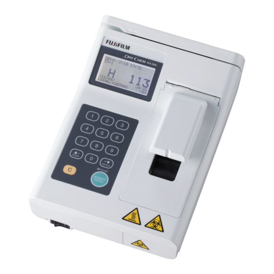
FUJI DRI-CHEM NX10N
This Manual describes details on how to operate
the FUJI DRI-CHEM NX10N and cautions to be
observed when operating it. Please read this
manual thoroughly before actually operating
the FUJI DRI-CHEM NX10N. After reading
this manual, store it nearby the FUJI DRI-
CHEM NX10N so that you can see it whenever
necessary.
EN
Safe Usage and
Handling Precautions
Component Names
and Functions
Principles of
Operation
Operations
Periodic Maintenance
Quality Control
Troubleshooting
Mode Settings and
Functions
Other Functions
Specifications/
Consumables
Glossary
7th Edition
897N120152H April 2022
1
2
3
4
5
6
7
8
9
10
11
Advertisement
Table of Contents
Troubleshooting

Related Manuals for FujiFilm DRI-CHEM NX10N


Summary of Contents for FujiFilm DRI-CHEM NX10N
- Page 1 Other Functions Specifications/ Consumables Glossary This Manual describes details on how to operate the FUJI DRI-CHEM NX10N and cautions to be observed when operating it. Please read this manual thoroughly before actually operating the FUJI DRI-CHEM NX10N. After reading 7th Edition...
- Page 3 Installation may only be conducted by authorized service personnel. <Intended Purpose> The FUJI DRI-CHEM NX10N is an in vitro diagnostic medical device to automatically quantitate ammo- nia in blood based on a colorimetric end-point with reflectance photometry, using the FUJI DRI-CHEM SLIDEs.
-
Page 5: Table Of Contents
Contents INTRODUCTION Contents 1. Safe Usage and Handling Precautions ............1-1 1.1 Definition of Specific Safety Precautions ...............1-1 1.2 Precautions Before Operating This Equipment ............1-1 1.3 Biohazards and Disposal ..................1-2 1.4 Explosive Hazards ....................1-2 1.5 Electrical Hazards ....................1-2 1.6 Electromagnetic Compatibility (EMC) ..............1-3 1.7 Moving Parts ......................1-3 1.8 Installation Site Requirements ................1-4 1.9 Test Results for Diagnosis ..................1-5... - Page 6 Contents 4. Operations ....................4-1 4.1 Preparations......................4-1 4.1.1 List for Daily Maintenance before Use ..................4-1 4.1.2 Preparations before Turning the Power on (Daily Maintenance before Use #1) ....4-1 4.1.3 Turning the Power on (Daily Maintenance before Use #2) ...........4-2 4.2 Measurements .......................4-4 4.3 Daily Maintenance after Use ..................4-8 4.4 QC Card System ....................4-9 4.5 Connecting to External Devices ................4-10...
- Page 7 Contents 8. Mode Settings and Functions ..............8-1 8.1 Mode Function List and Mode Selection ..............8-1 8.1.1 Mode List ..........................8-1 8.1.2 How to Select Each Mode .....................8-2 8.2 Mode 0 - Changing Mode Type <Normal> .............8-4 8.3 Mode 1 - Turning on the Control Mode (a, b canceled) <Normal> ......8-5 8.4 Mode 2 - Setting Date and Time <Normal>...
- Page 8 Contents 897N120152H FDC NX10N Instruction Manual 04.2022...
-
Page 9: Safe Usage And Handling Precautions
1 Safe Usage and Handling Precautions 1. Safe Usage and Handling Precautions This section contains safety precautions which must be followed for the safe operation of the FUJI DRI- CHEM NX10N (henceforth, the FDC NX10N). Before using this equipment, please read this chapter carefully and follow the precautions given, so that you can operate it correctly. -
Page 10: Biohazards And Disposal
1 Safe Usage and Handling Precautions 1.3 Biohazards and Disposal WARNING: As used (contaminated) consumables (e.g., slides, tips, and sample containers) and contaminated swabs or cloths used for cleaning the equipment are infectious waste, process the waste correctly in compliance with any applicable regulations in your country, such as by incineration, melting, sterilization or disinfection. -
Page 11: Electromagnetic Compatibility (Emc)
1 Safe Usage and Handling Precautions CAUTION: Connect the AC adapter to the connector for AC adapter connection. If AC adapter is not used, unplug the AC power cable from the receptacle. Do not leave the equipment alone in an energized state for an extended period of time. NOTE: Turn off the equipment before removing the AC adapter. -
Page 12: Installation Site Requirements
1 Safe Usage and Handling Precautions 1.8 Installation Site Requirements CAUTION: Avoid the following installation sites: - Places where spills or water leakage may occur. - Places where the equipment is exposed to direct sunlight. - Places near sources of heat such as heaters. - Places where the temperature may drastically change. -
Page 13: Test Results For Diagnosis
1 Safe Usage and Handling Precautions 1.9 Test Results for Diagnosis CAUTION: Use the AC adapter supplied with this equipment. Failure to do so may lead to the failure of the equipment or inaccurate test results. IMPORTANT: Make a diagnosis in a comprehensive manner, considering other relative test results or clinical situation. Always use the FUJI DRI-CHEM SLIDEs (NH -WII / NH -PII) and samples corresponding to those... -
Page 14: Fuji Dri-Chem Slides (Nh -Wii / Nh -Pii)
1 Safe Usage and Handling Precautions 1.11 FUJI DRI-CHEM SLIDEs (NH -WII / NH -PII) NOTE: (Henceforth, FUJI DRI-CHEM SLIDE is shortened into “slide” in this manual.) WARNING: Do not touch used slides with bare hands as this may cause contamination. If any part of the body comes in contact with used slides, immediately rinse the contaminated body part thoroughly under run- ning water and then use ethyl alcohol as a disinfectant. -
Page 15: Fuji Clean Tips
1 Safe Usage and Handling Precautions 1.14 FUJI CLEAN TIPS NOTE: Henceforth, FUJI CLEAN TIPS can be shortened into “tip”. Manual pipetting is used with the FDC NX10N. The proprietary tip from FUJI CLEAN TIPS is required to be attached to a pipette. IMPORTANT: Do not touch the tip-end. -
Page 16: Symbols
1 Safe Usage and Handling Precautions 1.16 Symbols Sign Description Warning, Caution, Important, consult documents Biological risks High temperature caution Power switch Fragile item, handle carefully Protect from rain This way up Stacking limitation Temperature limitation Manufacturer Serial number Country of manufacture Date of manufacture Authorized representative in the European Community In vitro diagnostic medical devices... - Page 17 1 Safe Usage and Handling Precautions Sign Description Importer Consult Instructions for Use Unique device identifier Near-patient testing 897N120152H FDC NX10N Instruction Manual 04.2022...
- Page 18 1 Safe Usage and Handling Precautions 1-10 897N120152H FDC NX10N Instruction Manual 04.2022...
-
Page 19: Component Names And Functions
2 Component Names and Functions 2. Component Names and Functions 2.1 Component Names QC card reader Display Pipette guide Keyboard Slide loading Power switch part Pipette cover Disposal box [Measurement Part] Pipette cover Reference black plate / Reference white plate Upper heater Transfer frame Photometer... - Page 20 2 Component Names and Functions USB (A type) x 2 Connector for AC adapter connection Air Filter USB (B type) AC Adapter mark is the mark of the Class II device. 897N120152H FDC NX10N Instruction Manual 04.2022...
-
Page 21: Names And Functions Of Display And Keyboard
2 Component Names and Functions 2.2 Names and Functions of Display and Keyboard 2.2.1 Display The display shows operation procedures or equip- ment status. [ID] Displays sample ID. [LotNo.] Displays the slide production lot number by reading the QC card. [Countdown] Displays remaining time (mm : ss) before the test is complete. - Page 22 2 Component Names and Functions Numeric keys The numeric keys are used for inputting num- bers such as sample ID, compensation coeffi- cients, and date. MODE/▲(Up)/ (Period) key MODE The MODE key is used for switching to the MODE mode selection dialog when [Ready] or [Warming up] appears on the display.
-
Page 23: Principles Of Operation
3 Principles of Operation 3. Principles of Operation This section provides an overview of the operations and the processes of the analyzer to obtain test results. Refer to Section 4 for detailed operation procedures. 3.1 Slide Loading The analyzer can compensate for the differences between the slide production lots by reading the QC card in the box of slides. - Page 24 3 Principles of Operation 897N120152H FDC NX10N Instruction Manual 04.2022...
-
Page 25: Preparations Before Turning The Power On (Daily Maintenance Before Use #1)
4 Operations 4. Operations 4.1 Preparations 4.1.1 List for Daily Maintenance before Use According to Section 4.1.2 and Section 4.1.3, please perform the daily maintenance before use. Item Contents Reference section Dispose of used slides to empty the disposal Cleaning disposal box 4.1.2 (1) box. -
Page 26: Turning The Power On (Daily Maintenance Before Use #2)
4 Operations 4.1.3 Turning the Power on (Daily Maintenance before Use #2) Operating procedures (1) Make sure that the AC power cable and the AC adapter are connected properly. (2) Make sure that each device is connected properly when using external devices (host computer, sample barcode reader, external printer). - Page 27 4 Operations (4) When the initialization is completed, the mes- sage shown on the left is displayed for about five 2015-12-02 10:00 seconds. Open the disposal box and dispose of used slides if they have not been discarded. IMPORTANT: If the disposal box is full, errors may occur in slide Check slide ejection transferring and produce inaccurate test results.
-
Page 28: Measurements
4 Operations 4.2 Measurements WARNING: When handling samples (whole blood or blood plasma), always follow biohazard procedures (e.g., wearing gloves, lab coat, and safety goggles), referring to the sample handling rules at your facility. If any part of the body comes in contact with samples, immediately rinse the contaminated body part thoroughly under run- ning water and then use ethyl alcohol as a disinfectant. - Page 29 4 Operations (3) Input a sample ID (if required). For information on how to input, refer to Section 4.7 (P4-13). 2015-12-02 10:00 When the sample barcode reader (optional) is R e a d y connected, the sample ID can be easily input by barcode reading instead of manual key input.
- Page 30 4 Operations IMPORTANT: After placing the drop, press the START key within three seconds to start the test. If the placed sample is left for a long time, it may produce inaccurate test results. The pipette cover must be always closed when the test is carried out.
- Page 31 4 Operations (7) Press the START key to start the test. START The message shown on the left appears during the test, and the remaining time is displayed. 2015-12-02 10:00 IMPORTANT: M e a s u r i n g Do not insert a slide to the slide loading part.
-
Page 32: Daily Maintenance After Use
4 Operations 4.3 Daily Maintenance after Use (1) Make sure that measurements and mode opera- tions are not in progress. NOTE: Do not turn off the power during measurement processes and mode operations. Otherwise, physical damage may occur to data in the equipment. -
Page 33: Qc Card System
4 Operations 4.4 QC Card System (1) Overview The QC card system compensates for variations between production lots of FUJI DRI-CHEM SLIDEs and ensures uniform performance. (2) Inputting Lot Compensation Coefficients Using the QC Card The lot compensation coefficients are magnetically recorded on QC cards, and one or more QC cards are packed with each box of slides. -
Page 34: Connecting To External Devices
4 Operations 4.5 Connecting to External Devices The analyzer can communicate with the host computer, the sample barcode reader, and/or the external print- er via the USB connector. IMPORTANT: When connecting the analyzer to the host computer, sample barcode reader, and/or external printer, complete the connections before turning on the analyzer. -
Page 35: Sample Barcode Reader
4 Operations 4.6 Sample Barcode Reader By using the sample barcode reader, the sample ID can be easily input. When using the sample barcode reader, connect it to the analyzer before turning on the analyzer. IMPORTANT: Depending on the printing quality of barcode labels or malfunction of the sample barcode reader, wrong bar- code data may be read. - Page 36 4 Operations (3) After completing the reading, a beep will be heard and the sample ID will be displayed. 2015-12-02 10:00 IMPORTANT: R e a d y Make sure that the barcode data (sample ID) shown ID=3333455 on the display is correct. NOTE: When rereading the barcode data, press the LotNo.=123456 <P>...
-
Page 37: Sample Id
4 Operations 4.7 Sample ID When turning on the power for the first measure- ment, the sample ID “1” is automatically displayed. 2015-12-02 10:00 R e a d y ■ ID=1 LotNo.=123456 <P> When changing the sample ID, input a sample ID by When a sample ID has entered by numeric keys: numeric keys or by the sample barcode reader (op- tional). - Page 38 4 Operations [Sample ID Automatic Updating Function] The next sample ID is automatically updated to “(Sample ID used in the most recent measurement) + 1”. NOTE: When a sample ID is entered by the sample barcode reader (optional), it is not updated automatically. The next sample ID becomes “(Latest sample ID not entered by the sample barcode reader) + 1”.
-
Page 39: Periodic Maintenance
5 Periodic Maintenance 5. Periodic Maintenance In order to keep the FDC NX10N performance at its best, perform the daily/periodic maintenance by users. WARNING: When performing maintenance (cleaning the analyzer), always follow biohazard procedures (e.g., wear- ing gloves, lab coat, and safety goggles). If any part of the body comes in contact with contaminated parts or swabs, immediately rinse the con- taminated body part thoroughly under running water and then use ethyl alcohol as a disinfectant. - Page 40 5 Periodic Maintenance 5.1 Periodic Maintenance <User daily/periodic maintenance> According to the following table, please perform daily/periodic maintenance by users. Check points Cleaning interval Procedure Photometer Monthly or when inaccurate test results occur Refer to Section 5.2 Slide loading part / transfer part Monthly or when they are dirty Refer to Section 5.3 Disposal box Monthly or when it is dirty...
-
Page 41: Cleaning The Photometer
5 Periodic Maintenance 5.2 Cleaning the Photometer Stains on the photometer, reference black plate and reference white plate largely affect test results. These parts should be checked and cleaned at least once a month. WARNING: Before cleaning the analyzer, always be sure to unplug the AC power cable, the USB cable and the like. Always wear gloves, lab coat, and safety goggles when you perform cleaning. -
Page 42: Cleaning The Slide Loading Part And The Slide Transfer Part
5 Periodic Maintenance 5.3 Cleaning the Slide Loading Part and the Slide Transfer Part Stains on the slide loading part, slide transfer part and upper heater may largely affect on test results. These parts should be checked and cleaned at least once a month. WARNING: Before cleaning the analyzer, always be sure to unplug the AC power cable, the USB cable and the like. -
Page 43: Cleaning The Disposal Box
5 Periodic Maintenance 5.4 Cleaning the Disposal Box Discard the used slides in the disposal box everyday or every 10 tests. Also, it should be cleaned at least once a month. WARNING: Before cleaning the analyzer, always be sure to unplug the AC power cable, the USB cable and the like. Always wear gloves, lab coat, and safety goggles when you perform cleaning. -
Page 44: Cleaning The Air Filter
5 Periodic Maintenance 5.5 Cleaning the Air Filter The air filter should be checked and cleaned at least once a month. WARNING: Before cleaning the analyzer, always be sure to unplug the AC power cable, the USB cable and the like. IMPORTANT: If the air filter is not cleaned, the temperature of the analyzer inside will increase, so that adverse effects on test results may occur. -
Page 45: Quality Control
6 Quality Control 6. Quality Control IMPORTANT: To maintain the accuracy of your test results, daily quality control is necessary. Perform quality control using control fluids. 6.1 Control Fluids Use the FUJI DRI-CHEM CONTROL QN (henceforth, the QN) for the FUJI DRI-CHEM SLIDEs to perform quality control. - Page 46 6 Quality Control 897N120152H FDC NX10N Instruction Manual 04.2022...
-
Page 47: Troubleshooting
7 Troubleshooting 7. Troubleshooting WARNING: When performing troubleshooting, always follow biohazard procedures (e.g., wearing gloves, lab coat, and safety goggles). If any part of the body comes in contact with contaminated parts, immediately rinse the contaminated body part thoroughly under running water and then use ethyl alcohol as a disinfectant. Seek medical assistance if necessary. -
Page 48: Troubleshooting
7 Troubleshooting (Supplement) About Measurement Range The relation between the measurement range (determination range) and the reference interval is as shown below. For details, refer to the “Instructions for Use” of the slides. NOTE: - Switching of the reference values such as “@” or “<, >” can be set by using the mode 9 shown at Mode 9 - Switch- ing Display Method for Values outside of the Determination Range of mode function. -
Page 49: Startup Errors
7 Troubleshooting 7.2 Troubleshooting NOTE: - To stop beeping when an error occur, touch the C (clear) key. - When an error occurs, the analyzer may terminate the measurement. When rerunning the sample, set the sample ID and a slide, and spot the sample again from the beginning to restart the measurement. 7.2.1 Startup Errors (1) When the analyzer does not start after the power switch is depressed to the [ | ] side: Check that the power cable and AC adapter are properly connected and then turn on the analyzer again. -
Page 50: Built-In Clock Errors
7 Troubleshooting Error code Error message Error status Solvent The circuit board has a Turn the power switch off and on. If E0306 ADC calibration ERR malfunction (signal error). the error still occurs, please contact Faulty controller your technical support (dealer) for Contact your dealer assistance. -
Page 51: Temperature Control Errors
7 Troubleshooting 7.2.7 Temperature control errors Error code Error message Error status Solvent Temperature of the Perform the following: E1500 Upper temp not ready photometer or the upper (a) Make sure the room temperature Check room temp or heater is not within the is between 15 - 32°C (59 - 89°F). -
Page 52: Host Computer Connection Errors
7 Troubleshooting Error code Error message Error status Solvent Temperature control of the Perform the following: E1550 Upper temp range ERR photometer or the upper (a) Make sure the room temperature Check room temp heater has a malfunction. is between 15 - 32°C (59 - 89°F). If Turn power SW OFF it is out of the range, air-condition ****** [deg]... -
Page 53: Data Errors
7 Troubleshooting 7.2.10 Data errors Error code Error message Error status Solvent These errors are related to Please contact your technical support E3000- Master/BackupFile ERR the data in the equipment. (dealer) for assistance. E3050 Specific parameters Contact your dealer etc. 7.2.11 QC card reading errors Error code Error message... - Page 54 7 Troubleshooting 897N120152H FDC NX10N Instruction Manual 04.2022...
-
Page 55: Mode Function List And Mode Selection
8 Mode Settings and Functions 8. Mode Settings and Functions 8.1 Mode Function List and Mode Selection Mode functions are used for changing functions, inputting parameters, etc. NOTE: If the external printer is connected, the new selection of mode operation can be printed. 8.1.1 Mode List There are 2 kinds of modes: one is the administrator mode, which can only be operated by administrators;... -
Page 56: How To Select Each Mode
8 Mode Settings and Functions 8.1.2 How to Select Each Mode (1) To enter a mode operation: There are 2 ways to select a mode: - Selecting the desired mode by scrolling ===> (a) - Inputting the desired mode number directly ===>... - Page 57 8 Mode Settings and Functions (b) Inputting the desired mode number directly In the display conditions shown at the left, press the MODE key to display the mode number in- put dialog. MODE Input a Mode No. from the keyboard and press the ENTER key to display the first dialog of the mode.
-
Page 58: Mode 0 - Changing Mode Type
8 Mode Settings and Functions 8.2 Mode 0 - Changing Mode Type <Normal> The important modes, which affect test results such as Mode 10 (correlation coefficients settings), can only be operated in the administrator mode. (1) Enter into Mode 0. START MODE (2) Select the administrator mode. -
Page 59: Mode 1 - Turning On The Control Mode (A, B Canceled)
8 Mode Settings and Functions 8.3 Mode 1 - Turning on the Control Mode (a, b canceled) <Normal> This mode is used for daily measurements of control fluids (FUJI DRI-CHEM CONTROL QN), which is used for precision management, and for control surveys. When the control mode is selected, the analyzer calculates the concentration with the correlation coefficients for all tests reset to a=1 and b=0. -
Page 60: Mode 2 - Setting Date And Time
8 Mode Settings and Functions 8.4 Mode 2 - Setting Date and Time <Normal> This mode is used to set the date and time. (1) Enter into Mode 2. START MODE (2) Input date. [To set date] Example Dec. 02 2015 NOTE: If an input value is outside the effective range, a beep sounds and the display returns to re-input status. - Page 61 8 Mode Settings and Functions (3) Input time. [To set Time] Example 10:00 NOTE: If an input value is outside the effective range, a beep sounds and the display returns to re-input status. (a) Input hour from the keyboard and press the Hour(10) START ENTER key.
-
Page 62: Mode 3 - Setting Date Display Format
8 Mode Settings and Functions 8.5 Mode 3 - Setting Date Display Format <Normal> This mode is used to set the date display format. (1) Enter into Mode 3. START MODE (2) Select a date display format. Select [Y Y Y Y-MM-DD], [MM-DD-Y Y Y Y] or [DD-MM-YYYY] by the scroll keys , then press the ENTER key. -
Page 63: Mode 4 - Checking Test Data
8 Mode Settings and Functions 8.6 Mode 4 - Checking Test Data <Normal> This mode is used to check the routine test data or control data. (1) Enter into Mode 4. START MODE NOTE: After a beep sounds and the message is dis- played about two seconds, the analyzer quits the mode operation: If the test data do not exist. - Page 64 8 Mode Settings and Functions (3) When the host computer is connected, transmit the test data. Press the ENTER key to start the transmission. (a) Select [Transmit data]. Select [Transmit data] by the key, and then press the ENTER key. If the host computer and the printer are con- nected to the analyzer, select [Transmit data], and then press the ENTER key.
- Page 65 8 Mode Settings and Functions (4) When the external printer is connected, print the test data. Press the ENTER key to start printing. (a) Select [Print data]. Select [Print data] by the key, and then press the ENTER key. If the host computer and the printer are con- nected to the analyzer, select [Print data] and then press the ENTER key.
-
Page 66: Mode 5 - Printing All
8 Mode Settings and Functions 8.7 Mode 5 - Printing all <Normal> This mode is used to perform batch printing of routine test data or control data. NOTE: If the external printer is connected, the data can be printed. (1) Enter into Mode 5. START MODE NOTE: After a beep sounds and the message is dis-... - Page 67 8 Mode Settings and Functions (Supplement) Example printout Data printing for Select the routine test data. Select the control data. when the test data is broken. 897N120152H FDC NX10N Instruction Manual 04.2022 8-13...
-
Page 68: Mode 6 - Displaying/Printing Out Error Logs
8 Mode Settings and Functions 8.8 Mode 6 - Displaying/Printing out Error Logs <Normal> This mode is used to display/print out error logs memorized in the analyzer. (1) Enter into Mode 6. START MODE To display the error logs: ........(2) To print the error logs: ........... - Page 69 8 Mode Settings and Functions (3) When the external printer is connected, print the error logs. Select [Print] (a) Select [Print] using the using the key and press MODE RERUN the ENTER key. START NOTE: To cancel printing, press the C (Clear) key. Printing all is complete After printing the error logs, the analyzer quits...
-
Page 70: Mode 7 - Displaying Temperature
8 Mode Settings and Functions 8.9 Mode 7 - Displaying Temperature <Normal> This mode is used to display the upper and lower heater temperature, photometer LED temperature, and temperature of inside the analyzer. (1) Enter into Mode 7. START MODE (2) After the temperature is displayed for about five seconds, the mode is terminated. -
Page 71: Mode 8 - Unit Conversion [Unit (A) / Unit (B) Switch]
8 Mode Settings and Functions 8.10 Mode 8 - Unit Conversion [Unit (A) / Unit (B) Switch] <Admini.> This mode is used to switch the results printing unit between Unit (A) and Unit (B) (1) Enter into Mode 8. START NOTE: After a beep sounds and the message is dis- MODE played about two seconds, the analyzer quits... -
Page 72: Mode 9 - Switching Display Method For Values Outside Of
8 Mode Settings and Functions 8.11 Mode 9 - Switching Display Method for Values outside of the Determination Range <Admini.> This mode is used to switch the display method for results outside of the determination range for all tests. NOTE: As for the relation between the measurement range (determination range) and the reference interval, refer to the “7.1.2 Test Result Indications Table”. -
Page 73: Mode 10 - Correlation Coefficients (A, B) Settings
8 Mode Settings and Functions 8.12 Mode 10 - Correlation Coefficients (a, b) Settings <Admini.> This mode is used to input or reset correlation coefficients. For further details, refer to the Description of the Correlation Function at the end of this section. IMPORTANT: The input of incorrect (a, b) causes incorrect test results. - Page 74 8 Mode Settings and Functions (3) Select correlation data. Display when all tests are reset (a) Press the ENTER key. Display with some ongoing tests START (b) Select [Input] and press the ENTER key. Select [Input] using the MODE RERUN START (c) Select [Input] and press the ENTER key.
- Page 75 8 Mode Settings and Functions Move the cursor using the MODE RERUN M10 Correlation data Input ■ Input a new value for coefficient (d) Input a new value for coefficient “a”. “a” : (example) a=1.200 The current value is displayed. Input a new value for “a”...
- Page 76 8 Mode Settings and Functions (4) Reset coefficients. M10 Correlation data Input Reset (a) Select [Reset] and press the ENTER key. Select MODE RERUN START M10 Correlation data Reset Not reset M10 Correlation data Reset Not reset (b) Select whether to reset the coefficients or not. Select MODE RERUN...
- Page 77 8 Mode Settings and Functions IMPORTANT: Description of the Correlation Function This function is designed to determine the correlation between the measured data obtained using the FDC NX10N and the data obtained using the conventional measuring method with your own instruments. On the X-axis, the measured data obtained using Y=aX+b your instruments are plotted and on the Y-axis, the...
- Page 78 8 Mode Settings and Functions (4) Measurement range after inputting coefficients (a, b) Depending on the values input for (a, b), the apparent limits of the measurement range will shift as follows. If a = 1 and b = 0 (Y = X), the measurement range is 10-500 μg/dl.
-
Page 79: Mode 11 - Lot Compensation Coefficients (C, D, E) Settings
8 Mode Settings and Functions 8.13 Mode 11 - Lot compensation coefficients (c, d, e) settings <Admini.> This mode is used to input the values (c, d, e) on a QC card packed with slides. This mode is used when the data is difficult to be read directly from a QC card that was lost or damaged. - Page 80 8 Mode Settings and Functions (b) Input a value “c” and then press the ENTER key. Input a new value for coefficient “c” : (example) c = -4.560 MODE RERUN START (c) Input a value “d” and then press the ENTER key. Input a new value for coefficient “d”...
- Page 81 8 Mode Settings and Functions M11 Lot coefficients (e) Input a value for year and then press the Input ENTER key. ■ Exp(Y)=2013=>20 Exp(M)=05=> NOTE: Input the last 2 digits of year Input a new value for expiration year (Y): (example) (Y) = 15 START (f) Input a value for month and then press the...
-
Page 82: Mode 12 - Reference Interval Settings
8 Mode Settings and Functions 8.14 Mode 12 - Reference interval settings <Admini.> This mode is used to set reference intervals. (1) Enter into Mode 12. START MODE NOTE: After a beep sounds and the message is dis- played about two seconds, the analyzer quits the mode operation: If the QC card information does not exist. - Page 83 8 Mode Settings and Functions (3) Input a reference interval. NOTE: To reset in the reference interval settings, input Display when all tests are reset “0” for a lower limit value and an upper limit value according to the following procedure. Display with some ongoing tests (a) Press the ENTER key.
- Page 84 8 Mode Settings and Functions Move the cursor using the START Input a new value for lower limit: (d) Input a lower limit value. (example) Lower = 12 After the input, press the ENTER key. START NOTE: If the ENTER key is pressed without input of the new lower limit, the current value is set.
- Page 85 8 Mode Settings and Functions (4) Select whether or not to add the reference in- terval on the test results. (a) Select [Add to results?] for setting whether or not to Select MODE RERUN add the reference interval on the test results. START Select (b) Select [YES] or [NO] from the menu using the...
-
Page 86: Mode 13 - Selecting Language
8 Mode Settings and Functions 8.15 Mode 13 - Selecting Language <Admini.> This mode is used to select a language for display and printout. (1) Enter into Mode 13. START MODE (2) Select a language. (a) Select a language using the keys and press the ENTER key. -
Page 87: Mode 14 - Beep Sound Settings
8 Mode Settings and Functions 8.16 Mode 14 - Beep Sound Settings <Admini.> This mode is used to change the beep sound settings (error warning or end of a test). (1) Enter into Mode 14. START MODE (2) Select [Error sound] or [Test end sound]. Select a menu [Error sound] or [Test end sound] using the keys, and press the... -
Page 88: Mode 15 - Liquid Crystal Contrast Adjustments
8 Mode Settings and Functions 8.17 Mode 15 - Liquid crystal contrast adjustments <Admini.> This mode is used to adjust the display brightness. (1) Enter into Mode 15. START MODE (2) Adjust the display brightness. (a) By moving the shaded part (cursor) using the keys, the brightness will change. -
Page 89: Mode 16 - Editing Sample Id
8 Mode Settings and Functions 8.18 Mode 16 - Editing sample ID <Admini.> This mode is used to edit sample IDs memorized in the analyzer memory. The edited data can be sent to host computer. The test results include the routine test data and control data. (1) Enter into Mode 16. - Page 90 8 Mode Settings and Functions (3) Input new numbers for the sample ID. (Example) ID=1111111111111 Input a new sample ID and press the ENTER ID=1234567890123 key. NOTE: If the C (clear) key is pressed when a cursor M16 Edit ID is located in the [NEW] line having no data in- ID OLD=1111111111111 put, the analyzer returns to the data selection...
-
Page 91: Mode 31 - Administrator Password Setting
8 Mode Settings and Functions 8.19 Mode 31 - Administrator password setting <Admini.> The administrator password can be changed here. (1) Enter into Mode 31. START MODE (2) Edit the password using numeric keys and the C (Clear) key. M31 Admin password Password= NOTE: A password can be 4 or 5 numeric characters long. - Page 92 8 Mode Settings and Functions 8-38 897N120152H FDC NX10N Instruction Manual 04.2022...
-
Page 93: Other Functions
9 Other Functions 9. Other Functions 9.1 Data Communication The FDC NX10N can transmit test results to the host computer (PC) which has already been approved by IEC/UL60950-1 or IEC/UL62368-1. To communicate, preparations such as the installation of the specified device driver are required for the host computer. - Page 94 9 Other Functions 897N120152H FDC NX10N Instruction Manual 04.2022...
-
Page 95: Specifications/Consumables
10 Specifications/Consumables 10. Specifications/Consumables 10.1 Specifications and Bundled Items 10.1.1 Specifications Test method: Reflectance photometry, using the FUJI DRI-CHEM SLIDEs. Test item: Ammonia Slide: FUJI DRI-CHEM SLIDE NH -WII or NH -PII Warming up time: Approx. 5 minutes (at room temperature of 25°C / 77°F) Incubation temperature: 37°C (98°F) Incubation time:... -
Page 96: Bundled Items
10 Specifications/Consumables 10.1.2 Bundled Items AC adapter Ferrite core Instruction manual Installation quick guide NOTE: An AC power cable is not supplied as a bundled item. Please prepare an AC power cable conforming to the specifications below: <The requirements of the cable specifications for the FDC NX10N> Power voltage: 200V-240V Requirements of the plug/connector: AC250V 2.5A... -
Page 97: Consumables And Optional Item
10 Specifications/Consumables 10.2 Consumables and Optional Item For purchasing consumables or optional item listed below, please contact the dealer from whom you pur- chased the FDC NX10N. 10.2.1 Consumables Name Package FUJI DRI-CHEM SLIDE NH -WII 24 slides per box FUJI DRI-CHEM SLIDE NH -PII 24 slides per box... - Page 98 10 Specifications/Consumables 10-4 897N120152H FDC NX10N Instruction Manual 04.2022...
-
Page 99: Glossary
11 Glossary 11. Glossary Glossary of the display & printout messages NOTE: - Because the display spaces and printouts are limited, some abbreviations are used. - Periods will not be used after abbreviations on the display and printout messages. Abbreviation Meaning Analog/Digital after... - Page 100 11 Glossary 11-2 897N120152H FDC NX10N Instruction Manual 04.2022...
- Page 102 26-30, NISHIAZABU 2-CHOME, MINATO-KU, TOKYO 106-8620, JAPAN https://www.fujifilm.com/ Balcke-Duerr-Allee 6, 40882 Ratingen, Germany Oudenstaart 1, 5047 TK Tilburg, The Netherlands...
Need help?
Do you have a question about the DRI-CHEM NX10N and is the answer not in the manual?
Questions and answers