FujiFilm FCR XG-1 Service Manual
Hide thumbs
Also See for FCR XG-1:
- Operation manual (100 pages) ,
- Operation manual (88 pages) ,
- Service manual (20 pages)

Related Manuals for FujiFilm FCR XG-1


Summary of Contents for FujiFilm FCR XG-1
- Page 1 FUJI COMPUTED RADIOGRAPHY FCR XG-1 CR-IR346RU Service Manual Document No. 010-051-06 1 st Edition - Oct. 10, 2000 Revised Edition - April 20, 2002 Fuji Photo Film Co., Ltd. Printed in Japan...
- Page 2 The relationship between mR (milliroentgen), which is the unit of radiation, and µC/kg (micro-coulomb/kilogram), which is the SI derived unit of radiation, is as follows. 1 mR = 0.258 µC/kg ® is a registered trademark of Fuji Photo Film Co., Ltd. <No part of this manual may be reproduced or transmitted.>...
- Page 3 Getting Started I Scope This Service Manual is applicable to Fuji Computed Radiography CR-IR346RU. The ma- chine is categorized as Class 1 according to IEC classification. I Notation of Unit Symbols For notation of unit symbols, metric units set forth in the International Systems of Units (SI) are used, as a rule.
- Page 4 I Notation of Symbols • Check/Adjustment indicator: Indicates that it is necessary to check or adjust the installa- tion location when the part or component removed is to be reinstalled. This indicator is placed in the illustration that depicts the CHECK procedures for removing the parts and components.
- Page 5 Safety Precautions Warnings and cautions regarding the procedures should be observed to avoid possible physical hazards and serious accidents that may occur during installation and servicing. Labels that describe relevant precautions are attached on the machine. The instructions on such labels should also be observed during procedures. Working Precautions I Power Supply G Unless otherwise instructed in the Service Manual, be sure to turn OFF the power of the...
- Page 6 I Optical Parts Observe the following rules when servicing the optical parts. Otherwise, the image quality may be degraded. G Before removing the protective housings, be sure to turn OFF the high-voltage switch (HV switch). If the machine is powered ON with any of the protective housings removed, the photomultiplier will be damaged.
- Page 7 Precautions Against Laser Radiation As indicated by the Certification and Indication Label attached on the rear cover of the machine for overseas use, the machine complies with the U.S. Federal Regulations concerning laser safety. The image reader incorporates a laser with a maximum output of 50 mW (Class 3B, semiconductor laser wavelength of 660 nm, red visible light), but you will not be exposed to any hazard if you perform tasks as instructed in this manual.
- Page 8 I Protective Housings Against Laser Exposure Even when the protective housings are removed for servicing, laser beams will never leak out from the machine unless the optical path is intentionally changed. However, if the optical path is changed inadvertently during optics-related procedures, the service engineer or other people around the machine may be possibly exposed to laser radiation.
- Page 9 Safety Labels and Other Labels 2.3.1 Laser Precaution Labels I Precaution Label Attachment Locations Below are illustrated the protective housings and attachment locations of laser precaution labels, as specified in Part 1-J, Federal Regulations Code “Title 21” issued by the FDA of the U.S.
- Page 10 HHS Certification and Identification Label HHS Label #1 EN 60825-1: 1996 HHS Label #1 Class 1 Product Label EN 60825-1: 1996 EN 60825-1: 1996 Class 3B Panel Label Class 3B Panel Label HHS Label #2 FR6H0007.EPS G Scanning Optics Unit EN 60825-1: 1996 Warning Label FR6H0001.EPS...
- Page 11 0.10 I List of Precaution Labels G HHS Certification and Identification Label F U J I P H O T O F I L M C O . , L T D . 2 6 - 3 0 , N I S H I A Z A B U 2 - C H O M E , M I N A T O - K U , 2 6 - 3 0 , N I S H I A Z A B U 2 - C H O M E , M I N A T O - K U , T O K Y O 1 0 6 - 8 6 2 0 , J A P A N T O K Y O 1 0 6 - 8 6 2 0 , J A P A N...
- Page 12 0.11 G EN 60825-1: 1996 Class 3B Panel Label FR6H0015.EPS G EN 60825-1: 1996 Warning Label FR6H0010.EPS 010-051-00 CR-IR346RU Service Manual 0.11 10.10.2000 FM2887...
- Page 13 0.12 2.3.2 Other Labels I Label Attachment Locations Pharmaceutical Label Ratings Indication Label Manufacturer Label FR6H0011.EPS 010-051-01 010-051-00 CR-IR346RU Service Manual 0.12 08.30.2001 FM3058 10.10.2000 FM2887...
- Page 14 0.13 I List of Other Labels G Ratings Indication Label • For use in Japan FUJI PHOTO FILM CO., LTD. MADE IN JAPAN FUJI COMPUTED RADIOGRAPHY CR-IR 346RU MODEL ELECTRICAL RATING 50-60Hz INPUT 1-PHASE 100V~ MAX. INPUT CURRENT 405N2887 FR6H0023.EPS •...
- Page 15 0.14 Specifications of the Machine Product Abbreviations Product abbreviations Items Qty. Remarks CR IR346 RU# Machine-specific data FD 3.5-inch/1.44MB (for use in Japan) CD-ROM (for RU) For backup (installed prior to shipment) Label One set (RU exposure marker precaution labels) Label One set (inch and metric labels) Fuse set...
- Page 16 0.15 List of Optional Components Product abbreviations Items Qty. Remarks IR346 AC CORD RU power cable Japan, U.S., Canada, etc. 100-120V UL #(E) (for use in Japan and the U.S.) IR346 AC CORD RU power cable Germany, France, Spain, Sweden, etc. 200-240V E (for use in Europe, excluding the U.K.) IR346 AC CORD...
- Page 17 0.16 Dimensions, Weight, and Center of Gravity I Dimensions W550xD515xH1065 (mm) 1065 Unit: mm FR6H0002.EPS I Weight 155 kg approx. I Center of Gravity Height: 500 mm From the right-hand side: 275 mm From the rear: 242 mm 010-051-00 CR-IR346RU Service Manual 0.16 10.10.2000 FM2887...
- Page 18 0.17 Machine Moving and Fixing Means I Moving Means • Four two-wheel casters (variable direction/no brake) I Fixing Means • Four adjustable feet • One table (optional) adjustable feet • Two machine retainers (optional) • One table and two retainers (optional) Table Retainer FR6H0027.EPS...
- Page 19 0.18 Environmental Requirements I Atmospheric Requirements Operation Non-operation During transit 15–30 °C 0–45 °C -10–50 °C Temperature 10–90 % 10–90 % Relative 40–80 % humidity Without condensation Atmospheric 700–1,030 hPa 500–1,030 hPa pressure The above environmental requirements during non-operation and during transit do not apply to IPs (Imaging Plates). TR6H0001.EPS I Floor (Installation Area) Vibration Requirements Frequency: 10-55 Hz...
- Page 20 0.19 Electrical Specifications I Frequency 50Hz/60Hz, single-phase, common specification I Line Voltage For use in Japan: 100 VAC ±10% For use in the U.S.: 100-120 VAC ±10% For use in Europe: 200-240 VAC ±10% I Power Capacity 0.4 kVA I Power Cord 3m, with 3P plug/connector I Rated Amperage 100 VAC, 50/60Hz: 3A...
- Page 21 0.20 Other Specifications I Maximum Heat Generation Standby: 125 wh Operation: 230 wh I Noise Standby: 40 dB or less Operation: 60 dB or less Single-shot noise: 70 dB or less I Warm-up Time G Setup without power interlink (when the CR-IR346RU is booted in standalone fashion) 1 min approx.
- Page 22 0.21 Installation and Servicing Spaces REFERENCE The machine may be placed with its right and left sides and its rear against the walls. However, the front of the machine requires a space of 1,000 mm or more, and it is necessary to secure sufficient space around the machine to rotate it.
- Page 23 0.22 G When the machine is secured by the table and table retainers (without cassette pocket) Table Machine Front 1,000 or more Unit: mm FR6H0018.EPS G When the machine is secured by the table (full option) and table retainers (with cassette pocket) REFERENCE If the user uses small-size cassettes, the machine and table should be moved forward until the cassette is readily accessible.
- Page 24 0.23 I Servicing Space Sufficient space should be secured for servicing, as indicated below Space required for servicing Rear Machine Front Space required for rotation 1,000 Unit: mm FR6H0004.EPS REFERENCE If there is sufficient space to rotate the machine (800 mm around it), installation may be performed with 1,000 mm or more space secured only on one side.
- Page 25 0.24 CR-IR346RU Service Manual – Contents Machine Description (MD) Machine Overview ......................MD-2 1.1 Features ........................MD-2 1.2 System Configuration ....................MD-2 1.3 Overall Machine Configuration and Component Names ........MD-4 1.4 Machine Components ....................MD-6 1.4.1 Unit Locations ....................MD-6 1.4.2 Roller Locations and Conveyance Paths ...........
- Page 26 0.25 Mechanical Control Flows .................... MD-52 5.1 Initialization Process Flow ..................MD-52 5.1.1 Sensor ON ....................MD-56 5.1.2 Dust Removal Home Positioning .............. MD-60 5.1.3 Side-Positioning Grip Home Positioning ..........MD-66 5.1.4 Subscanning Grip Confirmation ............... MD-68 5.1.5 Side-Positioning Home Positioning ............MD-72 5.1.6 IP Search .....................
- Page 27 0.26 Troubleshooting (MT) Overview of Troubleshooting ..................MT-2 Flow of Troubleshooting ..................MT-2 Analysis and Check Flow Marks ................MT-3 How to View "1.4 Troubleshooting with Error Log" ..........MT-3 Troubleshooting with Error Log ................MT-4 1.4.1 Viewing the Error Log ................. MT-4 1.4.2 Determining the Error Code of the Encountered Trouble ......
- Page 28 0.27 11362 ..........................MT-80 11363 ..........................MT-81 11371, 11372 , 11373, 14372, 14373 ................MT-82 11380 ..........................MT-83 11387 ..........................MT-84 12313, 13314 ........................MT-85 12345 ..........................MT-86 12324, 14324 ........................MT-87 Error Code Analysis Flow (Scanner) ................MT-88 10230 ..........................MT-88 10231 ..........................
- Page 29 0.28 Troubleshooting for Failure to Update Software Versions or Failure to Back Up Machine Shipment Control Data ................. MT-113 Checking Connection between RU and CL ............. MT-113 7.1.1 Procedure for Checking Connection between RU and CL ....MT-113 7.1.2 Procedures for Recovering Connection between RU and CL ..... MT-113 Checking the FTP Server ..................
- Page 30 0.29 Checking the Actuators ....................MT-157 Checking the Scanner I/O .................... MT-161 14.1 Checking the Laser (LDD) ................. MT-161 14.2 Checking the Polygonal Mirror (POL) .............. MT-163 14.3 Checking the Start-Point Sensor (SYN) ............MT-165 14.4 Checking the Leading-Edge Sensor (SZ1) ............MT-167 14.5 Checking the Light-Collecting Unit (PMT) ............
-
Page 31: Table Of Contents
0.30 Checks, Replacement and Adjustment of Parts (MC) Check/Adjustment Procedures for Each Unit ............... MC-2 Table of Contents ......................MC-4 Removing and Reinstalling the Covers................. MC-8 Covers ........................MC-8 Removing and Reinstalling the Housings ..............MC-10 INV12B Board ...................... MC-10 Inverter Assembly .................... - Page 32 0.31 Removing and Reinstalling the Erasure Conveyor ............ MC-60 Erasure Conveyor ....................MC-60 Lamp Assembly ....................MC-62 Thermal Switch (TSWB1) ................... MC-66 Lamp ........................MC-68 Lamp Socket ......................MC-72 Thermistor ......................MC-76 Duct Box ......................MC-78 Cleaning Roller Assembly .................. MC-80 Timing Belt ......................
- Page 33 0.32 Removing and Reinstalling the Scanning Optics Unit ..........MC-132 Scanning Optics Unit..................MC-132 Removing and Reinstalling the Light-Collecting Unit ..........MC-136 Light-Collecting Unit..................MC-136 PMT12A Board ....................MC-142 Removing and Reinstalling the Subscanning Unit ..........MC-144 10.1 Subscanning Unit ..................... MC-144 10.2 Kapton®...
- Page 34 0.33 Replacing the Fuses and Fuse Locations ..............MC-238 12.1 MTH12A Board Fuses ..................MC-240 12.2 SCN12A Board Fuses ..................MC-241 12.3 SNS12A Board Fuses ..................MC-242 12.4 DRV12A Board Fuses ..................MC-243 Version Updating Procedures ..................MC-244 13.1 Procedures for Updating the Version of the PC-MUTL Software ....MC-246 13.1.1 Uninstall Procedures ................
- Page 35 0.34 Maintenance Utility (MU) Overview of RU Service Utility ..................MU-2 1.1 Features ......................... MU-2 1.2 Starting and Exiting the M-Utility ................ MU-3 1.3 Maintenance Utility Command Tree Diagram............. MU-7 Functions of the PC-MUTL ................... MU-12 2.1 CONNECTION TEST.................... MU-14 2.1.1 Procedures for Starting the M-Utility ............
- Page 36 0.35 2.5 BACKUP....................... MU-36 2.5.1 Backup Items ..................... MU-36 2.5.2 Procedures for BACKUP ................MU-37 2.5.3 Errors That May Occur during BACKUP and Their Probable Causes .. MU-38 2.6 RESTORE......................MU-39 2.6.1 Restore Items ..................... MU-39 2.6.2 Procedures for RESTORE ................. MU-40 2.6.3 Errors That May Occur during RESTORE and Their Probable Causes MU-41 2.7 UNINSTALL......................
- Page 37 0.36 Details of M-Utility ......................MU-72 [1] LOG ........................MU-72 [1-1] ERROR LOG....................MU-72 [1-1-1] DISPLAY....................MU-73 [1-1-2] SAVE TO FTP-SERV................MU-78 [1-1-3] CLEAR ...................... MU-79 [1-2] TRACE LOGS ....................MU-80 [1-2-1] DISPLAY....................MU-80 [1-2-2] SAVE ALL TRACE LOGS TO FTP-SERV..........MU-80 [1-2-3] CLEAR ALL TRACE LOGS ..............
- Page 38 0.37 [4] ELECTRICAL UTILITY..................MU-93 [4-1] AUTO MODE ....................MU-94 [4-1-1] ALL ......................MU-95 [4-1-2] CPU12A ....................MU-95 [4-1-3] SCN12A ....................MU-96 [4-1-4] INV12A ..................... MU-96 [4-1-5] SND12A ....................MU-97 [4-1-6] SUB CPU ....................MU-98 [4-2] BOARD TEST ....................MU-99 [4-2-1] CPU12A ....................
- Page 39 0.38 [5] SCANNER UTILITY.................... MU-112 [5-1] INITIALIZE ....................MU-113 [5-2] POLYGON ....................MU-114 [5-3] LASER ....................... MU-115 [5-4] SAVE INITIAL LDIF ................... MU-116 [5-4-1] GET DATA FROM SCN, SAVE TO RAM & FLASH & FTP-SERV..MU-116 [5-4-2] SAVE DEFAULT DATA TO RAM & FLASH & FTP-SERV ....MU-116 [5-5] HV STATUS ....................
- Page 40 0.39 [6] MECHANICAL UTILITY ..................MU-137 [6-1] MOTOR ...................... MU-137 [6-1-1] Parameter setup (For version A02 through A04) ....... MU-138 [6-1-1] Motor drive and stop (For A05 or later)..........MU-140 [6-1-2] Motor drive (for version A02 through A04) ......... MU-141 [6-1-2] Parameter setup (for version A05) ............
- Page 41 0.40 Service Parts List (SP) How to Use the Service Parts List ....................SP-2 01A COVER 1 ........................SP-6 01B COVER 2 ........................SP-8 FRAME .......................... SP-10 03A CASSETTE SET UNIT 1 ....................SP-12 03B CASSETTE SET UNIT 2 ....................SP-14 03C CASSETTE SET UNIT 3 ....................
- Page 42 0.41 BLANK PAGE 010-051-01 CR-IR346RU Service Manual 0.41 08.30.2001 FM3058 (1)
- Page 43 0.42 Preventive Maintenance (PM) Preventive Maintenance Program ................. PM-2 1.1 Preventive Maintenance Program List ..............PM-2 1.2 Notations of Intervals ................... PM-3 1.3 Preventive Maintenance Flow ................PM-4 Details of Maintenance Procedures ................PM-6 2.1 Opening the MAINTENANCE UTILITY Window ..........PM-6 2.2 Checking the Error Log ..................
- Page 44 0.43 Side-Positioning Conveyor ................... PM-30 10.1 Removing the Side-Positioning Conveyor ............PM-30 10.2 Side-Positioning Conveyor (Removing the Shock Absorbers) ...... PM-31 10.3 Side-Positioning Conveyor (Cleaning the Guides and Conveyance Rollers) ..........PM-32 10.4 Reinstalling the Side-Positioning Conveyor ............ PM-35 Subscanning Unit......................PM-36 11.1 Subscanning Unit (Cleaning the Cleaning Brushes) ........
- Page 45 0.44 Installation (IN) Specifications of Machine ....................IN-2 Installation Work Flowchart ....................IN-4 Preparation for Installation ....................IN-6 3.1 Precautions Regarding Installation............... IN-6 3.2 Unloading ........................ IN-7 3.3 Transfer........................IN-12 3.4 Temporary Placement ..................IN-13 3.5 Checking the Items Supplied ................IN-14 Installation Procedures ....................
- Page 46 0.45 Appendix 1. On-Site Relocation ....................IN-41 Preparation Prior to Relocation ..................IN-42 1.1 Securing the Light-Collecting Mirror ..............IN-42 1.2 Disconnecting the Cables ..................IN-42 Relocating the Machine ....................IN-43 Installation After Relocation ..................IN-43 3.1 Connecting the Cables ..................IN-43 3.2 Final Placement.....................
- Page 47 CR-IR346RU Service Manual Machine Description (MD)
-
Page 48: Table Of Contents
CR-IR346RU Service Manual – Contents Machine Description (MD) Machine Overview ......................MD-2 1.1 Features ........................MD-2 1.2 System Configuration ....................MD-2 1.3 Overall Machine Configuration and Component Names ........MD-4 1.4 Machine Components ....................MD-6 1.4.1 Unit Locations ....................MD-6 1.4.2 Roller Locations and Conveyance Paths ........... - Page 49 Mechanical Control Flows ................... MD-52 5.1 Initialization Process Flow ..................MD-52 5.1.1 Sensor ON ....................MD-56 5.1.2 Dust Removal Home Positioning .............. MD-60 5.1.3 Side-Positioning Grip Home Positioning ..........MD-66 5.1.4 Subscanning Grip Confirmation ............... MD-68 5.1.5 Side-Positioning Home Positioning ............MD-72 5.1.6 IP Search .....................
- Page 50 MD - 1 Machine Description (MD) Control Sheet Control Sheet Issue date Revision number Reason Pages affected 10/10/2000 New release (FM2887) All pages 08/30/2001 Revisions associated with release of MD-1–3, 5, 9–11, 14–21, version A05 (FM3058) 21.1–21.4, 32, 42, 43, 46, 47, 49, 02/20/2002 Revisions associated with release of MD-1–3, 13–39, 39.1–39.4, 52,...
-
Page 51: Machine Overview
MD - 2 Machine Overview Features I Features of the Machine G The CR-IR346RU is built in a more compact body designed with smaller scanning optics and light-collecting units. G The machine is network connectable via TCP/IP. G A commonly available power source may be used to supply power to the machine. System Configuration The CR-IR346RU may be configured in several combinations. - Page 52 MD - 3 I System Configuration Example (2) The machine is connected to the CL via a network. Image storage device (LF-C1 etc.) Network Switching hub Switching hub Straight cable Printer CR-IR346RU CR-IR346CL FR6H1302.EPS I System Configuration Example (3): RU Software A05 or Later A plurality of the machines (up to three) are connected to a single CL via a network.
-
Page 53: Overall Machine Configuration And Component Names
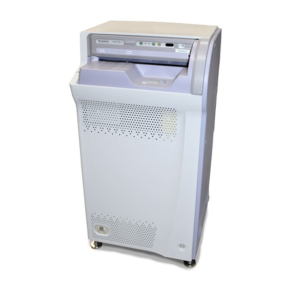
MD - 4 Overall Machine Configuration and Component Names I External View of Machine Top cover Display panel Right-hand side cover Front cover Power switch Reset switch FR6H1318.EPS Left-hand Upper rear cover side cover External device interface (I/F cable) Lower rear cover Power plug FR6H1319.EPS 010-051-00... - Page 54 MD - 5 I Display Panel Indicators 1. Cassette loading lamp 2. Processing status lamp 3. Cassette eject lamp 4. CALL lamp FUJI FILM FUJI 7. Power lamp 6. Erasure processing switch 5. Erasure processing indication display FR6H1305.EPS Name Lighting Functional description It is lit when the machine boots up normally.
-
Page 55: Machine Components
MD - 6 Machine Components 1.4.1 Unit Locations Cassette set unit (A) Cassette Erasure conveyor (B) Housing Side-positioning conveyor (C) Light-collecting unit Scanning optics unit Subscanning unit (Z) Controller FRONT FR6H1312.EPS 010-051-00 CR-IR346RU Service Manual MD - 6 10.10.2000 FM2887... -
Page 56: Roller Locations And Conveyance Paths
MD - 7 1.4.2 Roller Locations and Conveyance Paths FRONT : Grip roller : Conveyance path : IP conveyance sensor FR6H1313.EPS 010-051-00 CR-IR346RU Service Manual MD - 7 10.10.2000 FM2887... -
Page 57: I/O Locations And Functional Descriptions
MD - 8 1.4.3 I/O Locations and Functional Descriptions I I/O Locations (Sensors and Thermistors) Cassette set unit Erasure conveyor TSWB1 THB1 Side-positioning conveyor Subscanning unit FR6H1317.EPS 010-051-00 CR-IR346RU Service Manual MD - 8 10.10.2000 FM2887... - Page 58 MD - 9 I I/O List (Sensors and Thermistors) G Cassette set unit Symbol Name Type Function Cassette eject sensor PI (5mm) Detects that the cassette is ejected. Cassette IN sensor PI (5mm) Detects that the cassette is inserted. Hold sensor PI (5mm) Detects that the cassette is in the hold state.
- Page 59 MD - 10 I I/O Locations (Motors, Clutch, Solenoids, Pump, Valves, Solenoid Valve, Fans) Cassette set unit SVA1 Erasure conveyor CLA1 FAN3 SOLA1 Side-positioning conveyor FAN4 Subscanning unit (FMM) Controller SOLZ1 FAN2 FAN1 FR6H1314.EPS 010-051-01 CR-IR346RU Service Manual MD - 10 08.30.2001 FM3058...
- Page 60 MD - 11 I I/O List (Motors, Clutch, Solenoids, Pump, Valves, Solenoid Valve, Fans) G Cassette set unit Symbol Name Type Function Drives the suction cup arm and ejects the Suction cup drive motor Pulse motor cassette when the clutch is turned ON. Suction pump DC pump Sucks the IP.
-
Page 61: Board Locations
MD - 12 1.4.4 Board Locations LED board (LED12A) Inverter board (INV12B) Fluorescent lamp ballast (INV12A) Photomultiplier board (PMT12A) Leading-edge detection board (SED12A) Driver board (DRV12A) Sensor board (SNS12A) Scanner board (SCN12A) Connector board (CNN12A) Motherboard (MTH12A) CPU board (CPU12A) FR6H1316.EPS 010-051-00 CR-IR346RU Service Manual... -
Page 62: System Block Diagram
MD - 13 System Block Diagram I Power Supply System AC IN Network (85V–265V) or CL Power supply unit Connector board CNN12A +15V +24V CPU board CPU12A +24V Motherboard Image processing MTH12A frame memory Scanning optics unit +15V/24V Start-point +15V +24V detection board Driver board... - Page 63 MD - 14 I Signal System AC IN Network (85V–265V) or CL Power supply unit Connector board CNN12A +15V +24V CPU board CPU12A +24V Motherboard Image processing MTH12A frame memory Scanning optics unit Start-point detection board Driver board Sensor board Scanner board SYN12A DRV12A...
-
Page 64: Descriptions Of Software Control
MD - 15 Descriptions of Software Control Relationship between RU and CL This chapter describes exchanging of data between CL and RU, which is implemented when the CL is connected to the RU. N NOTE N In this chapter, “application”, “operating system”, and “RU configuration” are abbreviated as AP, OS, and RU-Config, respectively. - Page 65 MD - 16 G RU-AP (solid-line arrow) When RU-AP is installed, the RU-AP, RU-Config, and RU message file are copied to the CL. The RU-AP and RU-Config are copied to the flash ROM via the network. REFERENCE The RU message file is a file that contains details on the RU’s error information. It is used to cause the error code and error information detail to be displayed on the CL monitor by using, as a key, the error code generated on the RU.
- Page 66 MD - 17 I Data flow in normal process FLASH ROM Image data Backup memory FTP server Log data COMMON Memory (SRAM) RU-AP Image data RU-Config RU-Config RU-OS Log data Machine shipment control data RU-specific data FR6H1417.EPS G Image data The image data scanned from the IP is temporarily stored in the SRAM, and then transferred to the CL via the network.
- Page 67 MD - 18 I Data flow in backup and restore To backup and restore various types of data for the RU, RU M-Utility should be used. FLASH ROM FTP server Machine shipment control data COMMON RU-Config Machine shipment control data Backup memory RU-Config Log data...
-
Page 68: Mechanism For Updating Ru-Ap And Ru-Config
MD - 19 2.1.2 Mechanism for Updating RU-AP and RU-Config I How to Write the Flash ROM of the RU The RU itself is not equipped with any input device that allows for directly overwriting the RU- AP or RU-Config into the flash ROM of the RU. Thus, in order to overwrite the flash ROM of the RU, a personal computer (PC) connected to the network should be used. - Page 69 MD - 20 G For PC-MUTL version 1.1 or earlier (RU software: A06 or earlier) • After the PC-MUTL command is initially issued, the FTP server on the CL is overwritten. • After the RU is reset, the auto update feature during the RU bootup process allows the flash ROM of the RU to be overwritten from the FTP server on the CL.
- Page 70 MD - 21 [2] PC-MUTL commands G What PC-MUTL commands are used? Four commands for overwriting the flash ROM from the FTP server on the CL by use of the CL-PC: INSTALL, PREVIOUS VERSION, EDIT CONFIGURATION, and VERSION UP G Functions of the commands •...
- Page 71 MD - 22 Auto update feature The auto update feature is such that when the RU is booted, the dates of the RU-AP and RU-Config are compared between the FTP server on the CL and the flash ROM of the RU; and if they differ, the data is overwritten from the FTP server on the CL into the flash ROM of the RU.
-
Page 72: Ru Error Handling
MD - 23 RU Error Handling When an I/O (mechanism, scanner, etc.) abnormality occurs on the preceding models, the system used to shuts down handling then it as a fatal error. The RU, however, performs a retry process except when it is inoperative. G Retry operation •... -
Page 73: Diagnostics Sequence Upon Ru Bootup
MD - 24 2.2.2 Diagnostics Sequence upon RU Bootup There are two types of diagnostics processing upon RU bootup: “When booted by turning ON the power switch of the RU” and “When booted after the RU shutdown process”. I When Booted by Turning ON the Power Switch of the RU (1) Load (a) and (b) from the flash ROM on the CPU12A board into the DRAM memory. - Page 74 MD - 25 (6) Perform scanner diagnostics (including communication checks for the CPU12A and SCN12A boards). ➮ When the scanner diagnostics are completed normally, the “Main CPU LED” seg- ments on the CPU12A board flash right and left. REFERENCES • The date and time for any error code that has occurred until the date and time data was acquired from the CL is indicated as “0000.00.00.00.00:AA”.
-
Page 75: Ru Shutdown Process
MD - 26 2.2.3 RU Shutdown Process The RU shutdown process is such that the daily logs are saved into the FTP server, while the control section of the RU is in standby mode where its power remains ON to constantly monitor the status of the CL. -
Page 76: Descriptions Of Electrical Operations
MD - 27 Descriptions of Electrical Operations Power Supply Voltage Output Detection Function To facilitate early recovery from a failure, the RU incorporates the power supply voltage output detection function, which offers the following features: • Each load circuit incorporates a fuse that servers to isolate a fault. •... - Page 77 MD - 28 G CCR overcurrent protection circuit block diagram CNN12A CPU12A +5V circuit SCN12A A21P A22P SED12A +15V 1.5AT H 12P H 12 1.5AT H14P H 14 1.5AT J12P Power supply SYN12A -15V SLOT1(+5V) PM T12A B11P 1.5AT H13P SLOT2(+24V) H 13 B21P...
- Page 78 MD - 29 G 5 V power supply (slot 1): A Detection Point Error Code Error Name Power supply A error 12810 Power supply A21 error 12811 Power supply A22 error 12812 Power supply A32 error 12813 Power supply A33 error 12814 Power supply A34 error 12815...
- Page 79 MD - 30 G 24 V power supply (slot 3): D and E Detection Point Error Code Error Name D11 D21 D31 D41 E11 E21 E31 E41 Power supply DE error 12830 Power supply D error 12831 Power supply E error 12832 Power supply D11 error 12833...
- Page 80 MD - 31 G -15 V power supply (slot 4): J Detection Point Error Code Error Name Power supply J error 12860 Power supply J11 error 12861 Power supply J12 error 12862 Power supply J row abnormal detected 12863 Power supply J row abnormal detected Power supply J system error 12864 <Bit indication>...
-
Page 81: Erasure Unit
MD - 32 Erasure Unit I Overview The erasure unit provides idle illumination control, IP erasure control, and fan control. Feature: Erasure unit initialization is effected after verifying that the machine is emptied of IPs. G Idle illumination control To obtain an adequate lamp light intensity for IP erasure after RU power ON, lamp (LAMP1-LAMP3) illumination and FAN3 operation are controlled so as to maintain a constant temperature inside the erasure unit. - Page 82 MD - 33 I Components FAN3 THB1 CPU12A FAN4 MTH12A LAMP1 LAMP2 SNS12A INV12B INV12A LAMP3 TSWB1 FAN3: Erasure unit cooling fan FAN4: Inverter cooling fan TSWB1: Thermal switch THB1: Temperature thermistor FR6H1356.EPS 010-051-05 CR-IR346RU Service Manual MD - 33 02.20.2002 FM3328...
- Page 83 MD - 34 I Function descriptions G INV12A board: This is a driver PC board, which consists of a safety thermostat circuit, inverter circuit, and illumination failure detection circuit. INV12A board CN11 CN12 Heat-radiation plate CN13 Safety thermostat circuit Inverter circuit Illumination failure detection circuit Safety thermostat circuit:...
- Page 84 MD - 35 G INV12B board: This is a control PC board, which consists of a temperature thermistor circuit, LED circuit, erasure unit control circuit, power supply, and cooling fan circuit. INV12B board LED circuit Erasure unit control Temperature circuit thermistor CN14 circuit...
- Page 85 MD - 36 I Erasure unit internal status The erasure unit’s internal status is monitored and determined in accordance with various signal combinations. Board LED Status in the Erasure Unit HERR Thermistor failure Excessively high temperature Fan operation Ready for use Request for idle illumination ON Thermistor failure LED indication 1 - ON, 0 - OFF...
-
Page 86: Leds On The Sns12A Board
MD - 37 LEDs on the SNS12A Board By checking the illumination state of the LEDs on the SNS12A board, the status of each sensor can be verified. 3.3.1 Meaning of LED ON (Illuminated) The LEDs signify the status of the signal transmitted from the sensor to the board. An LED segment ON (illuminated) means that its corresponding sensor is CLOSE. -
Page 87: Leds On The Drv12A Board
MD - 38 LEDs on the DRV12A Board By checking the illumination state of the LEDs on the DRV12A board, the operating status of the solenoid and motor can be verified. 3.4.1 Correspondence between LEDs and Loads The 7-segment LEDs on the DRV12A board correspond to each of the following loads as listed in the table below. -
Page 88: Meaning Of Led On (Illuminated
MD - 39 3.4.2 Meaning of LED ON (Illuminated) An LED segment ON (illuminated) means that its corresponding load is being driven. Note, however, that the signal for detecting whether it is being driven differs depending on each load. Signals marked by a circle are detected. Load name Control signal in the board Drive signal to the load ❍... -
Page 89: Descriptions Of Components And Their Operations
MD - 39.1 Descriptions of Components and Their Operations Descriptions of Scanner Unit and Its Operations CAUTIONS • When servicing a PC board, be sure to wear a wrist band to ground your body. If you do not ground your body, the buildup of static electricity on your body may damage electronic components on the PC board. -
Page 90: Descriptions Of Scanner Operations
MD - 39.2 4.1.2 Descriptions of Scanner Operations I I/O components G Optical unit This unit consists of the laser (LDD: 50 mW), polygon (POL), start-point detector (SYN), f θ lens, and long lens. G Sub-scanner unit This unit consists of the driven grip, driving grip, photomultiplier (PMT), and leading-edge detector (SED). - Page 91 MD - 39.3 G Meanings of SCN12A board LEDs Meaning LED OFF ON/Blinking LD1 OK OK signal (laser power 50% or more) from the laser (LDD) GOOD High-voltage power supply OK signal from the photomultiplier HV OK GOOD (PMT) FCLK,PCLCK Reference signal issued by the SCN12A board GOOD ZLCLK...
-
Page 92: Ru Image Data Flow
MD - 39.4 4.1.3 RU Image Data Flow (1) Photoluminescence data is generated when the laser light emitted from the optical unit falls on an IP. It is read by the photomultiplier via the light-collection guide. (2) The PMT12A board (photomultiplier) sends the data, in analog form, to the SCN12A board. -
Page 93: Descriptions Of Mechanical Components And Their Operations
MD - 40 Descriptions of Mechanical Components and Their Operations I RU common parts G E-ringless housings The employed housings can be secured to side plates without E-rings. FR6H1281.EPS G Snap-fit pinion gears The employed pinion gears can be installed and removed without using retaining members or tools. - Page 94 MD - 41 G Photosensors In marked contrast to the previously used screw-on type, the currently employed photosensors are to be claw-locked (for displacement prevention). CAUTION When removing or installing the photosensor, use a steel rule or the like and exercise care not to damage the sensor claws.
-
Page 95: Cassette Set Unit
MD - 42 4.2.1 Cassette Set Unit The IP inserted into the cassette is suctioned by the suction cups and transported to the feed roller in the erasure conveyor unit. The features of the RU cassette setting unit are summarized below: •... - Page 96 MD - 43 I Suction cup home position The suction cup home position sensor (SA4) detects the suction cup home position. When the suction cup assembly is in the home position, the spur gear claw closes the suction cup home position sensor (SA4) by blocking its light path. I IP feed suction The suction cup drive motor (MA1) rotates to move the suction arm toward the cassette cover.
-
Page 97: Erasure Conveyor Unit
MD - 44 4.2.2 Erasure Conveyor Unit The IP transported from the cassette setting unit to the feed roller is forwarded to the side- positioning conveyor. In this instance, the barcode is read and the brush roller removes dust from the IP surface. Further, the read image is erased from the IP and the IP is transported to the cassette setting unit. -
Page 98: Side-Positioning Conveyor
MD - 45 4.2.3 Side-positioning Conveyor The IP transported from the erasure conveyor unit to the side-positioning conveyor is side- positioned and forwarded to the sub-scanner unit. Note that a side-positioning operation is performed two times. The features of the RU side-positioning conveyor are summarized below: •... - Page 99 MD - 46 I IP feed conveyance The IP conveyance motor (MC3) operates to transport the IP to the IP stopper section in the sub-scanner unit. In this instance, the solenoid (SOLZ1) operates to raise the IP stoppers. Further, the driven and driving shaft roller grips in the sub-scanner unit are released. Grip drive motor (MZ2) Sub-scanner...
- Page 100 MD - 47 I Grip roller release When the transported IP is detected by the grip release home position sensor (SC2), the grip release motor (MC2) operates to release the grip roller. Side-positioning conveyor Grip roller Grip release HP Sub-scanner sensor (SC2) Grip roller FRONT...
-
Page 101: Subscanning Unit
MD - 48 4.2.4 Subscanning Unit When the IP is transported from the side-positioning conveyor, the subscanning unit reads the image recorded on the IP. The subscanning unit also transmits image data to the CL as soon as the image read process starts. The features of the RU subscanning unit are summarized below: •... - Page 102 MD - 49 I Driving shaft roller/driven shaft roller When the IP is transported to the IP stopper section, the image read process is started by operating the sub-scanner motor (MZ1) to forward the IP with the aid of driving and driven shaft rollers.
- Page 103 MD - 50 I Driving shaft grip Once the side-positioning operation is completed, the IP stoppers are released, and the IP is gripped by the rotating driven shaft roller to start its conveyance. When the IP leading edge sensor (SZ1) transitions to CLOSE due to the IP conveyed, IP image reading is initiated.
- Page 104 MD - 51 I IP load conveyance After the completion of the image read process, the grip drive motor (MZ2) operates to grip the released driven shaft roller. The moment the driven shaft roller is gripped, the sub-scanner motor (MZ1) operates to transport the IP to the side-positioning conveyor.
-
Page 105: Mechanical Control Flows
MD - 52 Mechanical Control Flows Initialization Process Flow <Fig. 1 Overall Summary Flow> Control for RU software Control for RU software START version A05 or later version A04 or earlier 5.1.1, Fig. 1 Sensor ON 5.1.1, Fig. 1 Sensor ON 5.1.2, Fig. - Page 106 MD - 53 Open SA2: Close? Close Any remaining CMOS info CMOS clear ? CMOS info Before reading? CMOS info Before erasure? Conveyance 13386 11387 Recovery IP processing CMOS clear Message display Suction cup movement (HP ¡ feed suction) [MA1: CCW2195P]: Drive Delay: 50ms Cassette ejection 5.2.13, Fig.
- Page 107 MD - 54 Open SA1: Close? Close CMOS info CMOS clear? CMOS info Before reading? CMOS info Before erasure? Conveyance CMOS 13386 11387 Recovery IP processing clear Message display 5.2.1, Fig. 2 Cassette hold release Process complete LED displayed LEDOUT: ON Close (Cassette removal not completed) SA1: Open? Open...
- Page 108 MD - 55 5.1.13, Fig. 1 IP confirmation within cassette No IP Suction cup movement (HP ¡ feed suction) [MA1: CCW2195P]: Drive Delay: 50ms Cassette ejection 5.2.13, Fig. 1 Solenoid (SolA1): OFF (Hold) Timeout [TA18: within 2000 msec] SA3: Open? Open Delay: 100ms FR6H1280.EPS...
-
Page 109: Sensor On
MD - 56 5.1.1 Sensor ON <Fig. 1 Sensor ON Flow> START Suction cup HP sensor (SA4): Cassette inlet IP sensor (SB1): Side-positioning HP sensor (SC1): Grip release HP sensor (SC2): Side-positioning IP sensor (SC3): Erasure positioning IP sensor (SC4): Driving-side grip release HP sensor (SZ2): ON Driven-side grip release HP sensor (SZ3): ON Stopper HP sensor (SZ4):... - Page 110 MD - 57 <I/O Locations> Cassette set unit A unit Suction cup HP sensor Cassette ejection sensor Hold sensor IP sensor Cassette IN sensor Erasure conveyor FRONT B unit Driven-side grip release sensor IP sensor Driving-side grip release sensor Side-positioning conveyor C unit Grip release HP sensor Side-positioning HP sensor...
- Page 111 MD - 58 <Sensor ON/OFF Status> SA1/SA3/SA4/SC1/SC2/SZ2/SZ3/SZ4/SZ5 OFF: Open (not blocked) ON: Close (blocked) OFF: Open (without cassette) ON: Close (with cassette) SB1/SC3/SC4 OFF: Open (no IP) ON: Close (IP found) FR6H1247.EPS 010-051-00 CR-IR346RU Service Manual MD - 58 10.10.2000 FM2887 (1)
- Page 112 MD - 59 BLANK PAGE 010-051-00 CR-IR346RU Service Manual MD - 59 10.10.2000 FM2887 (1)
-
Page 113: Dust Removal Home Positioning
MD - 60 5.1.2 Dust Removal Home Positioning <Fig. 1 Dust Removal Home Positioning Flow> START Solenoid (SolZ1): OFF (Retreat) Open (Retreat NG) Timeout [TZ42: within 2 sec] SZ4: Close? Close Stopper Within 5 times [NZ12] (Retreat Retry? retreat 6 times or more IP stopper IP stopper 10341... - Page 114 MD - 61 Dust removal driving MZ3 [CCW]: Drive Close (Blocked) Timeout [TZ57: within 10 sec] SZ5: Open? Open (Not blocked) Elapsed time count timer stop Dust removal driving MZ3: OFF Elapsed time count timer Delay [TZ52: 0.2sec] start 13391 Dust removal mechanism lock 1 Wait for MZ3CCW SZ5 Close ¡...
- Page 115 MD - 62 Dust removal driving MZ3 [CW]: Drive Close (blocked) Timeout [TZ57: within 10 sec] SZ5: Open? Dust removal driving Open MZ3: OFF (Not blocked) Delay [TZ52: 0.2sec] Wait for MZ3CW SZ5 Close ¡ Open ¡ Close 10391 Dust removal mechanism lock 1 Open (Not blocked) Timeout [TZ53: within 1.8 sec] SZ5: Close?
- Page 116 MD - 63 Dust removal driving MZ3 [CW]: Drive Close (Blocked) Timeout [TZ57: within 10 sec] SZ5: Open? Dust removal driving Open MZ3: OFF (Not blocked) Delay [TZ52: 0.2sec] 10391 Dust removal mechanism lock 1 Wait for MZ3CCW SZ5 Close ¡ Open ¡ Close (preparation for HP Open (Not blocked) detection)
- Page 117 MD - 64 <I/O Locations> FRONT Dust removal motor Dust removal sensor Subscanning unit Z unit IP stopper solenoid IP stopper HP sensor SolZ1 FR6H1220.EPS <I/O Table> Symbol Name Type Function PI (5mm) Stopper HP sensor Detects that the IP stopper is in its home position. SolZ1 Stopper driving SOL Power-down solenoid...
- Page 118 MD - 65 BLANK PAGE 010-051-00 CR-IR346RU Service Manual MD - 65 10.10.2000 FM2887 (1)
-
Page 119: Side-Positioning Grip Home Positioning
MD - 66 5.1.3 Side-Positioning Grip Home Positioning <Fig. 1 Side-Positioning Grip Home Positioning Flow> START SC2 home position Grip release HP sensor (SC2): ON MC2 [PC60: CW1P]: Drive Side-positioning grip HP confirmation Delay [TC61: 0.1sec] Open SC2: Close? MC2 [PC63: CCW3400P]: Drive Close FRONT Open... - Page 120 MD - 67 <I/O Locations> Side-positioning conveyor C unit Grip release HP sensor FRONT Grip release motor FR6H1243.EPS <I/O Table> Function Symbol Name Type Grip release HP sensor Pl (5mm) Detects that it is in the grip release home position. Grip release motor Pulse motor Drives to release the grip.
-
Page 121: Subscanning Grip Confirmation
MD - 68 5.1.4 Subscanning Grip Confirmation <Fig. 1 Subscanning Grip Confirmation Flow> START SZ2: Open? SZ3: Close? SZ2: Open SZ3: Close SZ2: Open? (When both SZ3: Open? grips complete SZ2: Open normally) SZ3: Open MZ2: ON DA value: 204 Soft monitoring Timeout [TZ24: 5 sec] (Soft) MZ2 stop? - Page 122 MD - 69 SZ2: Close? SZ3: Open? SZ2: Close SZ3: Open SZ2: Close? SZ3: Close? SZ2: Close SZ3: Close Set speed data DA value: 204 Subscanning driven-shaft grip MZ2: ON Soft monitoring Timeout [TZ34: within 15 sec] (Soft) MZ2 stop? Stop MZ2: OFF Driven-shaft grip stop...
- Page 123 MD - 70 Subscanning driving grip MZ2: ON DA value: 204 Soft monitoring Timeout [TZ21: within 10 sec] (Soft) MZ2 stop? Driving-shaft slow grip stop Stop MZ2: OFF MZ2: OFF (Hard) Driving- shaft grip Delay: 50ms SZ2: Close SZ3: Open (Not changed) SZ2: Close? SZ3: Open?
- Page 124 MD - 71 <I/O Locations> Driven-side grip release HP sensor FRONT Driving-side grip release HP sensor Grip driving motor Subscanning unit Z unit FR6H1221.EPS <I/O Table> Symbol Name Type Function Driving-side grip release HP sensor Detects that the driving side is in grip released mode. PI (5mm) Driven-side grip release HP sensor PI (5mm)
-
Page 125: Side-Positioning Home Positioning
MD - 72 5.1.5 Side-Positioning Home Positioning <Fig. 1 Side-Positioning Home Positioning Flow> START SC2 home position Side-positioning HP sensor (SC1): ON Side-positioning MC1 [PC50: CW1P]: Drive HP confirmation Delay [TC51: 0.1sec] Open SC1: Close? MC1 [PC53: CW4800 P]: Drive Close Open Timeout [TC53: within 11.6 sec]... - Page 126 MD - 73 <I/O Locations> Side-positioning conveyor C unit Side-positioning HP sensor Side-positioning motor FRONT FR6H1244.EPS <I/O Table> Symbol Name Type Function Side-positioning HP sensor Pl (5mm) Detects that it is in the side-positioning home position. Side-positioning motor Pulse motor Drives the side-positioning mechanism.
-
Page 127: Ip Search
MD - 74 5.1.6 IP Search <Fig. 1 IP Search Flow> START SB1: Close (IP found by both sensors) SC4: Close SB1: Open? SC4: Open? IP sensor logical 10300 inconsistency SB1 SB1 and SC4: Open (No IP) SB1 or SC4: Open IP sensor logical (IP found by either sensor) 10300... - Page 128 MD - 75 SB1 and SC3 and SC4: Close (IP found by all sensors) SB1 or SC3 or SC4: Close (IP found by either sensor) SB1: Open? SC3: Open? SC4: Open? SB1: Open SC3: Open SC4: Open (No IP) Scanner unit search MC3 [PC38: CW5000P]: Drive MZ1 [V0: CCW212.8mm/s]: Drive SC3: Open...
- Page 129 MD - 76 Close (IP found) SC3: Open? Open (No IP) IP found within machine Erasure conveyor/ side-positioning conveyor movement IP search MB1 [PB28: CW4861P]: Drive at erasure conveyor/ MC3 [PC39: CW4048P]: Drive side-positioning Open (No IP) conveyor Timeout [TC71: within 6.6 sec] SC3: Close? Close (IP found)
- Page 130 MD - 77 <I/O Locations> Transport motor IP sensor Erasure conveyor FRONT B unit IP sensor Side-positioning conveyor C unit Subscanning motor Transport motor Subscanning unit Z unit IP sensor FR6H1222.EPS <I/O Table> Symbol Name Type Function Cassette inlet IP sensor PI (19mm) Detects the presence of an IP.
-
Page 131: Suction Cup Home Positioning
MD - 78 5.1.7 Suction Cup Home Positioning <Fig. 1 Suction Cup Home Positioning Flow> START Suction cup HP sensor (SA4): ON Motor operator (initial driving) MA1 [PA50: CW1P]: Drive Delay [TA81: 0.1sec] Open (HP position NG) SA4: Close? Close (HP position OK) Motor operation (return driving) MA1 [PA53: CW2163P]: Drive... - Page 132 MD - 79 <I/O Locations> Suction cup driving motor Suction cup HP sensor Cassette set unit A unit FRONT FR6H1245.EPS <I/O Table> Symbol Name Type Function Suction cup HP sensor Pl (5mm) Detects that the suction cup is in its home position. Suction cup driving motor Pulse motor Opens the rear cover of the cassette and moves the roller.
-
Page 133: Ip Position Information Confirmation
MD - 80 5.1.8 IP Position Information Confirmation <Fig. 1 IP Position Information Confirmation Flow> START SB1 or SC3 or SC4: Close SB1: Open? (IP found by either sensor) SC3: Open? SC4: Open? CMOS indicates no IP, SB1: Open Is CMOS while search result indicates SC3: Open info consistent... - Page 134 MD - 81 Open Open SC3: Close? SB1: Close? Broken wire No sensor error Close sensor No sensor error Close Broken wire Open Broken wire 10302 10302 sensor SC4: Close? sensor Close No sensor error Broken wire 10302 sensor FR6H1183.EPS 010-051-00 CR-IR346RU Service Manual MD - 81...
- Page 135 MD - 82 <I/O Locations> IP sensor Erasure conveyor FRONT B unit IP sensor Side-positioning conveyor C unit Subscanning unit IP sensor Z unit FR6H1223.EPS <I/O Table> Symbol Name Type Function Cassette inlet IP sensor PI (19mm) Detects the presence of an IP. Side-positioning IP sensor PI (19mm) Detects the IP.
- Page 136 MD - 83 BLANK PAGE 010-051-00 CR-IR346RU Service Manual MD - 83 10.10.2000 FM2887 (1)
-
Page 137: Remaining Ip Processing
MD - 84 5.1.9 Remaining IP Processing <Fig. 1 Remaining IP Processing Flow> START No IP remaining IP IP found Length measurement conveyance MZ1 [V0: CCW212.8mm/s]: Drive MC3 [PC41: CCW2824P]: Drive MB1 [PB30: CCW3391P]: Drive Open (No IP) Timeout [TC73: within 3.1 sec] SC3: Close? Close (IP found) - Page 138 MD - 85 5.1.11, Fig. 1 IP stopper protrusion 2 Side-positioning MC3 [PC35: CW3000P]: Drive MB1 [PB23: CW4535P]: Drive Open (No IP) Timeout [TC31: within 2.8 sec] Side- SC3: Close? positioning Close (IP found) Side-positioning stop Side-positioning stop MC1: OFF MC1: OFF MB1: OFF MB1: OFF...
- Page 139 MD - 86 <I/O Locations> Suction cup driving motor Cassette IN sensor Suction cup HP sensor Cassette set unit A unit Cassette ejection clutch CLA1 Cassette ejection sensor Transport motor Cassette hold solenoid SolA1 Hold sensor Erasure conveyor FRONT B unit Side-positioning conveyor C unit Grip release HP sensor...
- Page 140 MD - 87 <I/O Table> Symbol Type Name Function Cassette ejection sensor PI (5mm) Detects that the cassette has been ejected. Cassette IN sensor PI (5mm) Detects that the cassette has been inserted. Cassette hold sensor PI (5mm) Detects the cassette hold completion. Suction cup HP sensor PI (5mm) Detects that the suction cup is in its home position.
-
Page 141: Subscanning Grip Home Positioning
MD - 88 5.1.10 Subscanning Grip Home Positioning <Fig. 1 Subscanning Grip Home Positioning Flow> START SZ2: Open? SZ3: Close? SZ2: Open SZ3: Close SZ2: Open? (Status of both SZ3: Open? grips when normally SZ2: Open completed) SZ3: Open SZ2: Close? SZ3: Open? SZ2: Close SZ3: Open... - Page 142 MD - 89 MZ2: ON DA value: 204 Soft monitoring Timeout [TZ24: within 5 sec] (Soft) MZ2 stop? Stop MZ2: OFF MZ2: OFF (Hard) Delay: 50ms SZ2: Open SZ3: Open (Not changed) SZ2: Open? SZ3: Open? 2 times or more Retry? Delay [TZ25: 0.1sec] Within 1 time...
- Page 143 MD - 90 5.1.10, Fig. 4 Subscanning driven-shaft grip 5.1.10, Fig. 8 Subscanning driving-shaft grip 5.1.10, Fig. 6 Subscanning driven-shaft grip release 5.1.10, Fig. 7 Subscanning ejection grip 5.1.10, Fig. 2 Subscanning no-load running 5.1.10, Fig. 3 Subscanning both-grip release 5.1.10, Fig.
- Page 144 MD - 91 <I/O Locations> FRONT Driven-side grip release HP sensor Driving-side grip release HP sensor Grip driving motor Subscanning unit Z unit FR6H1225.EPS <I/O Table> Symbol Name Type Function Driving-side grip release HP sensor Detects that the driving side is in grip released mode. PI (5mm) Driven-side grip release HP sensor PI (5mm)
- Page 145 MD - 92 <Fig. 2 Subscanning No-Load Running Flow> START Set speed data DA value: 204 Subscanning no-load running MZ2: ON Soft monitoring Timeout [TZ24: within 5 sec] (Soft) MZ2 stop? Stop No-load running stop MZ2: OFF (Hard) MZ2: OFF Delay : 50ms SZ2: Open SZ3: Close...
- Page 146 MD - 93 <Fig. 3 Subscanning Both-Grip Release Flow> START Set speed data DA value: 204 Subscanning no-load running MZ2: ON Soft monitoring Timeout [TZ24: within 5 sec] (Soft) MZ2 stop? Stop Both-grip release stop MZ2: OFF (Hard) MZ2: OFF Delay: 50ms SZ2: Open SZ3: Open...
- Page 147 MD - 94 <Fig. 4 Subscanning Driven-Shaft Grip Flow> START Set speed data DA value: 204 Subscanning driven-shaft grip MZ2: ON Soft monitoring Timeout [TZ34: within 15 sec] (Soft) MZ2 stop? Stop Driven-shaft grip stop MZ2: OFF (Hard) MZ2: OFF Delay: 50ms SZ2: Close SZ3: Open...
- Page 148 MD - 95 <Fig. 5 Subscanning Driving-Shaft Correction Grip Flow> START Set speed data Subscanning driving-shaft slow grip MZ2: ON TZ21: Start Timer: Start Soft monitoring Timeout [TZ34: within 15 sec] (Soft) MZ2 stop? Driving-shaft slow grip stop MZ2: OFF Stop Driving-shaft correction 10353...
- Page 149 MD - 96 <Fig. 6 Subscanning Driven-Shaft Grip Release Flow> START Subscanning driven-shaft grip release MZ2: ON DA value: 204 Soft monitoring Timeout [TZ31: within 10 sec] (Soft) MZ2 stop? Stop Driven-shaft grip stop MZ2: OFF (Hard) MZ2: OFF Delay: 50ms SZ2: Open SZ3: Close (Not changed)
- Page 150 MD - 97 <Fig. 7 Subscanning Ejection Grip Flow> START Subscanning ejection grip MZ2: ON DA value: 204 Soft monitoring Timeout [TZ31: within 10 sec] (Soft) MZ2 stop? Stop Subscanning ejection grip stop MZ2: OFF (Hard) MZ2: OFF Delay: 50ms SZ2: Open SZ3: Open (Not changed)
- Page 151 MD - 98 <Fig. 8 Subscanning Driving-Shaft Grip Flow> START Set speed data DA value: 204 Subscanning driving-shaft grip MZ2: ON Soft monitoring Timeout [TZ21: within 10 sec] (Soft) MZ2 stop? Stop Driving-shaft grip stop MZ2: OFF (Hard) MZ2: OFF Delay: 50ms SZ2: Close SZ3: Open...
- Page 152 MD - 99 BLANK PAGE 010-051-00 CR-IR346RU Service Manual MD - 99 10.10.2000 FM2887 (1)
-
Page 153: Ip Stopper Protrusion 2
MD - 100 5.1.11 IP Stopper Protrusion 2 <Fig. 1 IP Stopper Protrusion 2 Flow> START Solenoid (SolZ1): ON (protrusion) Close (Protrusion NG) Timeout [TZ41: within 0.5 sec] SZ4: Open? Open Within 5 times [NZ11] (Protrusion OK) Retry? 6 times or more IP stopper Sensor confirmation 2 14340... - Page 154 MD - 101 <I/O Locations> FRONT Subscanning unit Z unit IP stopper HP sensor IP stopper solenoid SolZ1 FR6H1246.EPS <I/O Table> Symbol Name Type Function PI (5mm) Stopper HP sensor Detects that the IP stopper is in its home position. SolZ1 Stopper driving SOL Power-down solenoid...
-
Page 155: Stopper Retreat 2
MD - 102 5.1.12 Stopper Retreat 2 <Fig. 1 Stopper Retreat 2 Flow> START Solenoid (SolZ1): OFF (Retreat) Open (Protrude) Stopper Timeout [TZ42: within 2 sec] retreat SZ4: Close? Close Within 5 times [NZ12] (Retreat) Retry? IP stopper 6 times or more 14341 retreat retry IP stopper... - Page 156 MD - 103 <I/O Locations> FRONT Subscanning unit Z unit IP stopper HP sensor IP stopper solenoid SolZ1 FR6H1274.EPS <I/O Table> Function Symbol Type Name Stopper HP sensor Pl (5mm) Detects that the IP stopper is in its home position. SolZ1 Stopper driving SOL Power-down solenoid...
-
Page 157: Checking Ip Within Cassette
MD - 104 5.1.13 Checking IP within Cassette <Fig. 1 Checking IP within Cassette Flow> START Checking IP within cassette (2) 5.1.13, Fig. 2 IP load 5.2.9, Fig. 1 Delay: 50ms IP load return 5.2.11, Fig. 1 (Without cassette ejection) FR6H1341.EPS 010-051-00 CR-IR346RU Service Manual... - Page 158 MD - 105 <I/O Locations> Suction cup HP sensor Suction cup Cassette set unit A unit driving motor Leak valve SVA1 Suction pump Suction sensor Transport motor IP sensor Erasure conveyor FRONT B unit Side-positioning conveyor C unit Subscanning unit Z unit IP stopper solenoid SolZ1...
- Page 159 MD - 106 <Fig. 2 Checking IP within Cassette 2> START Open (HP position NG) SA4: Close? Close Sensor confirmation 2 (SA4) 5.2.14, Fig. 2 (HP position OK) 12318 Suction cup HP return failure Suction HP confirmation Delay [TA47: 0.1sec] 5.1.7, Fig.
- Page 160 MD - 107 Suction cup movement Conveyance driving (Feed suction ¡ feed leak) MB1 [PB11: CW2888P]: Drive MA1 [PA12: CW2031P]: Drive (Synchronize) Open (Suction NG) Suction SA5: Close? sensor Close confirmation IP leak (Suction Suction pump (PA1): OFF Leak valve (SVA1): ON (Open) IP leak Suction pump (PA1): OFF Delay [TA47: 0.1sec]...
- Page 161 MD - 108 Conveyance driving Suction cup movement MB1 [PB12: CW221P]: Drive (Feed leak ¡ load standby) MA1 [PA13: CW192P]: Drive Leak valve (SVA1): OFF (Close) (Synchronize) Close (IP found) SB1: Close? Conveyance driving Open MB1 [PB19: CCW3342P]: Drive (No IP) Close (IP found) Timeout [TB19: within 3000 sec] SB1: Open?
- Page 162 MD - 109 Conveyance (Grip) MB1 [PB16: 2559P] :Drive Delay: 50ms Feed conveyance UP direction MB1 [PB19: CCW3342P]:Drive Close (IP found) Timeout [TB11: within 20 sec] SB1: Open? Feed conveyance UP direction stop Open MB1: OFF (Soft) (No IP) Delay: 50ms Feed conveyance UP direction stop MB1: OFF (Soft) Conveyance (Discharge)
-
Page 163: Routine Operation Flow
MD - 110 Routine Operation Flow <Fig. 1 Overall Summary Flow> START 5.2.1, Fig. 1 Cassette IN detection CMOS: IP found before erasure CMOS: IP found before reading 5.2.2, Fig. 1 IP feed Retry 5.2.3, Fig. 1 Feed conveyance Retry 5.2.4, Fig. - Page 164 MD - 111 <Fig. 2 For Continuous Conveyance under M-Utility “TEST MODE”> START 5.2.1, Fig. 1 Cassette IN detection CMOS: IP found before erasure CMOS: IP found before reading 5.2.2, Fig. 1 IP feed Retry 5.2.3, Fig. 1 Feed conveyance Retry 5.2.4, Fig.
- Page 165 MD - 112 5.2.1 Cassette IN Detection <Fig. 1 Cassette IN Detection Flow> START Cassette insertable LED display LEDIN: ON LED1: OFF Open (Without cassette) Cassette SA2: Close? insertion Close (With cassette) Solenoid (SolA1): OFF (Hold) Close timeout [TA14: within 0.5 sec] SA3: Open? Open (Cassette...
- Page 166 MD - 113 5 times or less [NA12] Retry? 6 times or more 14310 Cassette setting error 1 Cassette hold failure retry 11310 Cassette hold release 5.2.1, Fig. 2 Delay [TA15: 2sec] FR6H1112.EPS 010-051-00 CR-IR346RU Service Manual MD - 113 10.10.2000 FM2887 (1)
- Page 167 MD - 114 <I/O Locations> Cassette IN sensor Suction cup driving motor Cassette set unit Suction cup HP sensor A unit Cassette ejection clutch CLA1 Cassette ejection sensor Cassette hold solenoid SolA1 Hold sensor FRONT FR6H1227.EPS <I/O Table> Symbol Type Name Function Cassette ejection sensor...
- Page 168 MD - 115 <Fig. 2 Cassette Hold Release Flow> START Solenoid (SolA1): ON (Hold release) Cassette Open (Not blocked) hold release Timeout [TA11: within 0.5 sec] SA3: Close? Close (Blocked) 5 times or less [NA11] Retry? 6 times or more Sensor confirmation 2 Cassette hold 5.2.14, Fig.
-
Page 169: Ip Feed
MD - 116 5.2.2 IP Feed <Fig. 1 IP Feed Flow> START Open (HP position NG) SA4: Close? Close Sensor confirmation 2 (SA4) 5.2.14, Fig. 2 (HP position 12318 Suction cup HP return failure Suction cup HP confirmation Delay [TA47: 0.1sec] 5.1.7, Fig. - Page 170 MD - 117 Suction cup movement Conveyance driving (Feed suction ¡ feed leak) MB1 [PB11: CW2888P]: Drive MA1 [PA12: CW2031P]: Drive (Synchronize) Open (Suction NG) Suction SA5: Close? sensor Close IP leak confirmation (Suction Suction pump (PA1): OFF Leak valve (SVA1): ON (Open) IP leak Suction pump (PA1): OFF Delay [TA47: 0.1sec]...
- Page 171 MD - 118 Conveyance driving Suction cup movement MB1 [PB12: CW221P]: Drive (Feed leak ¡ load standby) MA1 [PA13: CW192P]: Drive Leak valve (SVA1): OFF (Close) (Synchronize) Stopper protrusion Solenoid (SolZ1): ON (Protrusion) Open (No IP) SB1: Close? Conveyance driving Close MB1 [PB19: CCW3342P]: Drive (IP found)
- Page 172 MD - 119 Conveyance (grip) MB1 [PB16: 2559P]: Drive Delay: 50ms Feed conveyance UP direction MB1 [PB19: CCW3342P]: Drive Close (IP found) Timeout [TB11: within 20 sec] SB1: Open Feed conveyance UP direction stop Open MB1: OFF (Soft) (No IP) Feed conveyance UP Delay: 50ms direction stop...
- Page 173 MD - 120 <I/O Locations> Suction cup driving motor Suction cup HP sensor Cassette set unit A unit Leak valve SVA1 Suction pump Suction sensor Transport motor IP sensor Erasure conveyor FRONT B unit Side-positioning conveyor C unit Subscanning unit Z unit IP stopper solenoid IP stopper HP sensor...
- Page 174 MD - 121 <Sensor ON/OFF Status> SA4/SA5/SZ4 OFF: Open (not blocked) ON: Close (blocked) OFF: Open (no IP) ON: Close (IP found) FR6H1254.EPS 010-051-00 CR-IR346RU Service Manual MD - 121 10.10.2000 FM2887 (1)
- Page 175 MD - 122 <Fig. 2 Suction Cup Home Positioning Flow> START Suction cup HP sensor (SA4): ON Motor operation (Initial driving) MA1 [PA50: CW1P]: Drive Delay [TA81: 0.1sec] Open (HP position NG) SA4: Close? HP confirmation Close (HP position Motor operation (positioning driving) MA1 [PA53: CW2163P]: Drive Open (HP position NG) HP detection...
- Page 176 MD - 123 Motor operation (Return driving) MA1 [PA51: CCW322P]: Drive Close (HP position OK) Timeout [TA82: within 2.7 sec] HP detection SA4: Open? preparation Motor operation (return driving) stop return Open (HP MA1: OFF position NG) Suction cup HP detection Motor operation (return driving) stop 14316 preparation return retry...
-
Page 177: Feed Conveyance
MD - 124 5.2.3 Feed Conveyance <Fig. 1 Feed Conveyance Flow> START High-speed conveyance driving MC3 [PC31: CW4375P]: Drive MB1 [PB17: CW5250P]: Drive MZ1 [V0: CCW212.8mm/s]: Drive SB1 elapsed time count start Available No BCR? Unavailable Delay [TB18: 0.4sec] BCR: ON Close (IP found) Timeout [TB12: within 3.5 sec] SB1: Open? - Page 178 MD - 125 Available No BCR? Unavailable (Not acquired) BCR data acquired? (Acquired) Other than V or VI type IP generation? V or VI type IP with improper 12388 generation/type detected Open Open (No IP) (No IP) Timeout [TC31: within 2.8 sec] SC3: Close? Close (IP found)
- Page 179 MD - 126 Conveyance (grip) MB1 [PB16: CCW2559P]: Drive Within 3 times [NB11] Retry? 4 times or more 11323 Length measurement conveyance failure 14323 Length measurement conveyance retry Error handling Error handling 5.2.15, Fig. 1 5.2.15, Fig. 1 (Recovery IP load) (Recovery IP load) IP load return 5.2.11, Fig.
- Page 180 MD - 127 <I/O Locations> Transport motor IP sensor Erasure conveyor FRONT B unit Side-positioning conveyor C unit Subscanning motor Transport motor Subscanning unit Z unit IP sensor FR6H1230.EPS <I/O Table> Symbol Name Type Function Side-positioning IP sensor Detects the IP. PI (19mm) Cassette inlet IP sensor PI (19mm)
-
Page 181: Side-Positioning Operation
MD - 128 5.2.4 Side-Positioning Operation <Fig. 1 Side-Positioning Flow> FRONT Grip roller START Side-positioning grip release MC2 [PC21: CCW525P]: Drive Delay [0.01sec] FFM reading conveyance driving MZ1 [V1: CW13.3mm/s]: Drive Stopper MZ1 (FFM) Delay [TC11: 0.8sec] Side-positioning (HP ¡ side-positioning 1) Side-position the IP MC1 [PC11]: Drive fed from the erasure... - Page 182 MD - 129 Solenoid (SolZ1): OFF IP conveyance plane (Retreat) Side-positioning (Side-positioning 2 ¡ HP) MC1 [PC14]: Drive Sol : OFF Open (HP position NG) SC1: Close? SolZ1 Close (HP position Sensor confirmation 2 5.2.14, Fig. 2 (SC1) Side- positioning Side-positioning 12334 confirmation...
- Page 183 MD - 130 Driven-shaft grip stop MZ2: OFF 2 times or more Retry? Within 1 time [NZ13] Driven-shaft grip Driven-shaft grip 12347 14347 failure failure Register reset Register reset Delay [TZ35: 0.1sec] Delay [TZ35: 0.1sec] FR6H1329.EPS 010-051-00 CR-IR346RU Service Manual MD - 130 10.10.2000 FM2887 (1)
- Page 184 MD - 131 Secondary erasure Reading/secondary erasure Subscanning driving-shaft 5.2.4, Fig. 4 slow grip Subscanning driven-shaft 5.2.4, Fig. 5 slow grip release Ejection grip 5.2.4, Fig. 6 Subscanning no-load running 5.1.10, Fig. 2 5.1.10, Fig. 3 Subscanning both-grip release Error handling 5.2.15, Fig.
- Page 185 MD - 132 <I/O Locations> Driven-side grip release HP sensor FRONT Driving-side grip release HP sensor Side-positioning conveyor Grip driving motor C unit Grip release HP sensor Subscanning motor Side-positioning HP sensor Side-positioning motor Grip release motor Subscanning unit Z unit IP stopper solenoid IP stopper HP sensor SolZ1...
- Page 186 MD - 133 <Fig. 2 Side-Positioning Grip Home Positioning Flow> START SC2 home position Grip release HP detection sensor (SC2): ON MC2 [PC60: CW1P]: Drive Side-positioning grip HP confirmation Delay [TC61: 0.1sec] Open SC2: Close? MC2 [PC63: CCW3400P]: Drive Close FRONT Open Timeout [TC63: within 8.8 sec]...
- Page 187 MD - 134 MC2 [PC62: CCW1P]: Drive Open Timeout [TC64: within 2.5 sec] SC2: Close? Close Delay [TC61: 0.1sec] HP detection MC2 [PC64: CCW19P]: Drive Delay [TC61: 0.1sec] Open SC2: Close? Close Sensor confirmation 2 5.2.14, Fig. 2 (SC2) Side-positioning grip 14337 HP detection retry FR6H1069.EPS...
- Page 188 MD - 135 <Fig. 3 Side-Positioning Home Positioning Flow> START SC2 home position Side-positioning HP detection sensor (SC1): ON Side-positioning MC1 [PC50: CW1P]: Drive HP confirmation Delay [TC51: 0.1sec] Open SC1: Close? MC1 [PC53: CW4800 P]: Drive Close Open Timeout [TC53: within 11.6 sec] SC1: Close? Side-positioning motor HP detection...
- Page 189 MD - 136 MC1 [PC52: CW1P]: Drive Open Timeout [TC54: within 2.5 sec] SC1 : Close? Close Delay [TC51: 0.1sec] HP detection MC1 [PC54: CW7P]: Drive Delay [TC51: 0.1sec] Open SC1: Close? Close Sensor confirmation 2 5.2.14, Fig. 2 (SC1) Side-positioning 14333 HP detection retry...
- Page 190 MD - 137 <Fig. 4 Subscanning Driving-shaft Slow Grip Flow> START Set speed data Subscanning driving-shaft slow grip MZ2: ON TZ21: Start Timer start Soft monitoring Timeout [TZ21: within 10 sec] (Soft) MZ2 stop? Driving-shaft slow grip stop Stop MZ2: OFF MZ2: OFF (Hard) Driving-shaft grip error 12346...
- Page 191 MD - 138 <Fig. 5 Subscanning Driven-Shaft Slow Grip Release Flow> START Set speed data Subscanning driven-shaft slow grip release MZ2: ON TZ31: Start Soft monitoring Timeout [TZ31: within 10 sec] (Soft) Driven-shaft MZ2 stop? slow grip Driven-shaft slow grip release Stop release stop...
- Page 192 MD - 139 <Fig. 6 Ejection Grip Flow> START Side-positioning grip MC2 [PC22: CCW375P]: Drive Set speed data DA value: 204 Open (Grip NG) SC2 : Close? Sensor Subscanning ejection grip confirmation 2 Close 5.2.14, Fig. 2 MZ2: ON (SC2) (Grip OK) Side-positioning grip Soft...
-
Page 193: Reading
MD - 140 5.2.5 Reading <Fig. 1 Reading Flow> START Image processing setup Image Setup NG processing ready? Ready IP size? Laser : ON Other than 14x17 IP size = 14x17 FFM reading conveyance driving MZ1 [V1: CW13.3mm/s]: Drive Lamp preheat ON Leading-edge Open (No IP) detection... - Page 194 MD - 141 Timer1 start Delay [TZ12: 2.71sec] IP size? 14x17 Subscanning driving-shaft 5.2.4, Fig. 4 slow grip IP size = 14x17 Lamp preheat ON Delay [TB50: 3sec] Timer1 ≥ TZ13 Erasure lamp lighting Lamp preheat OFF Lamp fully lit Subscanning driven-shaft 5.2.4, Fig.
- Page 195 MD - 142 Laser: OFF Erasure lamp: OFF FFM stop MZ1: OFF Delay [TZ14: 0.2sec] Subscanning 5.2.4, Fig. 4 driving-shaft slow grip Subscanning 5.2.4 , Fig. 5 driven-shaft slow grip release 5.2.4, Fig. 6 Ejection grip Error handling 5.2.15, Fig. 1 (Recovery IP load) Subscanning no-load running 5.2.6, Fig.
- Page 196 MD - 143 Erasure lamp: OFF FFM stop MZ1: OFF Delay [TZ14: 0.2sec] Ejection grip 5.2.4, Fig. 6 Error handling 5.2.15, Fig. 1 (Recovery IP load) Subscanning no-load running 5.2.6, Fig. 2 Subscanning both-grip release 5.2.6, Fig. 3 User notification item 5.2.12, Fig.
- Page 197 MD - 144 <I/O Locations> FRONT Driven-side grip release HP sensor Driving-side grip release HP sensor Side-positioning conveyor Grip driving motor C unit Grip release HP sensor Subscanning motor Subscanning unit Z unit Transport motor IP sensor FR6H1232.EPS <I/O Table> Symbol Name Type...
- Page 198 MD - 145 BLANK PAGE 010-051-00 CR-IR346RU Service Manual MD - 145 10.10.2000 FM2887 (1)
-
Page 199: After-Reading Conveyance
MD - 146 5.2.6 After-Reading Conveyance <Fig. 1 After-Reading Conveyance Flow> START After-reading conveyance driving MB1 [PB24: CCW3648P]: Drive MC3 [PC36: CCW3040P]: Drive MZ1 [V0: CCW212.8mm/s]: Drive Open (No IP) Timeout [TC41: within 4.3 sec] SC4: Close? After-reading conveyance driving stop Close MB1: OFF (IP found) - Page 200 MD - 147 <Fig. 2 Subscanning No-Load Running Flow> START Set speed data DA value: 204 Subscanning no-load running MZ2: ON Soft monitoring Timeout [TZ24: within 5 sec] (Soft) MZ2 stop? Stop No-load running stop MZ2: OFF (Hard) MZ2: OFF Delay: 50ms SZ2: Open SZ3: Close...
- Page 201 MD - 148 <Fig. 3 Subscanning Both-Grip Release Flow> START Set speed data DA value: 204 Subscanning no-load running MZ2: ON Soft monitoring Timeout [TZ24: within 5 sec] (Soft) MZ2 stop? Stop Both-grip release stop MZ2: OFF (Hard) MZ2: OFF Delay: 50ms SZ2: Open SZ3: Open...
- Page 202 MD - 149 <I/O Locations> Transport motor IP sensor Erasure conveyor FRONT B unit IP sensor Side-positioning conveyor C unit Subscanning motor Transport motor Subscanning unit Z unit FR6H1233.EPS <I/O Table> Symbol Name Type Function Subscanning motor Conveys the IP. IP transport motor Pulse motor Conveys the IP.
-
Page 203: Erasure Conveyance
MD - 150 5.2.7 Erasure Conveyance <Fig. 1 Erasure Conveyance Flow> START High-temperature error Erasure unit condition? Temporary erasure 18742 Other disable mode 3 lamps lit 1 lamp unlit Erasure unit condition? Primary/secondary Routine or 2 or more erasure primary/secondary lamps unlit erasure? Routine... - Page 204 MD - 151 <I/O Locations> Transport motor Erasure conveyor FRONT B unit Driven-side grip release HP sensor IP sensor Driving-side grip release HP sensor Side-positioning conveyor Grip driving motor C unit Transport motor Subscanning unit IP sensor Z unit FR6H1234.EPS <I/O Table>...
- Page 205 MD - 152 <Sensor ON/OFF Status> SZ2/SZ3 OFF: Open (not blocked) ON: Close (blocked) SC3/SC4 OFF: Open (no IP) ON: Close (IP found) FR6H1258.EPS 010-051-00 CR-IR346RU Service Manual MD - 152 10.10.2000 FM2887 (1)
- Page 206 MD - 153 BLANK PAGE 010-051-00 CR-IR346RU Service Manual MD - 153 10.10.2000 FM2887 (1)
-
Page 207: Load Conveyance
MD - 154 5.2.8 Load Conveyance <Fig. 1 Load Conveyance Flow> START After-erasure conveyance MB1 [PB18: CCW630P]: Drive Delay : 20 ms Load conveyance MB1 [PB19: CCW3342P]: Drive Open (No IP) SB1: Close? Close Open (No IP) Timeout [TB17: within 20 sec] SB1: Close? found) Load conveyance stop... - Page 208 MD - 155 <I/O Locations> Transport motor IP sensor Erasure conveyor FRONT B unit FR6H1235.EPS <I/O Table> Symbol Name Type Function IP transport motor Pulse motor Conveys the IP. Cassette inlet IP sensor PI (19mm) Detects the presence of an IP. TR6H1078.EPS <Sensor ON/OFF Status>...
-
Page 209: Ip Load
MD - 156 5.2.9 IP Load <Fig. 1 IP Load Flow> START Open (HP position NG) SZ4: Close? Close Sensor confirmation 2 5.2.14, Fig. 2 (HP position (SA4) Suction cup HP return failure 12318 Suction cup HP confirmation Delay [TA47: 0.1sec] Suction cup home positioning 5.1.7, Fig. - Page 210 MD - 157 Open (Leak) Timeout [TA41: within 1 sec] SA5: Close? IP leak Suction sensor Suction pump (PA1): OFF confirmation Close Leak valve (SVA1): ON (Open) (Suction) Delay [TA45: 0.5sec] Delay [TA47: 0.1sec] Suction cup movement (HP ¡ load standby) MA1 [PA28: CW164P]: Drive 3 times or less [NA22] Retry?
- Page 211 MD - 158 Open (Leak) Suction sensor SA5: Close? confirmation Close (Suction) IP leak Leak valve (SVA1) Leak the IP that : ON (Open) was fed back to Suction pump (PA1) : OFF the cassette IP leak Leak valve (SVA1): ON (Open) Suction pump (PA1): OFF Delay [TA47: 0.1sec] Suction cup movement...
- Page 212 MD - 159 Close (Suction) Timeout [TA49: 5 sec]: Drive SA5: Open? Suction sensor Delay [TA50: 500sec] Open confirmation (Leak) Leak valve (SVA1): OFF (Close) 5.1.7, Fig. 1 Suction cup home positioning 11325 Load leak error Message display Suction cup movement (Load standby ¡...
- Page 213 MD - 160 <I/O Locations> Suction cup HP sensor Suction cup driving motor Cassette set unit Leak valve A unit SVA1 Suction pump Cassette ejection sensor Suction sensor Transport motor IP sensor Erasure conveyor FRONT B unit Side-positioning conveyor C unit Subscanning unit Z unit IP stopper HP sensor...
- Page 214 MD - 161 <Sensor ON/OFF Status> SA1/SA4/SA5/SZ4 OFF: Open (not blocked) ON: Close (blocked) OFF: Open (no IP) ON: Close (IP found) FR6H1260.EPS 010-051-00 CR-IR346RU Service Manual MD - 161 10.10.2000 FM2887 (1)
-
Page 215: User Notification Item Judgment
MD - 162 5.2.10 User Notification Item Judgment <Fig. 1 User Notification Item Judgment Flow> START No. of 2 lamps lit 1 or less lamp lit erasure lamps lit 3 lamps lit Routine or Primary/secondary erasure primary/secondary erasure Routine Overexposure IP exposure? Usual Erasure... - Page 216 MD - 163 <I/O Locations> FRONT Driven-side grip release HP sensor Driving-side grip release HP sensor Grip driving motor Subscanning unit Z unit FR6H1276.EPS <I/O Table> Symbol Name Type Function Driving-side grip release HP sensor PI (5mm) Detects that the driving side is in grip released mode. Driven-side grip release HP sensor PI (5mm) Detects that the driven side is in grip released mode.
-
Page 217: Ip Load Return (Without Cassette Ejection
MD - 164 5.2.11 IP Load Return (Without Cassette Ejection) <Fig. 1 IP Load Return Flow> START Suction cup movement (Load leak ¡ load suction) MA1 [PA29: CW2031P]: Drive Open (Suction cup HP NG) SA4: Close? Sensor confirmation 2 Close 5.2.14, Fig. - Page 218 MD - 165 <I/O Locations> Suction cup HP sensor Suction cup driving motor Cassette set unit A unit Leak valve SVA1 FRONT FR6H1239.EPS <I/O Table> Symbol Name Type Function Suction cup HP sensor PI (5mm) Detects that the suction cup is in its home position. SVA1 IP leak Solenoid valve...
-
Page 219: User Notification Item Confirmation
MD - 166 5.2.12 User Notification Item Confirmation <Fig. 1 User Notification Item Confirmation Flow> START No. of 2 lamps lit 1 or less lamp lit erasure lamps lit Routine or 3 lamps lit primary/secondary Message display erasure Message display due to Primary/ incomplete erasure Routine... - Page 220 MD - 167 <I/O Locations> FRONT Driven-side grip release HP sensor Driving-side grip release HP sensor Grip driving motor Subscanning unit Z unit FR6H1237.EPS <I/O Table> Symbol Name Type Function Driving-side grip release HP sensor Detects that the driving side is in grip released mode. PI (5mm) Driven-side grip release HP sensor PI (5mm)
- Page 221 MD - 168 <Fig. 2 Subscanning Grip Speed Correction> START 5.1.10, Fig. 4 Subscanning driven-shaft grip 5.2.12, Fig. 3 Subscanning driving-shaft correction grip 5.1.10, Fig. 6 Subscanning driven-shaft grip release 5.1.10, Fig. 7 Subscanning ejection grip 5.1.10, Fig. 2 Subscanning no-load running 5.1.10, Fig.
- Page 222 MD - 169 <Fig. 3 Subscanning Driving-Shaft Correction Grip Flow> START Set speed data Subscanning driving-shaft slow grip MZ2: ON TZ21: Start Timer start Soft monitoring Timeout [TZ34: within 15 sec] (Soft) MZ2 stop? Driving-shaft slow grip stop MZ2: OFF Stop Driving-shaft correction 12353...
-
Page 223: Cassette Ejection
MD - 170 5.2.13 Cassette Ejection <Fig. 1 Cassette Ejection Flow> START Leak valve (SVA1): ON Delay: 50ms Suction cup movement (Load leak ¡ push-out) MA1 [PA22: CW1095P]: Drive Ejection clutch (CLA1): ON Delay [TA47: 0.1sec] Cassette hold release 5.2.1, Fig. 2 Cassette ejection Processing complete LED display... - Page 224 MD - 171 Suction cup movement (Load standby ¡ load suction) MA1 [PA15: CCW192P]: Drive Delay: 20ms Open (HP position NG) SA4: Close? Close (HP position 5.2.14, Fig. 2 Sensor confirmation 2 (SA4) Suction cup HP Suction cup movement 12326 Suction cup HP return failure confirmation (Load suction ¡...
- Page 225 MD - 172 <I/O Locations> Suction cup HP sensor Suction cup driving motor Cassette set unit A unit Cassette ejection clutch CLA1 Cassette ejection sensor Transport motor Erasure conveyor FRONT B unit Side-positioning conveyor C unit Transport motor Subscanning unit Z unit FR6H1238.EPS <I/O Table>...
- Page 226 MD - 173 <Sensor ON/OFF Status> SA1/SA4 OFF: Open (not blocked) ON: Close (blocked) FR6H1262.EPS 010-051-00 CR-IR346RU Service Manual MD - 173 10.10.2000 FM2887 (1)
-
Page 227: Sensor Confirmation 1/Sensor Confirmation 2
MD - 174 5.2.14 Sensor Confirmation 1/Sensor Confirmation 2 <Fig. 1 Sensor Confirmation 1 Flow> A symbol, “S**”, used in the flow is applicable to the sensors listed in the table (Sensor List) below. START Sensor (S**): OFF Delay [TA16: 0.1sec] Open S**: Close? Close... - Page 228 MD - 175 <Fig. 2 Sensor Confirmation 2 Flow> A symbol, “S**”, used in the flow is applicable to the sensors listed in the table (Sensor List) below. START Sensor (S**): OFF Delay [TA16: 0.1sec] Open S**: Close? Close Sensor (S**): ON 12301 Sensor error Delay [TA16: 0.1sec]...
-
Page 229: Error Handling (Recovery Ip Load
MD - 176 5.2.15 Error Handling (Recovery IP Load) <Fig. 1 Error Handling Flow> START After-reading conveyance driving MB1 [PB31: CCW6000P]: Drive MC3 [PC42: CCW4995P]: Drive MZ1 [V0: CCW212.8mm/s]: Drive Open (No IP) SB1: Close? Close Open (No IP) (IP found) Timeout [TB17: within 20 sec] SB1: Close? Load conveyance stop... - Page 230 MD - 177 <I/O Locations> Transport motor IP sensor Erasure conveyor FRONT B unit Side-positioning conveyor C unit Subscanning motor Transport motor Subscanning unit Z unit FR6H1240.EPS <I/O Table> Symbol Name Type Function Cassette inlet IP sensor PI (19mm) Detects the presence of an IP. IP transport motor Pulse motor Conveys the IP.
-
Page 231: Cassette Ejection (After Home Positioning
MD - 178 5.2.16 Cassette Ejection (After Home Positioning) <Fig. 1 Cassette Ejection (After Home Positioning) Flow> START Suction cup movement (HP ¡ feed suction) MA1 [PA11: CCW2195P]: Drive Delay: 50ms 5.2.13, Fig. 1 Cassette ejection FR6H1342.EPS 010-051-00 CR-IR346RU Service Manual MD - 178 10.10.2000 FM2887 (1) - Page 232 MD - 179 <I/O Locations> Suction cup driving motor Cassette set unit A unit FRONT FR6H1349.EPS <I/O Table> Symbol Name Type Function Suction cup driving motor Pulse motor Opens the rear cover of the cassette and moves the roller. TR6H1097.EPS 010-051-00 CR-IR346RU Service Manual MD - 179...
-
Page 233: Secondary Erasure Flow
MD - 180 Secondary Erasure Flow <Fig. 1 Overall Summary Flow> START 5.2.1, Fig. 1 Cassette IN detection CMOS: IP found before erasure CMOS: IP found before reading 5.2.2, Fig. 1 IP feed Retry 5.2.3, Fig. 1 Feed conveyance Retry 5.2.4, Fig. -
Page 234: Erasure Lamp Lighting
MD - 181 5.3.1 Erasure Lamp Lighting <Fig. 1 Erasure Lamp Lighting Flow> START Lamp preheat ON Delay [TB50: 3sec] Lamp preheat OFF Lamp fully lit FR6H1351.EPS 010-051-00 CR-IR346RU Service Manual MD - 181 10.10.2000 FM2887 (1) -
Page 235: User Utility Operation
MD - 182 User Utility Operation 5.4.1 Dust Removal <Fig. 1 Dust Removal Flow> START Solenoid (SolZ1): OFF (Retreat) Open (Stopper retreat NG) Timeout [TZ42: within 2 sec] SZ4: Close? Close (Stopper Within 5 times [NZ12] Retry? retreat IP stopper retreat 6 times 14341 retry... - Page 236 MD - 183 Dust removal driving MZ3 [CCW]: Drive Open Timeout [TZ53: within 1.8 sec] SZ5: Close? Close Dust removal operation 12392 error 3 Sensor confirmation 2 (SZ5) 5.2.14, Fig. 2 5.1.2, Fig. 1 Dust removal home positioning Close Timeout [TZ54: within 10 sec] SZ5: Open? Dust removal operation Open...
- Page 237 MD - 184 <I/O Locations> FRONT Dust removal motor Dust removal sensor Subscanning unit Z unit IP stopper solenoid IP stopper HP sensor SolZ1 FR6H1241.EPS <I/O Table> Symbol Name Type Function Dust removal Brushless DC motor Removes dust on the light-collecting guide and mirror. Stopper HP sensor PI (5mm) Detects that the IP stopper is in its home position.
- Page 238 MD - 185 BLANK PAGE 010-051-00 CR-IR346RU Service Manual MD - 185 10.10.2000 FM2887 (1)
-
Page 239: Shutdown Processing Flow
MD - 186 Shutdown Processing Flow <Fig. 1 Shutdown Processing Flow> START Solenoid (SolZ1): OFF (Retreat) Open (Protrusion) Stopper Timeout [TZ42: within 2sec] retreat SZ4: Close? Close Within 5 times [NZ12] (Retreat) Retry? IP stopper 6 times 14341 retreat retry or more IP stopper Subscanning... - Page 240 MD - 187 <I/O Locations> Suction cup driving motor IP removal cassette set unit A unit Erasure conveyor FRONT B unit Driven-side grip release HP sensor Driving-side grip release HP sensor Side-positioning conveyor Grip driving motor C unit Dust removal motor Dust removal sensor Subscanning unit Z unit...
- Page 241 MD - 188 <Sensor ON/OFF Status> SZ2/SZ3/SZ4/SZ5 OFF: Open (not blocked) ON: Close (blocked) FR6H1266.EPS 010-051-00 CR-IR346RU Service Manual MD - 188 10.10.2000 FM2887 (1)
- Page 242 MD - 189 BLANK PAGE 010-051-00 CR-IR346RU Service Manual MD - 189 10.10.2000 FM2887 (1)
- Page 243 CR-IR346RU Service Manual Troubleshooting (MT)
- Page 244 CR-IR346RU Service Manual – Contents Troubleshooting (MT) Overview of Troubleshooting ..................MT-2 Flow of Troubleshooting ..................MT-2 Analysis and Check Flow Marks ................MT-3 How to View "1.4 Troubleshooting with Error Log"..........MT-3 Troubleshooting with Error Log ................MT-4 1.4.1 Viewing the Error Log ................. MT-4 1.4.2 Determining the Error Code of the Encountered Trouble ......
- Page 245 11362 ..........................MT-80 11363 ..........................MT-81 11371, 11372 , 11373, 14372, 14373 ................MT-82 11380 ..........................MT-83 11387 ..........................MT-84 12313, 13314 ........................MT-85 12345 ..........................MT-86 12324, 14324 ........................MT-87 Error Code Analysis Flow (Scanner) ................MT-88 10230 ..........................MT-88 10231 ..........................
- Page 246 Troubleshooting for Failure to Update Software Versions or Failure to Back Up Machine Shipment Control Data ................. MT-113 Checking Connection between RU and CL ............. MT-113 7.1.1 Procedure for Checking Connection between RU and CL ....MT-113 7.1.2 Procedures for Recovering Connection between RU and CL ..... MT-113 Checking the FTP Server ..................
- Page 247 Checking the Actuators ....................MT-157 Checking the Scanner I/O .................... MT-161 14.1 Checking the Laser (LDD) ................. MT-161 14.2 Checking the Polygonal Mirror (POL) .............. MT-163 14.3 Checking the Start-Point Sensor (SYN) ............MT-165 14.4 Checking the Leading-Edge Sensor (SZ1) ............MT-167 14.5 Checking the Light-Collecting Unit (PMT) ............
- Page 248 MT - 1 Troubleshooting (MT) Control Sheet Control Sheet Issue date Revision number Reason Pages affected 10/10/2000 New release (FM2887) All pages 08/30/2001 Corrections (FM3058) All pages 12/20/2001 Corrections (FM3277) MT-1, 132–140, 194 04/20/2002 Corrections (FM3386) All pages 010-051-06 CR-IR346RU Service Manual MT - 1 04.20.2002 FM3386...
-
Page 249: Overview Of Troubleshooting
MT - 2 I Flow of Troubleshooting Overview of Troubleshooting The flow of RU troubleshooting greatly varies depending on whether the associated error log exists. Flow of Troubleshooting When you start a troubleshooting procedure, be sure to confirm the error log. G When the error is logged Trouble occurred Note the error code table, analysis flow, and check flow to identify the cause of the error. -
Page 250: Analysis And Check Flow Marks
MT - 3 Analysis and Check Flow Marks How to View "1.4 Troubleshooting with Error Log" In the Troubleshooting volume, troubleshooting procedures are described in the form of a flow. Each page consists of two vertical columns lying side by side. The left-hand side describes the Various marks are used for flow simplification. -
Page 251: Troubleshooting With Error Log
MT - 4 I Purpose of Viewing the Error Log Troubleshooting with Error Log When an error occurs, it generally causes two or more additional errors. The error code displayed 1.4.1 Viewing the Error Log on the CL represents the last-encountered error. You must therefore view the error log to locate the error code related to the encountered trouble before proceeding to perform troubleshooting. -
Page 252: Determining The Error Code Of The Encountered Trouble
MT - 5 I Error Occurrence Time Recording in Error Log 1.4.2 Determining the Error Code of the Encountered Trouble When errors occur at RU startup, their occurrence time indications vary with the error occurrence (1) Group the errors that occurred. timing. -
Page 253: Viewing The Error Code Table To Locate The Associated Analysis Flow
MT - 6 I Error Code Table Description 1.4.3 Viewing the Error Code Table to Locate the Associated Analysis Flow The error code table lists error codes in ascending order to facilitate your error code search. Reference page or reference section number Each error code is furnished with an error name and a brief description of error occurrence condi- tions. -
Page 254: Viewing The Check Flows In Accordance With An Analysis Flow
MT - 7 1.4.4 Viewing the Check Flows in Accordance with an Analysis Flow <Analysis Flow> <Check Flow> G Start with of an analysis flow and perform the steps indicated within the 9.1 Checking the Voltage on Board START 10300,10302,12302 Test Pins (Connectors) marks. - Page 255 MT - 8 I Error Code Detail G Y: Error category 0: OS (operating system software), libraries 1 X Y Z Z 1: Image processing CPU 2: Scanner control 00 to 99 : Reference number for each error category 3: Conveyance control 0 to 9 : Error category 4: Overall control...
-
Page 256: Error Code Table
2. Error Code Table MT-9 Error Analysis Error Name Occurrence Condition Code Flow During bootup, the configuration file in the flash ROM on the CPU12A board is defective, so that installation is not 10026 Machine configuration error automatically performed from the FTP server running on the CL. When an attempt is made to initialize the image processing section of the CPU board during the machine initialization 10100 Image processing initialization error... - Page 257 2. Error Code Table MT-10 Error Analysis Error Name Occurrence Condition Code Flow • During bootup, because the fuse (J12 on the SCN12A board) or the fuse (H12 on the SCN12A board) is blown, ±15V is not supplied to the SCN12A board, and the photomultiplier (PMT), start-point detection (SYN), laser (LDD), and SCN board (PLL) functions are disabled.
- Page 258 2. Error Code Table MT-11 Error Analysis Error Name Occurrence Condition Code Flow During routine processing, error for the polygon lock signal (PONL, POKL) is detected so that the polygonal mirror function is 10261 Polygon stop/rotation error (1) disabled. The start-point detection (SYN) and leading-edge detection (SED) functions are also disabled (detail code: MT-100 D03403).
- Page 259 2. Error Code Table MT-12 Error Analysis Error Name Occurrence Condition Code Flow During bootup, the IP search detects the presence of an IP. The CLOSE state of the SB1, SC3, and SC4 is detected, and 10304 IP conveyance error during bootup (1) the MB1 and MC3 are driven, but any of the sensors does not transition to OPEN.
- Page 260 2. Error Code Table MT-13 Error Analysis Error Name Occurrence Condition Code Flow During bootup, the MZ2 is driven to grip the driving shaft, but the SZ2 does not transition to OPEN within the specified period 10346 Driving shaft grip error MT-64 of time.
- Page 261 2. Error Code Table MT-14 Error Analysis Error Name Occurrence Condition Code Flow During error handling, the SB1 cannot detect the IP leading edge. The MB1, MC1, and MZ1 are driven (counterclockwise) 10361 After-recovery-erasure conveyance error for load conveyance, but the SB1 does not transition to CLOSE within the specified period of time (20 sec). (The SB1 is in MT-76 OPEN status.) During routine processing, the MB1 is driven (counterclockwise) to perform load conveyance, but the SB1 does not transition...
- Page 262 2. Error Code Table MT-15 Error Analysis Error Name Occurrence Condition Code Flow <Service Procedure> This error occurs when the version of the RU application software is updated from any version earlier than A04 to version 10799 CPU bus error A05 or later, but the backup memory/error log/trace log is not initialized.
- Page 263 2. Error Code Table MT-16 Error Analysis Error Name Occurrence Condition Code Flow During bootup, error related to socket communication is detected. Socket communication cannot be performed normally due 11094 Socket error to software bugs. 11208 Laser drive current error During bootup and routine processing, the laser drive current value (LDIF) is more than 1.4 times the factory default value.
- Page 264 2. Error Code Table MT-17 Error Analysis Error Name Occurrence Condition Code Flow <User Operation> This error occurs when the hold pin does not lower due to the force exerted on the hold pin as the cassette is pulled in the cassette hold non-released condition.
- Page 265 2. Error Code Table MT-18 Error Analysis Error Name Occurrence Condition Code Flow During routine processing, the SVA1 is turned ON and the PA1 is turned OFF to leak the IP after loading it into the cassette, 11325 Load leak error MT-77 but the SA5 does not transition to OPEN.
- Page 266 2. Error Code Table MT-19 Error Analysis Error Name Occurrence Condition Code Flow During bootup and routine processing, the MB1 is driven (counterclockwise) to reload the IP due to the load IP drop retry 11371 Load IP drop MT-82 (14373) or load IP suction failure retry (14372), but the SB1 does not transition to OPEN within the specified period of time. During routine processing, the PA1 is turned ON and the MA1 is driven (counterclockwise) to load the IP into the cassette, 11372 Load IP suction error...
- Page 267 2. Error Code Table MT-20 Error Analysis Error Name Occurrence Condition Code Flow <User Operation> This error occurs when the menu is not selected only in the N-to-N connection setup while a test image is outputted in M- Utility. 11404 Patient information not registered <Occurrence Condition>...
- Page 268 2. Error Code Table MT-21 Error Analysis Error Name Occurrence Condition Code Flow Lamp unlit detection (during erasure idle During machine idle state, in order to perform erasure temperature control, the erasure lamps are turned on to check their 11757 temperature control) lighting, but a single center lamp (socket L2) of the three erasure lamps is unlit.
- Page 269 2. Error Code Table MT-22 Error Analysis Error Name Occurrence Condition Code Flow During bootup and routine processing, because an attempt to register the reset switch interrupt on the CPU12A board fails, 12040 Failure to register reset switch interrupt the reset switch does not function. Service job log 12062 HOST alternative function warning...
- Page 270 2. Error Code Table MT-23 Error Analysis Error Name Occurrence Condition Code Flow • A warning log indicating that dummy data was sent from the CPU12A board due to image data shortage. 12101 Image processing CPU data output shortage • During routine processing, the image data sent from the SCN12A board to the CPU12A board is insufficient. Image frame clock timeout during routine A timeout of the frame clock lock (information indicative of the beginning of the image data) from the SCN12A board is 12148...
- Page 271 2. Error Code Table MT-24 Error Analysis Error Name Occurrence Condition Code Flow 12202 Leading-edge detection error During bootup and routine processing, only error for the leading-edge detection signal (SED1, SED2L) is detected. MT-98 For self-diagnostics prior to reading during bootup, an SCN board diagnostic error (no main-scan sync signal is generated) 12203 SCN sync signal error associated with polygon error occurs.
- Page 272 2. Error Code Table MT-25 Error Analysis Error Name Occurrence Condition Code Flow During routine processing, error is detected for the PLL function, polygon rotation function, start-point interval function on the 14.2 12241 Scanner control board error (1) SCN12A board. 14.3 During routine processing, because the PMT high-voltage value is not set correctly on the SCN12A board, error is detected 12242...
- Page 273 2. Error Code Table MT-26 Error Analysis Error Name Occurrence Condition Code Flow During routine processing, the laser light intensity is less than 50%, and the laser light intensity error signal (LD1OKL, 12272 Insufficient laser light intensity (1) LD1OKH) is detected (detail code: 004000). Alternatively, the laser light intensity error signal (LD1OKL, LD1OKH) and laser MT-97 drive current value (LDIF) error are detected (detail code: 014000).
- Page 274 2. Error Code Table MT-27 Error Analysis Error Name Occurrence Condition Code Flow <User Operation> This error occurs when the cassette is inserted aslant relative to the reference plane and then pulled out immediately. 12313 Cassette not detected <Occurrence Condition> MT-85 During routine processing, while the SolA1 is tuned ON to hold the cassette, the cassette is pulled all the way out of the shutter, and SA1 transitions to OPEN.
- Page 275 2. Error Code Table MT-28 Error Analysis Error Name Occurrence Condition Code Flow During bootup and routine processing, the grip time for the driving shaft grip deviates by ±3% relative to its specified value, 12352 Driving shaft grip error stop MT-66 but the SZ2 is CLOSE.
- Page 276 2. Error Code Table MT-29 Error Analysis Error Name Occurrence Condition Code Flow During shutdown processing, the MZ3 is driven (clockwise) to perform dust removal operation, but the SZ5 does not 12394 Dust removal operation error (5) MT-69 transition from OPEN to CLOSE. During bootup, the MZ3 is driven (clockwise) to perform dust removal operation, but the SZ5 does not transition from OPEN 12395 Dust removal operation in low speed...
- Page 277 2. Error Code Table MT-30 Error Analysis Error Name Occurrence Condition Code Flow Connection monitoring Com-Terminate The communication disabled state between the CL and RU is detected. The communication connection is disconnected 12502 detection once, and enters the connection wait state. 12700 CPU board initial diagnostics test error The machine is booted up with the SW S5 setting on the CPU12A board in the ON state.
- Page 278 2. Error Code Table MT-31 Error Analysis Error Name Occurrence Condition Code Flow An interrupt is received such that the main CPU has accessed the self-reset register that is usually accessed during 12799 Self-reset procedure error shutdown processing, using improper procedure. Erasure unit safety thermostat TSWB1 During bootup and routine processing, because the erasure unit lamp housing reaches an abnormally high temperature, the 12800...
- Page 279 2. Error Code Table MT-32 Error Analysis Error Name Occurrence Condition Code Flow During bootup and routine processing, the voltage at point B of SLOT2 (+24V) on the power supply unit is not outputted, and 10.5 12822 Power supply B error the blow of the fuses B11 and B21 on the MTH12A board is detected.
- Page 280 2. Error Code Table MT-33 Error Analysis Error Name Occurrence Condition Code Flow 12833 Power supply D11 error During bootup and routine processing, the blow of the fuse D11 on the DRV12A board is detected. 10.2 12834 Power supply D21 error During bootup and routine processing, the blow of the fuse D21 on the DRV12A board is detected.
- Page 281 2. Error Code Table MT-34 Error Analysis Error Name Occurrence Condition Code Flow During bootup and routine processing, the blow of the fuses H11 on the MTH12A board and H12, H13, and H14 on the 12851 Power supply H11 error 10.4 SCN12A board is detected.
- Page 282 2. Error Code Table MT-35 Error Analysis Error Name Occurrence Condition Code Flow During bootup and routine processing, the voltage at point K of SLOT5 (+24V) on the power supply unit is not outputted, and 10.4 12870 Power supply K error the blow of the fuse K11 on the MTH12A board is detected.
- Page 283 2. Error Code Table MT-36 Error Analysis Error Name Occurrence Condition Code Flow 12892 Power supply D51 error During bootup and routine processing, the blow of the fuse D51 on the DRV12A board is detected. 10.2 12893 Power supply E51 error During bootup and routine processing, the blow of the fuse E51 on the DRV12A board is detected.
- Page 284 2. Error Code Table MT-37 Error Analysis Error Name Occurrence Condition Code Flow 13201 Start-point detection error During M-Utility operation, only error for the start-point detection signal (SSH, SSL) is detected. MT-95 13202 Leading-edge detection error During M-Utility operation, only error for the leading-edge detection signal (SED1L, SED2L) is detected. MT-98 13203 Start-point mask signal error...
- Page 285 2. Error Code Table MT-38 Error Analysis Error Name Occurrence Condition Code Flow 13213 Polygon lock error During M-Utility operation, only error for the polygon signal (POKL, PONL) is detected. 13214 Polygon rotation error During M-Utility operation, only error for the polygon rotation detection function on the SCN12A board is detected. 13215 PLL function error During M-Utility operation, only error for the PLL function on the SCN12A board is detected.
- Page 286 2. Error Code Table MT-39 Error Analysis Error Name Occurrence Condition Code Flow • The start-point mask signal issued from the SCN12A board varies by 0.02%, peak to peak. 13240 Start-point mask signal warning • The detection of 12241 error is done with 2% variations. •...
- Page 287 2. Error Code Table MT-40 Error Analysis Error Name Occurrence Condition Code Flow During bootup or U-Utility dust removal operation, the MZ3 is driven (counterclockwise) to measure the length of the hole 13391 Dust removal mechanism lock (1) MT-69 (x2) of the drive gear, but the SZ5 does not transition from CLOSE to OPEN within the specified period of time (30 sec). During bootup or U-Utility dust removal operation, the MZ3 is driven (counterclockwise) to measure the length of the hole 13392 Dust removal mechanism lock (2)
- Page 288 2. Error Code Table MT-41 Error Analysis Error Name Occurrence Condition Code Flow The main CPU has read the image data of the specified size, but the sub-CPU (image processing CPU) does not become 13506 Image data count mismatch idle, so that the image data is not transmitted. The RU software automatically broke the connection with the RU and then retransmitted the image.
- Page 289 2. Error Code Table MT-42 Error Analysis Error Name Occurrence Condition Code Flow <Service Procedure> This error occurs when the version of the RU application software is updated from any version earlier than A04 to version 13804 CPU12A interrupt error A05 or later, but the backup memory/error log/trace log is not initialized.
- Page 290 2. Error Code Table MT-43 Error Analysis Error Name Occurrence Condition Code Flow 13817 Image processing CPU SDRAM test error An error is detected for the image processing CPU SDRAM test in electrical utility. 13818 Image processing FIFO test error An error is detected for the image processing CPU FIFO test in electrical utility.
- Page 291 2. Error Code Table MT-44 Error Analysis Error Name Occurrence Condition Code Flow Image memory test error during image During bootup, because the sub-CPU on the CPU12A board is booted normally, an image memory test command is sent to 14105 processing CPU initialization the sub-CPU to execute diagnostics, but an error results.
- Page 292 2. Error Code Table MT-45 Error Analysis Error Name Occurrence Condition Code Flow During routine processing, because an IP is loaded, an image processing command or image reoutput command is sent to 14125 Image processing CPU command reject error the image processing section to execute the processing, but the sub-CPU reports the reject status. 14211 PMT analog power supply error during bootup During bootup and routine processing, only error for the PMT analog power supply signal (+15VOKH, +15VOKL) is detected.
- Page 293 2. Error Code Table MT-46 Error Analysis Error Name Occurrence Condition Code Flow • During bootup, the disabled state of the start-point detection (SYN) function, and error for the PLL function and polygon rotation detection function on the SCN12A board are detected (detail code: 801C03). Alternatively, the disabled state of the start-point detection (SYN) function and error for the PLL function on the SCN12A board are detected (detail code: 800C03).
- Page 294 2. Error Code Table MT-47 Error Analysis Error Name Occurrence Condition Code Flow During bootup, routine processing, or maintenance utility, communication between the CPU12A board and SCN12A board 14297 Scanner receive size error can be established, but data size error from the SCN12A board is detected. During routine processing, because the scanner-related error is detected, the IP is returned to the cassette and the scanner 14298 Before-reading scanner retry error...
- Page 295 2. Error Code Table MT-48 Error Analysis Error Name Occurrence Condition Code Flow <User Operation> This error occurs when the cassette containing no IP is inserted. 14319 Feed IP suction failure retry <Occurrence Condition> MT-74 During routine processing, the MA1 is driven (counterclockwise) and the PA1 is turned ON to perform IP feed leak, but the SA5 transitions to OPEN, so that retries (within three times) are performed.
- Page 296 2. Error Code Table MT-49 Error Analysis Error Name Occurrence Condition Code Flow Side-positioning grip HP detection preparation 14336 During bootup or routine processing, the MC2 is driven (clockwise), but the SC2 does not transition to OPEN. MT-62 return retry During bootup or routine processing, the MC2 is driven (one-pulse driving) to perform home positioning, but the SC2 does 14337 Side-positioning grip HP detection retry...
- Page 297 2. Error Code Table MT-50 Error Analysis Error Name Occurrence Condition Code Flow During bootup and routine processing, the MZ2 is driven to perform ejection grip, but the SZ3 does not transition to CLOSE, 14356 Ejection grip error MT-66 so that a retry (within one time) is performed. During bootup and routine processing, the MZ2 is driven to perform no-load running, but the SZ3 does not transition to 14357 No-load running error...
- Page 298 2. Error Code Table MT-51 Error Analysis Error Name Occurrence Condition Code Flow When an attempt is made to operate a motor or the like during bootup or routine processing, the specified device cannot be 19039 Device open error opened. 19080 OS system call error (1) During bootup or maintenance utility bootup, an OS system call fails.
-
Page 299: Detail Code
MT - 52 I Meaning of Detail Code (A05 or Later) Detail Code How to Understand Detail Code G Operation mode The error log contains the operation mode of the RU and detail code associated with the error that Represents the RU operation status and CL-RU communication status upon occurrence of an occurred. - Page 300 MT - 53 G Log type • T01: Scanner-related log For the scanner-related log, the sub-error code is displayed. Log types include the conveyance-related log, scanner-related log, and configuration-related log. When the sub-error code is displayed, refer to the scanner error detail code and perform error log The causes of error occurrence may be narrowed down by the log type.
-
Page 301: Detail Codes For Scanner Errors
MT - 54 I Meaning of Six-Digit Detail Code Detail Codes for Scanner Errors To each bit of a six-digit detail code is assigned an object to be checked during error check, so that a bit value of “1” indicates that the object to checked is in error. Scanner errors are detected by checking a plurality of scanner I/O states and finding a combination of defects and/or failures. -
Page 302: Error Code Analysis Flow (Mechanism
MT - 55 I Analysis Flow Error Code Analysis Flow (Mechanism) Check the error log in M-Utility. 10300, 10302, 12302 The indicated error is at the Check the error code table again for the error beginning of the error log? at the beginning, and troubleshoot. - Page 303 MT - 56 I Analysis Flow 10301, 12301 Check the error log in M-Utility. 10301 Sensor error During bootup, the sensor is turned OFF after the timeout of the mechanical operation is detected, but the sensor does not transition to CLOSE. The indicated error is at the Check the error code table again for the error beginning of the error log?
- Page 304 MT - 57 10303, 10304, 10305, 11303, 12304, 12305 10303 IP initialization search error During bootup, the result of location information confirmation for IP search indicates the absence of an IP, but the backup memory information indicates the presence of an IP in the machine. System shutdown is selected via user intervention.
- Page 305 MT - 58 I I/O Locations I Analysis Flow Check the error log in M-Utility. The indicated error is at the Check the error code table again for the error beginning of the error log? at the beginning, and troubleshoot. Transport motor IP sensor “2.
- Page 306 MT - 59 I Analysis Flow 10306, 10307 Check the error log in M-Utility. 10306 IP positioning error at side-positioning conveyor during bootup During bootup, the MB1 and MC3 are driven (clockwise) to perform side-positioning operation for The indicated error is at the Check the error code table again for the error remaining IP processing, but the SC3 does not transition to CLOSE within the specified period of beginning of the error log?
- Page 307 MT - 60 I Analysis Flow 10318, 12318, 12326, 14315, 14316, 14317 Check the error log in M-Utility. 10318 Suction cup HP operation error During bootup or routine processing, because error (14315, 14316, 14317) is detected, retries (four The indicated error is at the Check the error code table again for the error times or more) are performed, but error (fatal error) results.
- Page 308 MT - 61 I Analysis Flow 10334, 12334, 14331, 14332, 14333 Check the error log in M-Utility. 10334 Side-positioning HP operation error During bootup or routine processing, because error (14331, 14332, 14333) is detected, retries (four The indicated error is at the Check the error code table again for the error times or more) are performed, but error (fatal error) results.
- Page 309 MT - 62 I Analysis Flow 10338, 12338, 14335, 14336, 14337 Check the error log in M-Utility. 10338 Side-positioning grip HP operation error During bootup or routine processing, because error (14335, 14336, 14337) is detected, retries (four The indicated error is at the Check the error code table again for the error times or more) are performed, but error (fatal error) results.
- Page 310 MT - 63 I Analysis Flow 10340, 10341, 11340, 11341, 14340, 14341 Check the error log in M-Utility. I Error Occurrence Conditions The indicated error is at the Check the error code table again for the error 10340 IP stopper protrusion error beginning of the error log? at the beginning, and troubleshoot.
-
Page 311: 14355
MT - 64 10346, 10348, 10353, 10355, 12346, 12348, 12353, 13355, 14348 Both grip release error During bootup and routine processing, the MZ2 is driven to release both grips, but the SZ2 does 14346, 14348, 14354, 14355 not transition to CLOSE, so that a retry (within one time) is performed. 14354 Initialization grip movement (1) error 10346 Driving shaft grip error During bootup, the MZ2 is driven to check the grip state, but the SZ2 does not transition to OPEN,... - Page 312 MT - 65 I I/O Locations I Analysis Flow FRONT Driving-side grip release HP sensor Check the error log in M-Utility. Grip release motor MZ2 The indicated error is at the Check the error code table again for the error beginning of the error log? at the beginning, and troubleshoot.
- Page 313 MT - 66 10347, 10349, 10354, 10356, 10357, 12347, 12349, 12352, 12355 Driving shaft grip malfunction During bootup and routine processing, because the grip time for the driving shaft grip deviates by 12354, 12355, 12356, 12357, 14347, 14349, 14356, 14357 ±6% relative to its specified value, speed correction processing and operation check are performed.
- Page 314 MT - 67 I I/O Locations I Analysis Flow FRONT Driven-side grip release HP sensor Check the error log in M-Utility. Grip release motor The indicated error is at the Check the error code table again for the error beginning of the error log? at the beginning, and troubleshoot.
- Page 315 MT - 68 I Analysis Flow 10370, 10371 Check the error log in M-Utility. 10370 Load positioning error The indicated error is at the Check the error code table again for the error During routine processing, the MB1 is driven (counterclockwise) to perform load conveyance, but beginning of the error log? at the beginning, and troubleshoot.
- Page 316 MT - 69 10390, 10391, 10392, 10393, 12390, 12391, 12392, 12393, 12394 Dust removal operation error (5) During shutdown processing, the MZ3 is driven (clockwise) to perform dust removal operation, but 12394, 12395, 13391, 13392, 13395 the SZ5 does not transition from OPEN to CLOSE. 12395 Dust removal operation in low speed 10390 Dust removal operation error (1) During bootup, the MZ3 is driven (clockwise) to perform dust removal operation, but the SZ5 does...
- Page 317 MT - 70 I Analysis Flow Check the error log in M-Utility. Voltage on the CPU12A and Replace the power supply. The indicated error is at the Check the error code table again for the error DRV12A board normal? “Check, Replacement, beginning of the error log? at the beginning, and troubleshoot.
- Page 318 MT - 71 10394 10394 Dust removal CCW drive error During bootup or U-Utility dust removal operation, the MZ3 is driven (counterclockwise), but two or Voltage on the CPU12A and Replace the power supply. DRV12A board normal? more retries occur. However, driving in the clockwise direction is normal. “Check, Replacement, and Adjustment Volume: “9.1 Checking the Voltage...
- Page 319 MT - 72 I Analysis Flow 11310, 11311, 14310, 14312 Check the error log in M-Utility. 11310 Cassette setting error (1) <User Operation> The indicated error is at the Check the error code table again for the error beginning of the error log? at the beginning, and troubleshoot.
- Page 320 MT - 73 I Analysis Flow 11312 Check the error log in M-Utility. 11312 Cassette hold release error <User Operation> The indicated error is at the Check the error code table again for the error This error occurs when the hold pin does not lower due to the force exerted on the hold pin as the beginning of the error log? at the beginning, and troubleshoot.
- Page 321 MT - 74 I I/O Locations 11319, 11320, 11321, 11322, 14319, 14320, 14321, 14322 Suction cup drive motor MA1 Cassette set unit 11319 Feed IP suction error A unit During routine processing, the MA1 is driven (counterclockwise) and the PA1 is turned ON to Leak valve perform IP feed leak, but the SA5 does not transition to CLOSE within the specified period of time.
- Page 322 MT - 75 I Analysis Flow Check the error log in M-Utility. Replace the sensor SA2. Sensor SA2 normal? “Check, Replacement, The indicated error is at the Check the error code table again for the error and Adjustment Volume: beginning of the error log? at the beginning, and troubleshoot.
- Page 323 MT - 76 I Analysis Flow 10360, 10361, 11323, 14323 Check the error log in M-Utility. 10360 After-erasure conveyance error During routine processing, the SB1 cannot detect the IP leading edge for after-erasure conveyance The indicated error is at the Check the error code table again for the error (the MB1 is driven counterclockwise).
- Page 324 MT - 77 I Analysis Flow 11325, 12325 Check the error log in M-Utility. 11325 Load leak error The indicated error is at the Check the error code table again for the error During routine processing, the SVA1 is turned ON and the PA1 is turned OFF to leak the IP after beginning of the error log? at the beginning, and troubleshoot.
- Page 325 MT - 78 I Analysis Flow 11342, 11343, 11344 Check the error log in M-Utility. 11342 Reading IP leading-edge detection error During routine processing, the MZ1 is driven (clockwise) to perform read processing, but the SZ1 The indicated error is at the Check the error code table again for the error beginning of the error log? at the beginning, and troubleshoot.
- Page 326 MT - 79 I Analysis Flow 11350 Check the error log in M-Utility. 11350 End-of-image timeout During routine processing, the end-of-image interrupt from the scanner board is not processed The indicated error is at the Check the error code table again for the error within the specified period of time after reading is initiated.
- Page 327 MT - 80 I Analysis Flow 11362 Check the error log in M-Utility. 11362 After-reading conveyance error During routine processing, the MZ1, MC3, and MB1 are driven (counterclockwise) to convey the IP The indicated error is at the Check the error code table again for the error beginning of the error log? at the beginning, and troubleshoot.
- Page 328 MT - 81 I Analysis Flow 11363 Check the error log in M-Utility. 11363 Erasure conveyance error During routine processing, the MC3 and MB1 are driven (counterclockwise) to perform erasure The indicated error is at the Check the error code table again for the error beginning of the error log? at the beginning, and troubleshoot.
- Page 329 MT - 82 I Analysis Flow 11371, 11372, 11373, 14372, 14373 Check the error log in M-Utility. 11371 Load IP drop During bootup and routine processing, the MB1 is driven (counterclockwise) to reload the IP due to The indicated error is at the Check the error code table again for the error beginning of the error log? at the beginning, and troubleshoot.
- Page 330 MT - 83 I Analysis Flow 11380 Check the error log in M-Utility. 11380 Maximum empty cassette setting During bootup, an attempt is made to eject (load) the remaining IP into the cassette, but the The indicated error is at the Check the error code table again for the error cassette has not been set.
- Page 331 MT - 84 I Analysis Flow 11387 Check the error log in M-Utility. 11387 Recovery IP processing During bootup, the remaining IP that has not been erased is detected. The indicated error is at the Check the error code table again for the error beginning of the error log? at the beginning, and troubleshoot.
- Page 332 MT - 85 I Analysis Flow 12313, 13314 Check the error log in M-Utility. 12313 Cassette not detected The indicated error is at the Check the error code table again for the error <User Operation> beginning of the error log? at the beginning, and troubleshoot.
- Page 333 MT - 86 I Analysis Flow 12345 Check the error log in M-Utility. 12345 FFM drive W.F. disorder During routine processing, wow-flutter error (irregular revolutions) of the FFM motor is detected. The indicated error is at the Check the error code table again for the error I I/O Locations beginning of the error log? at the beginning, and troubleshoot.
- Page 334 MT - 87 I Analysis Flow 12324, 14324 Check the error log in M-Utility. 12324 Barcode reading error During routine processing, an attempt to read the barcode for feed conveyance fails. Retries (four The indicated error is at the Check the error code table again for the error times or more) are performed, but error results.
- Page 335 MT - 88 I Analysis Flow Error Code Analysis Flow (Scanner) Check the error log in M-Utility. 10230 Errors 10230-10236 logged? Check the error code table again I Error Occurrence Conditions and troubleshoot. “2. Error Code Table” 10230 Scanner functional error during bootup TP2 voltage on the SCN12A Replace the power supply.
- Page 336 MT - 89 I Analysis Flow 10231 Check the error log in M-Utility. I Error Occurrence Conditions Errors 10230-10236 logged? 10231 Scanner power supply error during bootup (1) Check the error code table again During bootup, because +15V is not supplied to the SCN12A board due to blow of the fuse (H11 and troubleshoot.
- Page 337 MT - 90 I Analysis Flow 10232 Check the error log in M-Utility. I Error Occurrence Conditions Errors 10230-10236 logged? 10232 Scanner power supply error during bootup (2) Check the error code table again TP2 voltage on the SCN12A and troubleshoot. Replace the power supply.
- Page 338 MT - 91 I Analysis Flow 10233 Check the error log in M-Utility. I Error Occurrence Conditions Errors 10230-10236 logged? 10233 Scanner power supply error during bootup (3) Check the error code table During bootup, because the fuse (J11 on the MTH12A board) is blown or because -15V is not again and troubleshoot.
- Page 339 MT - 92 I Analysis Flow 10234 Check the error log in M-Utility. I Error Occurrence Conditions Errors 10230-10236 logged? 10234 Scanner power supply error during bootup (4) Check the error code table • During bootup, because the fuse (J12 on the SCN12A board) or the fuse (H12 on the SCN12A TP2 voltage on the SCN12A Replace the power supply.
- Page 340 MT - 93 I Analysis Flow 10235 Check the error log in M-Utility. I Error Occurrence Conditions Errors 10230-10236 logged? 10235 Scanner power supply error during bootup (5) Check the error code table again • During bootup, because 24V is not supplied to the SCN12A board due to blow of the fuse (K11 and troubleshoot.
- Page 341 MT - 94 I Analysis Flow 10236 Check the error log in M-Utility. I Error Occurrence Conditions Errors 10230-10236 logged? 10236 Scanner power supply error during bootup (6) During bootup, because ±15V is not supplied to the SYN12A board, PMT12A board, and LDD12A Check the error code table TP2 voltage on the SCN12A again and troubleshoot.
- Page 342 MT - 95 I Analysis Flow 10281, 12201, 12281, 13201, 14281 Check the error log in M-Utility. I Error Occurrence Conditions Errors 10230-10236 logged? 10281 Start-point detection error during bootup (1) Check the error code table During bootup, because the signal from the start-point detection (SYN) is faulty, the SCN12A board again and troubleshoot.
- Page 343 MT - 96 I Analysis Flow 10298, 14298 Check the error log in M-Utility. I Error Occurrence Conditions Errors 10230-10236 logged? 10298 Before-reading scanner retry error <Service Procedure> Check the error code table This error occurs when the version of the M-Utility is checked or error log backup is executed again and troubleshoot.
- Page 344 MT - 97 I Analysis Flow 11208, 11272, 11273, 12212, 12272, 12273, 13208, 13212, 14283 Check the error log in M-Utility. I Error Occurrence Conditions Errors 10230-10236 logged? 11208 Laser drive current error During bootup and routine processing, the laser drive current value (LDIF) is more than 1.4 times Check the error code table the factory default value.
- Page 345 MT - 98 I Analysis Flow 12202, 12255, 13202 Check the error log in M-Utility. I Error Occurrence Conditions Errors 10230-10236 logged? 12202 Leading-edge detection error Check the error code table During bootup and routine processing, only error for the leading-edge detection signal (SED1, again and troubleshoot.
- Page 346 MT - 99 I Analysis Flow 12211, 12217, 12251, 12252, 13211, 13217, 14211, 14251 Check the error log in M-Utility. I Error Occurrence Conditions Errors 10230-10236 logged? 12211 PMT analog power supply error During bootup and routine processing, only error for the PMT analog power supply signal (+15VOKH, +15VOKL) is detected.
- Page 347 MT - 100 I Analysis Flow 10261, 12213, 12262, 12263, 12264, 13210, 14261 Check the error log in M-Utility. I Error Occurrence Conditions Errors 10230-10236 logged? 10261 Polygon rotation error (1) Check the error code table During routine processing, error for the polygon lock signal (PONL, POKL) is detected so that the again and troubleshoot.
- Page 348 MT - 101 I Analysis Flow 12256 Check the error log in M-Utility. I Error Occurrence Conditions Errors 10230-10236 logged? 12256 Leading-edge detection timing error During routine processing, IP conveyance overrun occurs due to mechanical error or SCN12A board control error, and only error for the SEDTM and FCLKTM signals on the SCN12A board is Check the error code table detected.
- Page 349 MT - 102 I Analysis Flow 10271, 14271 Check the error log in M-Utility. I Error Occurrence Conditions Errors 10230-10236 logged? 10271 Laser unlit error During routine processing, the laser (LDD) and start-point detection (SYN) functions are disabled Check the error code table again and troubleshoot.
- Page 350 MT - 103 Error Code Analysis Flow (Electrical) Error Code Analysis Flow between the SNS12A Board and CPU12A Board Error Code Analysis Flow between the CPU12A Board and CL Check the error log in M-Utility. Check the error log in M-Utility. Booted up normally? If not, troubleshoot as appropriate.
- Page 351 MT - 104 Error Code Analysis Flow between the SCN12A Board and CPU12A Board Check the error log in M-Utility. Booted up normally? If not, troubleshoot as appropriate. “15.1 RU Bootup Failure” If not, troubleshoot as appropriate. LED on the CPU12A board normal? “15.2 Checking the LED on the CPU12A Board”...
- Page 352 MT - 105 I Analysis Flow Error Code Analysis Flow between the Erasure Unit and After checking the LED display on the INV12B board, analysis should be performed by using the INV12B Board analysis flow that corresponds to the resulting LED display. G INV12B LED display - ON: LED14, LED15 11731, 11751, 11781 OFF: LED16, LED17, LED18...
- Page 353 MT - 106 G INV12B LED display - ON: LED14, LED15, LED16 G INV12B LED display - ON: LED14, LED15, LED17, LED18 OFF: LED17, LED18 OFF: LED16 Check the error log Check the error log in M-Utility. in M-Utility. Continuity found between Error 12824 logged? Check the error code table CN6 and CN8 of INV12A...
- Page 354 MT - 107 G INV12B LED display - ON: LED14, LED15, LED16, LED17, LED18 11732, 11752, 11782 Check the error log I Error Occurrence Conditions in M-Utility. 11732 Thermistor status error detection (during erasure initialization) Harness between SNS12A Replace the harness. and INV12B normal? During bootup, the temperature thermistor (THB1) detects an abnormal range.
- Page 355 MT - 108 I Analysis Flow 11737, 11757, 11767 I Error Occurrence Conditions G INV12B LED display - ON: LED14, LED15, LED16, LED17, LED18 11737 Lamp unlit detection (during erasure initialization) START During bootup, the erasure lamps are tuned on to check their lighting, but a single center lamp (socket L2) of the three erasure lamps is unlit.
- Page 356 MT - 109 12730 12733, 12743, 12753 I Error Occurrence Conditions I Error Occurrence Conditions 12733 High-temperature error detection (during erasure initialization) 12730 Inverter cooling fa operation error (during erasure initialization) During bootup, the temperature thermistor (THB1) detects high-temperature error. During bootup, error for the FAN4 (inverter board cooling fan) is detected, but it is activated as 12743 Erasure unit high-temperature error cancel usual...
- Page 357 MT - 110 12735 I Error Occurrence Conditions 12735 Erasure cooling fan diagnostics error (during erasure initialization) During bootup, error for the FAN3 (erasure unit lamp house cooling fan) is detected, but only a warning is recorded, and fan control continues as usual. I Analysis Flow START FAN3 connector disconnected...
- Page 358 MT - 111 I Analysis Flow 12736, 12756, 12766, 18741 G INV12B LED display - ON: LED14, LED15, LED16, LED17, LED18 I Error Occurrence Conditions START 12736 Single lamp unlit detection (during erasure initialization) During bootup, because one of the three lamps is unlit, the machine is booted up in the mode Check the harness between Use M-Utility to turn on the where the erasure time is extended.
- Page 359 MT - 112 12800 I Error Occurrence Conditions 12800 Erasure unit safety thermostat TSWB1 operation During bootup and routine processing, because the erasure unit lamp housing reaches an abnormally high temperature, the safety thermostat TSWB1 is activated. I Analysis Flow START Disconnect CN13A connected Check the harness between...
-
Page 360: Troubleshooting For Failure To Update Software Versions Or Failure To Back Up Machine Shipment Control Data
MT - 113 7.1.1 Procedure for Checking Connection between RU and CL Troubleshooting for Failure to Update Software Versions or Failure to Back Up Machine Shipment (1) Exit the CL software. (2) Start the PC-MUTL. Control Data (3) From “LIST OF EXISTING RU”, select a RU to check its connection. This chapter summarizes troubleshooting procedures for failure to update software versions or failure to back up machine shipment control data. -
Page 361: Checking The Ftp Server
REFERENCE Each version of the PC-MUTL corresponds to each version of the RU software, as follows. (Folder path) C:\Program Files\FujiFilm\FCR\CR-IR346\SYSTEM\ru0 • RU software version A01 to A04: PC-MUTL version 1.0 • RU software version A05 to A06: PC-MUTL version 1.1 If the folder name is not matched, correct RU NAME. -
Page 362: Checking The Setting Of The Ftp Server
MT - 115 (4) Click the [FTP] button. Checking the Setting of the FTP Server (5) Make sure that the results of access to the FTP server on the CL and the results of access to the FTP server from the RU are displayed. 7.3.1 Checking IIS G Results of access to the FTP server on the CL Unless IIS (“Internet Information Service”) is installed, the FTP server cannot be used. -
Page 363: Checking The Operating Status Of The Ftp Server
MT - 116 7.3.2 Checking the Operating Status of the FTP Server Checking the IP Address of the FTP Server (1) Exit the CL software. To establish the connection between the RU and CL, RU NAME of the RU, CL, and FTP server must be matched. -
Page 364: Checking The Ip Address Of The Ru
MT - 117 7.4.2 Checking the IP Address of the RU (6) Click ➮ The “Local Area Connection Properties” window opens. (1) Exit the CL software. (7) Choose and then click (2) Start the PC-MUTL. ➮ The “Internet Protocol (TCP/IP) Properties” window opens. (3) Start the M-Utility. -
Page 365: Board Tests In M-Utility
MT - 118 Board Tests in M-Utility [2] Board Test G Procedures [1] Analysis Flow (1) Select the board to be tested. [4][ENT] ¡ [1][ENT] ¡ [*][ENT] START A prompt appears to ask you to enter the number of tests repeated. Power OFF. -
Page 366: Checking The Voltage
MT - 119 Checking the Voltage [2] Checking the Voltage on the CPU12A Board Test Pin (TP1) WARNING CPU12A board To avoid possible electric shock hazard from high voltage, observe the following precautions. • Do not touch the power supply terminals. •... - Page 367 MT - 120 [3] Checking the Voltage on the INV12B Board Test Pin (TP4) [4] Checking the Voltage on the SCN12A Board Test Pin (TP2) INV12B board SCN12A board CN14 D1 D3 D5 D13 D16 D15 D2 D4 D6 D10 D17 D14 D12 D7 D8 D11 D18 FRONT +24V(C)
- Page 368 MT - 121 [5] Checking the Voltage on the DRV12A Board Test Pin (TP3) DRV12A board CN2 CN8 +24V(D) +15V(L) +5V(D) : GND Test pin TP3 Voltage Reference voltage TP3 3-6 +24V Should be within a range from +23.5 to 25.0 V. TP3 3-5 +15V Should be within a range from +14.4 to 15.5 V.
-
Page 369: Checking The Voltage On The Power Supply Unit
MT - 122 Checking the Voltage on the Power Supply Unit [2] Connector Locations [1] Analysis Flow START MTH12A board Power OFF Remove the controller. Voltage on the DRV12A board CN2 checked? “Check, Replacement, and Adjustment Volume: 11.1 Controller” Connector CN8 (MTH12A) Remove the front cover Connect the power cable. - Page 370 MT - 123 [3] Checking the Voltage [4] Block Diagram (1) Power OFF the machine. MTH12A CPU12A (2) Disconnect the connector to be measured. (3) Check the voltage as illustrated below. Power supply unit SNS12A α 400 +5V-GND FR6H2484.EPS AC IN +5V-GND 85–265V G MTH12A board...
-
Page 371: Checking The Fuses
MT - 124 10. Checking the Fuses [4] Fuse Locations MTH12A board 10.1 Sensor-Related Fuses FUSE5 FUSE4 [1] Analysis Flow FUSE7 FUSE6 START FUSE12 FUSE8 Fuse to be checked Replace the fuse. normal? “Check, Replacement, FUSE1 FUSE10 and Adjustment Volume: [2], [4] 12. - Page 372 MT - 125 [5] Block Diagram CNA1 +5VSA1 Power supply unit +5VSA1 SINSA1H SINSA1H α 400 MTH12A CPU12A +5VSA2 SINSA2H +5V-GND +5VSA2 SINSA2H +5VSA3 SINSA3H SNS12A +5V-GND +5VSA1 0.5A +5VSA3 SINSA1H SINSA3H +5VSA2 SINSA2H CNA2 AC IN +5VSA4 +5VSA4 85–265V +5VSA3 SINSA4H SINSA4H...
-
Page 373: Motor-Related Fuses
MT - 126 10.2 Motor-Related Fuses [4] Fuse Locations DRV12A board [1] Analysis Flow START Replace the fuse. Fuse to be checked normal? "Check, Replacement, and Adjustment Volume: [2], [4] 12. Fuse Replacement and Fuse Locations" Restore the load. Load protected by fuse normal? "12. - Page 374 MT - 127 [5] Block Diagram Power supply unit α 400 MTH12A CPU12A CNA10 CNMA1 MC1A MC1B +24V +24V SNS12A MC1AL MC1BL CNMB1 DRV12A MC1A MC1B +24V MA1A +24V MA1B MC1AL +24V AC IN MC1BL +24V 85–265V MA1AL MA1BL MB1A +24V MB1B +24V...
-
Page 375: Actuator-Related Fuses
MT - 128 10.3 Actuator-Related Fuses [4] Fuse Locations DRV12A board [1] Analysis Flow START Replace the fuse. Fuse to be checked normal? “Check, Replacement, [2], [4] and Adjustment Volume: 12. Fuse Replacement and Fuse Locations” Fuse load to be protected Restore the load. - Page 376 MT - 129 [5] Block Diagram Check point: Pins linked to the fuses of CN6, CN7, and CN8 Power supply unit FFM12A CNZ10 on the DRV12A board α 400 MTH12A CPU12A : +15V ¡ +5V regulator PGND PGND SNS12A CNSOLA1 DRV12A SOLA1 PGND...
-
Page 377: Scanner-Related Fuses
MT - 130 10.4 Scanner-Related Fuses [4] Fuse Locations MTH12A board [1] Analysis Flow FUSE5 FUSE4 START FUSE7 FUSE6 Fuse to be checked Replace the fuse. normal? FUSE12 FUSE8 “Check, Replacement, and Adjustment Volume: [2], [4] 12. Fuse Replacement and Fuse Locations” FUSE1 FUSE10 Load protected by fuse... - Page 378 MT - 131 [5] Block Diagram For board operation: MTH12A MTH12A SCN12A CPU12A CNE1 Scanning optics unit 1.6A SCN12A LDD/SYN +15AS +15AS Signal name Signal name +15AS +15AS +15AS Power supply unit +15AS LDD12A +15AS +15AS +15AS α 400 +15AS +15AS +15AS +5V-GND...
-
Page 379: Erasure Lamp And Cooling Fan Fuses
MT - 132 10.5 Erasure Lamp and Cooling Fan Fuses [4] Fuse Locations MTH12A board [1] Analysis Flow FUSE5 FUSE4 START FUSE7 FUSE6 Fuse to be checked Replace the fuse. FUSE12 FUSE8 normal? “Check, Replacement, and Adjustment Volume: [2], [4] 12. - Page 380 MT - 133 [5] Block Diagram For board operation: INV12A MTH12A INV12A CPU12A CN11 L1-1 CNG12 L1-2 Power supply unit L2-1 α 400 L2-2 +5V-GND AC IN L1-1 L2-1 L3-1 85–265V L1-2 LAMP 1 L2-2 LAMP 2 L3-2 LAMP 3 CNG11 L3-1 +24V...
-
Page 381: Led12A Board And Barcode Fuses
MT - 134 10.6 LED12A Board and Barcode Fuses [4] Fuse Locations MTH12A board [1] Analysis Flow FUSE5 FUSE4 START FUSE7 FUSE6 Fuse to be checked Replace the fuse. normal? FUSE12 FUSE8 “Check, Replacement, and Adjustment Volume: [2], [4] 12. Fuse Replacement and Fuse Locations”... - Page 382 MT - 135 [5] Block Diagram Power supply unit : For board operation MTH12A or DRV12A α 400 MTH12A CPU12A +5V-GND LED12A SNS12A +5V-GND CNA4 +5VLED +5VLED +5VLED 1.5AT LED1L LED1L LED1L LED2L LED2L LED2L LED3L LED3L LED3L LED4L LED4L LED4L AC IN LED5L...
-
Page 383: Board Check Pin Fuses
MT - 136 10.7 Board Check Pin Fuses [5] Block Diagram INV12B INV12A MTH12A CPU12A +24V [1] TP4 24V Error on the INV12B Board (C21 on the MTH12A Board) “10.5 Erasure Lamp and Cooling Fan Fuses” Power supply unit SCN12A [2] TP3 24V/15V Error on the DRV12A Board (D41 on the DRV12A Board) α... -
Page 384: Checking The Sensors
MT - 137 11. Checking the Sensors [2] Monitoring the Sensor in M-Utility N NOTE N 11.1 Checking SA1, SA2, SA3, SA4, SA5, and SB1 If “Confirm” is clicked upon occurrence of a fatal error, the sensor status indicates CLOSE: X. Thus, check the sensor status before clicking “Confirm”. - Page 385 MT - 138 G SA3 [3] Checking the LED Lighting Status (1) Remove the lower light protect plate. (1) Type in [6][ENT] ¡ [2][ENT] ¡ [4][ENT] ¡ [2][ENT] to stop SolA1. (2) Turn OFF the high-voltage switch of the SCN12A board. (2) Navigate the menu to return to the initial screen of the M-Utility.
- Page 386 MT - 139 G SA5 and SB1 G Block Diagram (1) Make the RU ready for reading. Power supply unit (2) Start the M-Utility. CNA1 +5VSA1 α 400 +5VSA1 (3) Manipulate the CL software to make the RU ready for reading. MTH12A CPU12A SINSA1H...
-
Page 387: Checking Sc1, Sc2, Sc3, And Sc4
MT - 140 11.2 Checking SC1, SC2, SC3, and SC4 [2] Monitoring the Sensor in M-Utility N NOTE N If “Confirm” is clicked upon occurrence of a fatal error, the sensor status indicates CLOSE: X. Thus, [1] Analysis Flow check the sensor status before clicking “Confirm”. START (1) Start the M-Utility. - Page 388 MT - 141 G SC2 [3] Checking the LED Lighting Status (1) Remove the lower light protect plate. (1) Perform the procedures described in [2] to execute sensor monitoring, and check the status (2) Turn OFF the high-voltage switch of the SCN12A board. of SC2.
- Page 389 MT - 142 G Block Diagram [5] Checking the Cable (1) Power OFF the machine. Power supply unit (2) Remove the covers to gain access to the connectors. α 400 MTH12A CPU12A +5VSC1 SINSC1H +5V-GND CNC1 +5VSC2 SNS12A +5V-GND +5VSC1 SINSC2H SINSC1H 0.5A...
-
Page 390: Checking Sz2, Sz3, Sz4, And Sz5
MT - 143 11.3 Checking SZ2, SZ3, SZ4, and SZ5 [2] Monitoring the Sensor in M-Utility N NOTE N If “Confirm” is clicked upon occurrence of a fatal error, the sensor status indicates CLOSE: X. Thus, [1] Analysis Flow check the sensor status before clicking “Confirm”. START (1) Start the M-Utility. - Page 391 MT - 144 [3] Checking the LED Lighting Status [4] ON/OFF of Each Sensor (1) Remove the lower light protect plate. G SZ2 and SZ3 (2) Turn OFF the high-voltage switch of the SCN12A board. (1) Type in [6][ENT] ¡ [4][ENT] ¡ [4][ENT] ¡ [1][ENT] to execute “HOME POSITION” for “SUB (3) Turn ON/OFF the relevant sensor in accordance with the procedures described in [4] and READING GRIP DRIVE (MZ2)”.
- Page 392 MT - 145 G Block Diagram [5] Checking the Cable (1) Power OFF the machine. Power supply unit (2) Check the locations of the sensors and remove the covers to gain access to them. α 400 MTH12A CPU12A +5VSZ2 +5V-GND SINSZ2H CNZ1 SNS12A...
-
Page 393: Checking The Motors
MT - 146 12. Checking the Motors [2] Checking Motor Operation in M-Utility G Checking MA1 operation 12.1 Checking MA1 and MB1 (1) Start the M-Utility. (2) Type in [6][ENT] ¡ [1][ENT] ¡ [1][ENT] ¡ [1][ENT] ¡ [1][ENT] to drive the suction cup driving [1] Analysis Flow motor (MA1). - Page 394 MT - 147 [3] Checking the LED Lighting Status [4] Measuring the Motor Resistance Value (1) Remove the lower light protect plate. (1) Power OFF the machine. (2) Turn OFF the high-voltage switch of the SCN12A board. (2) Remove the covers to gain access to the motor. (3) Start the M-Utility.
- Page 395 MT - 148 G Connector Pin Numbers [5] Checking the Cable (1) Power OFF the machine. CNA10 (2) Remove the covers to gain access to the connectors. CN3 (DRV12A), (3) While referring to the block diagram and connector pin numbers, check the following. CNC10 1.
-
Page 396: Checking Mc1, Mc2, And Mc3
MT - 149 12.2 Checking MC1, MC2, and MC3 [2] Checking Motor Operation in M-Utility G Checking MC1 operation [1] Analysis Flow (1) Start the M-Utility. (2) Type in [6][ENT] ¡ [4][ENT] ¡ [3][ENT] ¡ [1][ENT] to execute “HOME POSITION” for “SIDE- START POSITIONING (MC1)”. - Page 397 MT - 150 [3] Checking the LED Lighting Status [4] Measuring the Motor Resistance Value (1) Remove the lower light protect plate. (1) Power OFF the machine. (2) Turn OFF the high-voltage switch of the SCN12A board. (2) Remove the covers to gain access to the motor. (3) Start the M-Utility.
- Page 398 MT - 151 G Connector Pin Numbers [5] Checking the Cable (1) Power OFF the machine. CN5 (DRV12A), (2) Remove the covers to gain access to the connectors. CNC10 (3) While referring to the block diagram and connector pin numbers, check the following. 1.
-
Page 399: Checking Mz2 And Mz3
MT - 152 12.3 Checking MZ2 and MZ3 [2] Checking Motor Operation in M-Utility G Checking MZ2 operation [1] Analysis Flow (1) Start the M-Utility. (2) Type in [6][ENT] ¡ [4][ENT] ¡ [4][ENT] ¡ [1][ENT] to execute “HOME POSITION” for “SUB START READING GRIP DRIVE (MZ2)”. - Page 400 MT - 153 [3] Checking the LED Lighting Status (1) Remove the lower light protect plate. (2) Turn OFF the high-voltage switch of the SCN12A board. (3) Start the M-Utility. (4) Perform the procedures described in [2] to drive the relevant motor, and verify the LED lighting status.
- Page 401 MT - 154 G Connector Pin Numbers [5] Checking the Cable (1) Power OFF the machine. CN2 (DRV12A) , (2) Remove the covers to gain access to the connectors. CN6 (DRV12A) (3) While referring to the block diagram and connector pin numbers, check the following. 1.
-
Page 402: Checking Mz1 (Ffm Motor
MT - 155 12.4 Checking MZ1 (FFM Motor) [2] Checking the LED Lighting Status (1) Remove the lower light protect plate. (2) Turn OFF the high-voltage switch of the SCN12A board. [1] Analysis Flow (3) Start the M-Utility. (4) Type in [6][ENT] ¡ [2][ENT] ¡ [9][ENT] ¡ [1][ENT] ¡ [1][ENT] ¡ [1][ENT] to drive “MZ1 START (FFM)”... - Page 403 MT - 156 G Connector Pin Numbers [3] Checking the Cable (1) Power OFF the machine. (2) Remove the covers to gain access to the connectors. CN2 (DRV12A) (3) While referring to the block diagram and connector pin numbers, check the following. 1.
-
Page 404: Checking The Actuators
MT - 157 13. Checking the Actuators [2] Checking Actuator Operation in M-Utility G Checking SOLA1 operation [1] Analysis Flow (1) Start the M-Utility. (2) Type in [6][ENT] ¡ [2][ENT] ¡ [1][ENT] ¡ [4][ENT] ¡ [1][ENT] to drive the cassette hold solenoid (SOLA1). - Page 405 MT - 158 G Checking CLA1 operation [3] Checking the LED Lighting Status (1) Remove the lower light protect plate. (1) Start the M-Utility. (2) Turn OFF the high-voltage switch of the SCN12A board. (2) Type in [6][ENT] ¡ [2][ENT] ¡ [1][ENT] ¡ [1][ENT] to drive the cassette extrusion clutch (3) Start the M-Utility.
- Page 406 MT - 159 I For PA1 [4] Measuring the Actuator Resistance Value (1) Power OFF the machine. I For SOLA1 and SOLZ1 (2) Check the location of PA1, and remove the covers to gain access to it. (1) Power OFF the machine. (3) Measure the resistance value of PA1.
- Page 407 MT - 160 G Connector Pin Numbers [5] Checking the Cable (1) Power OFF the machine. CN2 (DRV12A) , CNSVA1, (2) Remove the covers to gain access to the connectors. SVA1 CNCLA1 CN6 (DRV12A) (3) While referring to the block diagram and connector pin numbers, check the following. 1.
-
Page 408: Checking The Scanner I/O
MT - 161 [2] Checking Laser ON in M-Utility 14. Checking the Scanner I/O (1) Remove the front cover and lower light protect plate. 14.1 Checking the Laser (LDD) (2) Turn OFF the high-voltage switch of the SCN12A board. (3) Start the M-Utility. (4) Type in [5][ENT] ¡... - Page 409 MT - 162 G Connector Pin Numbers [3] Checking the Cable (1) Power OFF the machine. (2) While referring to the block diagram and connector pin numbers, check the following. MTH12A-CN8 1. The connector should be securely connected. ¡ 2Ω or greater. 2.
-
Page 410: Checking The Polygonal Mirror (Pol
MT - 163 14.2 Checking the Polygonal Mirror (POL) [2] Checking Laser ON in M-Utility (1) Remove the front cover and lower light protect plate. (2) Turn OFF the high-voltage switch of the SCN12A board. [1] Analysis Flow (3) Start the M-Utility. (4) Type in [5][ENT] ¡... - Page 411 MT - 164 G Connector Pin Numbers [3] Checking the Cable (1) Power OFF the machine. (2) While referring to the block diagram and connector pin numbers, check the following. MTH12A-CN8 1. The connector should be securely connected. ¡ 2Ω or greater. 2.
-
Page 412: Checking The Start-Point Sensor (Syn
MT - 165 14.3 Checking the Start-Point Sensor (SYN) [2] Checking Laser ON in M-Utility (1) Remove the front cover and lower light protect plate. (2) Turn OFF the high-voltage switch of the SCN12A board. [1] Analysis Flow (3) Start the M-Utility. (4) Type in [5][ENT] ¡... - Page 413 MT - 166 G Connector Pin Numbers [3] Checking the Cable (1) Power OFF the machine. MTH12A-CN8 (2) While referring to the block diagram and connector pin numbers, check the following. 1. The connector should be securely connected. ¡ 2Ω or greater. 2.
-
Page 414: Checking The Leading-Edge Sensor (Sz1
MT - 167 [2] Checking Laser ON in M-Utility 14.4 Checking the Leading-Edge Sensor (SZ1) (1) Remove the front cover and lower light protect plate. (2) Turn OFF the high-voltage switch of the SCN12A board. [1] Analysis Flow (3) Start the M-Utility. (4) Type in [5][ENT] ¡... - Page 415 MT - 168 G Connector Pin Numbers [3] Checking the Cable (1) Power OFF the machine. (2) While referring to the block diagram and connector pin numbers, check the following. Check the following between the portions <A> in the block diagram. MTH12A-CN8 SED12A-CN1 1.
-
Page 416: Checking The Light-Collecting Unit (Pmt
MT - 169 14.5 Checking the Light-Collecting Unit (PMT) [2] Checking the Light-Collecting Unit in M-Utility (1) Remove the front cover and lower light protect plate. (2) Turn OFF the high-voltage switch of the SCN12A board. [1] Analysis Flow (3) Start the M-Utility. (4) Type in [5][ENT] ¡... - Page 417 MT - 170 G Connector Pin Numbers [3] Checking the Cable (1) Power OFF the machine. MTH12A-CN8 (2) While referring to the block diagram and connector pin numbers, check the following. Check the following between the portions <A> in the block diagram. 1.
-
Page 418: Bootup Failure Analysis Flow
MT - 171 15. Bootup Failure Analysis Flow 15.1 RU Bootup Failure Set the IP addresses of the RU and CL. IP address normal? “15.4 Initializing and Setting the IP Address of CL/RU” [1] Analysis Flow “15.3 Checking the IP Address” START Set RU NAME for RU and CL. -
Page 419: Checking The Led On The Cpu12A Board
MT - 172 15.2 Checking the LED on the CPU12A Board [2] LED Check Ethernet operation LED [1] Analysis Flow CPU operation LED START COL (orange) LINK (green) Replace the power TP1 voltage on the CPU12A board Voltage on the power supply unit Handle Handle supply unit. -
Page 420: Checking The Ip Address
MT - 173 15.3 Checking the IP Address [2] Checking Ping with RU Network Cable Disconnected [GOOD indication] [1] Analysis Flow Pinging 172.16.1.10 with 32 bytes of data: Reply from 172.16.1.10: bytes=32 time<10ms TTL=255 START Reply from 172.16.1.10: bytes=32 time<10ms TTL=255 Reply from 172.16.1.10: bytes=32 time<10ms TTL=255 Reply from 172.16.1.10: bytes=32 time<10ms TTL=255 IP addresses of the RU... - Page 421 MT - 174 15.4 Initializing and Setting the AP Ad dress of CL/RU (3) Make sure that the IP address of the RU is at its default, and then start the M-Utility. If it is not at its default, enter the default value, and then start the M-Utility. To set the IP addresses of the CL and RU, first initialize their IP addresses before changing the #1 [Check] RU IP ADDR user settings of the RU and CL in the order named.
- Page 422 MT - 175 (8) Click ➮ The “Local Area Connection Properties” window opens. (9) Choose and then click ➮ The “Internet Protocol (TCP/IP) Properties” window opens. (10) Choose (11) Perform the following setup steps: FR6H2548.EPS (12) Click ➮ You are returned to the “Local Area Connection Properties” window. (13) Click ➮...
-
Page 423: Action To Be Taken When The Ru Application Software Is Damaged
MT - 176 15.5 Action to be Taken When the RU Application Software is (2) Set the IP address of the CL to “172.16.1.20” (default value). “15.4 Initializing and Setting the AP Address of CL/RU” Damaged (3) Exit the CL software. Below are described the procedures for updating the RU application software when the RU (4) Set the IP address of the RU to its default. - Page 424 MT - 177 (7) Make sure that "Write OK" appears. (11) Using TEMPORARY SETTING of SOFTWARE UTILITY, change the following items to the user settings that have been noted before the procedure. (Example) When the user settings are as shown below: RUNAME : ru2 FR6H3339.EPS...
-
Page 425: Procedure To Be Taken When Version 1.1 Or Earlier Of Pc-Mutl Is Used
MT - 178 (12) Turn OFF the power switch of the RU and then back ON. 15.5.2 Procedure to be Taken When Version 1.1 or Earlier of PC-MUTL is Used N NOTE N (1) Make sure that there is no machine that has been set up as described below, connected over Unless the power switch of the RU is turned OFF and then back ON, the user settings will not the same network. - Page 426 MT - 179 (7) Type in “softupdate”. (13) Verify that the RU call lamp is illuminated, with [11025] displayed on the CL screen, and reboot the RU from the CL screen, and the RU boots up. All the panel indicators on the RU are illuminated for about two minutes (with no audible alarm).
-
Page 427: Checking Ru Name
MT - 180 15.6 Checking RU NAME 15.6.2 RU NAME of CL Configuration (1) Exit the CL software. For RU NAME, the names described in “15.6.1 RU NAME on RU Memory”, “15.6.2 RU NAME of CL Configuration”, and “Folder Name of FTP Server” must be all identical. (2) Start the IIP Service Utility. -
Page 428: Folder Name Of Ftp Server
MT - 181 (6) If any of the names described in “15.6.1 RU NAME on RU Memory”, “15.6.2 RU NAME of CL 15.6.4 Correcting RU NAME Configuration”, and “Folder Name of FTP Server” is different, perform the procedures described in “15.6.4 Correcting RU NAME” to make all the names identical. If any of the names described in “15.6.1 RU NAME on RU Memory”, “15.6.2 RU NAME of CL Configuration”, and “Folder Name of FTP Server”... -
Page 429: Troubleshooting Based On Scratches Or Streaks In The Ip Conveyance Direction
MT - 182 I Cassette Set Unit 16. Troubleshooting Based on Scratches or Streaks in the IP Conveyance Direction Scratches or streaks may occur on the IP due to IP conveyance roller edges or guides. If such scratches or streaks are found on the IP, measure the distance from the edge of the IP (reference side for IP conveyance) to the scratch or streak, and analyze the possible cause(s). - Page 430 MT - 183 I Erasure Conveyor I Side-Positioning Conveyor Guide plate Guide Rubber roller Rubber roller Acrylic filter Rubber roller Roller Roller Antistatic brush Unit: mm Unit: mm View from front View from front IP edge (reference side for IP conveyance) IP edge FR6H2535.EPS (reference side for IP conveyance)
- Page 431 MT - 184 I Subscanning Unit Rubber roller Antistatic brush Roller Unit: mm View from top IP edge (reference side for IP conveyance) FR6H2536.EPS 010-051-06 CR-IR346RU Service Manual [16.1] MT - 184 04.20.2002 FM3386...
-
Page 432: Troubleshooting Based On Scratches Or Streaks On The Ip Back Face (Black
MT - 185 I Cassette Set Unit 16.2 Troubleshooting Based on Scratches or Streaks on the IP Back Face (Black) Cassette set unit Erasure conveyor Suction cup Lid-opening bracket Side-positioning Front conveyor Subscanning unit View from top Unit: mm IP edge (reference side for IP conveyance) FR6H2538.EPS FRONT... - Page 433 MT - 186 I Erasure Conveyor I Side-Positioning Conveyor Guide Rubber roller Plastic roller Guide Rubber roller Rubber roller Guide Guide Guide Rubber roller Antistatic brush (front side) Rubber roller Antistatic brush View from front Unit: mm View from front Unit: mm IP edge IP edge...
- Page 434 MT - 187 I Subscanning Unit Rubber roller Guide plate Guide Guide Unit: mm IP edge (reference side for IP conveyance) View from top FR6H2541.EPS 010-051-06 CR-IR346RU Service Manual [16.2] MT - 187 04.20.2002 FM3386...
-
Page 435: Image Troubleshooting Flow
MT - 188 17. Image Troubleshooting Flow 17.1 Vertical Streaks Peculiar events START • Does this image abnormality occur only with a specific cassette or IP? • Does this image abnormality occur when another machine is operating? Check the frequency of occurrence •... -
Page 436: Horizontal Streaks
MT - 189 17.2 Horizontal Streaks Peculiar events START • Does this image abnormality occur only with a specific cassette or IP? • Does this image abnormality occur when another machine is operating? • Does this image abnormality occurs depending on the processing size? Check the frequency of occurrence of abnormal image. -
Page 437: Other Abnormal Image
MT - 190 17.3 Other Abnormal Image Peculiar events START • Does this image abnormality occur only with a specific cassette or IP? • Does this image abnormality occur when another machine is operating? • Does this image abnormality occurs depending on the processing size? Check the frequency of occurrence of abnormal image. -
Page 438: Troubleshooting Failures Where Error Code Is Undetectable And Processing Freezes
MT - 191 [IP halt location] 18. Troubleshooting Failures where Error Code is Undetectable and Processing Freezes 18.1 Processing Freezes Before IP Reading [Phenomenon] The bootup sequences of the CL and RU are completed normally; however, after a cassette is inserted under condition where reading operation is possible, the IP comes to a halt before its reading is initiated. - Page 439 CR-IR346RU Service Manual Checks, Replacement and Adjustment of Parts (MC)
- Page 440 CR-IR346RU Service Manual – Contents Checks, Replacement and Adjustment of Parts (MC) Check/Adjustment Procedures for Each Unit ............... MC-2 Table of Contents ......................MC-4 Removing and Reinstalling the Covers................. MC-8 Covers ........................MC-8 Removing and Reinstalling the Housings ..............MC-10 INV12B Board ......................
- Page 441 Removing and Reinstalling the Erasure Conveyor ............ MC-60 Erasure Conveyor ....................MC-60 Lamp Assembly ....................MC-62 Thermal Switch (TSWB1) ................... MC-66 Lamp ........................MC-68 Lamp Socket ......................MC-72 Thermistor ......................MC-76 Duct Box ......................MC-78 Cleaning Roller Assembly .................. MC-80 Timing Belt ......................
- Page 442 Removing and Reinstalling the Scanning Optics Unit ..........MC-132 Scanning Optics Unit..................MC-132 Removing and Reinstalling the Light-Collecting Unit ..........MC-136 Light-Collecting Unit..................MC-136 PMT12A Board ....................MC-142 Removing and Reinstalling the Subscanning Unit ..........MC-144 10.1 Subscanning Unit ..................... MC-144 10.2 Kapton®...
- Page 443 Replacing the Fuses and Fuse Locations ..............MC-238 12.1 MTH12A Board Fuses ..................MC-240 12.2 SCN12A Board Fuses ..................MC-241 12.3 SNS12A Board Fuses ..................MC-242 12.4 DRV12A Board Fuses ..................MC-243 Version Updating Procedures ..................MC-244 13.1 Procedures for Updating the Version of the PC-MUTL Software ....MC-246 13.1.1 Uninstall Procedures ................
- Page 444 MC - 1 Checks, Replacement and Adjustment of Parts (MC) Control Sheet Control Sheet Issue date Revision number Reason Pages affected 10/10/2000 New release (FM2887) All pages 08/30/2001 Support for software version A05 MC–2–4, 6, 8, 21, 32, 33, (FM3058) 59.1–59.4, 63, 122, 134, 138, 139, 150, 151, 151.1–151.4, 152–157, 164, 165.1–165.4, 178,...
-
Page 445: Check/Adjustment Procedures For Each Unit
MC - 2 Check/Adjustment Procedures for Each Unit Precautions for Check, Replacement, and Adjustment • In this volume, descriptions are omitted regarding components that do not require special attention or adjustment during their removal/reinstallation. For removal procedures for such components, refer to the Parts List Volume. •... - Page 446 MC - 3 N INSTRUCTIONS N • Never remove the rubber belt of the subscanning unit, except for its replacement. Rubber belt HHS Label No.2 FR6H4104.EPS • The yellow-painted screws require adjustments when components are reinstalled. When reinstalling the components, follow the check/adjustment procedures. N NOTE N The TP screw used to secure the ground wire is similar in shape to a DT screw.
- Page 447 MC - 4 Table of Contents Covers 3. Removing and Reinstalling the Covers MC-8 3.1 Covers MC-8 Housings 4. Removing and Reinstalling the Housings MC-10 4.1 INV12B Board MC-10 4.2 Inverter Assembly MC-12 4.3 Fan (FAN4) MC-14 4.4 INV12A Board MC-16 4.5 Fan (FAN3) MC-18...
- Page 448 MC - 5 Erasure Conveyor 6. Removing and Reinstalling the Erasure Conveyor MC-60 6.1 Erasure Conveyor MC-60 6.2 Lamp Assembly MC-62 6.3 Thermal Switch (TSWB1) MC-66 6.4 Lamp MC-68 6.5 Lamp Socket MC-72 6.6 Thermistor MC-76 6.7 Duct Box MC-78 6.8 Cleaning Roller Assembly MC-80 6.9 Timing Belt...
- Page 449 MC - 6 10. Subscanning Unit 10. Removing and Reinstalling the Subscanning Unit MC-144 10.1 Subscanning Unit MC-144 ® 10.2 Kapton Belt MC-146 10.3 Flywheel MC-148 10.4 Solenoid (SolZ1) MC-150 10.5 Motor (MZ1) MC-152 10.6 Motor (MZ2) MC-158 10.7 Motor (MZ3) MC-162 10.8 Sensor (SZ5) MC-164...
- Page 450 MC - 7 BLANK PAGE 010-051-00 CR-IR346RU Service Manual MC - 7 10.10.2000 FM2887 (1)
-
Page 451: Removing And Reinstalling The Covers
MC - 8 Removing and Reinstalling the Covers Covers FR6H4350.EPS I Removal Procedures (1) Remove the covers. [Remove] T4x8 (x4) Left-hand side cover Top cover Upper rear cover [Loosen] T4x12 (x4) [Remove] DT3x6 (x4) [Remove] T4x6 (x4) [Remove] T4x6 (x6) Upper light [Remove] T4x12 (x6) protect... - Page 452 MC - 9 I Reinstallation Procedures For reinstallation, reverse the removal steps. 010-051-00 CR-IR346RU Service Manual MC - 9 10.10.2000 FM2887...
-
Page 453: Removing And Reinstalling The Housings
MC - 10 Removing and Reinstalling the Housings INV12B Board FR6H4B51.EPS CAUTION When servicing any printed circuit board, be sure to wear an anti-static wristband to ground your body. If your body is not grounded, static electricity built on your body may cause damage to electric parts on the board. -
Page 454: Inv12B Board
MC - 11 (2) Remove the INV12B Board. INV12B board [Remove] BR3x6 (x4) CN14 INV12B board [Disconnect] Connector Light protect plate INV12A board [Remove] T4x6 (x2) FRONT FR6H4B05.EPS I Reinstallation Procedures For reinstallation, reverse the removal steps. 010-051-00 010-051-00 CR-IR346RU Service Manual MC - 11 10.10.2000 FM2887 (1) 10.10.2000 FM2887... -
Page 455: Inverter Assembly
MC - 12 Inverter Assembly FR6H4B52.EPS CAUTION When servicing the inverter assembly, be sure to wear an anti-static wristband to ground your body. If your body is not grounded, static electricity built on your body may cause damage to electric parts on the board mounted in the inverter assembly. I Removal Procedures (1) Remove the covers. - Page 456 MC - 13 (2) Remove the inverter assembly. Inverter assembly [Remove] DT3x6 INV12B board CN14 [Disconnect] Connector Light protect plate [Remove] T4x8 (x2) CN13 CN12 CN11 INV12A board FRONT FR6H4B01.EPS I Reinstallation Procedures For reinstallation, reverse the removal steps. 010-051-00 010-051-00 CR-IR346RU Service Manual MC - 13...
-
Page 457: Fan (Fan4
MC - 14 Fan (FAN4) FR6H4B53.EPS I Removal Procedures (1) Remove the inverter assembly. “4.2 Inverter Assembly” 010-051-00 CR-IR346RU Service Manual MC - 14 10.10.2000 FM2887... - Page 458 MC - 15 (2) Remove the fan. [Unclamp] Clamp Label [Disconnect] Connector CN4 [Remove] S3x35 (x2) [Remove] BR3x6 (x2) Inverter assembly FR6H4B03.EPS I Reinstallation Procedures N INSTRUCTION N When installing the fan, make sure that the label of the fan is oriented as shown in the illustration above.
-
Page 459: Inv12A Board
MC - 16 INV12A Board FR6H4B55.EPS CAUTION When servicing any printed circuit board, be sure to wear an anti-static wristband to ground your body. If your body is not grounded, static electricity built on your body may cause damage to electric parts on the board mounted in the inverter assembly. I Removal Procedures (1) Remove the fan (FAN4). - Page 460 MC - 17 (2) Remove the INV12A board. [Remove] BR3x6 INV12B Bracket [Disconnect] Connector CN6 INV12A board [Remove] BR3x6 (x4) FR6H4B04.EPS I Reinstallation Procedure For reinstallation, reverse the removal steps. 010-051-00 CR-IR346RU Service Manual MC - 17 10.10.2000 FM2887...
-
Page 461: Fan (Fan3
MC - 18 Fan (FAN3) FR6H4B54.EPS I Removal Procedures (1) Remove the inverter assembly. “4.2 Inverter Assembly” (2) Remove the covers. • Front cover • Upper light protect plate “3.1 Removing and Reinstalling the Covers” 010-051-00 010-051-00 CR-IR346RU Service Manual MC - 18 10.10.2000 FM2887 (1) 10.10.2000 FM2887... - Page 462 MC - 19 (3) Remove the fan. Label [Remove] BR4x50 (x2) Guard HHS Label No.2 FR6H4B02.EPS I Reinstallation Procedures N INSTRUCTION N When installing the fan, make sure that the label of the fan is oriented as shown in the illustration above.
-
Page 463: Removing And Reinstalling The Cassette Set Unit
MC - 20 Removing and Reinstalling the Cassette Set Unit Shelf Cover Assembly FR6H4442.EPS I Removal Procedures (1) Remove the covers. • Front cover • Right-hand side cover • Left-hand side cover • Top cover “3.1 Removing and Reinstalling the Covers” (2) Remove the shelf cover assembly. - Page 464 MC - 21 I Exploded View BR3x6 (x5) BR3x6 (x7) Panel assembly BR3x6 (x6) Name plate LED12A Base Cover Key top Name plate Name plate FR6H4466.EPS PS3x8 (x4) I Reinstallation Procedures For reinstallation, reverse the removal steps. 010-051-01 CR-IR346RU Service Manual MC - 21 08.30.2001 FM3058...
-
Page 465: Shutter
MC - 22 Shutter FR6H4469.EPS I Removal Procedures (1) Remove the shelf cover assembly. “5.1 Shelf Cover Assembly” (2) Remove the shutter. [Remove] DT3x6 (x2) [Remove] Hook Shelf cover Torsion coil spring CHECK [Remove] Shutter PUSH FR6H4424.EPS 010-051-00 CR-IR346RU Service Manual MC - 22 10.10.2000 FM2887... - Page 466 MC - 23 I Reinstallation Procedures For reinstallation, reverse the removal steps. I Check/Adjustment Procedures • Make sure that the sensor (SA1) and shutter do not interfere with each other. Sensor (SA1) Shutter FR6H4425.EPS 010-051-00 CR-IR346RU Service Manual MC - 23 10.10.2000 FM2887...
- Page 467 MC - 24 Cassette Set Unit FR6H4443.EPS I Removal Procedures (1) Remove the shelf cover assembly. “5.1 Shelf Cover Assembly” (2) Disconnect the connectors. DETAIL A Cassette set unit FRONT [Unclamp] Clamp [Disconnect] Connector CNCLA1 [Disconnect] Connector CNSOLA1 #1 [Unclamp] Clamp [Disconnect] Connector CNPA1 [Disconnect] Connector CNA10...
-
Page 468: Cassette Set Unit
MC - 25 (3) Remove the cassette set unit. Cassette set unit [Remove] BR4x8 (x4) [Remove] BR4x8 Positioning bracket FR6H4435.EPS I Reinstallation Procedures N INSTRUCTION N When installing the cassette set unit, align the cassette set unit against the positioning bracket to position it as appropriate, and then tighten the screws in reverse order of removal. -
Page 469: Cassette Set Unit
MC - 26 Wrong-Insertion Prevention Bracket Assembly FR6H4464.EPS I Removal Procedures (1) Remove the cassette set unit. “5.3 Cassette Set Unit” N INSTRUCTION N To remove the wrong-insertion prevention bracket assembly, access it from behind the cassette set unit. (2) Remove the cover. (3) Remove the wrong-insertion prevention bracket assembly. - Page 470 MC - 27 I Exploded View Wrong-insertion prevention bracket Guide Plain bearing BR3x6 Shaft Plain bearing FR6H4467.EPS I Reinstallation Procedures For reinstallation, reverse the removal steps. 010-051-00 010-051-00 CR-IR346RU Service Manual MC - 27 10.10.2000 FM2887 10.10.2000 FM2887 (2)
-
Page 471: Solenoid (Sola1
MC - 28 Solenoid (SolA1) FR6H4462.EPS I Removal Procedures (1) Remove the cassette set unit. “5.3 Cassette Set Unit” N NOTE N To remove the solenoid (SolA1), access it from behind the cassette set unit. 010-051-00 CR-IR346RU Service Manual MC - 28 10.10.2000 FM2887... - Page 472 MC - 29 (2) Remove the solenoid (SolA1). Solenoid (SolA1) [Remove] BR3x6 (x2) [Unclamp] Clamp [Disconnect] Connector CNSOLA1 FR6H4432.EPS I Reinstallation Procedures For reinstallation, reverse the removal steps. 010-051-00 CR-IR346RU Service Manual MC - 29 10.10.2000 FM2887...
-
Page 473: Hold Pin
MC - 30 Hold Pin FR6H4463.EPS I Removal Procedures (1) Remove the solenoid (SolA1). “5.5 Solenoid (SolA1)” 010-051-00 CR-IR346RU Service Manual MC - 30 10.10.2000 FM2887... - Page 474 MC - 31 (2) Remove the hold pin. [Remove] Extension coil spring [Remove] Hold pin Solenoid arm [Remove] DT3x6 FR6H4433.EPS I Reinstallation Procedures For reinstallation, reverse the removal steps. 010-051-00 010-051-00 CR-IR346RU Service Manual MC - 31 10.10.2000 FM2887 (1) 10.10.2000 FM2887...
-
Page 475: Inch/Metric Changeover Guide
MC - 32 Inch/Metric Changeover Guide FR6H4455.EPS I Removal Procedures (1) Remove the covers. • Front cover • Right-hand side cover • Left-hand side cover • Top cover “3.1 Removing and Reinstalling the Covers” N NOTE N Move the IP removal arm to its home position before performing the procedures. IP removal arm Cassette set unit FRONT... - Page 476 MC - 33 I Reinstallation Procedures N INSTRUCTIONS N • The changeover guide mounting location differs depending on whether the inch or metric setting is used. Install the inch/metric changeover guide as instructed in the illustration below according to the setting selected. Metric setting Inch setting Inch/metric changeover...
-
Page 477: Suction Sensor (Sa5
MC - 34 Suction Sensor (SA5) FR6H4465.EPS I Removal Procedures (1) Remove the covers. • Front cover • Right-hand side cover • Left-hand side cover • Top cover “3.1 Removing and Reinstalling the Covers” N NOTE N To remove the FASTON terminal, push the shaded portion of the terminal illustrated below to detach it. - Page 478 MC - 35 (2) Remove the suction sensor (SA5). [Remove] Hose [Disconnect] Connector SA5-2 [Disconnect] Connector SA5-1 [Remove] A2.6x16 (x2) Suction sensor (SA5) FR6H4416.EPS I Reinstallation Procedures N NOTE N To attach the FASTON terminal, insert it all the way to secure it in place. For reinstallation, reverse the removal steps.
-
Page 479: Suction Cup
MC - 36 Suction Cup FR6H4453.EPS I Removal Procedures (1) Remove the covers. • Front cover • Right-hand side cover • Left-hand side cover • Top cover “3.1 Removing and Reinstalling the Covers” N INSTRUCTION N When installing or removing the suction cup assembly, perform the procedures while supporting the IP removal arm by hand. - Page 480 MC - 37 (2) Remove the suction cup assembly. [Remove] DT3x6 (x2) Suction cup assembly PUSH IP removal arm PUSH #1 [Remove] Lid-opening bracket FR6H4408.EPS 010-051-00 CR-IR346RU Service Manual MC - 37 10.10.2000 FM2887...
- Page 481 MC - 38 (3) Remove the suction cup. [Remove] Retainer [Unclamp] Clamp Pipe joint Packing [Remove] Suction cup Pipe joint [Remove] Retainer Packing FR6H4410.EPS N NOTE N While keeping the pipe joint in place by use of a wrench or the like, remove the suction cup with a Phillips screwdriver.
- Page 482 MC - 39 I Reinstallation Procedures For reinstallation, reverse the removal steps. 010-051-00 CR-IR346RU Service Manual MC - 39 10.10.2000 FM2887...
-
Page 483: Ip Removal Arm
MC - 40 5.10 IP Removal Arm FR6H4454.EPS I Removal Procedures (1) Remove the suction cup assembly. “5.9 Suction Cup” N NOTE N Move the IP removal arm to its home position before performing the procedures. IP removal arm Cassette set unit FRONT FR6H4411.EPS 010-051-00... - Page 484 MC - 41 (2) Remove the support plate. Support plate [Remove] Arm [Remove] DT3x6 (x4) [Remove] Arm FR6H4436.EPS (3) Remove the IP removal arm. IP removal arm [Remove] Plain bearing Bearing [Remove] Plain bearing Bearing FR6H4412.EPS I Reinstallation Procedures For reinstallation, reverse the removal steps. 010-051-00 010-051-00 CR-IR346RU Service Manual...
-
Page 485: Motor (Ma1
MC - 42 5.11 Motor (MA1) FR6H4451.EPS I Removal Procedures (1) Remove the covers. • Front cover • Right-hand side cover • Left-hand side cover • Top cover “3.1 Removing and Reinstalling the Covers” (2) Remove the motor (MA1). FRONT Screw position Motor (MA1) Spur gear... - Page 486 MC - 43 I Reinstallation Procedures N INSTRUCTION N When attaching the bracket, make sure that the pawl of the bracket is engaged into the U- shaped notch of the solenoid clutch. FRONT Pawl Bracket Solenoid clutch U-shaped notch FR6H4403.EPS For reinstallation, reverse the removal steps.
-
Page 487: Roller
MC - 44 5.12 Roller FR6H4452.EPS I Removal Procedures (1) Remove the covers. • Front cover • Right-hand side cover • Left-hand side cover • Top cover “3.1 Removing and Reinstalling the Covers” (2) Remove the solenoid clutch. [Unclamp] Clamp Gear Solenoid clutch [Loosen] WP3x5 (x2) - Page 488 MC - 45 (3) Remove the bracket. [Remove] Extension coil spring L = 116 mm Gear assembly Bearing Gear Bracket DETAIL A [Remove] DT3x6 (x3) CHECK [Remove] Leaf spring [Remove] Extension coil spring L = 104 mm FR6H4405.EPS 010-051-00 010-051-00 CR-IR346RU Service Manual MC - 45 10.10.2000 FM2887 (1)
- Page 489 MC - 46 N INSTRUCTION N When removing the roller, make sure that the edges of the side plates do not interfere with the roller. (4) Remove the roller. [Remove] Housing (large) Housing (small) Edge Roller Housing (small) [Remove] Housing (large) FR6H4406.EPS 010-051-00 CR-IR346RU Service Manual...
- Page 490 MC - 47 I Reinstallation Procedures N INSTRUCTION N The extension coil springs differ in size depending on where they are attached. Use care not to confuse their locations.. For reinstallation, reverse the removal steps. I Check/Adjustment Procedures • Make sure that the pawl of the bracket is engaged into the U-shaped notch of the solenoid clutch.
-
Page 491: Guide Plate
MC - 48 5.13 Guide Plate FR6H4459.EPS I Removal Procedures REFERENCE When only the guide plate (large) is to be removed, the motor (MA1) need not be removed. (1) Remove the shelf cover assembly. “5.1 Shelf Cover Assembly” (2) Remove the motor (MA1). “5.11 Motor (MA1)”... - Page 492 MC - 49 (4) Remove the guide plate (large) and guide plate (small). [Remove] DT3x6 (BLK) (x4) [Remove] DT3x6 (BLK) (x2) Guide plate (small) CHECK Guide plate (large) CHECK FR6H4427.EPS I Reinstallation Procedures For reinstallation, reverse the removal steps. I Check/Adjustment Procedures •...
-
Page 493: Stopper
MC - 50 5.14 Stopper FR6H4456.EPS I Removal Procedures (1) Remove the covers. • Front cover • Right-hand side cover • Left-hand side cover • Top cover “3.1 Removing and Reinstalling the Covers” N NOTE N Move the IP removal arm to its IP suction position before performing the procedures. IP removal arm Cassette set unit FRONT... - Page 494 MC - 51 (2) Remove the stopper (left) and stopper (right). Support plate [Remove] DT3x6 (x2) [Remove] DT3x6 (x2) Stopper (right) Stopper (left) [Remove] DT3x6 (x4) FR6H4418.EPS I Reinstallation Procedures For reinstallation, reverse the removal steps. 010-051-00 CR-IR346RU Service Manual MC - 51 10.10.2000 FM2887...
-
Page 495: Actuator (Cassette In Detection
MC - 52 5.15 Actuator (Cassette IN Detection) FR6H4457.EPS I Removal Procedures (1) Remove the shelf cover assembly. “5.1 Shelf Cover Assembly” (2) Remove the guide plate (large). “5.13 Guide Plate” (3) Remove the stopper (right). “5.14 Stopper” (4) Remove the actuator. Actuator [Remove] Actuator... - Page 496 MC - 53 I Reinstallation Procedures N INSTRUCTION N The actuator should be installed properly. Actuator Actuator FR6H4421.EPS For reinstallation, reverse the removal steps. 010-051-00 CR-IR346RU Service Manual MC - 53 10.10.2000 FM2887...
-
Page 497: Sensor (Sa2
MC - 54 5.16 Sensor (SA2) FR6H4461.EPS I Removal Procedures (1) Remove the cassette set unit. “5.3 Cassette Set Unit” (2) Remove the actuator (cassette IN detection). “5.15 Actuator (Cassette IN Detection) (3) Attach the support plate. Support plate [Secure] DT3x6 (x4) FR6H4437.EPS 010-051-00... - Page 498 MC - 55 N NOTES N • To remove the sensor (SA2), access it from behind the cassette set unit. • Move the IP removal arm to its home position before performing the procedures. IP removal arm Cassette set unit FRONT FR6H4411.EPS (4) Remove the sensor (SA2).
-
Page 499: Roller Assembly
MC - 56 5.17 Roller Assembly FR6H4458.EPS I Removal Procedures (1) Remove the covers. • Front cover • Right-hand side cover • Left-hand side cover • Top cover “3.1 Removing and Reinstalling the Covers” (2) Remove the roller assembly. Roller assembly PUSH Support plate [Remove] Roller assembly... - Page 500 MC - 57 I Reinstallation Procedures For reinstallation, reverse the removal steps. 010-051-00 CR-IR346RU Service Manual MC - 57 10.10.2000 FM2887...
-
Page 501: Roller Assembly
MC - 58 5.18 Movable Guide Assembly FR6H4460.EPS I Removal Procedures (1) Remove the guide plate. “5.13 Guide Plate” (2) Remove the roller assembly. “5.17 Roller Assembly” (3) Remove the movable guide assembly. [Remove] [Remove] Roller assembly Roller DT3x6 (x2) PUSH assembly (x2) Movable... - Page 502 MC - 59 I Exploded View BR3x6 Guide BR3x6 Plain Stopper bearing Bracket Shaft Plain bearing Bracket DT3x6 Compression coil spring Bracket FR6H4468.EPS I Reinstallation Procedures For reinstallation, reverse the removal steps. 010-051-00 010-051-00 CR-IR346RU Service Manual MC - 59 10.10.2000 FM2887 10.10.2000 FM2887 (1)
-
Page 503: Sensor (Sa3
MC - 59.1 5.19 Sensor (SA3) FR6H4471.EPS I Removal Procedures (1) Remove the guide. [Remove] Guide [Remove] Arm [Remove] Tension coil spring FR6H4472.EPS 010-051-01 CR-IR346RU Service Manual MC - 59.1 08.30.2001 FM3058... - Page 504 MC - 59.2 (2) Remove the sensor (SA3). [Raise] Bracket [Disconnect] Connector [Remove] Sensor (SA3) FR6H4473.EPS I Reinstallation Procedures For reinstallation, reverse the removal steps. 010-051-01 CR-IR346RU Service Manual MC - 59.2 08.30.2001 FM3058...
- Page 505 MC - 59.3 BLANK PAGE 010-051-01 CR-IR346RU Service Manual MC - 59.3 08.30.2001 FM3058...
- Page 506 MC - 59.4 BLANK PAGE 010-051-01 CR-IR346RU Service Manual MC - 59.4 08.30.2001 FM3058...
-
Page 507: Removing And Reinstalling The Erasure Conveyor
MC - 60 Removing and Reinstalling the Erasure Conveyor Erasure Conveyor FR6H4567.EPS I Removal Procedures (1) Remove the cassette set unit. “5.3 Cassette Set Unit” (2) Remove the rear cover. “3.1 Removing and Reinstalling the Covers” (3) Remove the lamp assembly. “6.2 Lamp Assembly”... - Page 508 MC - 61 (5) Remove the erasure conveyor. Erasure conveyor [Remove] BR4x8 (x6) [Disconnect] Connector CNBCR [Disconnect] Connector CNMB1 [Disconnect] Connector CNB1 FR6H4529.EPS I Reinstallation Procedures N NOTE N When installing the erasure conveyor, align it against the positioning bracket. Machine top view Erasure conveyor Positioning bracket...
-
Page 509: Lamp Assembly
MC - 62 Lamp Assembly FR6H4551.EPS REFERENCE The lamp assembly is mounted along with rail. I Removal Procedures (1) Remove the covers. • Front cover • Right-hand side cover • Left-hand side cover • Top cover “3.1 Removing and Reinstalling the Covers” 010-051-00 CR-IR346RU Service Manual MC - 62... - Page 510 MC - 63 (2) Remove the box. (3) Remove the lamp assembly. INV12B board CN14 (3) #3 [Disconnect] Connector CN13 CN12 CN11 (3) #2 [Unclamp] Clamp INV12A board FRONT (3) #4 [Remove] BR3x6 Light protect plate (3) #1 Yellow filter [Remove] T4x8 (x2) Lamp assembly...
- Page 511 MC - 64 I Exploded View Socket Holder plate Filter DT3x6 (x2) T3x6 (x2) Cord clamp T3x6 Thermistor (x2) Bracket Fluorescent Thermal lamp Bushing Bracket switch Bushing Socket DT3x6 (x2) Holder plate Reflection plate Cord clamp DT3x6 (x2) Bracket Bracket DT3x6 (x3) FR6H4532.EPS 010-051-00...
- Page 512 MC - 65 I Reinstallation Procedures For reinstallation, reverse the removal steps. 010-051-00 CR-IR346RU Service Manual MC - 65 10.10.2000 FM2887...
-
Page 513: Thermal Switch (Tswb1
MC - 66 Thermal Switch (TSWB1) FR6H4555.EPS N NOTE N To remove the FASTON terminal, push the shaded portion of the terminal illustrated below to detach it. Push FR6H0001.EPS I Removal Procedures (1) Remove the lamp assembly. “6.2 Lamp Assembly” 010-051-00 010-051-00 CR-IR346RU Service Manual... - Page 514 MC - 67 (2) Remove the filter. (3) Remove the thermal switch (TSWB1). [Remove] DT3x6 (x2) Yellow filter Holder plate Filter (3) #3 Thermal switch [Remove] T3x6 (x2) (TSWB1) [Remove] DT3x6 (x2) Holder plate (3) #2 (3) #1 [Remove] FASTON terminal [Remove] DT3x6 (x2) TSWB1-1 cable (red) Thermal switch...
-
Page 515: Lamp
MC - 68 Lamp FR6H4552.EPS I Removal Procedures (1) Remove the lamp assembly. “6.2 Lamp Assembly” (2) Remove the lamps. Holder plate [Remove] DT3x6 (x2) Yellow filter [Remove] Lamp [Remove] Filter Holder plate [Remove] DT3x6 (x2) FR6H4540.EPS 010-051-00 010-051-00 CR-IR346RU Service Manual MC - 68 10.10.2000 FM2887 (1) 10.10.2000 FM2887... - Page 516 MC - 69 I Reinstallation Procedures N NOTES N • After installing the filter, wipe the filter with a moistened cloth. • To install the filter, put the filter under the rib of the lamp assembly. Lamp assembly FR6H4541.EPS For reinstallation, reverse the removal steps. 010-051-00 CR-IR346RU Service Manual MC - 69...
- Page 517 MC - 70 I Check/Adjustment Procedures • Reset the erasure lamp lightening time. (1) Open the MAINTENANCE UTILITY window. (2) Open the EDIT HISTORY window. (3) Reset the erasure lamp lightening time. MAINTENANCE UTILITY window CR-IR346RU MAINTENANCE UTILITY EACH RU SETTING CONNECTION TEST LIST OF EXISTING RU RU NAME...
- Page 518 MC - 71 BLANK PAGE 010-051-00 CR-IR346RU Service Manual MC - 71 10.10.2000 FM2887...
-
Page 519: Lamp Socket
MC - 72 Lamp Socket FR6H4553.EPS I Removal Procedures (1) Remove the lamp. “6.4 Lamp” (2) Remove the bracket. Lamp socket (right-hand side) cable [Unclamp] Clamp Bracket [Unclamp] Clamp [Remove] DT3x6 (x2) FR6H4502.EPS 010-051-00 CR-IR346RU Service Manual MC - 72 10.10.2000 FM2887... - Page 520 MC - 73 (3) Remove the lamp socket (right-hand side). (4) Remove the lamp socket (left-hand side). (3) #2 [Remove] BR3x6 (x3) Lamp assembly (3) #1 [Unclamp] Clamp CHECK Lamp socket (4) #1 (right-hand side) [Unclamp] Clamp (4) #2 [Remove] CHECK BR3x6 (x3) Lamp socket...
- Page 521 MC - 74 I Reinstallation Procedures N INSTRUCTION N When installing the lamp sockets, they should be installed in place as illustrated below. Lamp assembly Lamp socket (right-hand side) Lamp socket (left-hand side) FR6H4534.EPS N NOTES N • After installing the filter, wipe the filter with a moistened cloth. •...
- Page 522 MC - 75 REFERENCE Cable route Lamp socket (left-hand side) cable Lamp socket (right-hand side) cable FR6H4546.EPS For reinstallation, reverse the removal steps. I Check/Adjustment Procedures • Make sure that the lamp sockets are installed in their proper position. 010-051-00 CR-IR346RU Service Manual MC - 75 10.10.2000 FM2887...
-
Page 523: Thermistor
MC - 76 Thermistor FR6H4554.EPS I Removal Procedures (1) Remove the lamp. “6.4 Lamp” (2) Remove the bracket. Thermistor cable [Unclamp] Clamp Bracket [Unclamp] Clamp [Remove] DT3x6 (x2) FR6H4505.EPS 010-051-00 CR-IR346RU Service Manual MC - 76 10.10.2000 FM2887... - Page 524 MC - 77 (3) Remove the thermistor. Thermistor [Remove] T3x6 (x2) FR6H4506.EPS I Reinstallation Procedures For reinstallation, reverse the removal steps. 010-051-00 CR-IR346RU Service Manual MC - 77 10.10.2000 FM2887...
-
Page 525: Duct Box
MC - 78 Duct Box FR6H4556.EPS I Removal Procedures (1) Remove the covers. • Front cover • Right-hand side cover • Left-hand side cover • Top cover “3.1 Removing and Reinstalling the Covers” 010-051-00 CR-IR346RU Service Manual MC - 78 10.10.2000 FM2887... - Page 526 MC - 79 (2) Remove the duct box. [Remove] DT3x6 (x2) Stepped DT Duct box FR6H4509.EPS I Reinstallation Procedures For reinstallation, reverse the removal steps. 010-051-00 010-051-00 CR-IR346RU Service Manual MC - 79 10.10.2000 FM2887 (1) 10.10.2000 FM2887...
-
Page 527: Cleaning Roller Assembly
MC - 80 Cleaning Roller Assembly FR6H4557.EPS I Removal Procedures (1) Remove the covers. • Front cover • Right-hand side cover • Left-hand side cover • Top cover “3.1 Removing and Reinstalling the Covers” (2) Remove the cleaning roller assembly. Cleaning roller assembly [Remove] BR4x8 FR6H4510.EPS... - Page 528 MC - 81 I Exploded View [Remove] Spur gear Anti-static material Bearing [Remove] E6 Plain bearing [Remove] DT3x6 Cleaning roller Bracket DT3x6 (x3) [Remove] DT3x6 Bracket [Remove] E6 Plain bearing FR6H4533.EPS I Reinstallation Procedures For reinstallation, reverse the removal steps. 010-051-00 010-051-00 CR-IR346RU Service Manual...
-
Page 529: Timing Belt
MC - 82 Timing Belt FR6H4558.EPS I Removal Procedures (1) Remove the cassette set unit. “5.3 Cassette Set Unit” (2) Remove the lamp assembly. “6.2 Lamp Assembly” (3) Remove the cleaning roller assembly. “6.8 Cleaning Roller Assembly” 010-051-00 CR-IR346RU Service Manual MC - 82 10.10.2000 FM2887... - Page 530 MC - 83 (4) Remove the timing belt. [Loosen/Secure] DT3x6 [Remove] Spur gear [Remove] Timing belt FR6H4511.EPS I Reinstallation Procedures For reinstallation, reverse the removal steps. I Check/Adjustment Procedures • Make sure that the timing belt is mounted in its proper position. Timing belt FRONT FR6H4550.EPS...
-
Page 531: Motor (Mb1
MC - 84 6.10 Motor (MB1) FR6H4563.EPS I Removal Procedures (1) Remove the lamp assembly. “6.2 Lamp Assembly” (2) Remove the rear cover. “3.1 Removing and Reinstalling the Covers” (3) Loosen the belt tension. “6.9 Timing Belt” (4) Remove the reflection bracket. 010-051-00 CR-IR346RU Service Manual MC - 84... - Page 532 MC - 85 (5) Remove the motor (MB1). CHECK (5) #4 [Remove] BR4x8 (x2) Bracket (5) #5 [Remove] Motor (MB1) Timing belt pulley (5) #1 [Disconnect] Connector CNMB1 (5) #3 [Remove] DT3x6 (x2) Reflection bracket (5) #2 [Disconnect] Connector CNMB1 [Remove] DT3x6 (x2) FR6H4524.EPS I Reinstallation Procedures...
-
Page 533: Rubber Rollers A And B
MC - 86 6.11 Rubber Rollers A and B I Rubber Roller Locations Rubber roller B Rubber roller A FRONT FR6H4542.EPS FR6H4559.EPS REFERENCE To remove the rubber roller B, the rubber roller A should be removed first. The rubber roller B cannot be removed alone. I Removal Procedures (1) Remove the timing belt. - Page 534 MC - 87 (3) Remove the rubber roller B. [Remove] E6 Timing belt pulley Bearing [Remove] Housing Bearing [Remove] Housing [Remove] Spur gear Rubber roller B FR6H4536.EPS I Reinstallation Procedures N INSTRUCTION N The extension coil springs and rubber rollers differ in size depending on where they are attached.
-
Page 535: Rubber Rollers C And D
MC - 88 6.12 Rubber Rollers C and D I Rubber Roller Locations Rubber roller D Rubber roller C FRONT FR6H4543.EPS FR6H4560.EPS REFERENCE To remove the rubber roller D, the rubber roller C should be removed first. The rubber roller D cannot be removed alone. I Removal Procedures (1) Remove the timing belt. - Page 536 MC - 89 (3) Remove the rubber roller D. Gear [Remove] E6 [Remove] E6 Timing belt pulley Bearing [Remove] Housing Bearing [Remove] Housing Rubber roller D [Remove] Spur gear FR6H4537.EPS I Reinstallation Procedures N INSTRUCTION N The extension coil springs and rubber rollers differ in size depending on where they are attached.
-
Page 537: Rubber Rollers E And F
MC - 90 6.13 Rubber Rollers E and F I Rubber Roller Locations Rubber roller F Rubber roller E FRONT FR6H4544.EPS FR6H4561.EPS REFERENCE To remove the rubber roller F, the rubber roller E should be removed first. The rubber roller F cannot be removed alone. I Removal Procedures (1) Remove the lamp assembly. - Page 538 MC - 91 (5) Remove the reflection bracket. (6) Remove the guide roller assembly. [Remove] DT3x6 (x2) Guide roller assembly [Remove] DT3x6 (x2) Reflection bracket FR6H4513.EPS 010-051-00 CR-IR346RU Service Manual MC - 91 10.10.2000 FM2887...
- Page 539 MC - 92 (7) Remove the rubber roller E. [Remove] Housing Bearing [Remove] Spur gear [Remove] Extension coil spring L = 90 mm Bearing [Remove] Housing Rubber roller E [Remove] Extension coil spring L = 103 mm FR6H4518.EPS 010-051-00 010-051-00 CR-IR346RU Service Manual MC - 92 10.10.2000 FM2887 (1)
- Page 540 MC - 93 (8) Remove the rubber roller F. [Remove] Spur gear [Remove] Housing Bearing [Remove] Housing Rubber roller F Bearing Timing belt pulley [Remove] E6 FR6H4538.EPS I Reinstallation Procedures For reinstallation, reverse the removal steps. N INSTRUCTION N The extension coil springs and rubber rollers differ in size depending on where they are attached.
-
Page 541: Rubber Rollers G And H
MC - 94 6.14 Rubber Rollers G and H I Rubber Roller Locations Rubber roller G Rubber roller H FRONT FR6H4545.EPS FR6H4562.EPS REFERENCE To remove the rubber roller H, the rubber roller G should be removed first. The rubber roller H cannot be removed alone. I Removal Procedures (1) Remove the lamp assembly. - Page 542 MC - 95 (5) Remove the reflection bracket. (6) Remove the rail. Reflection bracket [Remove] DT3x6 (x2) (6) #1 [Remove] DT3x6 Anti-static brush assembly Rail (6) #2 [Remove] DT3x6 (x2) FR6H4520.EPS 010-051-00 CR-IR346RU Service Manual MC - 95 10.10.2000 FM2887...
- Page 543 MC - 96 (7) Remove the rubber roller G. [Remove] Spur gear Bearing [Remove] Extension coil spring L = 79 mm [Remove] Housing Bearing Rubber roller G [Remove] Housing [Remove] Extension coil spring L = 93 mm FR6H4521.EPS 010-051-00 010-051-00 CR-IR346RU Service Manual MC - 96 10.10.2000 FM2887 (1)
- Page 544 MC - 97 (8) Remove the rubber roller H. [Remove] Spur gear Bearing [Remove] Housing Rubber roller H [Remove] Bearing [Remove] Housing Timing belt pulley FR6H4539.EPS I Reinstallation Procedures For reinstallation, reverse the removal steps. N INSTRUCTION N The extension coil springs and rubber rollers differ in size depending on where they are attached.
-
Page 545: Guides A And B
MC - 98 6.15 Guides A and B I Guide Locations Guides A and B FRONT FR6H4547.EPS FR6H4564.EPS I Removal Procedures (1) Remove the rubber rollers A and B. “6.11 Rubber Rollers A and B” (2) Remove the guides A and B. Guide A [Remove] DT3x6 (BLK) Guide A... - Page 546 MC - 99 I Reinstallation Procedures N NOTE N The guides A and B differ in shape. When attaching them, use care not to confuse their locations. For reinstallation, reverse the removal steps. 010-051-00 CR-IR346RU Service Manual MC - 99 10.10.2000 FM2887...
-
Page 547: Guide C
MC - 100 6.16 Guide C I Guide Locations Guide C FRONT FR6H4548.EPS FR6H4565.EPS I Removal Procedures (1) Remove the covers. • Front cover • Right-hand side cover • Left-hand side cover • Top cover “3.1 Removing and Reinstalling the Covers” (2) Remove the guide C. - Page 548 MC - 101 I Reinstallation Procedures N NOTE N The guide roller assembly should be installed as illustrated below. Guide roller assembly Half punch FRONT FR6H4527.EPS For reinstallation, reverse the removal steps. 010-051-00 CR-IR346RU Service Manual MC - 101 10.10.2000 FM2887...
-
Page 549: Guide D
MC - 102 6.17 Guide D I Guide Locations Guide D FRONT FR6H4549.EPS FR6H4566.EPS I Removal Procedures (1) Remove the covers. • Front cover • Right- and left-hand side covers • Top cover • Rear cover “3.1 Removing and Reinstalling the Covers” (2) Remove the guide D. - Page 550 MC - 103 I Reinstallation Procedures For reinstallation, reverse the removal steps. 010-051-00 CR-IR346RU Service Manual MC - 103 10.10.2000 FM2887...
-
Page 551: Removing And Reinstalling The Side-Positioning Conveyor
MC - 104 Removing and Reinstalling the Side- Positioning Conveyor Side-Positioning Conveyor FR6H4651.EPS I Removal Procedures (1) Remove the covers. • Front cover • Right-hand side cover • Left-hand side cover • Rear cover “3.1 Removing and Reinstalling the Covers” 010-051-00 CR-IR346RU Service Manual MC - 104... -
Page 552: Side-Positioning Conveyor
MC - 105 (2) Remove the side-positioning conveyor. DETAIL B DETAIL A [Remove] BR4x8 (x2) [Remove] BR4x8 (x2) [Disconnect] Connector CNC1 [Disconnect] Connector CNMC3 [Disconnect] Connector CNC10 HHS Label No.2 Side-positioning conveyor FR6H4601.EPS I Reinstallation Procedures For reinstallation, reverse the removal steps. 010-051-00 CR-IR346RU Service Manual MC - 105... -
Page 553: Timing Belt
MC - 106 Timing Belt FR6H4552.EPS I Removal Procedures (1) Remove the side-positioning conveyor. “7.1 Side-Positioning Conveyor” (2) Remove the timing belt. [Remove] Extension coil spring CHECK [Shift] Arm assembly [Remove] Timing belt FR6H4602.EPS 010-051-00 010-051-00 CR-IR346RU Service Manual MC - 106 10.10.2000 FM2887 (1) 10.10.2000 FM2887... - Page 554 MC - 107 I Reinstallation Procedures For reinstallation, reverse the removal steps. I Check/Adjustment Procedures • Check the mounting position of the timing belt. Timing belt FRONT FR6H4603.EPS 010-051-00 CR-IR346RU Service Manual MC - 107 10.10.2000 FM2887...
-
Page 555: Grip Mechanism (Left-Hand Side
MC - 108 Grip Mechanism (Left-Hand Side) FR6H4653.EPS I Grip Mechanism Locations Left-hand side grip mechanism Right-hand side grip mechanism FR6H4604.EPS I Removal Procedures (1) Remove the timing belt. “7.2 Timing Belt” 010-051-00 010-051-00 CR-IR346RU Service Manual MC - 108 10.10.2000 FM2887 (1) 10.10.2000 FM2887... - Page 556 MC - 109 (2) Remove the grip release cam assembly. Cam A Cam B Grip release cam assembly Cam B [Remove] E4 Bearing CHECK Cam A CHECK Grip release cam assembly [Remove] E5 Spacer Bearing FR6H4605.EPS [Remove] E4 I Reinstallation Procedures N INSTRUCTION N The cams differ in shape depending on where they are attached.
-
Page 557: Grip Mechanism (Right-Hand Side
MC - 110 Grip Mechanism (Right-Hand Side) FR6H4654.EPS I Grip Mechanism Locations “7.3 Grip Mechanism (Left-Hand Side)” I Removal Procedures (1) Remove the side-positioning conveyor. “7.1 Side-Positioning Conveyor” (2) Remove the bracket. [Remove] DT3x6 (x2) Gear (small) Gear (large) Bracket FR6H4607.EPS 010-051-00 CR-IR346RU Service Manual... - Page 558 MC - 111 (3) Remove the grip release cam assembly. Cam A Cam B Grip release cam assembly Cam A [Remove] E4 Bearing CHECK Spacer CHECK Bearing Cam B Grip release cam assembly [Remove] E4 [Remove] Gear FR6H4608.EPS I Reinstallation Procedures N INSTRUCTION N The cams differ in shape depending on where they are attached.
-
Page 559: Upper Grip Roller
MC - 112 Upper Grip Roller FR6H4655.EPS I Removal Procedures (1) Remove the grip mechanism (left-hand side). “7.3 Grip Mechanism (Left-Hand Side)” (2) Remove the grip mechanism (right-hand side) “7.4 Grip Mechanism (Right-Hand Side)” (3) Remove the upper grip roller (long) and upper grip roller (short). DETAIL A [Remove] Extension coil spring L = 160 mm (x2) - Page 560 MC - 113 I Reinstallation Procedures N INSTRUCTION N The upper grip rollers differ in length depending on where they are attached. When attaching the upper grip rollers, use care not to confuse their locations. For reinstallation, reverse the removal steps. I Check/Adjustment Procedures •...
-
Page 561: Lower Grip Roller
MC - 114 Lower Grip Roller FR6H4656.EPS I Removal Procedures (1) Remove the grip mechanism (left-hand side). “7.3 Grip Mechanism (Left-Hand Side)” (2) Remove the grip mechanism (right-hand side) “7.4 Grip Mechanism (Right-Hand Side)” (3) Remove the shock absorber-attached roller. Shock absorber-attached roller Discharge bracket assembly [Remove] BR3x6 (x2) - Page 562 MC - 115 (4) Remove the lower grip roller (short). DETAIL A [Remove] Extension coil spring (L = 116 mm) [Remove] Extension coil spring (L = 160 mm) Timing belt pulley Spacer Housing [Remove] E4 (x2) Ball bearing (mid) Ball bearing (small) Spacer Ball bearing (large) Ball bearing (small)
- Page 563 MC - 116 N NOTE N The lower-stage guides should be removed in accordance with their removal direction. (5) Remove the lower-stage guides (large) and (small). (6) Remove the lower grip roller (long). Bracket (5) #2 [Remove] DT3x6 (BLK) (x3) (5) #1 [Remove] DT3x6 (BLK) Lower-stage guide...
- Page 564 MC - 117 I Reinstallation Procedures N INSTRUCTION N The extension coil springs and lower grip rollers differ in length depending on where they are attached. When attaching the extension coil springs and lower grip rollers, use care not to confuse their locations. N NOTE N When attaching the shock absorber-attached roller, ensure that the notch of the discharge bracket assembly is fitted into the slit.
-
Page 565: Motor (Mc2
MC - 118 Motor (MC2) FR6H4657.EPS I Removal Procedures (1) Remove the side-positioning conveyor. “7.1 Side-Positioning Conveyor” (2) Remove the motor (MC2). [Remove] BR4x8 (x3) Spur gear [Disconnect] Connector CNMC2 [Remove] E4 [Unclamp] Clamp Motor (MC2) FR6H4616.EPS I Reinstallation Procedures For reinstallation, reverse the removal steps. -
Page 566: Motor (Mc3
MC - 119 Motor (MC3) FR6H4658.EPS I Removal Procedures (1) Remove the timing belt. “7.2 Timing Belt” (2) Remove the motor (MC3). [Disconnect] Connector CNMC3 [Remove] BR4x8 (x4) Timing belt pulley F R O [Remove] E4 [Unclamp] Clamp Motor (MC3) FR6H4617.EPS I Reinstallation Procedures For reinstallation, reverse the removal steps. -
Page 567: Latch Driver
MC - 120 Latch Driver FR6H4659.EPS I Removal Procedures (1) Remove the motor (MC2). “7.7 Motor (MC2)” (2) Remove the motor (MC3). “7.8 Motor (MC3)” N NOTE N To remove the latch driver, manually rotate the gear until the latches of the latch assembly are positioned inside the side plate of the machine. - Page 568 MC - 121 (3) Remove the latch driver. DETAIL A DETAIL B FRONT FRONT [Remove] DT3x6 (x2) [Remove] DT3x6 (x2) Latch driver [Disconnect] Connector CNC10 [Unclamp] Clamp [Disconnect] [Unclamp] Clamp Connector SC1 Connector bracket [Remove] DT3x6 (x2) FR6H4619.EPS 010-051-00 CR-IR346RU Service Manual MC - 121 10.10.2000 FM2887...
- Page 569 MC - 122 I Exploded View Bearing DETAIL B Roller Bearing Roller Shaft Bearing Bearing Shaft Latch Identification mark: 0 BR3x6 Latch Guide DETAIL C Guide Extension coil spring Extension BR3x6 coil spring DT3x6 Bearing Bearing Retaining ring Bracket DT3x6 (BLK) (x2) Bearing Shaft Identification mark: 1...
- Page 570 MC - 123 I Reinstallation Procedures (1) While manually rotating the gear in the direction of the arrow, attach the latch assembly. Latch driver Latch [Rotate] Gear Latch assembly Shaft Latch assembly (right-hand side) Latch Latch driver [Rotate] Gear Latch assembly Shaft Latch assembly (right-hand side)
-
Page 571: Latch Assembly (Latch Driver
MC - 124 7.10 Latch Assembly (Latch Driver) FR6H4660.EPS I Removal Procedures (1) Remove the latch driver. “7.9 Latch Driver REFERENCE To remove the latch assembly, slide the latch assembly in the direction of the arrow as illustrated below to facilitate access to the E-rings that retain the shaft. E-ring Latch driver E-ring... - Page 572 MC - 125 (2) Remove the latch assembly. [Remove] [Remove] B3x6 E6 (x4) Bracket Latch driver Latch assembly Bearing Latch driver [Pullout] Shaft assembly [Remove] Latch assembly FR6H4624.EPS I Reinstallation Procedures For reinstallation, reverse the removal steps. 010-051-00 CR-IR346RU Service Manual MC - 125 10.10.2000 FM2887...
-
Page 573: Latch Assembly (Right-Hand Side
MC - 126 7.11 Latch Assembly (Right-Hand Side) FR6H4661EPS I Removal Procedures (1) Remove the grip mechanism (right-hand side). “7.4 Grip Mechanism (Right-Hand Side)” N NOTE N To remove the latch assembly (right-hand side), manually rotate the gear in the direction of the arrow to shift the shafts of the latch driver away from the latch assembly (right-hand side). - Page 574 MC - 127 (2) Remove the latch assembly. [Remove] E4 Latch CHECK [Remove] Extension coil spring Shaft Bracket Latch assembly [Remove] DT3x6 (x2) FR6H4625.EPS I Reinstallation Procedures N INSTRUCTION N The extension coil spring should be attached properly. Extension coil Extension coil spring spring...
-
Page 575: Movable Guide
MC - 128 7.12 Movable Guide FR6H4662.EPS I Removal Procedures (1) Remove the side-positioning conveyor. “7.1 Side-Positioning Conveyor (2) Remove the movable guide. CHECK Movable guide [Remove] BR3x6 (x2) [Remove] Extension coil spring FR6H4627.EPS 010-051-00 010-051-00 CR-IR346RU Service Manual MC - 128 10.10.2000 FM2887 (1) 10.10.2000 FM2887... - Page 576 MC - 129 I Reinstallation Procedures For reinstallation, reverse the removal steps. I Check/Adjustment Procedures • Make sure that the lower grip roller is fitted into the notch of the arm. Upper grip roller (short) FR6H4611.EPS 010-051-00 CR-IR346RU Service Manual MC - 129 10.10.2000 FM2887...
-
Page 577: Upper-Stage Guide
MC - 130 7.13 Upper-Stage Guide FR6H4663.EPS I Removal Procedures (1) Remove the upper grip roller. “7.5 Upper Grip Roller” (2) Remove the movable guide. “7.12 Movable Guide” (3) Remove the upper-stage guide. Upper-stage guide [Remove] DT3x6 (BLK) Upper-stage guide FR6H4628.EPS 010-051-00 CR-IR346RU Service Manual... - Page 578 MC - 131 I Reinstallation Procedures For reinstallation, reverse the removal steps. 010-051-00 CR-IR346RU Service Manual MC - 131 10.10.2000 FM2887...
-
Page 579: Removing And Reinstalling The Scanning Optics Unit
MC - 132 Removing and Reinstalling the Scanning Optics Unit Scanning Optics Unit FR6H4751.EPS WARNING The scanning optics unit should not be removed or installed by other than a service engineer who has been trained to do so. CAUTIONS • When servicing the scanning optics unit, be sure to wear an anti-static wristband to ground your body. - Page 580 MC - 133 N NOTES N • The TP screw used to secure the ground wire for mounting the scanning optics unit of VER: F or earlier is similar in shape to a DT screw. When attaching the screw, check its shape to avoid confusing it with a wrong one. DT screw TP screw FR6H4105.EPS...
- Page 581 MC - 134 I Reinstallation Procedures N INSTRUCTION N When installing the scanning optics unit, press the positioning brackets of the scanning optics unit against the frame of the subscanning unit to secure it in place. For reinstallation, reverse the removal steps. Align the knob and two positioning brackets of the scanning optics unit Scanning optics unit...
- Page 582 MC - 135 I Check/Adjustment Procedures N INSTRUCTION N When the scanning optics unit is replaced with a new one, it is necessary to install the machine-specific data bundled therewith. Take the following steps to install the machine-specific data. (1) Set a machine-specific data floppy diskette into the FD drive. (2) Open the CR-IR346RU MAINTENANCE UTILITY window and select the relevant RU from [LIST OF EXISTING RU].
-
Page 583: Removing And Reinstalling The Light-Collecting Unit
MC - 136 Removing and Reinstalling the Light-Collecting Unit Light-Collecting Unit FR6H4850.EPS CAUTION Never touch the light-receiving face of the light-collecting unit even when you are wearing gloves. N INSTRUCTION N When servicing the light-collecting unit, wear gloves. I Removal Procedures (1) Remove the covers. -
Page 584: Pmt12A Board
MC - 137 (2) Disconnect the connectors. (3) Remove the after-reading conveyor cover. PMT12A board [Disconnect] Connector PMT2 Light-collecting unit [Disconnect] Connector PMT1 HHS Label Spacer No.2 After-reading conveyor cover Spacer (3) #2 [Remove] BR3x6 (x2) (3) #1 [Remove] BR3x8 (x2) FR6H4806.EPS 010-051-00 010-051-00... - Page 585 MC - 138 (4) Remove the light-collecting unit. Light-collecting unit [Remove] BR3x6 (x2) DETAIL A HHS Label No.2 #1 [Remove] BR3x10 DETAIL B #1 [Remove] BR3x10 (x2) Screw position FRONT DETAIL B FR6H4801.EPS 010-051-01 CR-IR346RU Service Manual MC - 138 08.30.2001 FM3058...
- Page 586 MC - 139 I Reinstallation Procedures N INSTRUCTION N When installing the light-collecting unit, mount it along the rail. When screwing down the light-collecting unit, secure it in place while pushing it in the direction of the arrow as illustrated below. (1) Reinstall the light-collecting unit.
- Page 587 MC - 140 I Check/Adjustment Procedures (1) While looking into the peep hole, verify that the φ4 mm hole is visible. HHS Label No.2 Peep hole φ4 mm hole FR6H4807.EPS 010-051-00 010-051-00 CR-IR346RU Service Manual MC - 140 10.10.2000 FM2887 (1) 10.10.2000 FM2887...
- Page 588 MC - 141 N INSTRUCTION N When the light-collecting unit is replaced with a new one, it is necessary to install the machine-specific data bundled therewith. Take the following steps to install the machine-specific data. (2) Set a machine-specific data floppy diskette into the FD drive. (3) Open the CR-IR346RU MAINTENANCE UTILITY window and select the relevant RU from [LIST OF EXISTING RU].
-
Page 589: Pmt12A Board
MC - 142 PMT12A Board FR6H4851.EPS CAUTION When servicing any printed circuit board, be sure to wear an anti-static wristband to ground your body. If your body is not grounded, static electricity built on your body may cause damage to electronic parts on the board. I Removal Procedures (1) Remove the covers. - Page 590 MC - 143 (3) Remove the PMT12A board. [Remove] BR3x6 (x4) PMT12A board Shield material FR6H4804.EPS I Reinstallation Procedures N INSTRUCTION N When installing the PMT12A board, together with the shield material, to the light- collecting guide assembly, ensure that the socket of the PMT12A board is parallel to the connector portion of the light-collecting guide assembly.
-
Page 591: Removing And Reinstalling The Subscanning Unit
MC - 144 10. Removing and Reinstalling the Subscanning Unit 10.1 Subscanning Unit FR6H4963.EPS I Removal Procedures (1) Remove the side-positioning conveyor. “7.1 Side-Positioning Conveyor” (2) Remove the light-collecting unit. “9.1 Light-Collecting Unit” (3) Install the after-reading conveyor cover. CAUTION When removing or installing the subscanning unit, exercise due care about your posture to avoid lower-back pain. - Page 592 MC - 145 (4) Remove the subscanning unit. DETAIL A HHS Label No.2 [Remove] BR4x8 (x3) [Disconnect] Connector CNZ10 [Disconnect] Connector CNSOLZ1 HHS Label No.2 Positioning pin [Disconnect] Connector CNZ11 DETAIL B [Disconnect] [Remove] BR4x8 (x2) Connector CNE3 Disconnect] Connector CNE1 [Remove] [Disconnect] BR4x8 (x2)
-
Page 593: Kapton Belt
MC - 146 ® 10.2 Kapton Belt FR6H4951.EPS I Removal Procedures (1) Remove the covers. • Front cover • Left-hand side cover “3.1 Removing and Reinstalling the Covers” ® (2) Remove the Kapton belt. HHS Label No.2 [Remove] Extension coil spring Kapton ®... - Page 594 MC - 147 I Reinstallation Procedures N INSTRUCTIONS N • The Kapton ® belt should be mounted with its date indicating side up, so that the arrow mark faces the side plate. • After mounting the Kapton ® belt, manually rotate the flywheel to verify that the Kapton ®...
-
Page 595: Flywheel
MC - 148 10.3 Flywheel FR6H4952.EPS I Removal Procedures ® (1) Remove the Kapton belt. ® “10.2 Kapton Belt” N NOTE N Insert an Allen wrench into the hole of the driving shaft to secure the shaft in place, and then remove the nut. - Page 596 MC - 149 I Reinstallation Procedures N NOTES N • Use care not to damage the surface in contact with the Kapton ® belt. ® • Before reinstalling the flywheel, clean the Kapton belt contacting surface with ethanol. Flywheel [Clean] Ethanol Contact surface FR6H4935.EPS For reinstallation, reverse the removal steps.
-
Page 597: Solenoid (Solz1
MC - 150 10.4 Solenoid (SolZ1) FR6H4959.EPS I Removal Procedures (1) Remove the side-positioning conveyor. “7.1 Side-Positioning Conveyor” (2) Remove the flywheel. “10.3 Flywheel” (3) Remove the solenoid assembly. 010-051-01 CR-IR346RU Service Manual MC - 150 08.30.2001 FM3058... - Page 598 MC - 151 (4) Remove the solenoid. N NOTE N During removal and reinstallation of the solenoid assembly, use care to avoid contact between the side of the solenoid and the side plate of the subscanning unit. HHS Label No.2 (4) #4 [Remove] BR3x6 (x2)
- Page 599 MC - 151.1 I Exploded View Bracket BR3x6 (x2) Bushing BR3x6 (x2) Solenoid BR3x6 (x2) Extension coil spring Spacer Washer Shaft FR6H4940.EPS I Reinstallation Procedures N NOTES N • When installing the solenoid assembly, raise the stoppers to gain access to the threaded holes.
- Page 600 MC - 151.2 I Check/Adjustment Procedures • Make sure that the actuator of the solenoid assembly blocks the light path of the sensor (SZ4). HHS Label No.2 Actuator Sensor (SZ4) FR6H4937.EPS • Measure the resistance value at the connector terminal of the solenoid to verify that the measured resistance value is correct.
-
Page 601: Motor (Mz1
MC - 152 10.5 Motor (MZ1) FR6H4964.EPS CAUTIONS • When servicing any printed circuit board, be sure to wear an anti-static wristband to ground your body. If your body is not grounded, static electricity built on your body may cause damage to electronic parts on the board. •... - Page 602 MC - 153 (3) Remove the motor (MZ1). #1 [Disconnect] Connectors Connector HHS Label No.2 Connector Subscanning unit HHS Label No.2 Cover Motor (MZ1) [Remove] BR3x6 (x5)/ BR3x10 (x5) FR6H4931.EPS 010-051-01 CR-IR346RU Service Manual MC - 153 08.30.2001 FM3058...
- Page 603 MC - 154 I Reinstallation Procedures N INSTRUCTION N When installing the motor (MZ1), loosely tighten the five screws and then securely tighten them in order illustrated below. Motor (MZ1) [Secure] BR3x6/BR3x10 [Secure] BR3x6/BR3x10 [Secure] BR3x6/BR3x10 [Secure] BR3x6/BR3x10 [Secure] BR3x6/BR3x10 FR6H4932.EPS For reinstallation, reverse the removal steps.
- Page 604 MC - 155 G Preparation for output image (exposure) (1) Perform primary erasure on the IP to be used for subscan length check. “RU Instruction Manual/2.4 When Only Image Erasure is to be Performed (Primary Erasure)” N NOTES N • The IP type to be used should be the VI type. •...
- Page 605 MC - 156 G Subscan length check (1) Output the image exposed at 1 mR. CL exposure menu selection screen: [TEST] [Image Format] “RU Instruction Manual/2. Operating Procedures” (2) Calculate the length (theoretical value) of the steel rule on the film. Example of reduction factor indication: Measure Reduction factor: 86%...
- Page 606 MC - 157 G Subscan length adjustment (1) With reference to the DIP Switch Setting List (Table 1), change the DIP switch setting. REFERENCE Changing the “speed fine-adjustment setup factor” in the positive (+) direction will cause the F value to decrease, while changing it in the negative (-) direction will cause the F value to increase.
-
Page 607: Motor (Mz2
MC - 158 10.6 Motor (MZ2) FR6H4962.EPS I Removal Procedures (1) Remove the scanning optics unit. “8.1 Scanning Optics Unit” (2) Remove the sensor bracket. [Disconnect] [Disconnect] Connector CNSZ2 Connector CNSZ3 [Disconnect] Connector CNMZ2 [Unclamp] Clamp [Disconnect] Connector CNMZ3 Sensor bracket Bearing [Remove] Spring [Remove] BR3x6 (x2) - Page 608 MC - 159 (3) Remove the motor (MZ2) assembly. HHS Label No.2 Motor (MZ2) assembly CHECK [Remove] DT3x6 (x2) FR6H4927.EPS (4) Remove the motor (MZ2). Bracket [Disconnect] Connector CNMZ2 [Unclamp] Clamp Shaft [Remove] Motor (MZ2) Hexagon-headed screw (3B) [Remove] BR3x6 (BLK) (x2) [Remove] BR3x6 (x2) Cover FR6H4936.EPS...
- Page 609 MC - 160 I Reinstallation Procedures For reinstallation, reverse the removal steps. REFERENCE The threaded holes for mounting the motor (MZ2) assembly are adjacent to the threaded holes for mounting the sensor bracket. With reference to the illustration below, install the motor (MZ2) assembly and sensor bracket as appropriate.
- Page 610 MC - 161 BLANK PAGE 010-051-00 CR-IR346RU Service Manual MC - 161 10.10.2000 FM2887...
-
Page 611: Motor (Mz3
MC - 162 10.7 Motor (MZ3) FR6H4653.EPS I Removal Procedures (1) Remove the flywheel. “10.3 Flywheel” (2) Remove the motor (MZ3). HHS Label No.2 Motor (MZ3) [Disconnect] Connector CNMZ3 [Remove] BR3x6 (x2) FR6H4904.EPS 010-051-00 CR-IR346RU Service Manual MC - 162 10.10.2000 FM2887... - Page 612 MC - 163 I Reinstallation Procedures (1) Apply Molykote to the worm gear. When mounting the MZ3, use Molykote as indicated below. • Made by Dow Corning • Type JPN/USA Molykote (EM30L GREASE) Europe Molykote (PG30L GREASE) [Apply] Molykote Worm gear FR6H4D63.EPS N NOTE N When mounting the MZ3, apply a grain size of Molykote to the worm gear.
-
Page 613: Sensor (Sz5
MC - 164 10.8 Sensor (SZ5) FR6H4954.EPS I Removal Procedures (1) Remove the motor (MZ3) assembly. HHS Label No.2 Motor (MZ3) assembly [Remove] CHECK BR3x6 [Disconnect] [Disconnect] Connector CNMZ3 Connector CNMZ3 Spacer Gear (large) Gear [Remove] BR3x12 (small) FR6H4942.EPS 010-051-01 CR-IR346RU Service Manual MC - 164 08.30.2001 FM3058... - Page 614 MC - 165 (2) Remove the sensor (SZ5). Motor (MZ3) assembly [Remove] Sensor (SZ5) FR6H4907.EPS 010-051-05 CR-IR346RU Service Manual MC - 165 02.20.2002 FM3328...
- Page 615 MC - 165.1 I Reinstallation Procedures N INSTRUCTION N When installing the motor assembly, ensure that the housing of the motor assembly is located between the flange of the bearing and the side plate. Flange Gear Light-collecting shaft E-ring Bearing Side plate Housing FR6H4906.EPS...
- Page 616 MC - 165.2 (1) Apply Molykote to the worm gear. When mounting the MZ3, use Molykote as indicated below. • Made by Dow Corning • Type JPN/USA Molykote (EM30L GREASE) Europe Molykote (PG30L GREASE) [Apply] Molykote Worm gear FR6H4D63.EPS N NOTE N When mounting the MZ3, apply a grain size of Molykote to the worm gear.
-
Page 617: Driving-Shaft Grip Release Arm
MC - 166 10.9 Driving-Shaft Grip Release Arm FR6H4960.EPS I Removal Procedures (1) Remove the covers. • Front cover • Top light protect plate • Left-hand side cover • Right-hand side cover “3.1 Removing and Reinstalling the Covers” (2) Remove the flywheel. “10.3 Flywheel”... - Page 618 MC - 167 (4) Remove the driving-shaft grip release arm. [Remove] Spring L = 20 mm CHECK [Remove] DT3x6 HHS Label No.2 Bearing Bearing Driving-shaft grip release arm [Remove] BR4x12 (x2) FR6H4922.EPS I Exploded View Shaft BR3x6 (x2) Fork Bracket Fork BR3x6 CHECK...
- Page 619 MC - 168 I Reinstallation Procedures For reinstallation, reverse the removal steps. I Check/Adjustment Procedures • Make sure that the bearing for the driving-shaft grip release arm is brought into contact with the outer periphery of the cam A. HHS Label Cam B No.2 Bearing...
- Page 620 MC - 169 BLANK PAGE 010-051-00 CR-IR346RU Service Manual MC - 169 10.10.2000 FM2887...
-
Page 621: Driven-Shaft Grip Release Arm
MC - 170 10.10 Driven-Shaft Grip Release Arm FR6H4955.EPS I Removal Procedures (1) Remove the side-positioning conveyor. “7.1 Side-Positioning Conveyor” (2) Remove the driven-shaft grip release arm. DETAIL A Driven-shaft grip release arm [Remove] Extension coil spring L = 20 mm Bearing CHECK Driven-shaft... - Page 622 MC - 171 I Exploded View Bearing Shaft BR3x6 (x2) Fork BR3x6 Fork CHECK BR3x6 (x2) BR3x6 CHECK FR6H4944.EPS I Reinstallation Procedures For reinstallation, reverse the removal steps. I Check/Adjustment Procedures • Make sure that the bearing for the driving-shaft grip release arm is brought into contact with the outer periphery of the cam B.
- Page 623 MC - 171.1 I Check/Adjustment Procedures N INSTRUCTION N When the fork for the driven-shaft grip release arm is removed and then reinstalled, make sure that there is no gap between the arm and fork. Fork Fork GOOD Fork Driven-shaft grip release arm Fork FR6H4947.EPS 010-051-00...
- Page 624 MC - 171.2 BLANK PAGE 010-051-00 CR-IR346RU Service Manual MC - 171.2 10.10.2000 FM2887...
- Page 625 MC - 171.3 BLANK PAGE 010-051-00 CR-IR346RU Service Manual MC - 171.3 10.10.2000 FM2887...
- Page 626 MC - 171.4 BLANK PAGE 010-051-00 CR-IR346RU Service Manual MC - 171.4 10.10.2000 FM2887...
-
Page 627: Driving-Shaft Grip Roller (Upper
MC - 172 10.11 Driving-Shaft Grip Roller (Upper) FR6H4961.EPS I Removal Procedures (1) Remove the light-collecting unit. “8.1 Light-Collecting Unit” (2) Remove the flywheel. “10.3 Flywheel” (3) Remove the driving-shaft grip roller (upper). HHS Label No.2 Hook Hook [Remove] Extension coil spring Driving-shaft grip L = 39 mm roller (upper) - Page 628 MC - 173 I Exploded View Shaft Bearing PG3x4 (3B) Shaft Rubber roller Bearing PG3x4 (3B) Shaft FR6H4945.EPS I Reinstallation Procedures N INSTRUCTIONS N • The extension coil springs differ in size depending on where they are attached. Use care not to confuse their locations. •...
-
Page 629: Driven-Shaft Grip Roller (Upper
MC - 174 10.12 Driven-Shaft Grip Roller (Upper) FR6H4956.EPS I Removal Procedures (1) Remove the side-positioning conveyor. “7.1 Side-Positioning Conveyor” (2) Remove the driven-shaft grip roller (upper). [Loosen] B3x6 (x2) Antistatic material assembly Hook Hook Driven-shaft [Remove] [Remove] grip roller (upper) Extension coil spring Extension coil spring L = 39 mm... - Page 630 MC - 175 I Exploded View Shaft Bearing PG3x4 (3B) Shaft Rubber roller Bearing PG3x4 (3B) Shaft FR6H4945.EPS I Reinstallation Procedures N INSTRUCTIONS N • The extension coil springs differ in size depending on where they are attached. Use care not to confuse their locations. •...
-
Page 631: Light-Collecting Mirror
MC - 176 10.13 Light-Collecting Mirror FR6H4957.EPS N INSTRUCTION N When handling the light-collecting mirror, pay attention to the following points. • Wear gloves. However, never touch the reflection surface of the light-collecting mirror even when you are wearing the gloves. •... - Page 632 MC - 177 (3) Remove the light-collecting mirror. HHS Label HHS Label No.2 No.2 Spacer Gear (large) [Remove] Spring Gear (small) [Remove] BR3x12 HHS Label No.2 [Remove] V3x6 (BLK) (x2) Light-collecting mirror FR6H4913.EPS 010-051-00 CR-IR346RU Service Manual MC - 177 10.10.2000 FM2887...
- Page 633 MC - 178 I Reinstallation Procedures N INSTRUCTION N Refer to the illustration below when mounting the gear (large) and gear (small). Sensor (SZ5) Gear (large) FRONT Slit (large) Slit (small) Pinionless section Gear (small) D-shaped cut surface of light-collecting shaft FR6H4914.EPS (1) Apply Molykote to the worm gear.
- Page 634 MC - 179 I Check/Adjustment Procedures (1) Verify that the D-shaped cut surface of the light-collecting shaft and the gear (large) and gear (small) are mounted in their correct orientation. (2) Check the engagement between the gear (large) and the worm gear of the motor (MZ3).
-
Page 635: Light-Collecting Shaft
MC - 180 10.14 Light-Collecting Shaft FR6H4958.EPS I Removal Procedures (1) Remove the light-collecting mirror. “10.13 Light-Collecting Mirror” (2) Remove the light-collecting shaft. HHS Label No.2 Bearing Guide [Remove] CHECK Bearing [Remove] Light-collecting shaft [Remove] V3x4 (BLK) (x3) Cleaning brush FR6H4916.EPS 010-051-00 CR-IR346RU Service Manual... - Page 636 MC - 181 I Reinstallation Procedures N INSTRUCTION N Install the guide in the orientation illustrated below. FRONT Guide D-shaped cut surface of light-collecting shaft FR6H4917.EPS For reinstallation, reverse the removal steps. I Check/Adjustment Procedures • Make sure that the guide is mounted in its correct orientation. 010-051-00 CR-IR346RU Service Manual MC - 181...
-
Page 637: Removing And Reinstalling The Controller
MC - 182 11. Removing and Reinstalling the Controller 11.1 Controller FR6H4A56.EPS WARNING To avoid electric shock hazards, turn OFF the breaker of the machine and unplug the power cable from the outlet before performing the procedures. I Removal Procedures (1) Unplug the cables. - Page 638 MC - 183 (3) Remove the support plate (board retainer). Support plate (board retainer) [Unclamp] Clamp (x2) [Remove] BR3x6 FR6H4A37.EPS 010-051-00 CR-IR346RU Service Manual MC - 183 10.10.2000 FM2887...
-
Page 639: Scn12A Board
MC - 184 (4) Remove the controller. CHECK #1 [Disconnect] Connectors Front view CN6 CN4 DRV12A board Breaker cable SNS12A board CN3 CN5 SCN12A board Controller [Remove] BR4x8 (x3) FR6H4A13.EPS 010-051-00 CR-IR346RU Service Manual MC - 184 10.10.2000 FM2887... - Page 640 MC - 185 I Reinstallation Procedures For reinstallation, reverse the removal steps. ICheck/Adjustment Procedures • Make sure that the connectors are connected to their correct locations. 010-051-00 CR-IR346RU Service Manual MC - 185 10.10.2000 FM2887...
-
Page 641: Replacing The Cpu12A Board
MC - 186 11.2 Replacing the CPU12A Board FR6H4A51.EPS CAUTIONS • When the manganese lithium battery is completely drained, replace the board as a whole. • Return the old board replaced to the Service Parts Center (manufacturer’s factory). • Danger of explosion if battery is incorrectly replaced. Replace only with the same or equivalent type recommended by the manufacturer. - Page 642 MC - 187 A replacement flow for the CPU12A board is presented below. START [1] Check the IP address/NET MASK of the CL and RU [2] Check the software version and back up HISTORY LOG Create Backup floppy disk. [3] Remove and Reinstall the CPU12A board When other than the default setup values When the default setup values have been set have been set for the IP address/NET MASK...
- Page 643 (1) Exit the CL software. (2) Press the [Windows] key to open the Start menu of Windows. Press. (3) Select [Run...] from the Start menu of Windows, and type [“C:\ProgramFiles\FujiFilm\FCR\Tool\cr346uty.exe”] to open the MAINTENANCE UTILITY, and display the EDIT CONFIGURATION window. Windows Update Programs...
- Page 644 MC - 189 RU SERVICE UTILITY window CR-IR346RU MAINTENANCE UTILITY EACH RU SETTING CONNECTION TEST LIST OF EXISTING RU RU NAME RU NAME IP ADDRESS 172.16.1.10 #4 [Select/Click] RU IP ADDR 172 16 1 10 MUTL PING #5 [Select/Click] INSTALL EDIT HISTORY EDIT CONFIGURATION BACKUP (RU¡HD¡FD)
- Page 645 MC - 190 Check the software version and back up HISTORY LOG N INSTRUCTIONS N • If the software version of the RU is A02 or earlier, update the software version to A03 or later before replacing the CPU12A board. “13.
- Page 646 MC - 191 Remove and Reinstall the CPU12A board I Removal Procedures (1) Remove the covers. • Front cover • Lower light protect plate “3.1 Removing and Reinstalling the Covers” (2) Remove the support plate (board retainer). “11.1 Controller” (3) Remove the CPU12A board. Rail [Unplug] LAN cable [Remove] CPU12A board...
- Page 647 MC - 192 I DIP switch settings N INSTRUCTION N If the CPU12A board is replaced, make DIP switch settings as appropriate. Remote Local S1 settings Default Description (factory preset) Service terminal connection enable/disable — — ON (fixed) For design analysis —...
-
Page 648: Drv12A Board
MC - 193 IReinstallation Procedures N NOTE N When installing the CPU12A board, mount it along the rail. For reinstallation, reverse the removal steps. I Check/Adjustment Procedure • Make sure that the connector is connected to its correct location. Front view DRV12A board SNS12A board SCN12A board... - Page 649 MC - 194 Change the memory on the CPU12A board to the user settings (1) Set the IP address of the CL to “172.16.1.20” (default value). “7.3 Procedures for Changing the IP Address of the CL, I Changing the CL (IP Address/NET MASK) (from User Setting to Default Setting)”...
- Page 650 MC - 195 #1 [Type/ENT] #3 [Check] Ensure that they have been #2 [Type/ENT] changed to the default values. #4 [Type] User setup values FR6H4D09.EPS (6) Set the IP address of the CL to the user setup value. “7.3 Procedures for Changing the IP Address of the CL, I Changing the CL (IP Address/NET MASK) (from Default Setting to User Setting)”...
- Page 651 MC - 196 Check the version of the PC-MUTL REFERENCE Each version of the PC-MUTL corresponds to each version of the RU software, as follows. • RU software version A01 to A04: PC-MUTL version 1.0 • RF software version A05 to A06: PC-MUTL version 1.1 •...
- Page 652 MC - 197 (2) Confirm the procedure for installing the RU application software. Because the procedure for installing the RU application software differs depending on the version of the PC-MUTL, perform appropriate procedure for the PC-MUTL version employed. G For PC-MUTL version 1.2 or later => Go to procedure [6]. ➮...
- Page 653 MC - 198 Install the application software Procedure for installing PC-MUTL version 1.2 or later (RU software version A07 or later) CAUTION Do not power OFF the RU while the software is being installed. If power is turned OFF, the contents of the flash ROM of the RU will be corrupted, so that the RU will no longer boot up.
- Page 654 MC - 199 (3) Make sure that the FTP server is normal. [Checkpoints] (a) RU NAME – Make sure that RU NAME is the one that has been set. (b) HISTORY.LOG – Make sure that the capacity is not zero bytes. (c) RESULT: OK –...
- Page 655 MC - 200 (7) Verify that the RU call lamp is illuminated, with [11024] displayed on the CL screen, and restart the RU from the CL screen. When it is restarted, the RU is power OFF and then back ON with all indicators on the panel illuminated, and an audible alarm (three short beeps) is generated.
- Page 656 MC - 201 (9) From “LIST OF EXISTING RU”, select a RU. FR6H4D21EPS (10) Click on [VER] to confirm the software version. RU software version FR6H4D22.EPS 010-051-05 CR-IR346RU Service Manual MC - 201 02.20.2002 FM3328...
- Page 657 MC - 202 (11) From “LIST OF EXISTING RU”, select a RU where the backup memory is to be cleared. FR6H4D70.EPS (12) [Easy-Operation] ¡ [Clear Backup Data] A dialog box appears to ask whether to execute clear. FR6H4D71.EPS (13) Click on the [EXECUTE] button. FR6H4D72.EPS A DOS prompt appears.
- Page 658 MC - 203 (16) Check the "Time Zone" setting of the PC. Check the PC's time zone setting and perform appropriate procedure depending on that setting. G Geographical regions where the "Automatically adjust clock for daylight saving changes" checkbox is checked => Go to step (17). G Geographical regions where the "Automatically adjust clock for daylight saving changes"...
- Page 659 MC - 204 Install the application software Procedure for installing PC-MUTL version 1.1 or earlier (RU software version A06 or earlier) CAUTION Do not power OFF the RU while the software is being installed. If power is turned OFF, the contents of the flash ROM of the RU will be corrupted, so that the RU will no longer boot up.
- Page 660 MC - 205 RU panel CL screen (CALL lamp) #1 [Check] #1 [Check] [11024] [11024] RU: APPLICATION SOFTWARE UPDATE. Reboot the RU. #2 [Click] REBOOT FR6H4973.EPS (5) Verify that the RU call lamp is illuminated, with [11025] displayed on the CL screen, and restart the RU from the CL screen.
- Page 661 (6) Exit the CL software. (7) Press the [Windows] key to open the Start menu of Windows. Press. (8) Select [Run...] from the Start menu of Windows, and type [“C:\ProgramFiles\FujiFilm\FCR\Tool\cr346uty.exe”] to open the MAINTENANCE UTILITY, and start M-Utility. Windows Update Programs (P)
- Page 662 MC - 207 RU SERVICE UTILITY screen CR-IR346RU MAINTENANCE UTILITY EACH RU SETTING CONNECTION TEST LIST OF EXISTING RU RU NAME RU NAME IP ADDRESS 172.16.1.10 #4 [Select/Click] RU IP ADDR 172 16 1 10 #5 [Click] MUTL PING INSTALL EDIT HISTORY EDIT CONFIGURATION BACKUP (RU¡HD¡FD)
- Page 663 MC - 208 (9) Select VERSION to confirm the version of the CR-IR346RU application software. Example: When the version is updated to A03 or A04 C:WINNT\System32\telnet.exe 0. QUIT 1. LOG 2. VERSION 3. TEST 4. ELECTRICAL UTILITY 5. SCANNER UTILITY 6.
- Page 664 MC - 209 (10) Select “BACKUP MEMORY INITIALIZE” and initialize the backup memory. For software version of A05 or later C:WINNT\System32\telnet.exe 0. QUIT 1. LOG 2. VERSION 3. TEST 4. ELECTRICAL UTILITY 5. SCANNER UTILITY 6. MECHANICAL UTILITY 7. SOFTWARE UTILITY 8.
- Page 665 MC - 210 (11) Select “LOG” and initialize the error log. C:WINNT\System32\telnet.exe 0. QUIT 1. LOG 2. VERSION 3. TEST 4. ELECTRICAL UTILITY 5. SCANNER UTILITY 6. MECHANICAL UTILITY 7. SOFTWARE UTILITY 8. BACKUP MEMORY INITIALIZE 9. HV OFF #1 [Type/ENT] >...
- Page 666 MC - 211 (12) Select “LOG” and initialize the trace log. C:WINNT\System32\telnet.exe 0. QUIT 1. ERROR LOG 2. TRACE LOGS #1 [Type/ENT] LOG > 2 0. QUIT 1. DISPLAY 2. SAVE ALL TRACE LOGS TO FTP-SERV 3. CLEAR ALL TRACE LOGS #2 [Type/ENT] LOG >...
- Page 667 MC - 212 Restore HISTORY LOG (1) Put into the FD drive the floppy disk containing HISTORY LOG that has backed up before replacing the CPU12A board. (2) Open the CR-IR346RU MAINTENANCE UTILITY window and select a relevant RU from the “LIST OF EXISTING RU”. (3) Restore HISTORY LOG.
- Page 668 MC - 213 Restore SCN ALL DATA (1) Put the machine-specific data floppy disk into the FD drive. (2) Open the CR-IR346RU MAINTENANCE UTILITY window and select a relevant RU from the “LIST OF EXISTING RU”. (3) Restore SCN ALL DATA. MAINTENANCE UTILITY window CR-IR346RU MAINTENANCE UTILITY EACH RU SETTING...
- Page 669 MC - 214 [10] Image Checks (1) Start the CL software. Click on and then sequentially choose “Programs”, “Fuji Film”, and “FCR”. (2) Output the image exposed at 1 mR. N CHECKS N • There should be no offensive noise or odor. •...
- Page 670 MC - 215 BLANK PAGE 010-051-05 CR-IR346RU Service Manual MC - 215 02.20.2002 FM3328...
-
Page 671: Scn12A Board
MC - 216 11.3 SCN12A Board FR6H4A52.EPS CAUTION When servicing any printed circuit board, be sure to wear an anti-static wristband to ground your body. If your body is not grounded, static electricity built on your body may cause damage to electronic parts on the board. - Page 672 MC - 217 (4) Remove the SCN12A board. Rail [Disconnect] Connectors [Remove] SCN12A board FR6H4A07.EPS I Reinstallation Procedures N NOTE N When installing the SCN12A board, mount it along the rail. For reinstallation, reverse the removal steps. I Check/Adjustment Procedure •...
-
Page 673: Drv12A-1 Board
MC - 218 11.4 DRV12A-1 Board FR6H4A53.EPS CAUTION When servicing any printed circuit board, be sure to wear an anti-static wristband to ground your body. If your body is not grounded, static electricity built on your body may cause damage to electronic parts on the board. - Page 674 MC - 219 (3) Remove the DRV12A-1 board. [Remove] DRV12A-1 board [Disconnect] Connectors [Disconnect] Connectors FR6H4A09.EPS I Reinstallation Procedures N NOTE N When installing the DRV12A-1 board, mount it along the rail. For reinstallation, reverse the removal steps. I Check/Adjustment Procedures •...
-
Page 675: Sns12A Board
MC - 220 11.5 SNS12A Board FR6H4A54.EPS CAUTION When servicing any printed circuit board, be sure to wear an anti-static wristband to ground your body. If your body is not grounded, static electricity built on your body may cause damage to electronic parts on the board. -
Page 676: Drv12A Board
MC - 221 11.6 DRV12A Board FR6H4A55.EPS CAUTION When servicing any printed circuit board, be sure to wear an anti-static wristband to ground your body. If your body is not grounded, static electricity built on your body may cause damage to electronic parts on the board. -
Page 677: Mth12A Board
MC - 222 11.7 MTH12A Board FR6H4A57.EPS CAUTION When servicing any printed circuit board, be sure to wear an anti-static wristband to ground your body. If your body is not grounded, static electricity built on your body may cause damage to electronic parts on the board. - Page 678 MC - 223 (4) Remove the MTH12A board together with the board retaining bracket. MTH12A board Bracket Board retaining bracket [Remove] BR3x8 (x2) [Remove] BR3x6 Bracket [Remove] BR3x6 [Remove] BR3x8 (x2) FR6H4A30.EPS (5) Remove the MTH12A board. Board retaining bracket MTH12A board [Remove] BR3x6 (x9) FR6H4A31.EPS...
-
Page 679: Power Supply
MC - 224 11.8 Power Supply FR6H4A58.EPS I Removal Procedures (1) Remove the controller. “11.1 Controller” N NOTE N The TP screw used to secure the ground wire is similar in shape to a DT screw. When attaching the screw, check its shape to avoid confusing it with a wrong one. DT screw TP screw FR6H4105.EPS... - Page 680 MC - 225 CAUTION The cable connected to the power supply (marked by CAUTION in the illustration below) should not be detached. N NOTE N To remove the FASTON terminal, push the shaded portion of the terminal illustrated below to detach it. Push FR6H0001.EPS (3) Remove the power supply.
-
Page 681: Reset Switch
MC - 226 11.9 Reset Switch FR6H4A59.EPS I Removal Procedures (1) Remove the controller. “11.1 Controller” (2) Remove the reset switch. CN10 [Disconnect] Connector [Remove] BR3x6 Bracket [Remove] Clamp Reset switch Anti-vibration [Remove] Nut [Remove] Switch cover FR6H4A18.EPS 010-051-05 CR-IR346RU Service Manual MC - 226 02.20.2002 FM3328... - Page 682 MC - 227 I Reinstallation Procedures For reinstallation, reverse the removal steps. 010-051-05 CR-IR346RU Service Manual MC - 227 02.20.2002 FM3328...
-
Page 683: Cnn12A Board
MC - 228 11.10 CNN12A Board FR6H4A60.EPS CAUTION When servicing any printed circuit board, be sure to wear an anti-static wristband to ground your body. If your body is not grounded, static electricity built on your body may cause damage to electronic parts on the board. - Page 684 MC - 229 (2) Remove the CNN12A board. [Remove] BR3x6 (x2) CNN12A board [Unplug] LAN cable CN2 FR6H4A20.EPS I Reinstallation Procedures N INSTRUCTION N The CNN12A board should be installed in the orientation as illustrated below. CNN12A board FR6H4A33.EPS For reinstallation, reverse the removal steps. 010-051-05 CR-IR346RU Service Manual MC - 229...
-
Page 685: Power Supply Socket
MC - 230 11.11 Power Supply Socket FR6H4A61.EPS I Removal Procedures (1) Remove the controller. “11.1 Controller” N NOTE N To remove the FASTON terminal, push the shaded portion of the terminal illustrated below to detach it. Push FR6H0001.EPS 010-051-05 CR-IR346RU Service Manual MC - 230 02.20.2002 FM3328... - Page 686 MC - 231 (2) Remove the power supply socket. PUSH [Remove] #1 [Remove] FAST-ON terminal Power supply socket PUSH L cable (black) FG cable (green) N cable (white) FR6H4A22.EPS I Reinstallation Procedures For reinstallation, reverse the removal steps. 010-051-05 CR-IR346RU Service Manual MC - 231 02.20.2002 FM3328...
-
Page 687: Breaker
MC - 232 11.12 Breaker FR6H4A62.EPS I Removal Procedures (1) Remove the controller. “11.1 Controller (2) Remove the bracket. [Disconnect] Connector [Disconnect] Connector [Remove] BR3x6 (x2) [Unclamp] Clamp Bracket Controller FR6H4A23.EPS 010-051-05 CR-IR346RU Service Manual MC - 232 02.20.2002 FM3328... -
Page 688: Breaker
MC - 233 N NOTE N To remove the FASTON terminal, push the shaded portion of the terminal illustrated below to detach it. Push FR6H0001.EPS (3) Remove the breaker. DETAIL A #1 [Remove] FASTON terminal Breaker OUT-N cable (white) OUT-L cable (black) IN-L cable (black) IN-N cable (white) PUSH... - Page 689 MC - 234 I Reinstallation Procedures WARNING Before installing the breaker, put the breaker switch in the OFF position. GOOD Breaker Breaker OFF position ON position Breaker FR6H4A32.EPS CAUTION The breaker should be mounted in its correct orientation. Breaker FR6H4A26.EPS For reinstallation, reverse the removal steps.
- Page 690 MC - 235 BLANK PAGE 010-051-05 CR-IR346RU Service Manual MC - 235 02.20.2002 FM3328...
-
Page 691: Fans (Fan1 And Fan2
MC - 236 11.13 Fans (FAN1 and FAN2) FR6H4A63.EPS I Removal Procedures (1) Remove the controller. “11.1 Controller” (2) Remove the fan (FAN1). [Disconnect] Connector [Remove] Clamp CN12 Label Fan (FAN1) Cover [Remove] B3x35 (x2) FR6H4A28.EPS 010-051-05 CR-IR346RU Service Manual MC - 236 02.20.2002 FM3328... - Page 692 MC - 237 (3) Remove the fan (FAN2). [Remove] B3x35 (x2) Cover Fan (FAN2) [Disconnect] Connector [Remove] Clamp CN11 Label FR6H4A27.EPS I Reinstallation Procedures N INSTRUCTION N When installing the fan, orient its label as shown in the illustration. For installation, reverse the removal steps. 010-051-05 CR-IR346RU Service Manual MC - 237...
-
Page 693: Replacing The Fuses And Fuse Locations
MC - 238 12. Replacing the Fuses and Fuse Locations N INSTRUCTION N There are two fuse types: normal-blow type and slow-blow type The slow-blow type fuse has a mark “T” silk-screened on it. When replacing the fuse, check its type. G Example of silk-screened marks Normal-blow type Slow-blow type... - Page 694 MC - 239 I List of Fuses Fuse number ✼ Type Rating (A) Board Code No. A11, A21, A31, A41, H11, J11 MTH12A 137S2097 Slow blow (T) 137S2096 Slow blow (T) B11, B21, C11 Slow blow (T) C21, C31 137S2094 Slow blow (T) 137S2092 SCN12A...
-
Page 695: Mth12A Board Fuses
MC - 240 12.1 MTH12A Board Fuses I Removal Procedures (1) Remove the MTH12A board. “11.7 MTH12A Board” (2) Replace the fuse. “I Fuse Replacement Procedures” I Fuse Locations MTH12A board FUSE5 FUSE4 FUSE7 FUSE6 FUSE8 FUSE12 FUSE1 FUSE10 FUSE9 FUSE11 FUSE2 FUSE3... -
Page 696: Scn12A Board Fuses
MC - 241 12.2 SCN12A Board Fuses I Removal Procedures (1) Remove the SCN12A board. “11.3 SCN12A Board” (2) Replace the fuse. “I Fuse Replacement Procedures” I Fuse Locations SCN12A board F7 F10 F8 FR6H4C02.EPS I Fuse Information Fuse number ✼ Type Rating (A) Board indications... -
Page 697: Sns12A Board Fuses
MC - 242 12.3 SNS12A Board Fuses I Removal Procedures (1) Remove the SNS12A board. “11.5 SNS12A Board” (2) Replace the fuse. “I Fuse Replacement Procedures” I Fuse Locations SNS12A board F2 F4 FR6H4C04.EPS I Fuse Information Fuse number ✼ Type Rating (A) Board indications... -
Page 698: Drv12A Board Fuses
MC - 243 12.4 DRV12A Board Fuses I Removal Procedures (1) Remove the DRV12A board. “11.6 DRV12A Board” (2) Replace the fuse. “I Fuse Replacement Procedures” I Fuse Locations DRV12A board FR6H4C05.EPS I Fuse Information Fuse number ✼ Type Board indications Rating (A) Slow blow (T) Slow blow (T) -
Page 699: Version Updating Procedures
MC - 244 13. Version Updating Procedures A version update for the CL/RU is executed in the following flow. CD-R Install to the CL Install Memory (FTP) • Application update (restart) Install to the RU • Configuration update (restart) CPU12A board (flash ROM) FR6H4D01.EPS I Version Update Flow When the version of the CR-IR346RU software is to be updated, the following flow should be... - Page 700 MC - 245 I Combination of CR-IR346RU Software Version and Scanning Optics Unit Version When updating the version of the CR-IR346RU software, check the version combination table below and replace the scanning optics unit as well. CR-IR346RU software version Scanning optics unit version –A02 –839Y0035A/B A02–...
-
Page 701: Procedures For Updating The Version Of The Pc-Mutl Software
MC - 246 13.1 Procedures for Updating the Version of the PC-MUTL Software REFERENCE The version update of the PC-MUTL software can be implemented by uninstalling the current version of the software and then installing a newer version. The current version can be uninstalled by use of a newer version of the Ver.up CD-R. 13.1.1 Uninstall Procedures (1) Set the Ver.up CD-R in the CL and uninstall the software as instructed on the CL screen. - Page 702 MC - 247 [Click] Remove [Click] Finish FR6H4979.EPS 010-051-05 CR-IR346RU Service Manual MC - 247 02.20.2002 FM3328...
-
Page 703: Install Procedures
MC - 248 13.1.2 Install Procedures (1) Subsequent to the uninstall procedures, install the software as instructed on the CL screen. [Click] INSTALL [Click] Next [Click] Install FR6H4980.EPS 010-051-05 CR-IR346RU Service Manual MC - 248 02.20.2002 FM3328... - Page 704 MC - 249 [Click] Finish [Click] EXIT FR6H4981.EPS 010-051-05 CR-IR346RU Service Manual MC - 249 02.20.2002 FM3328...
-
Page 705: Version Update Procedures For Pc-Mutl Version 1.2 Or Later
MC - 250 13.2 Version Update Procedures for PC-MUTL Version 1.2 or Later CAUTIONS • If the RU indicated in “LIST OF EXISTING RU” is not connected, or if an error occurs during version update, the FTP server will be version-updated but the flash ROM will not. •... - Page 706 MC - 251 (1) Exit the CL software. (2) Start the PC-MUTL. (3) From “LIST OF EXISTING RU” of the PC-MUTL, select a RU. FR6H4D57.EPS (4) Click on the [FTP] button. G Screen display where the FTP server is accessed on the CL RU NAME HISTORY.LOG FR6H4D59.EPS...
- Page 707 MC - 252 (5) Make sure that the FTP server is normal. [Checkpoints] (a) RU NAME - Make sure that RU NAME is the one that has been set. (b) HISTORY.LOG - Make sure that the capacity is not zero bytes. (c) RESULT: OK - Make sure that “OK”...
- Page 708 MC - 253 (8) Put the Ver.up CD-R into the CL, and click on the [OK] button. FR6H4D64.EPS A dialog box appears to check the version of the software to be installed. (9) Select the desired version of the software, and click on the [OK] button. FR6H4D65.EPS A window appears to confirm the execution of version update.
- Page 709 MC - 254 (12) From “LIST OF EXISTING RU”, select a RU where the backup memory is to be cleared. FR6H4D70.EPS (13) [Easy-Operation] ¡ [Clear Backup Data] A dialog box appears to ask whether to execute clear. FR6H4D71.EPS (14) Click on the [EXECUTE] button. FR6H4D72.EPS A DOS prompt appears.
- Page 710 MC - 255 (17) Start “VER” to check the version. FR6H4D27.EPS RU software version FR6H4D62.EPS (18) Click on to quit the PC-MUTL. (19) Click on and then sequentially choose “Programs”, “Fuji Film”, and “FCR”. (20) Output an image exposed at 1 mR. N CHECKS N •...
-
Page 711: Version Update Procedures For Pc-Mutl Version 1.1 Or Earlier
MC - 256 13.3 Version Update Procedures for PC-MUTL Version 1.1 or Earlier CAUTIONS • Do not power OFF the CL/RU during version update. If it is powered OFF during version update, the machine will not boot up. • Before performing the install procedures, quit all the applications running on the CL. •... - Page 712 MC - 257 Version selection window CR-IR346RU MAINTENANCE UTILITY #5 [Select/Click] If two or more Reader Units are set up, be Sure to Select the same software Versions. #6 [Click] CANCEL Version confirmation window CR-IR346RU MAINTENANCE UTILITY Version up/down to [A04] OK? wait a while.
- Page 713 MC - 258 (4) Take out the Ver.up CD-R. CAUTION Do not power OFF the CL/RU during version update. If it is powered OFF during version update, the machine will not boot up. REFERENCE When the RU is powered OFF and then back ON, the installation from the CL starts. At this time, all the indicators on the panel of the RU are illuminated, and an audible alarm is generated.
- Page 714 MC - 259 (6) Verify that the RU call lamp is illuminated, with [11025] displayed on the CL screen, and restart the RU from the CL screen. When it is restarted, all the indicators on the panel are illuminated, and an audible alarm is generated.
- Page 715 (7) Exit the CL software. (8) Press the [Windows] key to open the Start menu of Windows. Press. (9) Select [Run...] from the Start menu of Windows, and type [“C:\ProgramFiles\FujiFilm\FCR\Tool\cr346uty.exe”] to open the MAINTENANCE UTILITY, and start M-Utility. Windows Update Programs (P)
- Page 716 MC - 261 RU SERVICE UTILITY screen CR-IR346RU MAINTENANCE UTILITY EACH RU SETTING CONNECTION TEST LIST OF EXISTING RU RU NAME RU NAME IP ADDRESS 172.16.1.10 #4 [Select/Click] RU IP ADDR 172 16 1 10 #5 [Click] MUTL PING INSTALL EDIT HISTORY EDIT CONFIGURATION BACKUP (RU¡HD¡FD)
- Page 717 MC - 262 (10) Select VERSION to confirm the version of the CR-IR346RU application software. Example: When the version is updated to A03 or A04 C:WINNT\System32\telnet.exe 0. QUIT 1. LOG 2. VERSION 3. TEST 4. ELECTRICAL UTILITY 5. SCANNER UTILITY 6.
- Page 718 MC - 263 (11) Select “BACKUP MEMORY INITIALIZE” and initialize the backup memory. For software version of A05 or later C:WINNT\System32\telnet.exe 0. QUIT 1. LOG 2. VERSION 3. TEST 4. ELECTRICAL UTILITY 5. SCANNER UTILITY 6. MECHANICAL UTILITY 7. SOFTWARE UTILITY 8.
- Page 719 MC - 264 (12) Select “LOG” and initialize the error log. C:WINNT\System32\telnet.exe 0. QUIT 1. LOG 2. VERSION 3. TEST 4. ELECTRICAL UTILITY 5. SCANNER UTILITY 6. MECHANICAL UTILITY 7. SOFTWARE UTILITY 8. BACKUP MEMORY INITIALIZE 9. HV OFF #1 [Type/ENT] >...
- Page 720 MC - 265 (13) Select “LOG” and initialize the trace log. C:WINNT\System32\telnet.exe 0. QUIT 1. ERROR LOG 2. TRACE LOGS #1 [Type/ENT] LOG > 2 0. QUIT 1. DISPLAY 2. SAVE ALL TRACE LOGS TO FTP-SERV 3. CLEAR ALL TRACE LOGS #2 [Type/ENT] LOG >...
- Page 721 MC - 266 (15) Click on and then sequentially choose “Programs”, “Fuji Film”, and “FCR”. (16) Output the image exposed at 1 mR. N CHECKS N • There should be no offensive noise or odor. • There should be no IP jam. •...
-
Page 722: Procedures For Updating Main Cpu (Os) Version
MC - 267 13.4 Procedures for Updating MAIN CPU (OS) Version I Combination of RU Application and MAIN CPU IPL (OS) PC application MAIN CPU IPL (OS) –04 A05– TR6H4D55.EPS CAUTION Do not power OFF the RU while data is being written into the flash ROM of the CPU12A board. If power is turned OFF, the contents of the flash ROM will be corrupted, so that it is necessary to replace the CPU12A board with a new one. - Page 723 MC - 268 ===============MAIN_IPL_UPDATE.BAT================ This is a batch program to upgrade the MAIN_IPL software of RU. At first, automatically check the version of the RU's application. (8) Press the ENT key. --- Are you ready? (Escape character is [CTRL]+C) ---- Press any key to continue ..
- Page 724 MC - 269 0.QUIT 1.MAIN CPU IPL 2.MAIN CPU APPL 3.MAIN CPU FT 4.SUB CPU IPL 5.SUB CPU APPL VER>DTL>LDSFT>3 ARE YOU SURE ? 1.YES 2.NO(DEFAULT=2) : 1 REFERENCE WAIT FOR A WHILE. IT TAKES FROM 3 TO 180 SECONDS. A "beep"...
-
Page 725: Procedures For Restoring The Application Software In The Flash Rom
MC - 270 14. Procedures for Restoring the Application Software in the Flash ROM The RU application is updated via a network. This function is used, for example, when the RU application in the flash ROM is corrupted so that the RU does not boot up. CAUTIONS •... -
Page 726: Procedures For Pc-Mutl Version 1.2 Or Later (Ru Application A07 Or Later
MC - 271 14.1 Procedures for PC-MUTL Version 1.2 or Later (RU Application A07 or Later) (1) Make sure that there is no machine that has been set up as described below, connected over the same network. • Machine that uses ru0 as the RU host name. •... - Page 727 MC - 272 (5) [Struggle] ¡ [Rescue APPL via Network (Soft Update)] FR6H4D28.EPS (6) After verifying that the RU where soft update is to be performed has been booted, click on the [EXECUTE] button. FR6H4D74.EPS The update of the RU application starts. (7) Make sure that "Write OK"...
- Page 728 MC - 273 (9) Set the IP address of the RU to its default, and click on the [PING] button. Referring to the DOS prompt window displayed, make sure that the result is 100% successful. (10) Click on the [MUTL] button. (9) #1 Enter the default IP address (10) Click (9) #2 Click...
- Page 729 MC - 274 (11) Using TEMPORARY SETTING of SOFTWARE UTILITY, change the following items to the user settings that have been noted before the procedure. (Example) When the user settings are as shown below: RUNAME : ru2 RU IP ADDR :172.16.1.12 CL IP ADDR :172.16.1.22 FTP-SERV.
- Page 730 MC - 275 (12) Turn OFF the power switch of the RU and then back ON. N NOTE N Unless the power switch of the RU is turned OFF and then back ON, the user settings will not become effective. (13) Set the IP address of the CL to the user setup value.
- Page 731 MC - 276 (15) Verify that the RU call lamp is illuminated, with [11025] displayed on the CL screen, and reboot the RU from the CL screen, and the RU boots up. When it is rebooted, all the panel indicators are illuminated, with an audible alarm generated.
-
Page 732: Procedures For Pc-Mutl Version 1.1 Or Earlier (Ru Application A06 Or Earlier
MC - 277 14.2 Procedures for PC-MUTL Version 1.1 or Earlier (RU Application A06 or Earlier) (1) Make sure that there is no machine that has been set up as described below, connected over the same network. • Machine that uses ru0 as the RU host name. •... - Page 733 MC - 278 (4) Type in the IP address of the RU, “telnet 172.16.1.10” (default value). “Vx works login” appears on screen. (5) Type in “cr-ir346”. “Password:” appears on screen. (6) Type in “cr-ir346”. “->” appears on screen. (7) Type in “softupdate”. All the panel indicators on the RU are illuminated for about two minutes (with no audible alarm).
- Page 734 MC - 279 (9) Turn OFF and then back ON the power switch of the RU, and, at the same time, hold down the erasure process switch until the erasure process indicator blinks. FUJI FILM FUJI [Press] Erasure process switch Blink FR6H4D77.EPS (10) Exit the CL software.
- Page 735 MC - 280 (13) Using TEMPORARY SETTING of SOFTWARE UTILITY, change the following items to the user settings that have been noted before the procedure. (Example) When the user settings are as shown below: RUNAME : ru2 RU IP ADDR :172.16.1.12 CL IP ADDR :172.16.1.22 FTP-SERV.
- Page 736 MC - 281 (14) Turn OFF the power switch of the RU and then back ON. N NOTE N Unless the power switch of the RU is turned OFF and then back ON, the user settings will not become effective. (15) Set the IP address of the CL to the user setup value.
- Page 737 CR-IR346RU Service Manual Maintenance Utility (MU)
- Page 738 CR-IR346RU Service Manual – Contents Maintenance Utility (MU) Overview of RU Service Utility ..................MU-2 1.1 Features ......................... MU-2 1.2 Starting and Exiting the M-Utility ................ MU-3 1.3 Maintenance Utility Command Tree Diagram............. MU-7 Functions of the PC-MUTL ................... MU-12 2.1 CONNECTION TEST....................
- Page 739 2.5 BACKUP ....................... MU-36 2.5.1 Backup Items .................... MU-36 2.5.2 Procedures for BACKUP ................MU-37 2.5.3 Errors That May Occur during BACKUP and Their Probable Causes . MU-38 2.6 RESTORE......................MU-39 2.6.1 Restore Items .................... MU-39 2.6.2 Procedures for RESTORE ................ MU-40 2.6.3 Errors That May Occur during RESTORE and Their Probable Causes MU-41 2.7 UNINSTALL......................
- Page 740 Details of M-Utility ......................MU-72 [1] LOG ........................MU-72 [1-1] ERROR LOG....................MU-72 [1-1-1] DISPLAY....................MU-73 [1-1-2] SAVE TO FTP-SERV................. MU-78 [1-1-3] CLEAR ....................... MU-79 [1-2] TRACE LOGS ....................MU-80 [1-2-1] DISPLAY....................MU-80 [1-2-2] SAVE ALL TRACE LOGS TO FTP-SERV..........MU-80 [1-2-3] CLEAR ALL TRACE LOGS ..............
- Page 741 [4] ELECTRICAL UTILITY ..................MU-93 [4-1] AUTO MODE ....................MU-94 [4-1-1] ALL ......................MU-95 [4-1-2] CPU12A ..................... MU-95 [4-1-3] SCN12A ..................... MU-96 [4-1-4] INV12A ...................... MU-96 [4-1-5] SND12A ..................... MU-97 [4-1-6] SUB CPU ....................MU-98 [4-2] BOARD TEST ....................MU-99 [4-2-1] CPU12A .....................
- Page 742 [5] SCANNER UTILITY..................... MU-112 [5-1] INITIALIZE ....................MU-113 [5-2] POLYGON ....................MU-114 [5-3] LASER ......................MU-115 [5-4] SAVE INITIAL LDIF ..................MU-116 [5-4-1] GET DATA FROM SCN, SAVE TO RAM & FLASH & FTP-SERV..MU-116 [5-4-2] SAVE DEFAULT DATA TO RAM & FLASH & FTP-SERV ....MU-116 [5-5] HV STATUS ....................
- Page 743 [6] MECHANICAL UTILITY ..................MU-137 [6-1] MOTOR ...................... MU-137 [6-1-1] Parameter setup (For version A02 through A04) ....... MU-138 [6-1-1] Motor drive and stop (For A05 or later)..........MU-140 [6-1-2] Motor drive (for version A02 through A04) ......... MU-141 [6-1-2] Parameter setup (for version A05) ............MU-141 [6-1-3] Motor stop (for version A02 through A04) ..........
- Page 744 MU - 1 Maintenance Utility (MU) Control Sheet Control Sheet Issue date Revision number Reason Pages affected 10/10/2000 New release (FM2887) All pages 08/30/2001 Revisions associated with release of All pages version A05 (FM3058) 02/20/2002 Revisions associated with release of All pages version A07 (FM3328) 010-051-05...
- Page 745 MU - 2 Overview of RU Service Utility Features I Improved Ease of Maintenance Ease of maintenance is improved in the following points, as compared to the FCR5000 Series. G Simplified software installations and version updates Because of the GUI (graphical user interface) installer, software installations and version updates are simplified.
- Page 746 (2) Exit the CL software. (3) Press the [Windows] key to open the Start menu of Windows. Press (4) Select [Run...] from the Start menu of Windows, and type [“C:\ProgramFiles\FujiFilm\FCR\Tool\cr346uty.exe”] to open the MAINTENANCE UTILITY. Windows Update Programs (P) Favorites (A)
- Page 747 MU - 4 REFERENCE Each version of the PC-MUTL corresponds to each version of the RU software, as follows. • RU software version A01 to A04: PC-MUTL version 1.0 • RU software version A05 to A06: PC-MUTL version 1.1 • RU software version A07 or later: PC-MUTL version 1.2 (5) Start the M-Utility.
- Page 748 MU - 5 G For RU software version A07 or later (PC-MUTL version 1.2) Version 1.2 #1[Click] #2[Click] FR6H3097.EPS G Common to all RU software versions C:WINNT\System32\telnet.exe #3 [Type/ENT] RU [ru0] login : cr ir346 #4 [Type/ENT] Password : ir346] #5 [Type/ENT] ->...
- Page 749 MU - 6 I Exiting the M-Utility (1) Close the DOS prompt window. C:WINNT\System32\telnet.exe [Click] RU[ru0] login : cr ir346 Password : -> mutl 0. QUIT 1. LOG 2. VERSION 3. TEST 4. ELECTORICAL UTILITY 5. SCANNER UTILITY 6. MECHANICAL UTILITY 7.
- Page 750 MU - 7 Maintenance Utility Command Tree Diagram Shaded ( ) portions are intended to offer functions for design analysis. Thus, they should not be M - UTILITY used in the market (for ordinary servicing purposes). [ 0 ] QUIT [ 1 ] [ 0 ] QUIT...
- Page 751 MU - 8 [ 4 ] ELECTRICAL UTILITY [ 0 ] QUIT [ 1 ] AUTO MODE [ 0 ] QUIT [ 1 ] ALL [ 2 ] CPU12A [ 3 ] SCN12A [ 4 ] INV12A [ 5 ] SND12A [ 6 ] SUB CPU [ 2 ] BOARD TEST [ 0 ] QUIT...
- Page 752 MU - 9 [ 5 ] SCANNER UTILITY [ 0 ] QUIT [ 1 ] INITIALIZE [ 2 ] POLYGON [ 0 ] QUIT [ 1 ] OFF [ 2 ] ON [ 3 ] LASER [ 0 ] QUIT [ 1 ] OFF [ 2 ] ON [ 4 ] SAVE INITIAL...
- Page 753 MU - 10 [ 10 ] DATA MANAGEMENT [ 0 ] QUIT [ 1 ] SAVE SCN DATA [ 0 ] QUIT FROM RAM TO FLASH&FTP-SERV [ 1 ] ALL [ 2 ] SHADING & POLYGON DATA (SCN_SHDG.DAT & SCN_POLY.DAT) [ 3 ] SENSITIVITY DATA(SCN_ISEN.DAT) [ 4 ] FORMAT DATA (SCN_IFMT.DAT &...
- Page 754 MU - 11 [ 3 ] SENSOR [ 0 ] QUIT [ 1 ] MONITOR [ 2 ] MONITOR ALL [ 3 ] REAL-TIME MONITOR ALL [ 4 ] UNIT [ 0 ] QUIT [ 1 ] IP FEED/LOAD(MA1,MB1) [ 0 ] QUIT [ 1 ] HOME POSITION [ 2 ] FEED [ 3 ] LOAD...
- Page 755 MU - 12 Functions of the PC-MUTL REFERENCE Each version of the PC-MUTL corresponds to each version of the RU software, as follows. • RU software version A01 to A04: PC-MUTL version 1.0 • RU software version A05 to A06: PC-MUTL version 1.1 •...
- Page 756 MU - 13 I Window of RU Software Version A05 to A06 (PC-MUTL Version 1.1) 2.11 FTP Server Designation Window 2.10 I/O TRACE EXPERT 2.9 ERROR DB FR6H3094.EPS I Window of RU Software Version A07 or Later (PC-MUTL Version 1.2) G Main changes in PC-MUTL 1.2 The PC-MUTL 1.2 that has been updated to support A07 version of the software has undergone the following three changes.
- Page 757 MU - 14 CONNECTION TEST In the CONNECTION TEST area of the PC-MUTL window are located the buttons to use the function for starting the M-Utility of the RU and use the function for confirming the network connection with the RU. With PC-MUTL version of 1.2 or later, the buttons are added to check the version of the RU software and verify the operating status of the FTP server running on the CL.
- Page 758 MU - 15 2.1.2 PING: Procedures for Confirming Network Connection (1) From “LIST OF EXISTING RU”, select a RU to confirm its connection. FR6H3321.EPS (2) Click on the [PING] button. A DOS prompt window appears to display the test results. [GOOD indication] If messages shown below appear, the result is normal.
- Page 759 MU - 16 2.1.3 VER: Procedures for Checking the Software Version of the RU (Implemented with RU Software Version of A07 or Later, or PC- MUTL 1.2 or Later) (1) From “LIST OF EXISTING RU”, select a RU to check the version of the software. FR6H3322.EPS (2) Click on the [VER] button.
- Page 760 MU - 17 2.1.4 FTP: Confirming the FTP Server of the RU (Implemented with RU Software Version of A07 or Later, or PC- MUTL 1.2 or Later) (1) From “LIST OF EXISTING RU”, select a RU to confirm the FTP server. FR6H3323.EPS (2) Click on the [FTP] button.
- Page 761 MU - 18 2.1.5 RENAME: Changing RU NAME (Implemented with RU Software Version of A07 or Later, or PC- MUTL 1.2 or Later) I Procedure for RENAME N NOTE N For the RU whose RU NAME has been changed by use of RENAME, PREVIOUS VERSION cannot be executed.
- Page 762 MU - 19 (5) Click on the [RENAME] button. A dialog box appears to prompt you to enter a new RENAME. FR6H3138.EPS (6) Type in a new RU NAME and click on the [SET] button. FR6H3140.EPS A DOS prompt appears, and after a while, all the panel indicators on the RU blink four times, with an audible alarm generated.
- Page 763 MU - 20 (7) Click on the [FTP] button. On the DOS prompt window displayed, check “RU NAME”, “HISTORY.LOG”, and “RESULT: OK”. G Screen display where the FTP server is accessed on the CL RUNAME HISTORY.LOG FR6H3202.EPS G Screen display where the FTP server is accessed from the RU RESULT: OK FR6H3203.EPS 010-051-05...
- Page 764 MU - 21 2.1.6 Errors That May Occur during RENAME and Their Probable Causes G RU is not connected If the RU has not been powered ON or if no network connection has been established with the RU, the following error message appears. In that case, check the network connection, and then power ON the RU.
- Page 765 MU - 22 INSTALL This function installs the RU software contained in the CD-ROM. REFERENCE The timing of writing into the flash ROM of the RU differs depending on the software version. • RU software version A06 (PC-MUTL 1.1) or earlier ¡...
- Page 766 MU - 23 2.2.1 Procedures for Installing the RU Software: First Unit (RU Software Version A07 or Later) This section describes the installation procedures for RU software version A07 or later. For the procedures for RU software version A06 or earlier, see the Service Manual of the CL. “CL Service Manual, Installation (IN-B), Appendix 2, Section 8”...
- Page 767 MU - 24 (4) Click on the [INSTALL] button. FR6H3162.EPS A dialog box appears to prompt you to insert the CD-ROM. (5) Put the Ver.up CD-R into the CL and click on the [OK] button. FR6H3117.EPS A dialog box appears to check the version of the software to be installed. (6) Select the desired version of the software, and click on the [OK] button.
- Page 768 MU - 25 (8) Make sure that all the panel indicators on the RU are lit with an audible alarm generated. CAUTION Do not power OFF the RU while the software is being installed. If power is turned OFF, the contents of the flash ROM of the RU will be corrupted, so that the RU will no longer boot up.
- Page 769 MU - 26 2.2.2 Procedures for Installing the RU Software: Second Unit (RU Software Version A07 or Later) For installation of the RU software for the second and subsequent units, the procedure for registering the RU name is different from that for the first unit. Otherwise, the procedures are the same as for the first unit.
- Page 770 MU - 27 2.2.3 Checks after Installing the RU Software (1) Exit the CL software. (2) Start the PC-MUTL. (3) From “LIST OF EXISTING RU”, select a RU to execute RENAME. FR6H3325.EPS (4) Click on the [VER] button. As a DOS prompt window appears, make sure that the version displayed is the version of the software installed.
- Page 771 MU - 28 2.2.4 Errors That May Occur during Install I Errors That May Occur during Install and Their Probable Causes G RU is not connected If the RU has not been powered ON or if no network connection has been established with the RU, the following error message appears.
- Page 772 MU - 29 EDIT HISTORY This function displays and edits the RU processing counter and erasure lamp lighting time. I EDIT HISTORY Window When it is clicked, the range “A” is cleared. EDIT HISTORY window CR-IR346RU MAINTENANCE UTILITY Count start date or reset date PROCESSING AND WARNING COUNTER for the range “A”...
- Page 773 MU - 30 EDIT CONFIGURATION This function writes a portion of the configuration information of the RU into the FTP server, as well as into the flash ROM of the RU. REFERENCE The timing of writing of the configuration information into the flash ROM of the RU differs depending on the software version.
- Page 774 MU - 31 2.4.1 EDIT CONFIGURATION Window N NOTE N While the flash ROM of the RU is being updated, the panel indicators on the RU are lit, during which the RU should not be powered OFF. If power is turned OFF, the contents of the flash ROM of the RU will be corrupted, so that the RU will no longer boot up.
- Page 775 MU - 32 G Window for RU software version A05 to A06 (PC-MUTL version 1.1) FTP server address telnet-connectable IP address telnet-connectable net mask Erasure mode setup cancel time FR6H3089.EPS G Window for RU software version A07 or later (PC-MUTL version 1.2) Auto update of RU software FR6H3104.EPS 010-051-05...
- Page 776 MU - 33 2.4.2 Setup Items Common to RU Software Version A01 or Later (PC- MUTL Version 1.0 or Later) G Identification code of the RU When multiple units of the RU are used, an identification code (alphanumerical characters) is set to allow the user to confirm, on the film, the RU that has performed image reading.
- Page 777 MU - 34 G Alarm setting for cassette setting A setting is made to determine whether or not to sound an alarm when a cassette is set under condition where the CL screen does not allow cassette processing. • “ON” (default): An alarm is sounded. •...
- Page 778 MU - 35 2.4.4 Setup Items Common to RU Software Version A07 or Later (PC- MUTL Version 1.2 or Later) G Auto update of RU software • “ON” (default): The date is checked upon RU bootup, and auto update is performed. •...
- Page 779 MU - 36 BACKUP This function copies the configuration information and error log data from the RU to the FTP server, and from the FTP server to a floppy diskette (FD). Flash ROM RU message file Basic part RU OS Application part FTP server COMMON...
- Page 780 MU - 37 2.5.2 Procedures for BACKUP An example is presented below where ERROR LOG of ru2 is backed up. N NOTE N When “SCN ALL DATA”, “SCN LIGHT COLLECTING DATA”, or “SCN OPTICAL DATA” is backed up, the flash ROM of the RU is accessed, so that the RU should not be powered OFF during that time.
- Page 781 MU - 38 (7) Put a formatted floppy diskette into the CL, and click on the [SAVE] or [OK] button. FR6H3206.EPS The backup starts, and when it is completed, the following dialog box appears. (8) Click on the [OK] button, and take out the floppy diskette. FR6H3207.EPS 2.5.3 Errors That May Occur during BACKUP and Their Probable Causes G RU is not connected...
- Page 782 MU - 39 RESTORE This function installs the configuration information and machine-specific data from the floppy diskette (FD) into the RU-specific data area of the FTP server and copies it from the FTP server to the flash ROM of the RU. Flash ROM RU message file Basic part...
- Page 783 MU - 40 2.6.2 Procedures for RESTORE N NOTE N When “SCN ALL DATA”, “SCN LIGHT COLLECTING DATA”, or “SCN OPTICAL DATA” is restored, the flash ROM of the RU is accessed, so that the RU should not be powered OFF during that time.
- Page 784 MU - 41 (6) Put into the CL the floppy diskette used for backup, and click on the [OK] button. The restore starts, and when it is completed, the following dialog box appears. (7) Click on the [OK] button, and take out the floppy diskette. FR6H3333.EPS 2.6.3 Errors That May Occur during RESTORE and Their Probable Causes G RU is not connected...
- Page 785 RUs will be deleted from the FTP server. • Be sure to execute INSTALL after UNINSTALL has been performed. I Uninstalling the RU software When the RU software is uninstalled, the contents in the “C:\ProgramFiles\FujiFilm\FCR\CR- IR346\SYSTEM” directory on the CL are deleted. CAUTIONS •...
- Page 786 MU - 43 (5) For all the RUs connected to the CL, repeat steps (3) and (4). (6) Back up the following files for the RU to be uninstalled. - CONFIGURATION - HISTORY LOG - SCN ALL DATA “2.5.2 Procedures for BACKUP” (7) Clear the backup memory data.
- Page 787 MU - 44 PREVIOUS VERSION/VERSION UP This function puts the RU software back to its previous version, or updates its version. N NOTES N • If the RU indicated in “LIST OF EXISTING RU” is not connected, or if an error occurs during version update, the FTP server will be version-updated but the flash ROM will not.
- Page 788 MU - 45 2.8.1 PREVIOUS VERSION: RU Software Version 07 or Later CAUTIONS • In an N-to-N connection setup, if the RU software is to be downdated to the previous version, be sure to execute “ping”, before downdating, to ensure that the RU has been connected. If the RU has not been connected, the RU software cannot be downdated.
- Page 789 MU - 46 (7) Click on the [OK] button. FR6H3196.EPS The process starts for downdating the RU software version. When it is completed, the following dialog box appears. (8) Click on the [OK] button. FR6H3194.EPS The PC-MUTL window appears back on screen. (9) Exit the PC-MUTL.
- Page 790 MU - 47 2.8.2 PREVIOUS VERSION: RU Software Version 07 or Later CAUTIONS • In an N-to-N connection setup, if the RU software is to be updated, be sure to execute “ping”, before version update, to ensure that the RU has been connected. If the RU has not been connected, the RU software cannot be updated.
- Page 791 MU - 48 (7) Put the Ver.up CD-R into the CL, and click on the [OK] button. FR6H3172.EPS A dialog box appears to check the version of the software to be installed. (8) Select the desired version of the software, and click on the [OK] button. FR6H3174.EPS A window appears to confirm the execution of version update.
- Page 792 MU - 49 2.8.3 VERSION UP: RU Software Version A06 or Earlier CAUTIONS • In an N-to-N connection setup, if the RU software is to be updated, be sure to execute “PING”, before version update, to ensure that the RU has been connected. If the RU has not been connected, the RU software cannot be updated.
- Page 793 MU - 50 (8) Select the desired version of the software, and click on the [OK] button. FR6H3188.EPS A window appears to confirm the execution of version update. (9) Click on the [OK] button. FR6H3190.EPS The version update of the RU software starts. When it is completed, the following dialog box appears.
- Page 794 MU - 51 2.8.4 PREVIOUS VERSION/VERSION UP: Checks after RU Software Version Up (1) Exit the CL software. (2) Start the PC-MUTL. (3) From “LIST OF EXISTING RU” of the PC-MUTL, select a desired RU. FR6H3337.EPS (4) Click on the [VER] button. As a DOS prompt window appears, make sure that the version update has been executed.
- Page 795 MU - 52 2.8.5 PREVIOUS VERSION/VERSION UP: Errors That May Occur during Version Up and Their Probable Causes G RU is not connected If the RU has not been powered ON or if no network connection has been established with the RU, the following error message appears.
- Page 796 MU - 53 ERROR DB This function enables you to check error names and occurrence conditions by referring to the error log data of the RU. It also allows for adding memos to error messages and viewing the detail information and analysis flows. CAUTIONS •...
- Page 797 MU - 54 2.9.2 ERROR-DB Window FR6H3091.EPS N NOTE N To view the most up-to-the-minute error log, it is necessary to click on the “UPDATE” button and close the window once, and then open it again. G 1 “SELECT” button A error log file to be viewed is selected.
- Page 798 MU - 55 G 4 “BOTH” button Both “FATAL and “WARNING” errors windows are displayed. G 5 “UPDATE” The latest error log data is copied from the CPU12A board of the RU to the FTP server of the CL. G 6 Error message list box The contents of the error log file selected are displayed.
- Page 799 MU - 56 2.10 I/O TRACE EXPERT This function displays the I/O trace data in the form of phase chart or timing chart. Note, however, that only I/O trace data may be displayed but communication-related trace data cannot be displayed. CAUTION It is a new feature added to software version A05 or later.
- Page 800 MU - 57 G 1 “FILE OPEN” button The file displayed in “2. File name text box” is opened. G 2 File name text box The complete path of the file to be opened is entered. G 3 “Timing Chart” button N NOTE N Never use this button because it is reserved for future use.
- Page 801 MU - 58 2.10.2 TimingChart Window FR6H3093.EPS G 1 “Reference (Normal Case)” buttonN • OFF: The contents of the I/O trace log are displayed. • ON: In addition to the contents of the I/O trace log, the timing charts for normal opera- tion are displayed in blue color.
- Page 802 MU - 59 G 5 “Scale” button The display scale for the time base (horizontal axis) is changed. G 6 “Scroll” button The display range for the time base is shifted horizontally. G 7 I/O name display text box The I/O name is displayed. G 8 Chart display area The timing chart is displayed.
- Page 803 MU - 60 2.11 FTP Server Designation Window The FTP server for multiple units of RU may be managed in a centralized manner. FR6H2558.eps 010-051-05 CR-IR346RU Service Manual MU - 60 02.20.2002 FM3328...
- Page 804 MU - 61 2.12 Installing I/O Trace Log and Error DB Software To view the I/O trace log, error DB analysis flow, or detail information, it is necessary not only to install the software to the serviceman’s PC but also to install the log data and service manual PDF data as well.
- Page 805 MU - 62 (3) Start the Explorer and copy the folder named “FCR” from the CD-R onto the desktop. (114Y5436002A05): \Disk1\Program files\FujiFilm\FCR [Start] ¡ [Explorer] ¡ [114Y5436002A05] ¡ [Disk1] ¡ [Program files] ¡ [FujiFilm] ¡ [FCR] FR6H2554.EPS 010-051-05 CR-IR346RU Service Manual MU - 62 02.20.2002 FM3328...
- Page 806 MU - 63 (4) Open the folder copied and click “ERROR-DB.exe” to check whether the ERROR-DB windows opens or not. [FCR] ¡ [ERROR-DB.exe] FR6H2555.EPS FR6H2556.EPS N INSTRUCTION N If the ERROR-DB windows does not open but an error is indicated, perform the procedures set forth below.
- Page 807 MU - 64 I Error Indication FR6H2557.EPS Start the Explorer, double-click the batch file (Toolreg.batl), and restart the PC. (114Y5436002A05) :\ETC\BATCH\TOOLREG.BAT [Start] ¡ [Explorer] ¡ [114Y5436002A05] ¡ [ETC] ¡ [BATCH] ¡ [TOOLREG.BAT] FR6H2558.EPS 010-051-05 CR-IR346RU Service Manual MU - 64 02.20.2002 FM3328...
- Page 808 MU - 65 2.13 Clear Backup Data CAUTION If the software is to be updated from any version earlier than A04 to version A05 or later, be sure to clear the backup memory data. If it is not cleared, a software error will occur, so that the RU will hang up.
- Page 809 MU - 66 2.14 Rescue APPL via Network (Soft Update) This function updates the RU application via the network. This function should be used when the RU does not boot up due to a corrupted RU application on the flash ROM. CAUTIONS •...
- Page 810 MU - 67 (1) Make sure that there is no machine that has been set up as described below, connected over the same network. • Machine that uses ru0 as the RU host name. • Machine that uses the IP address by its default. ➮...
- Page 811 MU - 68 (5) [Struggle] ¡ [Rescue APPL via Network (Soft Update)] FR6H4D28.EPS (6) After verifying that the RU where soft update is to be performed has been booted, click on the [EXECUTE] button. FR6H4D74.EPS The update of the RU application starts. (7) Make sure that "Write OK"...
- Page 812 MU - 69 (9) Set the IP address of the RU to its default, and click on the [PING] button. Referring to the DOS prompt window displayed, make sure that the result is 100% successful. (10) Click on the [MUTL] button. (9) #1 Enter the default IP address (10) Click (9) #2 Click...
- Page 813 MU - 70 (11) Using TEMPORARY SETTING of SOFTWARE UTILITY, change the following items to the user settings that have been noted before the procedure. (Example) When the user settings are as shown below: RUNAME : ru2 RU IP ADDR :172.16.1.12 CL IP ADDR :172.16.1.22 FTP-SERV.
- Page 814 MU - 71 (12) Turn OFF the power switch of the RU and then back ON. N NOTE N Unless the power switch of the RU is turned OFF and then back ON, the user settings will not become effective. (13) Set the IP address of the CL to the user setup value.
- Page 815 MU - 72 Details of M-Utility Displays the error log or trace log or saves the error log or trace log stored in the RU’s CPU memory into the CL’s FTP server. Note that the trace log is for design analysis use. [1-1] ERROR LOG Displays the contents of the error log or saves the error log stored in the RU’s CPU memory...
- Page 816 MU - 73 [1-1-1] DISPLAY Displays the contents of the error log on screen. REFERENCE When the RU’s CPU memory becomes full, the oldest error log information is deleted to store the newest error log information. To back up the contents of the error log, execute “[1- 1-2] SAVE TO FTP-SERV”...
- Page 817 MU - 74 I SUMMARY: Displays the number of error events of each error code. LOG>ELG>DSP>SML> 3 *** ERROR LOG SUM *** CODE DATE COUNT 10921 2000.08.25 14:50:33 0512 Number of error events 12992 2000.08.25 13:06:40 0001 FR6H3053.EPS [1] FATAL: Displays the number of logged error events at levels 0 and 9 after grouping them according to error codes.
- Page 818 MU - 75 I Procedure: Example where FATAL error is to be displayed (1) [1] [ENT] ¡ [1] [ENT] ¡ [1] [ENT] ¡ [1] [ENT] ¡ [1] [ENT] The error log appears on the display. A prompt appears, asking whether you want to display the next data.
- Page 819 MU - 76 I Display: For Versions A03 and A04 |LOG>ELG>DIS>ALL>1 ......... (1) | |*** ERROR LOG ALL *** |CODE DATE |[13603] 2000/08/25 14:51:45 00DC05 toammoni_ :3D0004 commonitar_Op.c 258 |[10921] 2000/08/25 14:50:33 00C014 toamerrsnd_ :0 microtfnc,c 2138 • • • |[10921] 2000/08/25 14:45:25 00C013 toamerrsnd_ |0.END 1.NEXT(DEFAULT=1) : 1 .......
- Page 820 MU - 77 I Display: For Version A05 or Later |LOG>ELG>DIS>ALL>1 ......... (1) | |*** ERROR LOG ALL *** |CODE DATE |[13603] 2000/08/25 14:51:45 00DC05 <SR> T02 :3D0004 commonitar_Op.c 258 |[10921] 2000/08/25 14:50:33 00C014 <BR> T99 :0 microtfnc,c 2138 • •...
- Page 821 MU - 78 [1-1-2] SAVE TO FTP-SERV. Saves the error log stored in the RU’s CPU memory into the CL’s FTP server. I Flow of data CD-ROM Flash ROM RU message file Basic part Application part FTP server COMMON Backup memory Log data RU-specific data Log data...
- Page 822 MU - 79 [1-1-3] CLEAR Deletes the error log from the RU’s CPU memory. I Procedure (1) [1] [ENT] ¡ [1] [ENT] ¡ [3] [ENT] A message appears, asking whether you really want to start execution. (2) Choose “1” (YES). The system then deletes the error log.
- Page 823 MU - 80 [1-2] TRACE LOGS [1-2-1] DISPLAY Displays the trace logs on screen. CAUTION This feature is for design analysis only. Do not use this feature in the market (for regular servicing purposes). [1-2-2] SAVE ALL TRACE LOGS TO FTP-SERV. Saves the trace logs stored in the RU’s CPU memory into the CL’s FTP server.
- Page 824 MU - 81 VERSION Displays the version information about the RU software on screen or loads the RU software or configuration information from the CL’s FTP server into the RU. I Flow of data The following data flow diagram shows how data is loaded from the CL’s FTP server to the CD-ROM Flash ROM RU message file...
- Page 825 MU - 82 [2-1] DISPLAY VERSION Displays the version information about the RU software. I Procedure (1) [2] [ENT] ¡ [1] [ENT] The version information then appears on the display. I Display VER> 1 CR-IR346RU Application Software : 114Y5436002A00 Software Resource Version RU software version MAIN CPU IPL Z45N5436001A01...
- Page 826 MU - 83 [2-2] DETAIL Loads the RU software or configuration data from the CL’s FTP server into the RU. CAUTION This feature is for design analysis only. Do not use this feature in the market (for regular servicing purposes). [2-2-1] LOAD SOFTWARE FROM FTP-SERV.
- Page 827 MU - 84 [2-2-2] LOAD CONFIGURATION FROM FTP-SERV Loads the RU configuration data (IRSET, IRSTATUS, NETMASK, and ROUTE) from the CL’s FTP server into the flash ROM on the RU’s CPU12A board. [2-2-3] COMPARE SOFTWARE WITH FTP-SERV Compares the version of the software that is loaded in the flash ROM of the RU with the version of the RU software on the FTP server of the CL.
- Page 828 MU - 85 TEST Conducts an IP conveyance/image reading test in the utility mode, removes dust from the scanner unit, or checks the network connection. I Function G ROUTINE: Image reading and IP conveyance test Performs a regular IP read/erasure process and outputs an image. Also allows you to perform a read/erasure/image output process while displaying the sensor status (open or closed) and other information on screen.
- Page 829 MU - 86 [3-1] ROUTINE Performs an IP conveyance/image read operation in the utility mode. Also allows you to perform a read/erasure/image output process while displaying the sensor status (open or closed) and other information on screen. REFERENCE When “READING & ERASURE” and “MONITOR READING & ERASURE” are to be ex- ecuted, it is necessary to make the RU ready for reading (with the cassette loading lamp illuminated).
- Page 830 MU - 87 [3-1-2] PRIMARY ERASURE Performs a regular image read operation to detect the dose received by the IP and effects IP erasure in accordance with the received dose. Since this menu item performs an image read operation to detect the amount of IP consumption, it does not output an image. Use this menu item when you check an image-reading conveyance operation only.
- Page 831 MU - 88 [3-1-4] MONITOR READING & ERASURE Performs the “READING & ERASURE” operation while displaying the sensor status (open or closed) and other information on screen. Use this menu item to locate a fault. I Procedure (1) Have a cassette on hand. Have on hand a cassette to be erased.
- Page 832 MU - 89 [3-2] AUTO MODE Repeatedly performs an IP conveyance/image read operation in the utility mode. When an IP returns, the system concludes that the cassette is newly set in position, and automatically repeats an IP conveyance operation a preselected number of times. [3-2-1] READING &...
- Page 833 MU - 90 [3-2-2] PRIMARY ERASURE Performs an image read operation to detect the dose received by the IP and effects IP erasure in accordance with the received dose. Since this menu item performs an image read operation to detect the amount of IP consumption, it does not output an image. I Procedure (1) Have a cassette on hand.
- Page 834 MU - 91 [3-3] SCANNER CLEANING Rotates the light-collecting mirror axis to clean the light-collecting surface of the light-collect- ing guide. The function of this menu is the same as the scanner cleaning function in the User Utility. I Procedure (1) [3] [ENT] ¡...
- Page 835 MU - 92 [3-4] NETWORK Checks the network connection. [3-4-1] PING (AUTO) CAUTION With software version A02 or earlier, this feature is not implemented, so it should not be used. Transmits a message to all IP addresses entered in the configuration file to verify the net- work connection.
- Page 836 MU - 93 ELECTRICAL UTILITY Runs diagnostics to check whether the electrical components are normal. I Function G AUTO MODE/BOARD TEST/SUB CPU TEST: Conducts memory and interrupt control tests of RU PC boards. You can execute a series of tests automatically or conduct preselected tests. G POWER SUPPLY MONITOR: Checks all RU PC boards for blown fuses.
- Page 837 MU - 94 [4-1] AUTO MODE Runs self-diagnostic checks on the PC boards by conducting a series of PC board tests. I Procedure (1) [4] [ENT] ¡ [1] [ENT] ¡ [2] [ENT] The display then prompts you to enter the number of times you want to repeat the testing cycle.
- Page 838 MU - 95 [4-1-1] ALL Runs all the self-diagnostic checks between [4-1-2] and [4-1-6] (CPU12A, SCN12A, INV12A, SNS12A, DRV12A, and SUBCPU). You can repeat execution within a range of 1 to 99999. [4-1-2] CPU12A Runs diagnostic checks on the following parts of the CPU12A board. You can repeat execu- tion within a range of 1 to 99999.
- Page 839 MU - 96 [4-1-3] SCN12A Runs diagnostic checks on the following parts of the SCN12A board. You can repeat execu- tion within a range of 1 to 99999. SCN12A board Host bus buffer section H8CPU FR6H3056.EPS [4-1-4] INV12A Runs diagnostic checks on the following parts of the INV12A board. You can repeat execu- tion within a range of 1 to 99999.
- Page 840 MU - 97 [4-1-5] SND12A Runs diagnostic checks on the following parts of the SND12A board. You can repeat execu- tion within a range of 1 to 99999. DRV12A board Pulse motor DRV12A board DC motor solenoid SNS control FPGA SNS12A board Pulse motor control Sensor/LED/driver section...
- Page 841 MU - 98 [4-1-6] SUB CPU Runs self-diagnostic checks on the following parts of the sub-CPU. You can repeat execu- tion within a range of 1 to 99999. FIFO/SRAM CPU12A board Image processing CPU/FIFO/FPGA section Image SDRAM section FR6H3070.EPS 010-051-05 CR-IR346RU Service Manual MU - 98 02.20.2002 FM3328...
- Page 842 MU - 99 [4-2] BOARD TEST Conducts various PC board tests on an individual basis for self-diagnostic checkout of each functional block. [4-2-1] CPU12A Runs a self-diagnostic check on each functional block of the CPU12A board. [ 1 ] BACKUP MEMORY TEST: Tests the backup memory.
- Page 843 MU - 100 [4-2-2] SCN12A Runs a self-diagnostic check on each functional block of the SCN12A board. [ 1 ] REGISTER (ETH) TEST: Conducts a register test. [ 2 ] INTERRUPT TEST: Tests the interrupt control. [ 3 ] H8 COMMUNICATION TEST: Communicates with the CPU (H8) on the SCN12A board to verify the normal return.
- Page 844 MU - 101 [4-2-4] INV12A Runs a self-diagnostic check on each functional block of the INV12A board. [ 1 ] REGISTER TEST: Conducts a register test. [ 2 ] LAMP TEST: Checks for erasure lamp illumination. [4-3] SUB CPU TEST Tests the SDRAM and FIFO memory of the sub-CPU (digital data processing CPU) on the CPU12A board.
- Page 845 MU - 102 [4-3-3] OUTPUT PATTERN IMAGE Outputs pattern images of various IP sizes. The flow of pattern image generation is shown below: CPU12A board SCN12A board Image bus/buffer section Main CPU/FPGA section Image processing CPU/FIFO/FPGA section Ethernet section Image SDRAM section FR6H3071.EPS (1) The main CPU generates image data.
- Page 846 MU - 103 I Example where a Pattern Image of 14"x14" Size is Outputted (For 1-to-1 Connection) N NOTE N For a 1-to-1 connection setup, the following errors may occur. • If the command is executed while the cassette loading lamp is not illuminated: ¡...
- Page 847 MU - 104 IDisplay |EU>SBCPU>3 ..........(2) |0.QUIT |1.14"x17" |2.14"x14" |3.10"x12" |4.8"x10" |5.24x30 |6.18x24 |EU>SBCPU>IMGOUT>2 ......... (3) |COMMAND IS IN PROGRESS. |RESULT : OK I Example where a Pattern Image of 14"x14" Size is Outputted (For N-to-N Connection) N NOTE N For an N-to-N connection setup, the following error may occur.
- Page 848 MU - 105 (5) Enter the barcode that has been registered in step (1). The system then outputs an image presented below. When the image output process ends normally, the display reads “RESULT: OK”. G Display |EU>SBCPU>3 ..........(2) |0.QUIT |1.14"x17"...
- Page 849 MU - 106 [4-3-4] RE-OUTPUT IMAGE Re-outputs an image. N NOTE N After bootup, if “RE-OUTPUT IMAGE” is executed without performing the reading operation at all, the following error will occur. ¡ Error code: 13011 I Example where Image is Re-outputted in 1-to-1 Connection N NOTE N For a 1-to-1 connection setup, the following errors may occur.
- Page 850 MU - 107 I Example where Image is Re-outputted in N-to-N Connection N NOTE N For an N-to-N connection setup, the following error may occur. • If the command is executed while the CL is not ready for processing: • If the command is executed while the examination menu has not been registered: •...
- Page 851 MU - 108 [4-5] DISPLAY HARDWARE SWITCH Displays the settings of the DIP and slide switches on the CPU12A board. I Procedure (1) [4] [ENT] ¡ [5] [ENT] The system then checks and displays the switch settings. I Display |EU>5 ............(1) |Slide-Sw on CPU12A |(Left:REMOTE/Right:LOCAL) Right...
- Page 852 MU - 109 [4-6] BARCODE TEST N NOTES N • If you conduct the “[4-6] BARCODE TEST” when the CPU12A board DIP switch is set so as not to use the optional barcode reader, the display always reads “RESULT: OK”. •...
- Page 853 MU - 110 [4-6-2] READ TEST Checks whether the barcode can be read normally. REFERENCE When “READ TEST” is to be executed, it is necessary to make the RU ready for reading (with the cassette loading lamp illuminated). Unless the RU is ready for reading, barcode reading will not be performed. I Procedure: For software version A02 (1) Make the RU ready for reading.
- Page 854 MU - 111 I Procedure: For software version A03 or later (1) Make the RU ready for reading. Manipulate the CL to make the RU ready for reading (with the cassette loading lamp illuminated). (2) [4][ENT] ¡ [6][ENT] (3) Select “2” (READ TEST). (4) Set a barcode-ready IP cassette into the IP set unit.
- Page 855 MU - 112 SCANNER UTILITY Sets the scanner unit and checks its operation. I Function G INITIALIZE: Initializes the scanner. G POLYGON: Checks the operation of the polygon. G LASER: Checks the operation of the laser. G SAVE INITIAL LDIF: Shall not be used because it is intended for design analysis purposes.
- Page 856 MU - 113 [5-1] INITIALIZE Initializes the scanner. In the initialization process, the main-scanning parameters for the scanner are downloaded from the CPU12A board flash memory into the SDRAM and then downloaded from the CPU12A board into the SCN12A board. Further, the laser and polygon are turned OFF in this initialization process.
- Page 857 MU - 114 [5-2] POLYGON Turns ON and OFF the polygon. When the polygon ON signal is generated, the polygon ON signal LED on the SCN12A board comes on. CAUTION If the cover must be removed to gain access to the LED on the SCN12A board, turn OFF the HV switch before removing the cover.
- Page 858 MU - 115 [5-3] LASER Turns ON and OFF the laser. When the laser turns ON, the system turns ON the polygon and runs a diagnostic check on the polygon and laser. CAUTION While the laser is ON, do not turn OFF the polygon. If you turn OFF the polygon with the laser turned ON, the laser light may fall upon a single spot, causing a risk of machine failure or fire.
- Page 859 MU - 116 [5-4] SAVE INITIAL LDIF CAUTION This feature is for design analysis only. Do not use this feature in the market (for regular servic- ing purposes). If it is used inadvertently, install the machine shipment control data for the optical system.
- Page 860 MU - 117 [5-5] HV STATUS Displays the HV switch setting. REFERENCE The display reads “OFF” when either the software switch or the hardware switch is OFF. I Procedure (1) [5] [ENT] ¡ [5] [ENT] This causes the display to show the HV switch setting and then the message “RE- SULT: OK”.
- Page 861 MU - 118 [5-6] HV ON/OFF Turns ON or OFF the HV switch (software switch). When you execute “[5-6] HV ON/OFF”, the system checks the HV switch setting and then turns ON or OFF the HV switch. When the system turns ON the HV switch, it checks the response from the photomultiplier board and then displays the result.
- Page 862 MU - 119 [5-7] HV DATA When you enter an HV voltage value between 255 and 667 V, the system checks whether the command value output from the SCN12A board is equal to the entered value. REFERENCE If the HV switch (software or hardware switch) is OFF, the displays reads “HV OFF” and “RESULT: OK”...
- Page 863 MU - 120 [5-8] FORMAT Fine-tunes the read start width (FREQ) and read start position (PIXEL). REFERENCE Use the “FORMAT” menu when the format needs to be fine-tuned in situations where the machine shipment control data is installed. You should also use this menu when inter-unit adjustments are needed due, for instance, to simultaneous replacement of the subscanning unit and side-positioning conveyor.
- Page 864 MU - 121 [5-8-1] DEFAULT Restores the current settings for the read start position (PIXEL) and read width (FREQ) to the default values. REFFERENCE When you select the default settings, the system adjusts the output image position to make IP edges visible, indicating that the default settings are used. [ 1 ] PIXEL AND FREQ: Restores both the read start position and read width to the default values.
- Page 865 MU - 122 [5-8-2] FREQ ADJUST Adjusts the read width (FREQ) over a range from -5.00 to +5.00%. Any entry outside the acceptable range will be invalidated. I Procedure: Example of 3% enlargement (1) Place a 150-mm steel rule on an IP of 14"x14" (35cm x 35cm) or 14"x17" (35cm x 43cm) size (in such an orientation that it becomes longer in the main scan direction), and expose it at about 1 mR.
- Page 866 MU - 123 (5) Enter the read width adjustment value (for example, “3”) calculated in step (3). The read width is then adjusted accordingly. REFERENCE The output image is reduced when a negative-quantity (“-” signed) read width is entered, and enlarged when a positive-quantity (“+” signed) read width is entered. (6) Read one of the IPs provided in step (1), and output its image.
- Page 867 MU - 124 [5-8-3] PIXEL ADJUST Fine-tunes the read start position (PIXEL). Any entry outside the adjustable range will be invalidated. I Procedure: To eliminate the 1.5-mm white blank (1) Expose an IP of 14"x14" (35cm x 35cm) or 14"x17" (35cm x 43cm) size at about 1 mR. At least two IPs should be exposed for checks before and after adjustment.
- Page 868 MU - 125 (5) Enter the read start position adjustment value (for example, “40”) calculated in step (3). The read start position is then adjusted accordingly. REFERENCE The white blank portion of the output image is expanded when a negative-quantity (“-” signed) value is entered, and narrowed when a positive-quantity (“+”...
- Page 869 MU - 126 [5-8-4] OPTIC FORMAT Use this menu when you manually enter the machine shipment control data indicated on the scanning optics unit. CAUTION Use “OPTIC FORMAT” only when you manually enter the machine shipment control data indicated on the scanning optics unit. I Procedure (1) Take note of the following values indicated on the label attached on the scanning optics unit top surface.
- Page 870 MU - 127 [5-9] SHADING/SENSITIVITY Makes shading and polygon corrections, or allows for the input of sensitivity data (S value). REFERENCE The value that has been set in the “SHADING/SENSITIVITY” menu becomes ineffective when the machine is rebooted. You must perform “BACKUP” of the light-collecting data if you want to keep the setup value effective after reboot.
- Page 871 MU - 128 [5-9-2] CALCULATION Calculates correction data. CAUTION Pay attention to the following points when performing shading and polygon corrections. • Before performing any correction, remove the cassette from the RU. If the cassette remains loaded, no correction will be performed (regular reading is performed). •...
- Page 872 MU - 129 [5-9-3] SENSITIVITY DATA Adjusts the S value indicated on the film. I Procedure: Example where when the S value of the IP exposed at the reference dose reads “25”, adjustments are made so that it reads “30” (1) Have on hand an IP exposed at such a dose that the S value reads “25”.
- Page 873 MU - 130 [5-9-4] HV DATA CAUTION This feature is for design analysis only. Do not use this feature in the market (for regular servic- ing purposes). Enters an HV voltage value. [5-9-5] PMT DATA CAUTION This feature is for design analysis only. Do not use this feature in the market (for regular servic- ing purposes).
- Page 874 MU - 131 [5-10] DATA MANAGEMENT Saves the scanner data into the FTP server (CL) or loads the saved scanner data. CAUTION Never reset the RU or power it OFF while any submenu of “DATA MANAGEMENT” is being executed. During its execution, the RU panel blinks with an audible “beep, beep, beep, ...” alert sounded. [5-10-1] SAVE SCN DATA FROM RAM TO FLASH &...
- Page 875 MU - 132 [5-11] DIAGNOSTIC Starts the polygon and runs a diagnostic check on the scanner. INSTRUCTION Execute “[5-1] INITIALIZE” before executing “[5-11] DIAGNOSTIC”. REFFERENCE The display of the Scanner Diagnostic Status window differs depending on the software version. I Procedure (1) [5] [ENT] ¡...
- Page 876 MU - 133 [5-12] VIRTUAL IMAGE Causes image data to be generated. I Function G LIGHT: Inputs the light of the LED on the PMT12A board through the light-collecting guide to output an image. It can be checked to see whether or not the cause of image abnormality is due to a failure of the scanner optics unit.
- Page 877 MU - 134 I Display: Example where “LIGHT” is used to generate image data (For 1-to-1 Connection) I Procedure: Example where “LIGHT” is used to generate image data (For N-to-N Connection) N NOTE N For an N-to-N connection setup, the following error will occur if the command is executed without entering the barcode.
- Page 878 MU - 135 (6) Set the cassette in position. An image that is similar in cases where an IP exposed at the “Signal Level” dose displayed on screen is read is outputted, and when the process ends normally, the display reads “RESULT: OK”. Output example: Uniform gray image I Display: Example where “LIGHT”...
- Page 879 MU - 136 [5-12-1] LIGHT Directs the PMT12A board LED light toward the reader and reads the LED light entered from the light-collecting guide to generate an image. After the light is collected by a photomultiplier, the system performs image processing in the same manner as for a regular read operation.
- Page 880 MU - 137 MECHANICAL UTILITY [6-1] MOTOR Runs and stops a motor. You can use the factory default parameter settings (rotation direction, rotation speed, stop mode, etc.) or change such default settings. The motor names and mounting locations are indicated below: Suction cup drive motor Conveyance motor Side-positioning motor...
- Page 881 MU - 138 [6-1-1] Parameter setup (For version A02 through A04) Sets the ten motor drive parameters. Menu item Setup item ROTATION DIRECTION Direction of rotation (CW or CCW) TOTAL NUMBER OF PULSES Total pulse count HI-SPEED High-speed value LOW-SPEED Low-speed value SLEW UP TIME Rise time...
- Page 882 MU - 139 I Procedure (1) [6] [ENT] ¡ [1] [ENT] ¡ [1] [ENT] The display then prompts for the selection of a motor. (2) Choose “1'” (MA1). The display then prompts for the selection of a parameter. (3) Choose “1'” (rotation direction). The display then prompts for the input of a rotation direction.
- Page 883 MU - 140 [6-1-1] Motor drive and stop (For A05 or later) Drives and stops a motor. I Procedure (1) [6] [ENT] ¡ [1] [ENT] ¡ [1] [ENT] The display then prompts for the selection of a motor. (2) Choose “1'” (MA1). (3) Choose “1'”...
- Page 884 MU - 141 [6-1-2] Motor drive (for version A02 through A04) Drives a motor. REFERENCES • The system drives a motor in accordance with the parameters, if they are set as described under “[6-1-1] Parameter setup”, or in accordance with the factory default parameters, if they are not set.
- Page 885 MU - 142 [6-1-3] Motor stop (for version A02 through A04) Stops a motor. I Procedure: Example where the rotating motor (MA1) is to be stopped (1) [3] [ENT] The display then prompts for the selection of a motor. (2) Choose “1'” (MA1). The motor then comes to a stop and the display reads “RESULT: OK”.
- Page 886 MU - 143 [6-1-4] Parameter initialization (for version A02 through A04) Restores the parameters to the factory default settings. REFERENCE The parameters can also be initialized by turning OFF the power. I Procedure (1) [6] [ENT] ¡ [1] [ENT] ¡ [4] [ENT] A prompt then appears on the display, asking whether you want to download the factory default settings for the parameters.
- Page 887 MU - 144 [6-2] ACTUATOR Drives and stops solenoids, pump, clutch, erasure lamps, and subscanning unit motors on an individual basis. The names and operating states of the actuators are shown below: Name DRIVE STOP CLA1 Cassette extrusion clutch Clutch ON Clutch OFF SVA1 Leak valve...
- Page 888 MU - 145 The actuator mounting locations are shown below: Cassette set unit Unit A Leak valve Cassette extrusion clutch SVA1 CLA1 Suction pump Cassette hold solenoid SolA1 Erasure conveyor FRONT Unit B Grip drive motor MZ2 Erasure lamps LAMP (The rotation direction (CW or CCW) can be confirmed by noting...
- Page 889 MU - 146 [6-2-1] Actuator drive Drives an actuator. I Procedure: Example where the cassette extrusion clutch (CLA1) is to be driven (1) [6] [ENT] ¡ [2] [ENT] ¡ [1] [ENT] The display then prompts for the selection of an actuator. (2) Choose “1'”...
- Page 890 MU - 147 BLANK PAGE 010-051-05 CR-IR346RU Service Manual MU - 147 02.20.2002 FM3328...
- Page 891 MU - 148 [6-3] SENSOR Monitors a sensor and displays its status (open or closed). You can monitor a specific sensor individually or all sensors simultaneously. The names and OPEN/CLOSE states of the sensors are indicated below: Name On-screen indication: CLOSE On-screen indication: OPEN Cassette ejection sensor The shutter is closed.
- Page 892 MU - 149 The sensor mounting locations are shown below: Cassette IN sensor Suction cup HP sensor Cassette set unit Unit A Cassette ejection sensor Suction sensor Hold sensor IP sensor Erasure conveyor FRONT Unit B Driven-side grip release HP sensor IP sensor Driving-side grip release HP sensor Side-positioning conveyor...
- Page 893 MU - 150 [6-3-1] Individual sensor monitoring Monitors a specified sensor on an individual basis. I Procedure: Example where the cassette ejection sensor (SA1) is to be monitored (1) [6] [ENT] ¡ [3] [ENT] ¡ [1] [ENT] The display then prompts for the selection of a sensor. (2) Choose “1'”...
- Page 894 MU - 151 [6-3-2] Overall sensor monitoring Monitors all the sensors simultaneously. REFERENCE This menu item monitors the sensor status that prevails when the monitoring command is issued. To monitor sensor state transitions in real time, execute “[6-3-3] REAL-TIME MONI- TOR ALL”.
- Page 895 MU - 152 [6-3-3] REAL-TIME MONITOR ALL Monitors the state transitions of all sensors in real time. The on-screen indication changes when the monitored sensor status changes or when the sensor light path is intentionally blocked. REFERENCES • A regular reading operation is not performed even when a cassette is inserted after the monitoring is initiated.
- Page 896 MU - 153 BLANK PAGE 010-051-05 CR-IR346RU Service Manual MU - 153 02.20.2002 FM3328...
- Page 897 MU - 154 [6-4] UNIT Runs operational checkout on the following units: G Cassette set unit: IP feed/load operation G Side-positioning conveyor: Side-positioning and side-positioning grip operation G Subscanning unit: Subscanning grip operation, subscanning read operation, and IP conveyance operation The associated unit locations and operating I/Os are shown below: Suction cup drive motor Suction cup HP sensor...
- Page 898 MU - 155 [6-4-1] IP feed/load operation checkout Performs an IP feed operation, IP load operation, and MA1/MB2 home-positioning operation for operational checkout purposes. I Procedure: Example where IP feed operation is to be checked (1) Set a cassette in position. (2) [6] [ENT] ¡...
- Page 899 MU - 156 [6-4-2] Side-positioning grip operation checkout Returns the side-positioning conveyor grip mechanism to its HP. The associated unit location and operating I/Os are shown below: Side-positioning conveyor Unit C FRONT Side-positioning HP sensor Side-positioning motor FR6H3065.EPS I Procedure (1) [6] [ENT] ¡...
- Page 900 MU - 157 [6-4-3] Side-positioning operation checkout Returns the side-positioning mechanism of the side-positioning conveyor to the HP. The associated unit location and operating I/Os are shown below: FR6H3074.EPS I Procedure (1) [6] ENT] ¡ [4] [ENT] ¡ [3] [ENT] ¡ [1] [ENT] The system then returns the side-positioning mechanism of the side-positioning con- veyor to the HP and the display reads “RESULT: OK”.
- Page 901 MU - 158 [6-4-4] Subscanning grip operation checkout CAUTION With software version A02 or earlier, this feature is not implemented, so it should not be used. Returns the grip mechanism of the subscanning unit to the HP. The associated unit location and operating I/Os are shown below: Driven-side grip release HP sensor Driving-side grip release HP sensor FRONT...
- Page 902 MU - 159 [6-4-5] Subscanning read operation checkout CAUTION With software version A04 or earlier, this feature is not implemented, so it should not be used. If it is used, an error results, with error code “13011” displayed. Causes the subscanning unit to perform a read operation. The associated unit locations and operating I/Os are shown below: Driven-side grip release HP sensor FRONT...
- Page 903 MU - 160 [6-4-6] IP conveyance operation checkout CAUTION With software version A02 or earlier, this feature is not implemented, so it should not be used. Causes the erasure conveyor and side-positioning conveyor to perform an IP conveyance operation. The associated unit locations and operating I/Os are shown below: Cassette set unit Unit A Conveyance motor...
- Page 904 MU - 161 I Procedure: For Version A03 and A04 (1) [6] [ENT] ¡ [4] [ENT] ¡ [6] [ENT] The display then prompts you to specify the direction of motor rotation. (2) Choose “1'” (CW). The erasure conveyor and side-positioning conveyor then perform an IP conveyance operation and the display reads “RESULT: OK”.
- Page 905 MU - 162 I Procedure: For Version A05 or Later (1) [6][ENT] ¡ [4][ENT] ¡ [6][ENT] The display then prompts you to specify the direction of motor rotation. (2) Select “1” (FEED). The display then prompts you to specify the operation (drive or stop). (3) Select “1”...
- Page 906 MU - 163 [6-4-7] SCANNER CLEANING (MZ3) CAUTION With software version A04 or earlier, this feature is not implemented, so it should not be used. Causes the axis of the light-collecting mirror to be rotated, thereby cleaning the light-collect- ing face of the light-collecting guide. The function of this menu is the same as the scanner cleaning function in the User Utility.
- Page 907 MU - 164 I Procedures for LOCK (ref. service manual) (1) [6][ENT]¡[4][ENT]¡[7][ENT]¡[2][LOCK] The light-collecting mirror is locked. (2) Power OFF the RU. N NOTE N If “LOCK” is executed, the RU will not work normally. Thus, power OFF the RU immediately. I Display of LOCK (ref.
- Page 908 MU - 165 SOFTWARE UTILITY Displays configuration information and temporarily changes information required for network connection. [7-1] DISPLAY CONFIGURATION Displays the contents of configuration information in the flash memory on the CPU12A board. I Function IRSET.CFG: Displays the setup contents of IRSET.CFG IRSTATASUS.CFG: Displays the setup contents of IRSTATASUS.CFG.
- Page 909 MU - 166 I Display: Example of “IRSET.CFG” display (For Version A05 or Later) FR6H3340.EPS 010-051-05 CR-IR346RU Service Manual MU - 166 02.20.2002 FM3328...
- Page 910 MU - 167 [7-2] TEMPORARY SETTING Sets information required for network connection with the CL and FTP. By restarting the RU, the setup contents temporarily become effective. CAUTION When you change the IP address, connection between the RU and CL will not be estab- lished unless the CL has the same IP address as that of the RU.
- Page 911 MU - 168 I Procedure: Example where the unit name of the RU is to be temporarily changed (for version A05 or later) (1) [7][ENT] ¡ [2][ENT] The setup content for each item is displayed. (2) Enter a new unit name (for example, “ru6”) in the “Input menu TEMP. SETTING” field. The content entered is then displayed in the “Current TEMP.
- Page 912 MU - 169 BACKUP MEMORY Initializes the backup memory located on the CPU board of the RU. I Function Initializes the following three types of information. G Scanner information Set “HV ON/OFF data (soft setup information)” and “Scanner initial drive current value (LDIF)”...
- Page 913 MU - 170 HV ON/HV OFF CAUTION Before turning ON the HV switch (software switch), check to see whether the cover is installed. If the HV switch is turned ON with the cover removed, the photomultiplier will be damaged. Turns ON and OFF the HV switch (software switch). When “[9] HV ON/OFF”...
- Page 914 MU - 171 BLANK PAGE 010-051-05 CR-IR346RU Service Manual MU - 171 02.20.2002 FM3328...
- Page 915 CR-IR346RU Service Manual Service Parts List(SP)...
- Page 916 SP - 1 Service Parts List Control Sheet Control Sheet Issue date Revision number Reason Pages affected 10.10.2000 New release(FM2753) All pages 06.20.2001 Corrections(FM3057) 1, 2, 4 〜 11, 13, 15 〜 17, 19, 23, 25, 27, 29, 31 〜 33, 35, 37, 39 〜 49, 51, 53, 54, 56 〜 67 02.20.2002 Corrections(FM3327) 1, 13, 17, 21, 25, 31, 38, 39, 41, 53, 56 〜 67 010-051-05 CR-IR346RU Service Manual SP - 1 02.20.2002 FM3327...
- Page 917 SP - 2 Service Parts List I REF.NO. How to Use Service REF. NO. is a parts number indicated in the Parts List Service Parts Exploded Views. For parts having different functions, they are clearly distinguished in the REMARKS and SERIAL I RANK NUMBER columns. G Handling RANK characters (parts that are I PART NUMBER handled in a special manner during parts...
- Page 918 SP - 3 Service Parts List I REFER TO The "REFER TO" column shows the reference sections concerning the registered parts whose removal/installation procedures are set forth in the "Check, Replacement, and Adjustment" volume (MC). As regards the parts whose information is set forth in the "Check, Replacement, and Adjustment"...
- Page 919 SP - 4 サービスパーツリスト編/ Service Parts List INDEX INDEX INDEX ● カバー ● フレーム ● カセッテセット部 COVER FRAME CASSETTE SET UNIT INDEX INDEX INDEX ● 消去搬送部 ● 幅寄搬送部 ● 光学部 ERASURE CONVEYOR SIDE-POSITIONING CONVEYOR SCANNING OPTICS UNIT INDEX INDEX INDEX ● 制御部 ● 副走査部 ●...
- Page 920 SP - 5 サービスパーツリスト編/ Service Parts List INDEX INDEX ● ネジ・座金類の表示記号一覧表 ● 消耗品一覧表 TABLE OF SCREWS / LIST OF QUICK WEARING WASHERS INDICATION PARTS SYMBOLS FR6H5006.EPS 010-051-02 CR-IR346RU Service Manual SP - 5 06.20.2001 FM3057...
- Page 921 カバー 1 COVER 1 FR6H5051.EPS 2-BR4x8 2-BR4x8 3-BR4x8 3-BR4x8 2-DT3x6 6-DT3x6 DT3x8 DT3x8 FR6H5902.EPS 010-051-02 SP - 6 CR-IR346RU Service Manual 06.20.2001 FM3057...
- Page 922 カバー 1 COVER 1 RANK REF. PART NO. PART NAME QTY. REMARKS SERIAL NO. REFER TO 350Y1519 ネジカバー Screw Cover 350Y1496 上カバー Top Cover 356N8225B ブラケット Bracket 356N8226B ブラケット Bracket 356N8171A ブラケット Bracket 350N2244B 背面上カバー Upper Rear Cover 350N2245B/C 背面下カバー Lower Rear Cover 345N1493 シールド材...
- Page 923 カバー 2 COVER 2 FR6H5052.EPS BR4x8 FR6H5901.EPS 010-051-02 SP - 8 CR-IR346RU Service Manual 06.20.2001 FM3057...
- Page 924 カバー 2 COVER 2 RANK REF. PART NO. PART NAME QTY. REMARKS SERIAL NO. REFER TO パネルアセンブリ Panel Assembly 352Y0058B 2.1 405Y0157C 銘板 Label 2.2 405Y0166 銘板 Label Japan Only(346V) 3.1 405N2644 銘板 Label 3.2 405N2645 銘板 Label 357N1271C 台 Base 113Y1469B ボードアセンブリ...
- Page 925 フレーム FRAME FR6H5055.EPS 3-DT3x6 2-DT3x6 BR3x6 DT3x6 25 21 DT3x6 DETAIL A Na12 FR6H5903.EPS 010-051-02 SP - 10 CR-IR346RU Service Manual 06.20.2001 FM3057...
- Page 926 フレーム FRAME RANK REF. PART NO. PART NAME QTY. REMARKS SERIAL NO. REFER TO ガード 364S0006 Guard 119S0006 ファン FAN4 356N6923B ブラケット Bracket 113Y1471D INV12B INV12B INV12B 356N6928E ブラケット Bracket 109N0016C 蛍光灯安定器 Lamp Stabilizer INV12A 356N6927B ブラケット Bracket 6.10 387N0130D 帯電防止材...
- Page 927 カセッテセット部 1 CASSETTE SET UNIT 1 DT3x6 DETAIL A FR6H5351.EPS BR3x6 BR3x6 FR6H5020.EPS 010-051-00 SP - 12 CR-IR346RU Service Manual 10.10.2000 FM2753...
- Page 928 カセッテセット部 1 CASSETTE SET UNIT 1 RANK REF. PART NO. PART NAME QTY. REMARKS SERIAL NO. REFER TO ブラケット 356N6830B Bracket 372N0098 管継手 Joint 375S0040 パッキン Packing 315G311017 止め具 Clamp 356N8167C ブラケット Bracket 392N0009A 吸着盤 Suction Cup 388Y0014 板バネ Leaf Spring 5.10 341N0938H アーム...
- Page 929 カセッテセット部 2 CASSETTESET UNIT 2 FR6H5352.EPS FR6H5021.EPS 010-051-00 SP - 14 CR-IR346RU Service Manual 10.10.2000 FM2753...
- Page 930 カセッテセット部 2 CASSETTE SET UNIT 2 RANK REF. PART NO. PART NAME QTY. REMARKS SERIAL NO. REFER TO 5.11 356N6832F ブラケット Bracket 5.12 327N1103802 平歯車 Spur Gear 5.12 電磁クラッチ 106Y0005B Electromagnetic Clutch CLA1 5.12 327N1101904 平歯車 Spur Gear 5.12 322SY065 すべり軸受 Plain Bearing 5.12 322N0038A...
- Page 931 カセッテセット部 3 CASSETTE SET UNIT 3 FR6H5355.EPS DT3x6 DETAIL A FR6H5022.EPS 010-051-02 SP - 16 CR-IR346RU Service Manual 06.20.2001 FM3057...
- Page 932 カセッテセット部 3 CASSETTE SET UNIT 3 RANK REF. PART NO. PART NAME QTY. REMARKS SERIAL NO. REFER TO 5.13 ガイド板 363N2243D Guide Plate 363N2062G ガイド板 Guide Plate 5.13 5.14 332N0522D ストッパ Stopper 5.14 332N0523D ストッパ Stopper 366N0055E アクチュエータ Actuator 5.15 146S0029 フォトセンサ...
- Page 933 カセッテセット部 4 CASSETTE SET UNIT 4 DETAIL A 2-DT3x6 2-DT3x6 FR6H5353.EPS 2-BR3x10 DT3x6 B3x4 DT3x6 FR6H5023.EPS 010-051-00 SP - 18 CR-IR346RU Service Manual 10.10.2000 FM2753...
- Page 934 カセッテセット部 4 CASSETTE SET UNIT 4 RANK REF. PART NO. PART NAME QTY. REMARKS SERIAL NO. REFER TO 387N0130D 帯電防止材 Antistatic Brush 356N6830B ブラケ ト 388N3081B ねじりコイルバネ Torsion Coil Spring 398N0059D シャッタ Shutter 146S0029 フォトセンサ Photo Sensor 345N1404D 遮板 Light Protect Plate 134Y0056B 電磁バルブ...
- Page 935 カセッテセット部 5 CASSETTE SET UNIT 5 FR6H5354.EPS FR6H5026.EPS 010-051-00 SP - 20 CR-IR346RU Service Manual 10.10.2000 FM2753...
- Page 936 カセッテセット部 5 CASSETTE SET UNIT 5 RANK REF. PART NO. PART NAME QTY. REMARKS SERIAL NO. REFER TO 363N2076C ガイド Guide 5.18 322SY066 すべり軸受 Plain Bearing 5.18 332N0521B ストッパ Stopper 5.18 356N6823D ブラケット Bracket 5.18 319N3601B 軸 Shaft 5.18 356N6828B ブラケット Bracket 5.18 388N1157A...
- Page 937 消去搬送部 1 ERASURE CONVEYOR 1 FR6H5450.EPS 2-BR3x10 DETAIL A FR6H5301.EPS 010-051-00 SP - 22 CR-IR346RU Service Manual 10.10.2000 FM2753...
- Page 938 消去搬送部 1 ERASURE CONVEYOR 1 RANK REF. PART NO. PART NAME QTY. REMARKS SERIAL NO. REFER TO ボックス 358N0163D 358N0165F ボックス 345N1502 ルーバ Louver 603N0182E フィルタ Filter 120Y0078D ソケット Socket 蛍光ランプ 123N0007B Fluorescence Lamp 120Y0079D ソケット Socket 401N0778B 押え板 Counter Plate 115Y0035B サーミスタ...
- Page 939 消去搬送部 2 ERASURE CONVEYOR 2 2-DT3x6 FR6H5451.EPS 2-BR3x6 DT3x6 DT3x6 DT3x6 DT3x6 2-DT3x6 DT3x6 2-DT3x6 4-DT3x6 DT3x6 DT3x6 DT3x6 BR3x6 DT3x6 DT3x6 2-BR3x10 DT3x6 DT3x6 FR6H5302.EPS 010-051-00 SP - 24 CR-IR346RU Service Manual 10.10.2000 FM2753...
- Page 940 消去搬送部 2 ERASURE CONVEYOR 2 RANK REF. PART NO. PART NAME QTY. REMARKS SERIAL NO. REFER TO 387N0138C 帯電防止材 Antistatic Brush 6.14 356N6930D ブラケット Bracket 327N1122415 平歯車 Spur Gear 322SY121 すべり軸受 Plain Bearing 322SY122 すべり軸受 Plain Bearing 356N8470A ブラケット Bracket 319N3620B 軸...
- Page 941 消去搬送部 3 ERASURE CONVEYOR 3 DETAIL A FR6H5452.EPS DETAIL B DETAIL C DETAIL D DT3x6 DETAIL E FR6H5303.EPS 010-051-00 SP - 26 CR-IR346RU Service Manual 10.10.2000 FM2753...
- Page 942 消去搬送部 3 ERASURE CONVEYOR 3 RANK REF. PART NO. PART NAME QTY. REMARKS SERIAL NO. REFER TO 6.11 タイミングベルト 6.12 324N3038C Timing Belt Pulley 車 6.13 6.14 6.11 388N2475C 引張りコイルバネ Extension Spring L≒90mm 6.12 6.13 6.11 360N0360A ハウジング Housing 6.12 6.13 6.11 軸受...
- Page 943 幅寄搬送部 1 SIDE-POSITIONING CONVEYOR 1 FR6H5401.EPS DT3x6 (BLK) DT3x6 (BLK) 2-DT3x6 2-DT3x6 DT3x6 (BLK) DT3x6 (BLK) FR6H5015.EPS 010-051-00 SP - 28 CR-IR346RU Service Manual 10.10.2000 FM2753...
- Page 944 幅寄搬送部 1 SIDE-POSITIONING CONVEYOR 1 RANK REF. PART NO. PART NAME QTY. REMARKS SERIAL NO. REFER TO タイミングベルト Timing Belt 323S3234 329N0149A カム 329N0146A カム 322SF146 ころがり軸受 Ball Bearing 329N0148B カム 342N0105D レバー Lever スペーサ 347N1625A Spacer 342N0106B レバー Lever 329N0145A カム...
- Page 945 幅寄搬送部 2 SIDE-POSITIONING CONVEYOR 2 FR6H5502.EPS ニップローラ配置 FRONT DT3x6 FR6H5016.EPS 010-051-00 SP - 30 CR-IR346RU Service Manual 10.10.2000 FM2753...
- Page 946 幅寄搬送部 2 SIDE-POSITIONING CONVEYOR 2 RANK REF. PART NO. PART NAME QTY. REMARKS SERIAL NO. REFER TO 388N2472B 引張りコイルバネ Extension Spring L≒160mm タイミングベルト 324N3038C Timing Belt Pulley 車 347N1669A スペーサ Spacer 322SF147 ころがり軸受 Ball Bearing F-W678AZZ1 347N1624A スペーサ Spacer 322SY233 ころがり軸受 Ball Bearing 628ZZST 322SF153...
- Page 947 幅寄搬送部 3 SIDE-POSITIONING CONVEYOR 3 DETAIL D FR6H5505.EPS 識別印表示:0 DETAIL E 識別印表示:1 DETAIL A DETAIL B DETAIL C FR6H5013.EPS 010-051-02 SP - 32 CR-IR346RU Service Manual 06.20.2001 FM3057...
- Page 948 幅寄搬送部 3 SIDE-POSITIONING CONVEYOR 3 RANK REF. PART NO. PART NAME QTY. REMARKS SERIAL NO. REFER TO すべり軸受 322SY093 Plain Bearing 80B0605 334N0041A ローラ Roller 319N3624B 軸 Shaft 363N2115 ガイド Guide 388N2447B 引張りコイルバネ Extension Spring L≒32mm 356N8212B ブラケット Bracket 7.10 328N0041C 爪...
- Page 949 幅寄搬送部 4 SIDE-POSITIONING CONVEYOR 4 FR6H5503.EPS BR3x6 BR3x6 DT3x6 BR4x8 DT3x6 (BLK) BR4x8 2-BR3x10 DT3x6 BR4x8 (BLK) DT3x6 BR4x8 3-DT3x6 2-DT3x6 2-BR3x10 FR6H5017.EPS 010-051-00 SP - 34 CR-IR346RU Service Manual 10.10.2000 FM2753...
- Page 950 幅寄搬送部 4 SIDE-POSITIONING CONVEYOR 4 RANK REF. PART NO. PART NAME QTY. REMARKS SERIAL NO. REFER TO 軸受 322SY249 Bearing 80B-0505 7.12 363N2113D ガイド Guide 7.12 341N0955B アーム 7.12 388N2471A 引張りコイルバネ Extension Spring L≒51mm 7.12 319N3629 軸 Shaft 7.12 387N0138C 帯電防止材 Antistatic Brush 7.12 363N2109C...
- Page 951 幅寄搬送部 5 SIDE-POSITIONING CONVEYOR 5 B3x8 FR6H5503.EPS 2-DT3x6 4-DT3x6 DT3x6 B3x8 FR6H5018.EPS FR6H5018.EPS 010-051-00 SP - 36 CR-IR346RU Service Manual 10.10.2000 FM2753...
- Page 952 幅寄搬送部 5 SIDE-POSITIONING CONVEYOR 5 RANK REF. PART NO. PART NAME QTY. REMARKS SERIAL NO. REFER TO ゴム脚 367S0045 Rubber Ring 356N8214B ブラケット Bracket 387N0138C 帯電防止材 Antistatic Brush 356N8170D ブラケット Bracket 322SF146 ころがり軸受 Ball Bearing 324N1032A 平ベルト車 Flat Belt Wheel 322SY063 軸受...
- Page 953 光学部 SCANNING OPTICS UNIT FR6H5650.EPS VER : G〜 〜VER : F TPネジ FR6H5501.EPS VER : G以降の光学ユニットには、 アース線が付いていない。 No ground wire is provided for scanning optics units of VER: G or later. 010-051-05 SP - 38 CR-IR346RU Service Manual 02.20.2002 FM3327...
- Page 954 光学部 SCANNING OPTICS UNIT RANK REF. PART NO. PART NAME QTY. REMARKS SERIAL NO. REFER TO 839Y0035F/G/H/J/K 光学部 Scanning Optics Unit 308S0062 特殊ネジ Screw M4 x 6 010-051-05 SP - 39 CR-IR346RU Service Manual 02.20.2002 FM3327...
- Page 955 副走査部 1 SUBSCANNING UNIT 1 FR6H5751.EPS PG3x4(3B) DETAIL A PG3x4(3B) PG3x4(3B) PG3x4(3B) BR3x6 BR3x6 BR3x6 FR6H5601.EPS 010-051-02 SP - 40 CR-IR346RU Service Manual 06.20.2001 FM3057...
- Page 956 副走査部 1 SUBSCANNING UNIT 1 RANK REF. PART NO. PART NAME QTY. REMARKS SERIAL NO. REFER TO カバー 350N2533A Cover 10.5 118YX214A モータ Motor 10.5 323N0033 ベルト Belt 10.2 305S0077 ナット 10.3 337N0059C ホイール Flywheel 10.3 10.11 343N0039C フック Hook 10.12 10.11 388N2496 引張りコイルバネ...
- Page 957 副走査部 2 SUBSCANNING UNIT 2 FR6H5752.EPS DETAIL B PK2.5x3(3B) DT3x6 (BLK) BR3x6 DETAIL A FR6H5602.EPS 010-051-02 SP - 42 CR-IR346RU Service Manual 06.20.2001 FM3057...
- Page 958 副走査部 2 SUBSCANNING UNIT 2 RANK REF. PART NO. PART NAME QTY. REMARKS SERIAL NO. REFER TO 118YX245 モータアセンブリ Motor Assembly 10.7 **** **** **** 10.8 327N0135E 歯車 Gear 10.13 10.8 319N3619 軸 Shaft 10.13 10.8 327N0136B 歯車 Gear 10.13 10.8 322SF155 軸受...
- Page 959 副走査部 3 SUBSCANNING UNIT 3 FR6H5753.EPS 3-BR4x8 BR4x8 2-BR3x6 BR4x8 BR3x6 3-BR4x8 BR4x8 BR3x6 BR4x8 BR3x6 DT3x6 FR6H5603.EPS 010-051-02 SP - 44 CR-IR346RU Service Manual 06.20.2001 FM3057...
- Page 960 副走査部 3 SUBSCANNING UNIT 3 RANK REF. PART NO. PART NAME QTY. REMARKS SERIAL NO. REFER TO ブラケット 356N8121A Bracket 347N1730 スペーサ Spacer 10.9 309N0080 座金 Washer 10.1 356N8123A ブラケット Bracket 10.1 356N8122A ブラケット Bracket 10.1 356N6834B ブラケット Bracket 113Y1457C ボードアセンブリ Board Assembly SED12A 356N6837B ブラケット...
- Page 961 副走査部 4 SUBSCANNING UNIT 4 FR6H5754.EPS 2-DT3x6 2-DT3x6 3-DT3x6 DT3x6 DETAIL A 5-BR4x8 FR6H5604.EPS 010-051-02 SP - 46 CR-IR346RU Service Manual 06.20.2001 FM3057...
- Page 962 副走査部 4 SUBSCANNING UNIT 4 RANK REF. PART NO. PART NAME QTY. REMARKS SERIAL NO. REFER TO ブラケット 356N6813C Bracket 10.12 387N0137C 帯電防止材 Antistatic Brush 10.12 387N0120C 帯電防止材 Antistatic Brush 10.12 387N0138C 帯電防止材 Antistatic Brush 10.12 405N1770A 銘板 Label 341N0933B アーム 10.4 347N1731A スペーサ...
- Page 963 集光部 LIGHT-COLLECTING UNIT FR6H5350.EPS BR3x12 BR3x12 BR3x12 BR3x12 3-BR3x6 2-BR3x6 2-BR3x10 DT3x6 FR6H5701.EPS 010-051-02 SP - 48 CR-IR346RU Service Manual 06.20.2001 FM3057...
- Page 964 集光部 LIGHT-COLLECTING UNIT RANK REF. PART NO. PART NAME QTY. REMARKS SERIAL NO. REFER TO 345N1419B シールド材 Cover 113Y1456C PMT12A PMT12A 356N6990A ブラケット Bracket 347N1598A スペーサ Spacer 356N8389 ブラケット Bracket 347N1599 スペーサ Spacer 345N1532 シールド材 Cover 345N1456B シールド材 Cover 356N8388 ブラケット...
- Page 965 制御部 1 CONTROLLER 1 FR6H5950.EPS BR3x6 2-BR3x6 BR3x6 BR3x6 DETAIL B DETAIL A BR3x6 BR3x6 FR6H5A01.EPS 010-051-00 SP - 50 CR-IR346RU Service Manual 10.10.2000 FM2753...
- Page 966 制御部 1 CONTROLLER 1 RANK REF. PART NO. PART NAME QTY. REMARKS SERIAL NO. REFER TO 補助板 346N1095C Plate Support 11.1 346N1136B 補助板 Plate Support 11.1 113Y1470A CNN12A CNN12A 11.10 119S0008 ファン FAN1,FAN2 11.13 364N0092C ガード Guard 11.13 356N8487A ブラケット Bracket 11.9 128Y0271C スイッチ...
- Page 967 制御部 2 CONTROLLER 2 FR6H5951.EPS DETAIL A SLOT1 SLOT2 SLOT3 FR6H5A02.EPS 010-051-00 SP - 52 CR-IR346RU Service Manual 10.10.2000 FM2753...
- Page 968 制御部 2 CONTROLLER 2 RANK REF. PART NO. PART NAME QTY. REMARKS SERIAL NO. REFER TO パネル 352N0458D Panel 11.7 113Y1450D MTH12A MTH12A 11.7 113Y1552A DRV12A-1 DRV12A-1 11.4 113Y1453D DRV12A DRV12A 11.6 113Y1452D SNS12A SNS12A 11.5 113Y1449G/H SCN12A SCN12A 11.3 113Y1451H/J CPU12A CPU12A 11.2...
- Page 969 ケーブル CABLE CONNECTION RANK REF. PART NO. PART NAME QTY. REMARKS DIAGRAM 136N0362 ケーブル Cable JPN,USA 136N0363/0376 ケーブル Cable 136N0364/0377 ケーブル Cable 136N0365 ケーブル Cable ケーブル 136Y6773D Cable 136Y6774C ケーブル Cable 136Y6775E ケーブル Cable 136Y6776F ケーブル Cable 136Y6777E ケーブル Cable Including Ferrite 136Y6780F ケーブル...
- Page 970 SP - 55 サービスパーツリスト編 BLANK PAGE 010-051-00 SP - 55 CR-IR346RU Service Manual 10.10.2000 FM2753...
- Page 971 回路図 CIRCUIT DIAGRAM 010-051-05 SP - 56 CR-IR346RU Service Manual 02.20.2002 FM3327...
- Page 972 回路図 回路図 回路図 CIRCUIT DIAGRAM 010-051-05 SP - 57 CR-IR346RU Service Manual 02.20.2002 FM3327...
- Page 973 回路図 CIRCUIT DIAGRAM 010-051-05 SP - 58 CR-IR346RU Service Manual 02.20.2002 FM3327...
- Page 974 回路図 CIRCUIT DIAGRAM 信号名 No. 信号名 010-051-05 SP - 59 CR-IR346RU Service Manual 02.20.2002 FM3327...
- Page 975 回路図 CIRCUIT DIAGRAM 010-051-05 SP - 60 CR-IR346RU Service Manual 02.20.2002 FM3327...
- Page 976 回路図 CIRCUIT DIAGRAM 010-051-05 SP - 61 CR-IR346RU Service Manual 02.20.2002 FM3327...
- Page 977 回路図 CIRCUIT DIAGRAM 010-051-05 SP - 62 CR-IR346RU Service Manual 02.20.2002 FM3327...
- Page 978 回路図 CIRCUIT DIAGRAM 010-051-05 SP - 63 CR-IR346RU Service Manual 02.20.2002 FM3327...
- Page 979 部品番号検索表 PARTS NOS. SEARCH TABLE 部品番号 INDEX No.- 図番 部品番号 INDEX No.- 図番 部品番号 INDEX No.- 図番 106Y0005B 03B-03 136Y6774C 10-06 316S0146 03D-15 107Y0168 07D-12 136Y6775E 10-07 316S1037 02-25 107Y0169A 03E-14 136Y6776F 10-08 316S1037 04A-17 109N0016C 02-06 136Y6777E 10-09 316S1037 04B-31 113Y1449G/H 09B-06...
- Page 980 部品番号検索表 PARTS NOS. SEARCH TABLE 部品番号 INDEX No.- 図番 部品番号 INDEX No.- 図番 部品番号 INDEX No.- 図番 319N3627B 05C-27 324N3041E 05A-14 337N0044 07A-13 319N3629 05D-05 327N0135E 07B-05 337N0059C 07A-05 319N3890 07D-11 327N0136B 07B-07 340N0170D 01B-06 319Y1161A 03E-10 327N0138A 03B-15 340N0171C 09A-09 322N0037D 03A-12...
- Page 981 部品番号検索表 PARTS NOS. SEARCH TABLE 部品番号 INDEX No.- 図番 部品番号 INDEX No.- 図番 部品番号 INDEX No.- 図番 347N1625A 05A-07 356N6843B 04B-18 358N0163D 04A-01 347N1669A 05B-03 356N6844C 04B-26 358N0164C 04B-08 347N1700B 07B-15 356N6845B 04A-12 358N0165F 04A-02 347N1730 07C-02 356N6847C 04B-27 360N0360A 03B-12 347N1731A 07D-07...
- Page 982 部品番号検索表 PARTS NOS. SEARCH TABLE 部品番号 INDEX No.- 図番 部品番号 INDEX No.- 図番 部品番号 INDEX No.- 図番 372N0098 03A-02 388N2471A 05D-04 375N0078 02-14 388N2472B 05B-01 375S0040 03A-03 388N2473B 05B-10 376N0198A 01A-17 388N2474A 05E-10 376N0198A 01B-20 388N2475C 04C-02 376N0215B 01B-19 388N2476C 04C-10 382N1217A 01B-14...
- Page 983 ネジ・座金類の表示記号一覧表 TABLE OF SCREWS / WASHERS INDICATION SYMBOLS Table of Screws/Washers Indication Symbols Symbol in the Indication dissassembly Part name Size Shape Symbols chart (example) S3 x 10 M3 x 10 Cross-recessed flat-head screw ✶ T4 x 8 M4 x 8 Flat-head screw Truss-head screw Cross-recessed truss-head screw Cross-recessed pan-head screw A3 x 6 M3 x 6...
- Page 984 消耗品一覧表 LIST OF QUICK WEARING PARTS List Of Quick Wearing Parts Part name Shape 1 Fixing plug 2 Binding band Fixing plug Binding band N.K. clamp 3 N.K. clamp 4 Edging Edging Edge saddle 5 Edge saddle FR1Z0076.EPS TR1Z0042.EPS 010-051-00 CR-IR346RU Service Manual SP - 69 10.10.2000 FM2753...
- Page 985 CR-IR346RU Service Manual Preventive Maintenance (PM)
- Page 986 CR-IR346RU Service Manual – Contents Preventive Maintenance (PM) Preventive Maintenance Program ................PM-2 1.1 Preventive Maintenance Program List ............. PM-2 1.2 Notations of Intervals ..................PM-3 1.3 Preventive Maintenance Flow ................PM-4 Details of Maintenance Procedures ................PM-6 2.1 Opening the MAINTENANCE UTILITY Window ..........PM-6 2.2 Checking the Error Log ..................
- Page 987 Side-Positioning Conveyor ..................PM-30 10.1 Removing the Side-Positioning Conveyor ............PM-30 10.2 Side-Positioning Conveyor (Removing the Shock Absorbers) ..... PM-31 10.3 Side-Positioning Conveyor (Cleaning the Guides and Conveyance Rollers) ..........PM-32 10.4 Reinstalling the Side-Positioning Conveyor ........... PM-35 Subscanning Unit......................PM-36 11.1 Subscanning Unit (Cleaning the Cleaning Brushes) ........
- Page 988 PM - 1 Preventive Maintenance (PM) Control Sheet Control Sheet Issue date Revision number Reason Pages affected 10/10/2000 New release (FM2887) All pages 08/30/2001 Support for software version A05 (FM3058) PM-1, 2, 5, 8, 10–13, 15–17, 19, 25, 32–36, 44, 49, 50, 56 010-051-01 CR-IR346RU Service Manual PM - 1...
- Page 989 PM - 2 Preventive Maintenance Program Preventive Maintenance Program List The interval requirements that presume the standard count processed (100 films per day) are listed below. Interval requirements Periodic Reference Time Remarks Maintenance program replacement section requirements Count parts Interval processed Checking the error log Checking the image/conveyance...
- Page 990 PM - 3 Notations of Intervals In this volume, either of the following symbols is indicated for each maintenance program. Before initiating any maintenance operation, you should become familiar with the following symbols. Indicates a program that must be performed at 1Y (1 year) intervals or when the count processed has reached about 30,000.
- Page 991 PM - 4 Preventive Maintenance Flow START Opening the MAINTENANCE UTILITY Window 2.2 Checking the Error Log Checking the Erasure Lamp Lighting Time Checking the Image/Conveyance Powering OFF 4.2 Unlocking the Retainers 4.3 Disconnecting the Cables Removing the Covers Replacement Cleaning Cleaning/Replacing the Air Filters Turning OFF the High-Voltage Switch...
- Page 992 PM - 5 Removal only for maintenance 10.2 Side-Positioning Conveyor (Removing the Shock Absorbers) after first year of operation 10.3 Side-Positioning Conveyor (Cleaning the Guides/Conveyance Rollers) 11.1 Subscanning Unit (Cleaning the Cleaning Brushes) 11.2 Subscanning Unit (Cleaning the Driven-Shaft Side Guide/Roller) ®...
- Page 993 PM - 6 Details of Maintenance Procedures Opening the MAINTENANCE UTILITY Window (1) Power ON the CL. (2) Power ON the RU. (3) Press the [Windows] key to display the Start menu of Windows. Press 010-051-00 CR-IR346RU Service Manual PM - 6 10.10.2000 FM2887 (1)
- Page 994 PM - 7 (4) Select [Run...] from the Start menu of Windows, and type [“C:¥ProgramFiles¥FujiFilm¥FCR¥Tool¥cr346uty.exe”] to open the RU MAINTE- NANCE UTILITY window. Windows Update Programs Favorites Documents Settings Search Help Run... [Click] Log Off Administrator... Shut Down... Type the name of a program, folder, document, or Internet resource, and Windows will open it for you.
- Page 995 PM - 8 Checking the Error Log I Opening the WINNT\System32\telnet.exe Window (1) Start the M-Utility. CR-IR346RU MAINTENANCE UTILITY EACH RU SETTING CONNECTION TEST LIST OF EXISTING RU RU NAME RU NAME IP ADDRESS 172.16.1.10 RU IP ADDR 172 16 1 10 #1 [Click] MUTL...
- Page 996 PM - 9 REFERENCE If no error logs exist, the following message appears. THE LOG IS EMPTY. RESULT: OK (2) Select the log to check the error log. C:WINNT\System32\telnet.exe 0. QUIT 1. LOG 2. VERSION 3. TEST 4. ELECTRICAL UTILITY 5.
- Page 997 PM - 10 Checking the Erasure Lamp Lighting Time (1) Open the MAINTENANCE UTILITY window. (2) Open the EDIT HISTORY window. (3) Check the erasure lamp lighting time. MAINTENANCE UTILITY window CR-IR346RU MAINTENANCE UTILITY EACH RU SETTING CONNECTION TEST LIST OF EXISTING RU RU NAME RU NAME IP ADDRESS...
- Page 998 PM - 11 Checking the Image/Conveyance The following checks are made in this section. • Check for nonuniformity, sensitivity, and conveyance • Check for format • Check for output characters I Preparation Procedures N NOTES N • Use IPs of all sizes used in the hospital for checking the image/conveyance. Note, however, that the IP type to be used should be the VI type.
- Page 999 PM - 12 I Outputting the Film for Image Check N NOTES N • The film to be outputted is used to check nonuniformity/sensitivity, format, and output characters. • The trimming function should be disabled. “CL Service Manual/Function-specific Reference/2. Setup Necessary When Editing the Film Annotation Character Format“...
- Page 1000 PM - 13 Checking the Format For this check, the format misalignment is verified. (1) Using the output film, measure the white blank portion. Measure Image frame White blank portion Measure FR6H6018.EPS N CHECK N • Make sure that the white blank portion is 2 mm or less. •...
Need help?
Do you have a question about the FCR XG-1 and is the answer not in the manual?
Questions and answers
Hello Kindly suggest system down erro code 11350..how can I fix it
The solution for error code 11350 on the FujiFilm FCR XG-1 involves the following steps:
1. Check the error log in M-Utility to confirm the error.
2. Error 11350 indicates an "End-of-image timeout," meaning the end-of-image interrupt from the scanner board was not processed within the expected time after reading started.
3. Check for any power supply errors (error codes 12810–12893).
4. Verify the voltage on the CPU12A and DRV12A boards.
5. If voltage is not normal, replace the power supply.
6. If voltage is normal, reseat the board causing the error.
These steps help troubleshoot and resolve the 11350 error.
This answer is automatically generated
11303 error code
Error code 11303 on the FujiFilm FCR XG-1 indicates an "IP initialization search error." It occurs during bootup when the system does not detect an IP, even though the conveyance backup memory has a record showing that an IP is present for routine processing.
This answer is automatically generated