Omron Sysmac NX Series User Manual
Machine automation controller analog i/o units high-speed analog input units
Hide thumbs
Also See for Sysmac NX Series:
- User manual (986 pages) ,
- Owner's manual (570 pages) ,
- Hardware user manual (218 pages)

Subscribe to Our Youtube Channel
Related Manuals for Omron Sysmac NX Series


Summary of Contents for Omron Sysmac NX Series
- Page 1 Machine Automation Controller NX-series Analog I/O Units User’s Manual for High-speed Analog Input Units NX-HAD Analog I/O Units W592-E1-02...
- Page 2 No patent liability is assumed with respect to the use of the information contained herein. Moreover, because OMRON is constantly striving to improve its high-quality products, the information contained in this manual is subject to change without notice. Every precaution has been taken in the preparation of this manual. Neverthe- less, OMRON assumes no responsibility for errors or omissions.
-
Page 3: Intended Audience
Introduction Introduction Thank you for purchasing an NX-series High-speed Analog Input Unit. This manual contains information that is necessary to use the NX-series High-speed Analog Input Unit. Please read this manual and make sure you understand the functionality and performance of the High-speed Analog Input Unit before you attempt to use it in a control system. - Page 4 Introduction NX-series Analog I/O Units User’s Manual for High-speed Analog Input Units (W592)
-
Page 5: Table Of Contents
CONTENTS CONTENTS Introduction ......................1 Intended Audience............................1 Applicable Products ............................1 Relevant Manuals..................... 8 Manual Structure...................... 9 Page Structure..............................9 Special Information ............................10 Precaution on Terminology ..........................10 Terms and Conditions Agreement................ 12 Warranty, Limitations of Liability ........................12 Application Considerations ..........................13 Disclaimers ..............................13 Safety Precautions.................... - Page 6 CONTENTS Model.............................1 - 9 1-3-1 Model Notation ..........................1 - 9 1-3-2 Model List ..........................1 - 9 List of Functions ........................ 1 - 11 Support Software .......................1 - 12 Section 2 Specifications and Operating Procedures Specifications........................2 - 2 2-1-1 General Specifications ......................2 - 2 2-1-2 Individual Specifications ......................2 - 2 Operating Procedures ......................2 - 3...
- Page 7 CONTENTS 5-2-4 I/O Refreshing Operation ......................5 - 9 Section 6 Input Range and Converted Values Voltage Input Range and Converted Values..............6 - 2 Current Input Range and Converted Values..............6 - 5 Section 7 I/O Data and List of Settings Specifications of I/O Data....................7 - 2 7-1-1 Allocatable I/O Data ........................7 - 2 7-1-2...
- Page 8 CONTENTS 8-9-1 Function Applications and Overview ..................8 - 38 8-9-2 Details on the Function ......................8 - 38 8-9-3 Setting Method ........................8 - 39 8-10 Trigger Input ........................8 - 40 8-10-1 Function Applications and Overview ..................8 - 40 8-10-2 Details on the Function ......................8 - 40 8-10-3 Identifying the Analog Input Value When Trigger Input Was Turned ON ........8 - 45 8-10-4...
- Page 9 CONTENTS A-5-3 Objects That Accept I/O Allocations..................A - 40 A-5-4 Other Objects ......................... A - 45 Version Information with CPU Units ................A - 51 A-6-1 Relationship between Unit Versions of Units ................. A - 51 Version Information with Communications Coupler Units ........... A - 52 A-7-1 Connection to an EtherCAT Coupler Unit................
-
Page 10: Relevant Manuals
Relevant Manuals Relevant Manuals The table below provides the relevant manuals for the NX-series High-speed Analog Input Units. Read all of the manuals that are relevant to your system configuration and application to make the most of the NX-series High-speed Analog Input Units. Other manuals, such as related product manuals, are necessary for specific system configurations and applications. -
Page 11: Manual Structure
Manual Structure Manual Structure Page Structure The following page structure is used in this manual. Level 1 heading 4 Installation and Wiring Level 2 heading Mounting Units Level 3 heading Level 2 heading Gives the current Level 3 heading headings. 4-3-1 Connecting Controller Components The Units that make up an NJ-series Controller can be connected simply by pressing the Units together... -
Page 12: Special Information
Manual Structure Special Information Special information in this manual is classified as follows: Precautions for Safe Use Precautions on what to do and what not to do to ensure safe usage of the product. Precautions for Correct Use Precautions on what to do and what not to do to ensure proper operation and performance. Additional Information Additional information to read as required. - Page 13 Manual Structure • This user's manual may omit manual names and manual numbers in places that refer to the user's manuals for CPU Units and Industrial PCs. The following table gives some examples. Examples: Manual name Omitted contents Common text NJ/NX-series CPU Unit Software User's Software user's manual for the con- Software User's Manual...
-
Page 14: Terms And Conditions Agreement
Omron’s exclusive warranty is that the Products will be free from defects in materials and work- manship for a period of twelve months from the date of sale by Omron (or such other period ex- pressed in writing by Omron). Omron disclaims all other warranties, express or implied. -
Page 15: Application Considerations
WAY CONNECTED WITH THE PRODUCTS, WHETHER SUCH CLAIM IS BASED IN CONTRACT, WARRANTY, NEGLIGENCE OR STRICT LIABILITY. Further, in no event shall liability of Omron Companies exceed the individual price of the Product on which liability is asserted. Application Considerations... - Page 16 Product. Errors and Omissions Information presented by Omron Companies has been checked and is believed to be accurate; how- ever, no responsibility is assumed for clerical, typographical or proofreading errors or omissions. NX-series Analog I/O Units User’s Manual for High-speed Analog Input Units (W592)
-
Page 17: Safety Precautions
Safety Precautions Safety Precautions Definition of Precautionary Information The following notation is used in this manual to provide precautions required to ensure safe usage of the NX-series High-speed Analog Input Units. The safety precautions that are provided are extremely important to safety. Always read and heed the information provided in all safety precautions. -
Page 18: Warnings
Safety Precautions Warnings WARNING During Power Supply Do not touch the terminal section while power is ON. Electric shock may occur. Do not attempt to take any Unit apart. In particular, high-voltage parts are present in Units that supply power while power is supplied or immediately after power is turned OFF. - Page 19 Safety Precautions Voltage and Current Inputs Make sure that the voltages and currents that are input to the Units and slaves are within the specified ranges. Inputting voltages or currents that are outside of the specified ranges may cause acci- dents or fire.
-
Page 20: Cautions
Safety Precautions Cautions Caution Wiring When you connect a computer or other peripheral device to a Communications Coupler Unit that has a non-isolated DC power supply, either ground the 0-V side of the external power supply (i.e. Unit power supply) or do not ground it at all. If the peripheral devices are grounded incorrectly, the external power supply (i.e. -
Page 21: Precautions For Safe Use
Precautions for Safe Use Precautions for Safe Use Transporting • When transporting any Unit, use the special packing box for it. Also, do not subject the Unit to excessive vibration or shock during transportation. • Do not drop any Unit or subject it to abnormal vibration or shock. Doing so may result in Unit malfunction or burning. - Page 22 Precautions for Safe Use Restricted region (shaded portion) Wiring • Double-check all switches and other settings and double-check all wiring to make sure that they are correct before turning ON the power supply. • Use the correct wiring parts and tools when you wire the system. •...
- Page 23 Precautions for Safe Use Power Supply Design • Use all Units within the I/O power supply ranges that are given in the specifications. • The I/O power supply current for the CPU Rack with an NX-series CPU Unit should be within the range specified for the CPU Unit model.
- Page 24 Precautions for Safe Use e) Attaching or removing terminal blocks or connectors Units that supply power continue to supply power to the Units for up to several seconds after the power supply is turned OFF. The PWR indicator remains lit as long as power is supplied. Confirm that the PWR indicator is not lit before you perform any of the above.
-
Page 25: Precautions For Correct Use
Precautions for Correct Use Precautions for Correct Use Storage, Mounting, and Wiring • Follow the instructions in this manual to correctly perform installation and wiring. • Do not operate or store the Units in the following locations. Doing so may result in malfunction, in operation stopping, or in burning. - Page 26 Precautions for Correct Use General Communications • Refer to the user’s manual for the Communications Coupler Unit for precautions for the correct use of communications with the connected Communications Coupler Unit. • Refer to the user’s manual for the Communication Control Unit for precautions for the correct use of communications with the connected Communication Control Unit.
-
Page 27: Regulations And Standards
Concepts EMC Directives OMRON devices that comply with EU Directives also conform to the related EMC standards so that they can be more easily built into other devices or the overall machine. The actual products have been checked for conformity to EMC standards.*1 Whether the products conform to the standards in the system used by the customer, however, must be checked by the customer. -
Page 28: Conformance Requirement To Eu Directives
If you use an NX-series product that complies with shipbuilding standards and the machinery or sys- tem in which you use the NX-series product must also comply with the standards, consult with your OMRON representative. Application conditions are defined according to the installation location. Appli- cation may not be possible for some installation locations. -
Page 29: Software Licenses And Copyrights
Sellers and/or users need to take note of this. Software Licenses and Copyrights This product incorporates certain third party software. The license and copyright information associat- ed with this software is available at http://www.fa.omron.co.jp/nj_info_e/. NX-series Analog I/O Units User’s Manual for High-speed Analog Input Units (W592) -
Page 30: Unit Versions
Unit Versions Unit Versions This section describes the notation that is used for unit versions, the confirmation method for unit ver- sions, and the relationship between unit versions and Support Software versions. Unit Versions A “unit version” has been introduced to manage the Units in the NX Series according to differences in functionality accompanying Unit upgrades. - Page 31 Gives the unit version of the Unit. Lot number Gives the lot number of the Unit. DDMYY£: Lot number, £: Used by OMRON. “M” gives the month (1 to 9: January to September, X: October, Y: November, Z: December) The following information is provided in the notched area on the Unit.
-
Page 32: Unit Versions And Support Software Versions
Unit Versions Unit Versions and Support Software Versions The functions that are supported depend on the unit version of the Unit. The version of Support Soft- ware that supports the functions that were added for an upgrade is required to use those functions. Refer to A-6 Version Information with CPU Units on page A - 51 or A-7 Version Information with Commu- nications Coupler Units on page A - 52 for the functions that are supported by each Unit version. -
Page 33: Related Manuals
Related Manuals Related Manuals The following table shows related manuals. Use these manuals for reference. Manual name Cat. No. Model Application Description NX-series W592 NX-HAD£££ Learning how to The hardware, setup methods, and Analog I/O Units use NX-series functions of the NX-series High- User’s Manual High-speed Ana- speed Analog Input Units are de-... - Page 34 Related Manuals Manual name Cat. No. Model Application Description NX-series CPU Unit W535 NX701-££££ Learning the basic An introduction to the entire NX701 Hardware User's Manual specifications of system is provided along with the the NX701 CPU following information on the CPU Units, including in- Unit.
- Page 35 Related Manuals Manual name Cat. No. Model Application Description NY-series W557 NY532-££££ Learning the basic An introduction to the entire NY-ser- IPC Machine Controller specifications of ies system is provided along with Industrial Panel PC the NY-series In- the following information on the In- Hardware User’s Manual dustrial Panel dustrial Panel PC.
- Page 36 Related Manuals Manual name Cat. No. Model Application Description NJ/NX-series Instructions W502 NX701-££££ Learning detailed The instructions in the instruction Reference Manual NX102-££££ specifications on set (IEC 61131-3 specifications) are NX1P2-££££ the basic instruc- described. tions of an NJ/NX- NJ501-££££ NJ301-££££...
-
Page 37: Terminology
Terminology Terminology Abbre- Term Description viation application layer status, AL status Status for indicating information on errors that occur in an application on a slave. CAN application protocol over Ether- A CAN application protocol service implemented on EtherCAT. CAN in Automation CiA is the international users' and manufacturers' group that develops and supports higher-layer protocols. - Page 38 Terminology Abbre- Term Description viation object dictionary Data structure that contains description of data type objects, communi- cation objects and application objects. Operational A state in which I/O refresh communications and NX message commu- nications are possible between the communications master and the Communications Coupler Unit or NX Units.
- Page 39 Terminology Abbre- Term Description viation Pre-Operational A state in which NX message communications are possible between the communications master and the Communications Coupler Unit or NX Units, but I/O refresh communications are not possible. process data Collection of application objects designated to be transferred cyclically or acyclically for the purpose of measurement and control.
-
Page 40: Revision History
Revision History Revision History A manual revision code appears as a suffix to the catalog number on the front and back covers of the manual. Cat. No. W592-E1-02 Revision code Revision Date Revised content code May 2018 Original production • April 2019 Made revisions accompanying the appearance change of the indicators. -
Page 41: Sections In This Manual
Sections in this Manual Sections in this Manual Features and System Inspection and Configuration Maintenance Specifications and Application Proce- Appendices dures Part Names and Index Functions Installation and Wiring I/O Refreshing Input Range and Converted Values I/O Data and List of Settings Functions Troubleshooting NX-series Analog I/O Units User’s Manual for High-speed Analog Input Units (W592) - Page 42 Sections in this Manual NX-series Analog I/O Units User’s Manual for High-speed Analog Input Units (W592)
-
Page 43: Features And System Configuration
Features and System Configura- tion This section provides an overview of features, system configurations, unit models and functions of the NX-series High-speed Analog Input Units, as well as relevant support software. Features ......................1 - 2 System Configuration .................. 1 - 5 1-2-1 System Configuration in the Case of a CPU Unit ......... -
Page 44: Features
1 Features and System Configuration Features The High-speed Analog Input Units are used to process analog input signals and trigger input signals. The NX-series High-speed Analog Input Units have the following features. Refer to 1-3 Model on page 1 - 9 for details on High-speed Analog Input Unit models and 1-4 List of Functions on page 1 - 11 for details on their functions. - Page 45 1 Features and System Configuration Identification of Analog Input Values with Trigger Input Both trigger input signals and analog input signals have time information. Based on their time informa- tion, you can identify the analog input value that was read at the time of the trigger input. This enables you to efficiently obtain the required analog input data.
- Page 46 1 Features and System Configuration Stable Measurement with Digital Filtering You can use digital filtering to suppress fluctuations of analog input values that are caused by electri- cal noise, and provide stable measurements. You can freely combine the following three digital filters for use.
-
Page 47: System Configuration
1 Features and System Configuration System Configuration NX Units NX-series High-speed Analog Input Units can be connected to the following Units. • NX-series CPU Unit • NX-series Communications Coupler Unit The following explains the system configuration for each NX Unit connection destination. The system configuration for each NX Unit connection destination is provided, and followed by an ex- ample of an application system configuration where an NX-series High-speed Analog Input Unit is used. -
Page 48: System Configuration Of Slave Terminals
1 Features and System Configuration Let- Item Description NX-series CPU Unit The Unit that serves as the center of control for a Machine Automation Con- troller. It executes tasks, refreshes I/O for other Units and slaves, etc. NX Units can be connected to an NX102 CPU Unit. NX Units The NX Units perform I/O processing with connected external devices. -
Page 49: Example Of Application System Configuration
Use a double-shielded cable with aluminum tape and braiding of Ethernet cat- egory 5 (100Base-TX) or higher, and use straight wiring. *1. An EtherCAT Slave Terminal cannot be connected to any of the OMRON CJ1W-NC£81/£82 Position Control Units even though they can operate as EtherCAT masters. - Page 50 1 Features and System Configuration Analog input Rotational Microphone torque meter Vibration meter Acceleration Workpiece sensor Photoelectric sensor Trigger input Servomotor EtherCAT NX-series NX-series High-speed Analog Input Unit CPU Unit NX102- NX-HAD NX-series Additional I/O Power Supply Unit G5-series NX-PF0 Servo Drive 1 - 8 NX-series Analog I/O Units User’s Manual for High-speed Analog Input Units (W592)
-
Page 51: Model
1 Features and System Configuration Model This section describes the model notation and model list of the High-speed Analog Input Units. 1-3-1 Model Notation The model numbers of the High-speed Analog Input Units are assigned based on the following rules. NX - Unit type HAD:... - Page 52 1 Features and System Configuration Trigger input sec- Analog input section tion I/O re- Refer- Model freshing Num- Input Num- Internal ence Resolu- Conver- method ber of Input range meth- ber of I/O com- tion sion time points points • 4 points -10 to 10 V Differ-...
-
Page 53: List Of Functions
1 Features and System Configuration List of Functions This section describes the High-speed Analog Input Unit functions. Function name Description Reference Synchronous I/O Refresh- With this I/O refreshing method, the timing to read inputs or to 5-2-2 Setting the refresh outputs is synchronized on a fixed interval between I/O Refreshing more than one NX Unit connected to a CPU Unit. -
Page 54: Support Software
1 Features and System Configuration Support Software The Support Software that is used depends on the system configuration. • Support Software for a System Configured with a CPU Unit If your system is configured by connecting an NX Unit to a CPU Unit, the Sysmac Studio is used as the Support Software. - Page 55 Specifications and Operating Pro- cedures This section describes the general specifications and individual specifications of and operating procedures for the High-speed Analog Input Units. Specifications ....................2 - 2 2-1-1 General Specifications.................. 2 - 2 2-1-2 Individual Specifications ................2 - 2 Operating Procedures .................
-
Page 56: Specifications
61131-2, RCM, KC (KC Registration), and EAC Note 1. The specifications of insulation resistance and dielectric strength vary with NX Unit Models. Note 2. Refer to the OMRON website (www.ia.omron.com) or ask your OMRON representative for the most re- cent applicable standards for each model. -
Page 57: Operating Procedures
2 Specifications and Operating Procedures Operating Procedures This section describes the operating procedures for the High-speed Analog Input Units. First the over- all procedure is provided, and then the procedure for configuring the Unit and creating the user pro- gram is described in detail. Refer to the user’s manual for the connected CPU Unit or Communications Coupler Unit for details on the operating procedures and how to download the settings of the CPU Unit or Slave Terminal to which the High-speed Analog Input Unit is connected. -
Page 58: Detailed Procedure For Configuring The Unit And Creating The User Program
2 Specifications and Operating Procedures Item Description Reference Checking Operation Execute the following and check the opera- 4-3-3 Checking the Wiring on tion of the High-speed Analog Input Unit. page 4 - 21 • A-4 Digital Filter Design with the Use the Support Software to check the wir- ing by reading the analog input values and Library on page A - 21... - Page 59 2 Specifications and Operating Procedures Start 1-1. Creating a Project 1-2. Unit Registration 1-3. Task Assignment and Temporary Task Period Setting 1-4. Unit Operation Setting 1-5. Sampling Period Check Sampling Period Check Is it less than 5 μs? Return to “1-4. Unit Operation Setting”...
- Page 60 2 Specifications and Operating Procedures 1-7. User Program Creation 1-8. Final Check of Task Period/ Sampling Period Is task period setting necessary again? Task Period Setting Sampling Period Check Sampling Period Check Return to “1-4. Unit Operation Setting” Is it less than 5 μs? and decrease the number of samplings.
- Page 61 2 Specifications and Operating Procedures Step Item Description Reference Task Assignment Temporarily configure the task settings with Software user’s manual for the and Temporary Task the task period for the CPU Unit or Com- connected CPU Unit Period Setting munications Coupler Unit to which the High-speed Analog Input Unit is connect- When you use the High-speed Analog In- put Unit, assign the primary periodic task...
- Page 62 2 Specifications and Operating Procedures Step Item Description Reference • Final Check of Task Check whether or not you need to set a Software user’s manual for Period/Sampling task period again, since the task period the connected CPU Unit Period may need to be changed depending on the •...
- Page 63 Part Names and Functions This section describes the names and functions of the parts of the High-speed Analog Input Units. Part Names ....................3 - 2 Indicators ...................... 3 - 3 3-2-1 TS Indicator ....................3 - 3 3-2-2 IN Indicator ....................3 - 4 3-2-3 Appearance Change of the Indicators ............
-
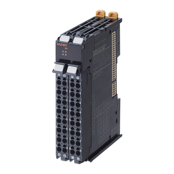
Page 64: Part Names
3 Part Names and Functions Part Names This section describes the names and functions of the parts of the High-speed Analog Input Units. Letter Name Description Marker attachment loca- The locations where markers are attached. The markers made by OM- tions RON are installed for the factory setting. -
Page 65: Indicators
3 Part Names and Functions Indicators The High-speed Analog Input Units have indicators that show the current operating status of the Unit. This section describes the names and functions of the indicators. The appearance of the indicators has been changed for models released in or before March 2019 with lot numbers that represent the date of or after March 20, 2019. -
Page 66: In Indicator
3 Part Names and Functions Color Status Description • Green The Unit is operating normally. • The Unit is ready for I/O refreshing. • I/O checking is operating. • Flashing (at 2-s in- Initializing • tervals) Restarting is in progress for the Unit. •... -
Page 67: Appearance Change Of The Indicators
3 Part Names and Functions 3-2-3 Appearance Change of the Indicators The appearance of the indicators has been changed for models released in or before March 2019 with lot numbers that represent the date of or after March 20, 2019. See below for details on the applicable models and the changes. -
Page 68: Terminal Blocks
3 Part Names and Functions Terminal Blocks Screwless clamping terminal blocks are used for the High-speed Analog Input Units for easy wiring and removal. The compatible terminal blocks for the High-speed Analog Input Units are NX-TBA162 and NX- TBB162. The NX-TBA162 terminal block is connected to the left side of the Unit and the NX-TBA162 terminal block is connected to the right side of the Unit. -
Page 69: Installation And Wiring
Installation and Wiring This section describes how to install the NX Units, the types of power supplies used in the CPU Rack or Slave Terminal, their wiring methods, and how to wire the NX Units. Installing NX Units..................4 - 2 4-1-1 Restriction on Installation Orientation ............ -
Page 70: Installing Nx Units
4 Installation and Wiring Installing NX Units Refer to Installation in the hardware user’s manual for the connected CPU Unit or the user’s manual for the connected Communications Coupler Unit for information on installing NX Units, including the High-speed Analog Input Units. This section describes the restrictions on installation which are specific to the High-speed Analog Input Units. -
Page 71: Restriction On Adjacent Units
4 Installation and Wiring 4-1-2 Restriction on Adjacent Units The following Unit cannot be connected next to a High-speed Analog Input Unit. • Relay Output Unit (NX-OC££££) NX-series NX-series NX-series Relay Output High-speed Relay Output Unit Analog Input Unit (NX-OC Unit (NX-OC (NX-HAD... -
Page 72: Power Supply Types And Wiring
4 Installation and Wiring Power Supply Types and Wiring This section describes the power supply types and wiring. 4-2-1 Power Supply Types There are the following two types of power supplies that supply power to the NX Units. Power supply name Description NX Unit power supply This power supply is used for operating the NX Units. -
Page 73: Calculating The Total Current Consumption From I/O Power Supply
Refer to NX-series System Units User’s Manual (Cat. No. W523) for the specifications of these Units. For a complete list of the latest power supply Units in the NX Series, refer to the product catalog or OMRON website, or contact your OMRON representative. 4-2-3 Calculating the Total Current Consumption from I/O Power Sup-... - Page 74 4 Installation and Wiring bus, the current consumption of each applicable I/O circuit, and current consumption of any connected external devices. • Total Current Consumption from I/O Power Supply of the High-speed Analog Input Unit = (Current consumption from I/O power supply of the High-speed Analog Input Unit) + (Input current to the trigger input terminals ×...
-
Page 75: Wiring The Terminals
4 Installation and Wiring Wiring the Terminals This section describes how to wire the terminals on the High-speed Analog Input Units. WARNING Make sure that the voltages and currents that are input to the Units and slaves are within the specified ranges. Inputting voltages or currents that are outside of the specified ranges may cause accidents or fire. - Page 76 4 Installation and Wiring 1.6 mm max. (except ground terminals) 2.0 mm max. (ground terminals) 2.4 mm max. (except ground terminals) 2.7 mm max. (ground terminals) Using Ferrules If you use ferrules, attach the twisted wires to them. Observe the application instructions for your ferrules for the wire stripping length when attaching ferrules.
- Page 77 4 Installation and Wiring When you use any ferrules other than those in the above table, crimp them to the twisted wires so that the following processed dimensions are achieved. 8 to 10 mm 1.6 mm max. (except ground terminals) 2.0 mm max.
- Page 78 4 Installation and Wiring Precautions for Correct Use • Use cables with suitable wire sizes for the carrying current. There are also restrictions on the current due to the ambient temperature. Refer to the manuals for the cables and use the ca- bles correctly for the operating environment.
- Page 79 4 Installation and Wiring Model Manufacturer SZF 0-0,4X2,5 Phoenix Contact Connecting Ferrules Insert the ferrule straight into the terminal hole. You do not need to insert a flat-blade screwdriver into the release hole. Ferrule After you make a connection, make sure that the ferrule is securely connected to the terminal block.
- Page 80 4 Installation and Wiring Remove the flat-blade screwdriver from the release hole. After you make a connection, lightly pull the twisted wire or the solid wire to make sure that the wire is securely connected to the terminal block. Precautions for Safe Use •...
- Page 81 4 Installation and Wiring Terminals Wire type Twisted wires Solid wires Classifica- Current ca- Ferrule tion pacity Plated Unplated Plated Unplated All terminals 2 A max. except Greater than Not possible Not possible ground termi- 2 A and 4 A nals or less Greater than...
- Page 82 4 Installation and Wiring Secure wires within the range of 30 mm from the screwless clamping terminal block. 30 mm Removing Wires Use the following procedure to remove the wires from the terminal block. The removal method is the same for ferrules, twisted wires, and solid wires. If wires are secured firmly to the terminal block, release them first.
- Page 83 4 Installation and Wiring Insert the flat-blade screwdriver into the release hole and remove the wire from the terminal hole. Wire Remove the flat-blade screwdriver from the release hole. Precautions for Safe Use • Do not press the flat-blade screwdriver straight into the release holes on a screwless clamp- ing terminal block.
- Page 84 4 Installation and Wiring Removing a Terminal Block Press the lock lever on the terminal block and pull out the top of the terminal block to remove it. Lock lever Terminal block Attaching a Terminal Block Mount the terminal block hook that is applicable to each Unit model on the guide at the bottom of the NX Unit, lift up the terminal block, and press in on the top of the terminal block until you hear it engage.
-
Page 85: Preventing Incorrect Attachment Of Terminal Blocks
4 Installation and Wiring 4-3-2 Preventing Incorrect Attachment of Terminal Blocks In order to prevent unintentionally installing the wrong terminal block, you can limit the combination of a Unit and a terminal block. Insert three Coding Pins (NX-AUX02) into three of the six incorrect attachment prevention holes on the Unit and on the terminal block. - Page 86 4 Installation and Wiring Insertion Locations and Patterns of Coding Pins Insert three Coding Pins each on the terminal block and on the Unit at the positions designated by the numbers 1 through 6 in the figure below. As shown in the following table, there are 20 unique pin patterns that you can use. 4 - 18 NX-series Analog I/O Units User’s Manual for High-speed Analog Input Units (W592)
- Page 87 4 Installation and Wiring Terminal block Unit Holes used by Holes used by OMRON OMRON Holes for incorrect Holes for incorrect attachment prevention attachment prevention (pin locations) (pin locations) ○: Pin inserted Pin locations for Pin locations for Unit terminal block Pattern No.1...
- Page 88 • The holes not designated by the numbers 1 through 6 in the above figure are used by OM- RON. If you insert any Coding Pins into the holes reserved for use by OMRON, you will not be able to mount the terminal block to the Unit.
-
Page 89: Checking The Wiring
4 Installation and Wiring Unit 4-3-3 Checking the Wiring Check the wiring by reading input data or writing output data from Slave Terminals using the Watch Tab Page of the Support Software. For Input Units, you can input the signals from external devices that are connected to the target Units and monitor the results. -
Page 90: Wiring External Devices
4 Installation and Wiring Wiring External Devices This section provides information on wiring the High-speed Analog Input Units to external devices. 4-4-1 Terminal Block Arrangement The terminal block arrangement of the High-speed Analog Input Units is shown below. B1C1 Input1+ SHT1+ Input1- IOV1... - Page 91 4 Installation and Wiring Wiring Examples for the NX-HAD401 Wiring Example 1 (Analog input range: Voltage) Use a two-conductor shielded Additional I/O High-speed Analog Input Unit twisted-pair cable. Do not ground Power Supply NX-HAD401 the shield. Unit *1 B1 C1 Output device SHT1+ Input1+...
- Page 92 4 Installation and Wiring I/O Power Supply Unit is also unnecessary if you do not use the trigger inputs of the High-speed Analog Input Units. *2. Short-circuit cables are not included in the product. Precautions for Correct Use The cable length of a short-circuit cable used for current input must be 4 cm or less and allow for wiring to the screwless clamping terminal block.
-
Page 93: Precautions For Wiring
4 Installation and Wiring Wiring Example 2 (Analog input range: Current) Use a two-conductor shielded Additional I/O High-speed Analog Input Unit twisted-pair cable. Do not ground Power Supply NX-HAD402 the shield. Unit *1 B1 C1 Output device SHT1+ Input1+ Input+ Input- IOV1... - Page 94 4 Installation and Wiring However, do not connect the end of the shield anywhere on the output device. If you ground the shield on both the High-speed Analog Input Unit side and the output device side, the Unit becomes suscepti- ble to noise induced due to ground loops.
- Page 95 4 Installation and Wiring Precautions When Connecting a Two-wire DC Sensor When a two-wire sensor is used with the trigger inputs of the High-speed Analog Input Units, check that the following conditions are met. Failure to meet these conditions may result in operating errors. ...
- Page 96 4 Installation and Wiring Relation between Input Current at Trigger Input Terminals and Sensor Control Output (Load Current) The trigger inputs of the High-speed Analog Input Units can detect sensor output ON only when the following conditions are satisfied: (min) ≤...
- Page 97 4 Installation and Wiring Unit that can supply I/O power to the NX bus Two-wire sensor High-speed Analog Input Unit : Power supply voltage : Sensor's output residual voltage : Sensor control output (load current) : Input current at trigger input terminal of the High-speed Analog Input Unit (Input current when the rated voltage is applied) R: Bleeder resistor ...
- Page 98 4 Installation and Wiring Unit that can supply I/O power to the NX bus Two-wire sensor leak High-speed Analog Input Unit The voltages and currents related to the conditions for PNP type sensors are shown in the figure below. Unit that can supply I/O power to the NX bus Two-wire sensor High-speed Analog Input Unit...
- Page 99 4 Installation and Wiring A 100-ms timer delay (the time required for an OMRON Proximity Sensor to stabilize) is created in the user program. After the timer changes to TRUE, input bit X causes the output Output to change to TRUE after the input of the sensor changes to TRUE.
- Page 100 4 Installation and Wiring 4 - 32 NX-series Analog I/O Units User’s Manual for High-speed Analog Input Units (W592)
-
Page 101: I/O Refreshing
I/O Refreshing This section describes the types and functions of I/O refreshing for the NX Units. I/O Refreshing....................5 - 2 5-1-1 I/O Refreshing from CPU Units to NX Units ..........5 - 2 5-1-2 I/O Refreshing from CPU Units or Industrial PCs to Slave Terminal .... 5 - 3 5-1-3 Calculating the I/O Response Time of NX Units ........... -
Page 102: I/O Refreshing From Cpu Units To Nx Units
5 I/O Refreshing I/O Refreshing This section describes I/O refreshing for NX Units. 5-1-1 I/O Refreshing from CPU Units to NX Units An NX-series CPU Unit cyclically performs I/O refreshing with the NX Units. The following period and two cycles affect operation of the I/O refreshing between the CPU Unit and the NX Units. -
Page 103: I/O Refreshing From Cpu Units Or Industrial Pcs To Slave Terminal
5 I/O Refreshing 5-1-2 I/O Refreshing from CPU Units or Industrial PCs to Slave Termi- The CPU Unit or the Industrial PC cyclically performs I/O refreshing with the Slave Terminal through the Communications Master Unit and the Communications Coupler Unit. The following four cycles affect operation of the I/O refreshing between the NX Unit on a Slave Termi- nal and the CPU Unit or Industrial PC. -
Page 104: Calculating The I/O Response Time Of Nx Units
5 I/O Refreshing Operation of I/O Refreshing with NX-series CPU Units The following shows the operation of I/O refreshing when the built-in EtherCAT port on the NX-series CPU Unit is used for communications with an EtherCAT Slave Terminal. • The process data communications cycle in item (b) and the refresh cycle of the NX bus in item (c) are automatically synchronized with the primary period or the task period of the priority-5 periodic task of the CPU Unit in item (a). - Page 105 5 I/O Refreshing Manual for reference Description NX-series Data Reference Manual The NX Unit parameter values used for calculating the I/O re- sponse times of NX Units are described. 5 - 5 NX-series Analog I/O Units User’s Manual for High-speed Analog Input Units (W592)
-
Page 106: I/O Refreshing Methods
5 I/O Refreshing I/O Refreshing Methods This section describes I/O refreshing methods for the NX Units. 5-2-1 Types of I/O Refreshing Methods The I/O refreshing methods that you can use between the CPU Unit or Communications Coupler Unit and the NX Units are determined by the CPU Unit or Communications Coupler Unit that is used. For the High-speed Analog Input Units, synchronous I/O refreshing as described below is always used. -
Page 107: Setting The I/O Refreshing Methods
5 I/O Refreshing 5-2-2 Setting the I/O Refreshing Methods Setting Methods between the CPU Unit and the NX Units How to set an I/O refreshing method between the CPU Unit and the NX Units is determined by the connected CPU Unit. Refer to the software user’s manual for the connected CPU Unit for information on how to set an I/O refreshing method between the CPU Unit and the NX Units. -
Page 108: Restrictions In Refresh Cycles
5 I/O Refreshing NX Units that sup- NX Units that NX Units port Free-Run re- NX Units that DC enable set- NX Units that support both that support freshing, synchro- support only ting in the support only Free-Run re- only Free- nous I/O refresh- time stamp re- EtherCAT Cou-... -
Page 109: I/O Refreshing Operation
5 I/O Refreshing Precautions for Correct Use If you use synchronous I/O refreshing, set the task period of the periodic task as follows. • A value within the specified refresh cycle range of the High-speed Analog Input Unit • A value larger than the NX bus refresh cycle that is automatically calculated by the Support Software Also refer to the user's manual for the connected CPU Unit or EtherCAT Coupler Unit for infor- mation on setting the task periods of periodic tasks. - Page 110 5 I/O Refreshing (e) Interval of I/O refreshing is (d) The CPU Unit reads the data that is read by not constant the Unit at I/O refreshing. The Sysmac Studio (f) Interval of I/O refreshing is constant. automatically calculates the offset between the Not constant synchronization timing and the...
- Page 111 5 I/O Refreshing • The High-speed Analog Input Units perform conversions in order to obtain the input values of the final analog input data sampled, before the timing to read inputs. The timing of starting the AD conversion in the first sampling is the same for all channels of the High-speed Analog Input Unit.
- Page 112 5 I/O Refreshing (d) The Communications Coupler Unit (e) Interval of I/O refreshing is reads the data that is read by the Unit not constant at I/O refreshing. (f) Interval of Sync0 is constant. The Sysmac Studio Not constant automatically calculates Sync0 Sync0 Sync0...
-
Page 113: Input Range And Converted Values
Input Range and Converted Val- This section describes the input range of the High-speed Analog Input Units and the converted values. Voltage Input Range and Converted Values ..........6 - 2 Current Input Range and Converted Values ..........6 - 5 6 - 1 NX-series Analog I/O Units User’s Manual for High-speed Analog Input Units (W592) -
Page 114: Voltage Input Range And Converted Values
6 Input Range and Converted Values Voltage Input Range and Converted Values Analog voltage input signals are converted to digital values according to the input range shown below. If the input range exceeds the value range for which conversion is possible, the converted value is fixed at the upper or lower limit. - Page 115 6 Input Range and Converted Values Converted value (decimal) +32640 +32000 -5.1 V -5 V Voltage +5 V+5.1 V Fixed at the lower limit in case of -5.1 V -32000 Fixed at the upper or less. -32640 limit in case of +5.1 V or more.
- Page 116 6 Input Range and Converted Values Converted value (decimal) +32640 +32000 Fixed at the Fixed at the upper lower limit in limit in case of case of -0.1 V +5.1 V or more. or less. Voltage -640 +5 V +5.1 V -0.1 V Input Range: 1 to 5 V A voltage of 1 to 5 V is converted to a signed integer value (0 to 32000).
-
Page 117: Current Input Range And Converted Values
6 Input Range and Converted Values Current Input Range and Converted Values Analog current input signals are converted to digital values according to the input range shown below. If the input range exceeds the value range for which conversion is possible, the converted value is fixed at the upper or lower limit. - Page 118 6 Input Range and Converted Values Converted value (decimal) +32640 +32000 Fixed at the lower limit Fixed at the upper limit in this range. in case of +20.32 mA or more. Disconnection detected below 1.2 mA. Current +20 mA -640 +20.32 mA +4 mA +1.2 mA...
- Page 119 I/O Data and List of Settings This section describes the I/O data and provides a list of settings for the High-speed Analog Input Units. Specifications of I/O Data ................7 - 2 7-1-1 Allocatable I/O Data..................7 - 2 7-1-2 Data Details ....................
-
Page 120: Specifications Of I/O Data
7 I/O Data and List of Settings Specifications of I/O Data This section describes the I/O data for the High-speed Analog Input Units and provides precautions for the I/O data size. 7-1-1 Allocatable I/O Data Eight I/O entry mappings are assigned to the I/O allocation settings for the High-speed Analog Input Units. - Page 121 7 I/O Data and List of Settings Allocatable I/O Data This section describes I/O data that can be allocated. I/O entry that Regis- changes I/O entry tered by Size accord- Area mapping Data name Data type Reference default (Byte) ing to name Unit op- eration...
- Page 122 7 I/O Data and List of Settings I/O entry that Regis- changes I/O entry tered by Size accord- Area mapping Data name Data type Reference default (Byte) ing to name Unit op- eration settings Input Input Data Ch3 Status WORD £...
- Page 123 7 I/O Data and List of Settings Example of I/O Entry Allocation The allocation of an I/O entry changes according to the Ch£ Enable/Disable and Ch£ Number of Samplings Setting that you set in the Unit operation settings. The following table shows an example of I/O entry allocation that matches the set values of the Unit operation settings.
-
Page 124: Data Details
7 I/O Data and List of Settings I/O entry to be allocated • Ch£ Enable/ • Ch£ Enable/ Disable • Ch£ Enable/ Disable Ch1: Enable Disable All chan- Other chan- All chan- nels: Enable nels: Disable nels: Enable I/O entry mapping •... - Page 125 7 I/O Data and List of Settings Analog Input Time Stamp This indicates the DC time at which AD conversion starts in the first sampling of analog input data dur- ing each task period. The timing of starting the AD conversion is the same for all the channels. Default val- Index num- Subindex...
- Page 126 7 I/O Data and List of Settings Subindex number Data name Data type Default value I/O port name Unit Index number (hex) (hex) Ch3 Status WORD 0000 hex Ch3 Status 6003 Ch4 Status WORD 0000 hex Ch4 Status 6004 The bit configuration and the description of each bit for the Ch£ Status are given in the following ta- ble.
- Page 127 7 I/O Data and List of Settings Byte Bit 7 Bit 6 Bit 5 Bit 4 Bit 3 Bit 2 Bit 1 Bit 0 Ch£ Trigger Input Time Stamp, 1st byte Ch£ Trigger Input Time Stamp, 2nd byte Ch£ Trigger Input Time Stamp, 3rd byte Ch£...
- Page 128 7 I/O Data and List of Settings Index Subindex Default Data name Data type I/O port name Unit number number value (hex) (hex) Ch1 Analog Input Value ARRAY[0..9] OF INT 0 Ch1 Analog Input 6001 991-1000 Value 991-1000 Ch2 Analog Input Value ARRAY[0..9] OF INT 0 Ch2 Analog Input 6002...
- Page 129 7 I/O Data and List of Settings Byte Bit 7 Bit 6 Bit 5 Bit 4 Bit 3 Bit 2 Bit 1 Bit 0 1st byte of Analog Input Value 20 in Ch£ Analog Input Value 11-20 2nd byte of Analog Input Value 20 in Ch£ Analog Input Value 11-20 The bit configuration of the Ch£...
-
Page 130: Precautions For The I/O Data Size
7 I/O Data and List of Settings Data Data name I/O port name Description type Ch£ Moving 1: Disables the moving average filter 1. BOOL Ch£ Moving Average Filter 1 0: Enables the moving average filter 1. Average Filter 1 Disable Disable If the Filter 1 Moving Average Count is set to 0 in the... - Page 131 7 I/O Data and List of Settings Item Description Size of I/O data that can be The size of I/O data that can be allocated to a single High-speed Analog Input allocated to a High-speed Unit is restricted as below. •...
-
Page 132: Setting I/O Allocations With The Sysmac Studio
7 I/O Data and List of Settings Setting I/O Allocations with the Sys- mac Studio Configure the I/O allocation settings of the High-speed Analog Input Unit from the Sysmac Studio. This section describes how to display the Edit I/O Allocation Settings Window, information to be dis- played, and how to configure the I/O allocation settings. - Page 133 7 I/O Data and List of Settings Slave Terminal This section describes how to display the Edit I/O Allocation Settings Window for a High-speed Analog Input Unit connected to a Communications Coupler Unit. In the Multiview Explorer, double-click the Communications Coupler Unit to which the target High-speed Analog Input Unit is connected to open the Edit Slave Terminal Configuration Tab Page.
-
Page 134: Displayed I/O Allocation Settings
7 I/O Data and List of Settings The Edit I/O Allocation Settings Window is displayed. 7-2-2 Displayed I/O Allocation Settings The following I/O allocation settings are displayed. Letter Name/Label Description I/O allocation status For connection to the CPU Unit, the allocated I/O data size is dis- played. - Page 135 7 I/O Data and List of Settings Letter Name/Label Description Task period of assigned periodic The task period of assigned periodic task in the task settings is dis- tasks played. Unit operation In the Unit operation settings, the settings and set values that affect settings the I/O allocations are displayed.
-
Page 136: Configuring The I/O Allocation Settings
7 I/O Data and List of Settings The calculation formula for the sampling frequency is as follows: • Sampling frequency [kHz] = (1 ÷ Sampling period [µs]) × 1,000 7-2-3 Configuring the I/O Allocation Settings The method for configuring the I/O allocation settings is given below. Display the Edit I/O Allocation Settings Window. - Page 137 7 I/O Data and List of Settings Click this button to enable the settings in the Edit I/O Allocation Settings Window, and return to the CPU and Expansion Racks Tab Page or Edit Slave Terminal Configuration Tab Page. 7 - 19 NX-series Analog I/O Units User’s Manual for High-speed Analog Input Units (W592)
-
Page 138: List Of Settings
7 I/O Data and List of Settings List of Settings The followings are the setting descriptions, setting ranges, and default values of the functions that can be used in the High-speed Analog Input Units. Restart the NX Unit if you change any parameter whose update timing comes after a restart of the Unit. - Page 139 7 I/O Data and List of Settings Subin- Index Setting fault Setting Update Refer- Description Unit number name val- range number timing ence (hex) (hex) Ch1 Discon- Set to enable or disable the FALS TRUE or 5004 Immedi- 8-6 Input nection De- disconnection detection.
- Page 140 7 I/O Data and List of Settings Subin- Index Setting fault Setting Update Refer- Description Unit number name val- range number timing ence (hex) (hex) Ch1 Filter 1 Set the moving average 0 to 4096 times 5007 Immedi- 8-5 Digi- Moving Aver- count for the moving aver- ately...
- Page 141 7 I/O Data and List of Settings Set value Meaning 1 time 2 times 4 times 5 times 8 times 10 times 20 times 25 times 40 times 50 times 80 times 100 times 125 times 200 times 250 times 400 times 500 times 625 times...
- Page 142 7 I/O Data and List of Settings 7 - 24 NX-series Analog I/O Units User’s Manual for High-speed Analog Input Units (W592)
-
Page 143: Functions
Functions This section describes the functions of the High-speed Analog Input Units. Function Block Diagram ................8 - 3 Selecting Channel To Use ................8 - 4 8-2-1 Function Applications and Overview............. 8 - 4 8-2-2 Details on the Function ................. 8 - 4 8-2-3 Setting Method.................... - Page 144 8 Functions 8-10 Trigger Input ....................8 - 40 8-10-1 Function Applications and Overview............8 - 40 8-10-2 Details on the Function ................8 - 40 8-10-3 Identifying the Analog Input Value When Trigger Input Was Turned ON ..8 - 45 8-10-4 Setting Method....................
-
Page 145: Function Block Diagram
8 Functions Function Block Diagram This section describes the processing order of analog input signals on the High-speed Analog Input Units. Analog input signals are processed in the following order according to the input range and the number of samplings that you set in the Unit operation settings. Analog input signal Disable Channel... -
Page 146: Selecting Channel To Use
8 Functions Selecting Channel To Use 8-2-1 Function Applications and Overview This function skips the conversion processing and error detection processing for unused inputs, and reduces the size of I/O data for the Unit. 8-2-2 Details on the Function By default, the High-speed Analog Input Units convert as many input signals as the number of inputs on them to obtain analog input data. -
Page 147: Setting Method
8 Functions Connection made to Screen Communication Coupler Unit Edit Slave Terminal Configuration Tab Page After completion of the settings, check with the Support Software that the following conditions are met: • The limitations on the I/O data size are not exceeded. •... -
Page 148: Input Range Selection
8 Functions Input Range Selection 8-3-1 Function Applications and Overview This function sets the input range of analog input. 8-3-2 Details on the Function You can set the input range according to the characteristics of the output device. Set the input range in the Unit operation settings. The settings are shown in the following table. Default Setting name Setting description... - Page 149 8 Functions The settings are reflected after the Unit is restarted. Precautions for Safe Use If you transfer parameters for Unit operation settings that are updated when the Unit is restarted after the settings are changed on the Support Software, the Unit will be restarted after the trans- fer is completed.
-
Page 150: Number Of Samplings Setting
8 Functions Number of Samplings Setting 8-4-1 Function Applications and Overview This function sets the number of samplings of analog input data to obtain. The sampling period is determined by the task period of the assigned periodic task and the number of samplings per period. - Page 151 8 Functions Default Setting Setting name Setting description Unit Update timing value range Ch1 Number of Set the number of samplings per task times After the Unit is re- Samplings Setting period for analog input data. started Ch2 Number of Samplings Setting Ch3 Number of Samplings Setting...
- Page 152 8 Functions Connection made to Screen Communication Coupler Unit Edit Slave Terminal Configuration Tab Page After completion of the settings, check with the Support Software that the following conditions are met: • The limitations on the I/O data size are not exceeded. •...
-
Page 153: Setting Method
8 Functions Sampling period [µs] Number of Task peri- Task peri- Task peri- Task peri- samplings Task period Task peri- Task peri- od 1000 od 2000 od 4000 od 8000 [times] od 250 µs od 500 µs 125 µs µs µs µs µs... - Page 154 8 Functions This section describes how to display the Sampling Settings and Digital Filter Settings Tab Page and information to be displayed. Display Method Connected to a CPU Unit This section describes how to display the Sampling Settings and Digital Filter Settings Tab Page for a High-speed Analog Input Unit connected to a CPU Unit.
- Page 155 8 Functions Slave Terminal This section describes how to display the Sampling Settings and Digital Filter Settings Tab Page for a High-speed Analog Input Unit connected to a Communications Coupler Unit. In the Multiview Explorer, double-click the Communications Coupler Unit to which the target High-speed Analog Input Unit is connected to open the Edit Slave Terminal Configuration Tab Page.
- Page 156 8 Functions The Sampling Settings and Digital Filter Settings Tab Page is displayed. Displayed Information The following information is displayed on the Sampling Settings and Digital Filter Settings Tab Page. 8 - 14 NX-series Analog I/O Units User’s Manual for High-speed Analog Input Units (W592)
- Page 157 8 Functions Let- Name/Label Description Task period of assigned periodic task The task period of assigned periodic task in the task settings is displayed. Enable/Disable set- Enable/Disa- Values that you set for Ch£ Enable/Disable in the Unit opera- tings of Ch tion settings are displayed.
- Page 158 8 Functions Let- Name/Label Description Digital fil- Digital Setting value Values that you set for Ch£ Digital Low-pass Filter Cutoff ter set- low-pass of cutoff fre- Frequency in the Unit operation settings are displayed. tings filter quency [×10 For disabled channels, or channels whose sampling period is less than 5 µs, - is displayed in the Ch column.
- Page 159 8 Functions Refer to Digital Filter Processing Period on page 8 - 19 for calculation formulas for the Digital Filter Proc- essing Period and Digital Filter Processing Frequency. 8 - 17 NX-series Analog I/O Units User’s Manual for High-speed Analog Input Units (W592)
-
Page 160: Digital Filtering
8 Functions Digital Filtering 8-5-1 Function Applications and Overview This function uses the digital filter to remove noise components that are contained in analog input sig- nals to suppress the fluctuations of analog input values. A digital filter can remove electrical noise that is contained in analog input signals to provide stable measurements. - Page 161 8 Functions Digital Filter Processing Period The following describes the Digital Filter Processing Period, which is the data processing period for the digital low-pass filter and moving average filters. Application The Digital Filter Processing Period is used to calculate the set value of the digital low-pass filter cutoff frequency, the set value of the moving average count for a moving average filter, and the de- lay time.
- Page 162 8 Functions Additional Information The digital filter processing frequency can be calculated as follows: • Ch£ Digital Filter Processing Frequency [kHz] = (1 ÷ Ch£ Digital Filter Processing Period [µs]) × 1,000 How to Check the Processing Period You can check the Digital Filter Processing Period value on the Sampling Settings and Digital Filter Settings Tab Page of the Support Software.
- Page 163 8 Functions Setting descrip- Setting Update Setting name fault Unit Remarks tion range timing value Ch1 Digital Low- Set the digital low- 0 to × 10 Immedi- Set this parameter to 0 pass Filter Cutoff pass filter cutoff ately to disable the digital 9900 Frequency frequency.
- Page 164 8 Functions To enable/disable the digital low-pass filter with the relevant bit, set the cutoff frequency in the Unit operation settings to a value other than 0. If the cutoff frequency is set to 0, the digital low-pass filter will not be enabled even if the relevant bit is set to enable. The relevant bit is Ch£...
- Page 165 8 Functions Step signal fc = 1 kHz Step response time 1000 1500 Time [µs] The step response times for typical cutoff frequencies are shown below. Cutoff frequency [Hz] Step response time [µs] 36,646.8 3,664.7 366.4 10 k 36.2 50 k The smaller the cutoff frequency is, the wider range of noise you can remove.
- Page 166 8 Functions The High-speed Analog Input Units convert input signals based on the Digital Filter Processing Pe- riod. Converted analog input data is stored in moving average buffers to perform the moving aver- age processing. If the moving average count is not reached, the analog input data stored in the buf- fers is processed as moving average data.
- Page 167 8 Functions Setting Update Setting name Setting description fault Unit Remarks range timing value Ch1 Filter 1 Set the moving aver- 0 to 4096 times Immedi- Set this parameter to 0 to Moving Aver- age count for the mov- ately disable the moving aver- age Count ing average filter 1.
- Page 168 8 Functions Attenuation Characteristics and Step Response Characteristics (a) Attenuation characteristics You can use the moving average filter to significantly attenuate the signals in the specific fre- quency and the frequencies that are integer multiples of that frequency. The following calculation formula shows the relationship between the frequency f and the set value of the moving average count.
-
Page 169: Setting Method
8 Functions Processing Period is 5 µs. The delay time of the moving average filter when the moving aver- age count is set to 200 times is 995 µs. The delay time is the time until the output of the mov- ing average filter reaches 100% from 0% when the step signal is input for one moving average filter. -
Page 170: Checking The Digital Filter Settings
8 Functions The settings are transferred from the Sysmac Studio to the NX Unit. The settings are reflected immediately. 8-5-4 Checking the Digital Filter Settings You can check the digital filter settings on the Sampling Settings and Digital Filter Settings Tab Page of the Support Software. -
Page 171: Input Disconnection Detection
8 Functions Input Disconnection Detection 8-6-1 Function Applications and Overview This function detects disconnections of the analog input signal lines. However, it detects disconnections only when the input range is 1 to 5 V or 4 to 20 mA. 8-6-2 Details on the Function •... -
Page 172: Setting Method
8 Functions 8-6-3 Setting Method This section describes how to configure settings with the Sysmac Studio. Display the Edit Unit Operation Settings Tab Page. For how to display the tab page, refer to A-8 Displaying the Edit Unit Operation Settings Tab Page on page A - 54. -
Page 173: Over Range/Under Range Detection
8 Functions Over Range/Under Range Detection 8-7-1 Function Applications and Overview This function detects when the analog input signal exceeds the range for which conversion is possible. 8-7-2 Details on the Function The operations of the over range/under range detection are described below. •... -
Page 174: Setting Method
8 Functions 8-7-3 Setting Method No setting is required. 8 - 32 NX-series Analog I/O Units User’s Manual for High-speed Analog Input Units (W592) -
Page 175: User Calibration
8 Functions User Calibration 8-8-1 Function Applications and Overview This function corrects offsets in the converted values that occur due to the deterioration of the High- speed Analog Input Units, and calibrates the Units again. You can use this function to calibrate the equipment that requires the periodic calibration. 8-8-2 Details on the Function This function corrects the converted values of input voltages and input currents at 2 points, 0% and... -
Page 176: Setting Method
8 Functions The correctable range for each input range is as follows. Correctable range Input range 100% -10 to 10 V -10.2 to -9.8 V 9.8 to 10.2 V -5 to 5 V -5.1 to -4.9 V 4.9 to 5.1 V 0 to 10 V -0.2 to 0.2 V 9.8 to 10.2 V... - Page 177 8 Functions An execution confirmation dialog box is displayed. Click the Yes Button. When the writing is completed successfully, the following dialog box is displayed. Click the OK Button. Enter the voltage or current corresponding to lower limit (0%) to the Unit terminal, then click the Write Button under Lower limit settings.
- Page 178 8 Functions An execution confirmation dialog box is displayed. Click the Yes Button. When the writing is completed successfully, the following dialog box is displayed. Click the OK Button. Additional Information • A new calibration value is reflected immediately after you write it. •...
- Page 179 8 Functions Display the User Calibration Window. For the display methods, refer to A-10 Displaying the User Calibration Window on page A - 59. Click the Clear All Button under All Channel Settings. An execution confirmation dialog box is displayed. Click the Yes Button.
-
Page 180: Zero Set/Reset
8 Functions Zero Set/Reset 8-9-1 Function Applications and Overview The zero set function corrects the analog input value to be the zero point at a desired time. The zero reset function resets the correction that is performed with the zero set function. Use these functions to correct the zero points of analog input signals. -
Page 181: Setting Method
8 Functions Analog input value Original input value Input value after zero set execution Original input value Input value after zero set execution Zero Set Execution bit Zero Set Executing bit 8-9-3 Setting Method No setting is required. 8 - 39 NX-series Analog I/O Units User’s Manual for High-speed Analog Input Units (W592) -
Page 182: 8-10 Trigger Input
8 Functions 8-10 Trigger Input 8-10-1 Function Applications and Overview This function obtains the input value of the digital input signal to trigger analog input signals, and the DC time when the digital input value changes. The function is used to identify the analog input signal that is obtained at the input timing of a digital input signal. - Page 183 8 Functions • The timing of reading input changed times, the synchronization timing, and the maximum NX bus I/O refresh cycle are automatically calculated by the Sysmac Studio according to the input re- fresh cycles of the NX Units on the CPU Unit when the Unit Configuration in the CPU Unit is cre- ated and set up.
- Page 184 8 Functions Synchronization timing Synchronization timing Synchronization timing I/O refreshing of Input refreshing the NX bus Output refreshing DC time Rising edge Input Trigger input to value the High-speed Analog Input Input changed Unit time Records the DC time when the input value changes from OFF to ON.
- Page 185 8 Functions • The High-speed Analog Input Units in the Slave Terminal read input changed times at a fixed in- terval based on Sync0. (Refer to (a) in the figure below.) • The High-speed Analog Input Units read input values at the timing of I/O refreshing, which is dif- ferent from the timing of reading input changed times.
- Page 186 8 Functions (c) Interval of I/O refreshing is not (b) The Communications Coupler constant Unit reads the input changed time that is read by the Unit I/O refresh cycle (d) Interval of Sync0 is and the input value at this The longest AD conversion constant.
-
Page 187: Identifying The Analog Input Value When Trigger Input Was Turned On
8 Functions Sync0 Sync0 Sync0 I/O refreshing of Input refreshing the NX bus Output refreshing DC time Rising edge Input Trigger input to value the High-speed Input Analog Input changed Unit time Records the DC time when the input value changes from OFF to ON. - Page 188 8 Functions • Task period of assigned periodic task: 1 ms • Number of Ch1 samplings: 5 Timing Chart Example The following figure shows the timing chart. 1 ms Ch1: Number of 2 3 4 5 Samplings set Analog input to the to 5 High-speed Analog Analog input...
-
Page 189: Setting Method
8 Functions Ch1 Analog Input Time Stamp Symbol DC time Tana0 0 ms Tana1 1 ms Tana2 2 ms Tana3 3 ms The Analog Input Time Stamp immediately before Ttrg1 is Tana2. The DC time of Tana2 is 2 You can check the Analog Input Time Stamp with the Analog Input Time Stamp of I/O data. Refer to Analog Input Time Stamp on page 7 - 7 for details on I/O data. -
Page 190: 8-11 Input Filter
8 Functions 8-11 Input Filter 8-11-1 Function Applications and Overview This function prevents data changes and unstable data if the input bits of the digital input signal that is used as trigger input are unstable due to chattering or noise. 8-11-2 Details on the Function Read the inputs at a 1/4 interval of the input filter time. -
Page 191: Setting Method
8 Functions Default Update tim- Setting name Setting description Setting range Unit value Ch1 Input Filter Val- Set the filter time for trigger input signals. Immediately 0, or 3 to 9 ue Setting Set one of the following: • No Filter Ch2 Input Filter Val- •... - Page 192 8 Functions The settings are reflected immediately. 8 - 50 NX-series Analog I/O Units User’s Manual for High-speed Analog Input Units (W592)
-
Page 193: Troubleshooting
Troubleshooting This section describes the error information and corrections for errors that can occur when the High-speed Analog Input Units are used. How to Check for Errors ................9 - 2 Checking for Errors with the Indicators............. 9 - 3 Checking for Errors and Troubleshooting on the Support Software .. -
Page 194: How To Check For Errors
9 Troubleshooting How to Check for Errors Use one of the following error checking methods. • Checking the indicators • Troubleshooting with the Support Software Refer to the user's manual for the CPU Unit or Communications Coupler Unit that the NX Units are connected to for information on checking errors with the troubleshooting functions of the Support Soft- ware. -
Page 195: Checking For Errors With The Indicators
9 Troubleshooting Checking for Errors with the Indica- tors You can use the TS indicators on the High-speed Analog Input Units to check the NX Unit status and level of errors. This section describes the meanings of errors that the TS indicator shows and the troubleshooting pro- cedures for them. - Page 196 9 Troubleshooting TS indicator Cause Correction Green Not Lit Control Parameter Error in Mas- Refer to Control Parameter Error in Master ( page 9 - 16). Not Lit NX Unit Processing Error Refer to NX Unit Processing Error ( page 9 - 20).
-
Page 197: Checking For Errors And Troubleshooting On The Support Software
9 Troubleshooting Checking for Errors and Trouble- shooting on the Support Software Error management on the NX Series is based on the methods used for the NJ/NX/NY-series Control- lers. This allows you to use the Support Software to check the meanings of errors and troubleshooting pro- cedures. -
Page 198: Checking For Errors From Support Software Other Than The Sysmac Studio
9 Troubleshooting Refer to the troubleshooting manual for the connected CPU Unit or Industrial PC and the Sysmac Studio Version 1 Operation Manual (Cat. No. W504) for information on the items you can check and for how to check for errors. Refer to 9-3-3 Event Codes and Corrections for Errors on page 9 - 6 for information on event codes. - Page 199 9 Troubleshooting Level Event Event code Meaning Assumed cause Reference name • 10400000 hex Analog Unit An error occurred for The power supply to the Ana- ¡ page Calibration the calibration data 9 - 15 log Unit was turned OFF or Parameter in the Analog Unit.
- Page 200 9 Troubleshooting Level Event Event code Meaning Assumed cause Reference name 30070000 hex I/O Alloca- I/O allocations are For the NX bus of CPU Units ¡ page • tion Setting not set correctly. 9 - 18 I/O Entry that matches the Error following setting items of unit operation settings has not...
- Page 201 9 Troubleshooting Level Event Event code Meaning Assumed cause Reference name • 65060000 hex Unit I/O Dis- A disconnected input Input wiring is broken. ¡ 8 page connection was detected for • 9 - 22 Input wiring is disconnected. Detected for channel 4.
- Page 202 9 Troubleshooting Level Event Event code Meaning Assumed cause Reference name 80210000 hex NX Unit An output synchroni- For the NX bus of CPU Units ¡ page • Output Syn- zation error occurred 9 - 25 I/O refreshing on the NX bus chronization in the NX Unit.
- Page 203 9 Troubleshooting Level Event Event code Meaning Assumed cause Reference name • 64F20000 hex Unit Over The analog input da- The analog input data ex- 8 ¡ page Range for ta for input channel 3 9 - 28 ceeded the upper limit of the Channel 3 exceeded the upper input range.
-
Page 204: Meaning Of Error
9 Troubleshooting Level Event Event code Meaning Assumed cause Reference name • 64FB0000 hex Unit Under The analog input da- The analog input data went 8 ¡ page Range for ta for input channel 4 9 - 32 below the lower limit of the in- Channel 4 went below the lower put range. - Page 205 • Starts: Execution of the user program starts. *5. “System information” indicates internal system information that is used by OMRON. *6. Refer to the appendices of the troubleshooting manual for the connected CPU Unit or Industrial PC for the applicable range of the HMI Troubleshooter.
- Page 206 9 Troubleshooting Error Descriptions This section describes errors that occur in the High-speed Analog Input Units. Event name Non-volatile Memory Hardware Error Event code 00200000 hex Meaning An error occurred in non-volatile memory. Source Depends on where the Support Source details NX Unit Detection tim- When power is Software is connected and the...
- Page 207 9 Troubleshooting Event name Analog Unit Calibration Parameter Error Event code 10400000 hex Meaning An error occurred for the calibration data in the Analog Unit. Source Depends on where the Support Source details NX Unit Detection tim- When power is Software is connected and the turned ON to system configuration.
- Page 208 9 Troubleshooting Event name Control Parameter Error in Master Event code 10410000 hex Meaning An error occurred in the control parameters that are saved in the master. Source Depends on where the Support Source details NX Unit Detection tim- When power is Software is connected and the turned ON to system configuration.
- Page 209 9 Troubleshooting Event name Unit Calibration Value Error Event code 10440000 hex Meaning There is an error in the area in which the Unit calibration values are saved. Source Depends on where the Support Source details NX Unit Detection tim- When power is Software is connected and the turned ON to...
- Page 210 9 Troubleshooting Event name I/O Allocation Setting Error Event code 30070000 hex Meaning I/O allocations are not set correctly. Source Depends on where the Support Source details NX Unit Detection tim- Continuously Software is connected and the system configuration. Error attrib- Level Minor fault Log category...
- Page 211 9 Troubleshooting Event name Number of Samplings Setting Error Event code 38970000 hex Meaning The sampling period is less than the lower limit of the conversion time for the Unit. The number of sam- plings is not set correctly. Source Depends on where the Support Source details NX Unit Detection tim-...
- Page 212 Cycle the power supply to the Unit, restart the NX Unit, or re- start the NX bus. If this error oc- curs again even after the above correction, contact your OMRON representative. For Communications Coupler Units Cycle the power supply to the Unit, restart the NX Unit, or re- start the Slave Terminal.
- Page 213 9 Troubleshooting Event name Unit I/O Disconnection Detected for Channel 1 Event code 65030000 hex Meaning A disconnected input was detected for channel 1. Source Depends on where the Support Source details NX Unit Detection tim- Continuously Software is connected and the system configuration.
- Page 214 9 Troubleshooting Event name Unit I/O Disconnection Detected for Channel 3 Event code 65050000 hex Meaning A disconnected input was detected for channel 3. Source Depends on where the Support Source details NX Unit Detection tim- Continuously Software is connected and the system configuration.
- Page 215 9 Troubleshooting Event name NX Unit I/O Communications Error Event code 80200000 hex Meaning An I/O communications error occurred in an NX Unit. Source Depends on where the Support Source details NX Unit Detection tim- Continuously Software is connected and the system configuration.
- Page 216 9 Troubleshooting Cause and For Communications Coupler Units correction An error that prevents normal NX Check the error that occurred in Take preventive measures bus communications occurred in the Communication Coupler Unit against the error that occurred in a Communications Coupler Unit. and perform the required correc- the Communication Coupler Unit.
- Page 217 9 Troubleshooting Event name NX Unit Output Synchronization Error Event code 80210000 hex Meaning An output synchronization error occurred in the NX Unit. Source Depends on where the Support Source details NX Unit Detection tim- Continuously Software is connected and the system configuration.
- Page 218 9 Troubleshooting Event name NX Unit Clock Not Synchronized Error Event code 80240000 hex Meaning A time information error occurred in an NX Unit. Source Depends on where the Support Source details NX Unit Detection tim- Continuously Software is connected and the system configuration.
- Page 219 9 Troubleshooting Event name Unit Over Range for Channel 1 Event code 64F00000 hex Meaning The analog input data for input channel 1 exceeded the upper limit of the input range. Or, the analog output data for output channel 1 exceeded the upper limit of the output range. Source Depends on where the Support Source details NX Unit...
- Page 220 9 Troubleshooting Event name Unit Over Range for Channel 3 Event code 64F20000 hex Meaning The analog input data for input channel 3 exceeded the upper limit of the input range. Or, the analog output data for output channel 3 exceeded the upper limit of the output range. Source Depends on where the Support Source details NX Unit...
- Page 221 9 Troubleshooting Event name Unit Under Range for Channel 1 Event code 64F80000 hex Meaning The analog input data for input channel 1 went below the lower limit of the input range. Or, the analog output data for output channel 1 went below the lower limit of the output range. Source Depends on where the Support Source details NX Unit...
- Page 222 9 Troubleshooting Event name Unit Under Range for Channel 2 Event code 64F90000 hex Meaning The analog input data for input channel 2 went below the lower limit of the input range. Or, the analog output data for output channel 2 went below the lower limit of the output range. Source Depends on where the Support Source details NX Unit...
- Page 223 9 Troubleshooting Event name Unit Under Range for Channel 3 Event code 64FA0000 hex Meaning The analog input data for input channel 3 went below the lower limit of the input range. Or, the analog output data for output channel 3 went below the lower limit of the output range. Source Depends on where the Support Source details NX Unit...
- Page 224 9 Troubleshooting Event name Unit Under Range for Channel 4 Event code 64FB0000 hex Meaning The analog input data for input channel 4 went below the lower limit of the input range. Or, the analog output data for output channel 4 went below the lower limit of the output range. Source Depends on where the Support Source details NX Unit...
- Page 225 9 Troubleshooting Event name NX Message Communications Error Event code 80220000 hex Meaning An error was detected in message communications and the message frame was discarded. Source Depends on where the Support Source details NX Unit Detection tim- During NX Software is connected and the message com- system configuration.
- Page 226 9 Troubleshooting Event name Event Log Cleared Event code 90400000 hex Meaning The event log was cleared. Source Depends on where the Support Source details NX Unit Detection tim- When com- Software is connected and the manded from system configuration. user Error attrib- Level...
-
Page 227: Resetting Errors
9 Troubleshooting Resetting Errors Refer to the user’s manual for the connected CPU Unit or Communications Coupler Unit for informa- tion on how to reset errors. 9 - 35 NX-series Analog I/O Units User’s Manual for High-speed Analog Input Units (W592) -
Page 228: Unit-Specific Troubleshooting
9 Troubleshooting Unit-specific Troubleshooting The following table shows the errors, their assumed causes, and corrections for the High-speed Ana- log Input Units. Problem Assumed cause Correction The converted values or analog input val- The user calibration error Execute the user calibration again. ues are different from expected or the error is too large. - Page 229 9 Troubleshooting Problem Assumed cause Correction The disconnection indication does not clear. An output device is dis- Restore the output device connec- connected. tion. Check the output device and input type. The input is significantly Check that the input is correct. out of the output device measurement range.
- Page 230 9 Troubleshooting Problem Assumed cause Correction The external device connected to the trig- An NX bus error or a com- When the Unit is connected to the ger input terminal is ON and the IN indica- munications error occur- CPU Unit, check if a NX bus error tor is lit, but nothing is input.
-
Page 231: Analog Input Value When An Error Occurs
9 Troubleshooting Analog Input Value When an Error Occurs If an error is detected in the process of converting analog input data, the analog input is converted as shown in the table below. These converted values can tell you if the following errors have occurred. Error name Data name Analog input value when an error occurs Unit I/O Disconnection Detected for Channel £... -
Page 232: Troubleshooting Flowchart
9 Troubleshooting Troubleshooting Flowchart Refer to the user’s manual for the connected CPU Unit or Communications Coupler Unit for details on the standard troubleshooting process when an error occurs. 9 - 40 NX-series Analog I/O Units User’s Manual for High-speed Analog Input Units (W592) -
Page 233: Inspection And Maintenance
Inspection and Maintenance This section describes how to clean, inspect, and maintain the system. 10-1 Cleaning and Inspection................10 - 2 10-1-1 Cleaning...................... 10 - 2 10-1-2 Periodic Inspections..................10 - 2 10-2 Maintenance Procedures................10 - 5 10 - 1 NX-series Analog I/O Units User’s Manual for High-speed Analog Input Units (W592) -
Page 234: Cleaning And Inspection
10 Inspection and Maintenance 10-1 Cleaning and Inspection This section describes daily maintenance and the cleaning and inspection methods. Inspect the High-speed Analog Input Units daily or periodically in order to keep it in optimal operating condition. 10-1-1 Cleaning Clean the High-speed Analog Input Units regularly as described below in order to keep it in optimal operating condition. - Page 235 10 Inspection and Maintenance Inspec- Inspection details Criteria Correction tion item Ambient Is the ambient operating 0 to 55°C Use a thermometer to check the environ- temperature within stand- temperature and ensure that the ment ards? ambient operating temperature re- mains within the allowed range of 0 to 55°C.
- Page 236 10 Inspection and Maintenance • Voltage tester or digital voltmeter • Industrial alcohol and pure cotton cloth Tools Required Occasionally • Oscilloscope • Thermometer and hygrometer 10 - 4 NX-series Analog I/O Units User’s Manual for High-speed Analog Input Units (W592)
-
Page 237: Maintenance Procedures
10 Inspection and Maintenance 10-2 Maintenance Procedures When you replace a High-speed Analog Input Unit, follow the procedure in the user’s manual for the connected CPU Unit or Communications Coupler Unit. 10 - 5 NX-series Analog I/O Units User’s Manual for High-speed Analog Input Units (W592) - Page 238 10 Inspection and Maintenance 10 - 6 NX-series Analog I/O Units User’s Manual for High-speed Analog Input Units (W592)
-
Page 239: Appendices
Appendices The appendices provide data sheets, dimensions, and other information for the High- speed Analog Input Units. Data Sheet....................A - 2 A-1-1 Model List ..................... A - 2 A-1-2 High-speed Analog Input Units ..............A - 3 Dimensions ....................A - 11 Programming Examples for Analog Input Data Collection with the Library.................... -
Page 240: A-1 Data Sheet
Appendices A-1 Data Sheet This section provides the specifications of the High-speed Analog Input Units. A-1-1 Model List Trigger input sec- Analog input section tion I/O re- Refer- Model freshing Num- Input Num- Internal ence Resolu- Conver- method ber of Input range meth- ber of... -
Page 241: A-1-2 High-Speed Analog Input Units
Appendices A-1-2 High-speed Analog Input Units Description of Items on Data Sheet of the High-speed Analog Input Units The meanings of the items on the data sheet of the High-speed Analog Input Units are explained in the table below. Item Description Unit name The name of the Unit. - Page 242 Appendices Item Description Isolation method The isolation method between the input circuits and internal circuits and be- tween the input circuits of the Unit. Insulation resistance The insulation resistance between the input circuits and internal circuits and between the input circuits of the Unit. Dielectric strength The dielectric strength between the input circuits and internal circuits and be- tween the input circuits of the Unit.
- Page 243 Appendices Details on Data Sheet Unit name High-speed Analog Input Unit Model NX-HAD401 External connection Screwless clamping terminal block (16 terminals ×2) terminals I/O refreshing method Synchronous I/O refreshing Indicators TS indicator, IN indicator Analog Number of 4 points Trigger Number of 4 points input...
- Page 244 Appendices Dimensions 24 (W) × 100 (H) × 71 (D) Isolation method Between the analog input and the NX bus: Power = Transformer, Signal = Digital isolator Between analog inputs: Power = Transformer, Signal = Digital isola- Between the trigger input and the NX bus: Signal = Digital isolator Between the analog input and the trigger input: Power = Transform-...
- Page 245 Appendices Terminal connection Use a two-conductor diagram shielded twisted-pair Additional I/O Power High-speed Analog Input Unit cable. Do not ground Supply Unit *3 NX-HAD401 the shield. B1 C1 Output device SHT1+ Input1+ Input+ Input- IOV1 IOG1 SHT1- Input1- To use current input, SHT2+ Input2+ connect SHT□+ and...
- Page 246 Appendices Unit name High-speed Analog Input Unit Model NX-HAD402 External connection Screwless clamping terminal block (16 terminals ×2) terminals I/O refreshing method Synchronous I/O refreshing Indicators TS indicator, IN indicator Analog Number of 4 points Trigger Number of 4 points input points input...
- Page 247 Appendices Dimensions 24 (W) × 100 (H) × 71 (D) Isolation method Between the analog input and the NX bus: Power = Transformer, Signal = Digital isolator Between analog inputs: Power = Transformer, Signal = Digital isola- Between the trigger input and the NX bus: Signal = Digital isolator Between the analog input and the trigger input: Power = Transform-...
- Page 248 Appendices Installation orienta- Installation orientation: • Connected to a CPU Unit tion and restrictions Possible in upright installation. • Connected to a Communications Coupler Unit Possible in upright installation. Restrictions: No restrictions Terminal connection Use a two-conductor diagram shielded twisted-pair cable.
-
Page 249: A-2 Dimensions
Appendices A-2 Dimensions 24 mm Width 0.55 26.1 24.0 65.2 A - 11 NX-series Analog I/O Units User’s Manual for High-speed Analog Input Units (W592) - Page 250 Appendices Installation Height (Unit: mm) A - 12 NX-series Analog I/O Units User’s Manual for High-speed Analog Input Units (W592)
-
Page 251: Programming Examples For Analog Input Data Collection With The Library
Appendices A-3 Programming Examples for Analog Input Data Collection with the Library The High-speed Analog Input Units read each analog input value that has been sampled in the task periods of the assigned periodic task as more than one I/O data item. DeviceVariableToArray_100 (Join Device Output Data), a library in the High-speed Analog Inspection Library of Sysmac Library, enables you to join more than one I/O data item into one array variable. - Page 252 Appendices Unit Operation Settings The following table shows the Unit operation settings for the High-speed Analog Input Units that you set in the program. Use the default values for settings that are not given in the table. Setting Set value Meaning of setting Ch1 Enable/Disable TRUE...
- Page 253 Appendices I/O port name Variable name Description Data type Variable type Ch1 Analog Input N2_Ch1_Analog_In- Ch1 Analog Input ARRAY[0..9] Global variable Value 91-100 put_Value_91_100 Value OF INT 91-100 Variable Table External variables and internal variables that are used in the programming are given below. ...
- Page 254 Appendices Data Initial Con- Network Variable name Retain Description type value stant publish Ch1_Input_Data Do not Ch1 Input Data RAY[0..9 publish. 9] OF REAL Internal Variables Initial val- Variable name Data type Constant Description tain I_O_Data_is_Valid BOOL FALSE NX Unit I/O Data Com- munications Enabled Ch1_Arrange- BOOL...
-
Page 255: Connection To The Communications Coupler Unit
Appendices //******************************************************** IF NXBus_N2_NX_Unit_I_O_Data_Active_Status=TRUE AND NXBus_N2_NX_Unit_Error_Status=F ALSE THEN I_O_Data_is_Valid:=TRUE; ELSE I_O_Data_is_Valid:=FALSE; END_IF; IF I_O_Data_is_Valid=TRUE THEN \\OmronLib\NX_HAD\DeviceVariableToArray_100( ENO=>Enable_OUT, Input01:=N2_Ch1_Analog_Input_Value_1_10, Input02:=N2_Ch1_Analog_Input_Value_11_20, Input03:=N2_Ch1_Analog_Input_Value_21_30, Input04:=N2_Ch1_Analog_Input_Value_31_40, Input05:=N2_Ch1_Analog_Input_Value_41_50, Input06:=N2_Ch1_Analog_Input_Value_51_60, Input07:=N2_Ch1_Analog_Input_Value_61_70, Input08:=N2_Ch1_Analog_Input_Value_71_80, Input09:=N2_Ch1_Analog_Input_Value_81_90, Input10:=N2_Ch1_Analog_Input_Value_91_100, StartPos:=UINT#0, InputSize:=N2_Ch1_Number_of_Samplings, DataArray:=Ch1_Input_Data); END_IF; IF Enable_OUT=TRUE THEN Ch1_Arrangement_is_Success:=TRUE; END_IF; A-3-3 Connection to the Communications Coupler Unit In the programming example where the High-speed Analog Input Unit is connected to an NX-ECC203 EtherCAT Coupler Unit, only differences from the case where it is connected to a CPU Unit are descri- bed. - Page 256 Appendices Output device Letter Description Model Description NX-series CPU Unit NX102-££££ EtherCAT Coupler Unit NX-ECC203 Node address: 1 • High-speed Analog Input Unit NX-HAD401 NX Unit number: 1 • Channel used: Ch1 Variable Table External variables and internal variables that are used in the programming are given below. ...
- Page 257 Appendices Internal Variables Initial val- Variable name Data type Constant Description tain I_O_Data_is_Valid BOOL FALSE NX Unit I/O Data Com- munications Enabled BOOL FALSE EQ_OUT This variable is used only in ST programming. Ladder Programming Change the program as follows when the Unit is connected to an EtherCAT Coupler Unit. Before change NXBus_N2_ NX_Unit_...
- Page 258 Appendices I_O_Data_is_Valid:=TRUE; ELSE I_O_Data_is_Valid:=FALSE; END_IF; Change the program as follows. After change IF _EC_PDSlavTbl[1]=TRUE AND _EC_CommErrTbl[1]=FALSE AND _EC_SlavErrTbl[1]=WORD#16# 0002 THEN EQ_OUT:=TRUE; ELSE EQ_OUT:=FALSE; END_IF; IF EQ_OUT =TRUE AND _EC_InDataInvalid=FALSE THEN I_O_Data_is_Valid:=TRUE; ELSE I_O_Data_is_Valid:=FALSE; END_IF; A - 20 NX-series Analog I/O Units User’s Manual for High-speed Analog Input Units (W592)
-
Page 259: A-4 Digital Filter Design With The Library
Appendices A-4 Digital Filter Design with the Library This section shows digital filter design examples that utilize the following libraries in the High-speed Analog Inspection Library of Sysmac Library. • DeviceVariableToArray_100 (Join Device Output Data) • DataRecorder (Data Recorder) • LogDataToCSV (Write Log Data to CSV File) These libraries enable you to output the analog input values that have been read by a High-speed An- alog Input Unit to a CSV file. - Page 260 Appendices Functions To Use The following functions are used in the design examples. • High-speed Analog Inspection Library of Sysmac Library DeviceVariableToArray_100 (Join Device Output Data) DataRecorder (Data Recorder) LogDataToCSV (Write Log Data to CSV File) • Moving average filter of digital filtering In this example, the moving average filter is used to attenuate the signals in the specific frequency because the effect of periodic noise is assumed.
- Page 261 Appendices StartDateTime 2018-01-23-18:32:43.853000000 EndDateTime 2018-01-23-18:32:43.972000000 TriggerDateTime 2018-01-23-18:32:43.853000000 Data at start RecordNum 12000 of recording TriggerPos TimeStamp Data 1.07479E+11 9857 1.07479E+11 9823 1.07479E+11 9790 1.07479E+11 9760 1.07479E+11 9725 1.07479E+11 9693 1.07479E+11 9662 1.07479E+11 9630 1.07479E+11 9591 1.07479E+11 9566 • Column A shows the Analog Input Time Stamps. •...
- Page 262 Appendices According to the graph, the number of data items for one fluctuation period is approximately 1,000. When the task period of the assigned periodic task is 1 ms and the number of samplings is 100, the data sampling period is 10 µs. If the fluctuation frequency of the Ch1 Analog Input Value is calculated, it will be as follows.
-
Page 263: A-4-3 Programming Example
Appendices Fluctuations in the measurement values are significantly suppressed by the Ch1 Moving Aver- age Filter 1. Analog input value after moving average filtering 13000 12000 11000 10000 9000 8000 7000 6000 5000 4000 3000 2000 1000 Number of data items Data at start of recording Additional Information... - Page 264 Appendices Setting Set value Meaning of setting Ch1 Enable/Disable TRUE Ch1 Enable Ch1 Range Setting -10 to 10 V Ch1 Number of Samplings Setting 100 times Ch1 Filter 1 Moving Average Count Ch1 Moving Average Filter 1 disabled Ch1 Filter 2 Moving Average Count Ch1 Moving Average Filter 2 disabled Task Settings The following table shows the task settings.
- Page 265 Appendices I/O port name Variable name Description Data type Variable type Ch1 Analog Input N2_Ch1_Analog_In- Ch1 Analog Input ARRAY[0..9] Global variable Value 21-30 put_Value_21_30 Value OF INT 21-30 Ch1 Analog Input N2_Ch1_Analog_In- Ch1 Analog Input ARRAY[0..9] Global variable Value 31-40 put_Value_31_40 Value OF INT...
- Page 266 Appendices Initial Con- Network Variable name Data type Description value tain stant publish N2_Ch1_Ana- ARRAY[0..9] OF Do not Ch1 Analog Input log_Input_Val- publish. Value ue_21_30 21-30 N2_Ch1_Ana- ARRAY[0..9] OF Do not Ch1 Analog Input log_Input_Val- publish. Value ue_31_40 31-40 N2_Ch1_Ana- ARRAY[0..9] OF Do not Ch1 Analog Input...
- Page 267 Appendices Initial val- Variable name Data type Constant Description tain DataRecorder_instance OmronLib Data Recorder \DataRe- corder\Da- taRecor- Start BOOL FALSE Start Rec_is_Start BOOL FALSE Recording Started Trig_Rdy BOOL FALSE Trigger Input Ready Ch1_Trig_Input BOOL FALSE Ch1 Trigger Input Ch1_Rec_End BOOL FALSE Ch1 Recording Ended BOOL...
- Page 268 Appendices NXBus_N2_ NX_Unit_ NXBus_N2_ I_O_Data_ NX_Unit_ Error_Status I_O_Data_is_Valid Active_Status NX Unit NX Unit Error NX Unit I/O Data Active I/O Data Communications Enabled DeviceVariableToArray_100 Ch1_Arrangement_is \\OmronLib\NX_HAD\Device I_O_Data_is_Valid _Success VariableToArray_100 Input01 N2_Ch1_Analog_Input_Value_1_10 NX Unit Ch1 Join Input02 NextPos N2_Ch1_Analog_Input_Value_11_20 Successful I/O Data Input03 N2_Ch1_Analog_Input_Value_21_30 Communications...
- Page 269 Appendices Rec_is_End Rec_is_Start Start Recording Start Recording Started Ended Rec_is_Start Recording Started Rec_is_Start Trig_Rdy Ch1_Trig_Input Trigger Input Ch1 Trigger Input Recording Ready Started DataRecorder_instance I_O_Data_ \\OmronLib\DataRecorder\Data Rec_is_End is_Valid Trig_Rdy Recorder Enable TrigRdy NX Unit Trigger Input InputData InputData Ch1_Input_Data Ch1_Input_Data I/O Data Ready LogData...
- Page 270 Appendices CSV_Output CSV_Output Rec_is_End _is_Done _is_Start Recording CSV Output CSV Output Ended Started Done CSV_Output _is_Start CSV Output Started LogDataToCSV_instance CSV_Output CSV_Output \\OmronLib\DataRecorder\Log _is_Start _is_Done DataToCSV Execute Done Ch1_Log_Data LogData LogData Ch1_Log_Data CSV Output CSV Output Ch1_Rec_Info Busy RecordInfo Done Started ‘Ch1_Log_Data.csv’...
- Page 271 Appendices Input06:=N2_Ch1_Analog_Input_Value_51_60, Input07:=N2_Ch1_Analog_Input_Value_61_70, Input08:=N2_Ch1_Analog_Input_Value_71_80, Input09:=N2_Ch1_Analog_Input_Value_81_90, Input10:=N2_Ch1_Analog_Input_Value_91_100, StartPos:=UINT#0, InputSize:=N2_Ch1_Number_of_Samplings, DataArray:=Ch1_Input_Data); END_IF; IF Enable_OUT=TRUE THEN Ch1_Arrangement_is_Success:=TRUE; END_IF; //******************************************************** DataRecorder //******************************************************** IF Start=TRUE AND Rec_is_End=FALSE THEN Rec_is_Start:=TRUE; Enable:=TRUE; END_IF; IF Rec_is_Start=TRUE AND Trig_Rdy=TRUE THEN Ch1_Trig_Input:=TRUE; END_IF; IF I_O_Data_is_Valid=TRUE AND Rec_is_End=FALSE THEN DataRecorder_instance(Enable:=Enable, InputData:=Ch1_Input_Data, LogData:=Ch1_Log_Data, DataBuf:=Ch1_Data_Buf, TrigInput:=Ch1_Trig_Input,...
-
Page 272: A-4-4 Connection To The Communications Coupler Unit
Appendices //******************************************************** LogDataToCSV //******************************************************** IF Rec_is_End=TRUE AND CSV_Output_is_Done=FALSE THEN CSV_Output_is_Start:=TRUE; Rec_is_End:=FALSE; Execute:=TRUE; END_IF; IF CSV_Output_is_Start=TRUE THEN LogDataToCSV_instance(Execute:=Execute, LogData:=Ch1_Log_Data, RecordInfo:=Ch1_Rec_Info, FileName:=‘Ch1_Log_Data.csv’, WriteLineNum:=USINT#100, Done=>Done); END_IF; IF Done=TRUE THEN CSV_Output_is_Done:=TRUE; Execute:=FALSE; END_IF; A-4-4 Connection to the Communications Coupler Unit In the programming example where the High-speed Analog Input Unit is connected to an NX-ECC203 EtherCAT Coupler Unit, only differences from the case where it is connected to a CPU Unit are descri- bed. - Page 273 Appendices Output device Letter Description Model Description NX-series CPU Unit NX102-££££ EtherCAT Coupler Unit NX-ECC203 Node address: 1 • High-speed Analog Input Unit NX-HAD401 NX Unit number: 1 • Channel used: Ch1 Variable Table External variables and internal variables that are used in the programming are given below. ...
- Page 274 Appendices Internal Variables Initial val- Variable name Data type Constant Description tain I_O_Data_is_Valid BOOL FALSE NX Unit I/O Data Com- munications Enabled BOOL FALSE EQ_OUT This variable is used only in ST programming. Ladder Programming Change the program as follows when the Unit is connected to an EtherCAT Coupler Unit. Before change NXBus_N2_ NX_Unit_...
- Page 275 Appendices I_O_Data_is_Valid:=TRUE; ELSE I_O_Data_is_Valid:=FALSE; END_IF; Change the program as follows. After change IF _EC_PDSlavTbl[1]=TRUE AND _EC_CommErrTbl[1]=FALSE AND _EC_SlavErrTbl[1]=WORD#16# 0002 THEN EQ_OUT:=TRUE; ELSE EQ_OUT:=FALSE; END_IF; IF EQ_OUT =TRUE AND _EC_InDataInvalid=FALSE THEN I_O_Data_is_Valid:=TRUE; ELSE I_O_Data_is_Valid:=FALSE; END_IF; A - 37 NX-series Analog I/O Units User’s Manual for High-speed Analog Input Units (W592)
-
Page 276: A-5 List Of Nx Objects
Appendices A-5 List of NX Objects This section explains the NX objects of the High-speed Analog Input Units. The method to access NX objects through instructions or other messages depends on where the NX Unit is connected. If the NX Unit is connected to a CPU Unit, access is possible with the Read NX Unit Object instruction and the Write NX Unit Object instruction. - Page 277 Bits 0 to 31: Device type The product codes are assigned for each product model. Bits 0 to 31: Product code OMRON vendor code. Bits 24 to 31: Integer part of the unit version Bits 16 to 23: Fractional part of the unit version Bits 0 to 15: Reserved (Example) For version 1.0: 0100££££...
-
Page 278: A-5-3 Objects That Accept I/O Allocations
Appendices Version numbers are assigned in ascending order from the earliest number of array elements. Any remainder elements are filled with spaces. A-5-3 Objects That Accept I/O Allocations These objects accept I/O allocations. You cannot access the objects that are described below with the Read NX Unit Object instruction, Write NX Unit Object instruction, or other messages. - Page 279 Appendices Data Index Subindex Default Data I/O allo- Object name Data range Unit attrib- (hex) (hex) value type cation 6001 Ch1 Input Data Number of Entries 67 hex 67 hex USINT Not pos- sible Ch1 Status 0000 hex 0000 to WORD Possible 0xFFFF hex...
- Page 280 Appendices Data Index Subindex Default Data I/O allo- Object name Data range Unit attrib- (hex) (hex) value type cation 6002 Ch2 Input Data Number of Entries 67 hex 67 hex USINT Not pos- sible Ch2 Status 0000 hex 0000 to WORD Possible 0xFFFF hex...
- Page 281 Appendices Data Index Subindex Default Data I/O allo- Object name Data range Unit attrib- (hex) (hex) value type cation 6003 Ch3 Input Data Number of Entries 67 hex 67 hex USINT Not pos- sible Ch3 Status 0000 hex 0000 to WORD Possible 0xFFFF hex...
- Page 282 Appendices Data Index Subindex Default Data I/O allo- Object name Data range Unit attrib- (hex) (hex) value type cation 6004 Ch4 Input Data Number of Entries 67 hex 67 hex USINT Not pos- sible Ch4 Status 0000 hex 0000 to WORD Possible 0xFFFF hex...
-
Page 283: A-5-4 Other Objects
Appendices Data Index Subindex Default Data I/O allo- Object name Data range Unit attrib- (hex) (hex) value type cation 7001 Ch2 Output Data Number of Entries USINT Not pos- sible Ch2 Operation Command 0000 hex 0000 to WORD Possible 0xFFFF hex •... - Page 284 Appendices Data Index Subindex Default Data I/O allo- Object name Data range Unit attrib- (hex) (hex) value type cation 5002 Input Enable/Disable Set- ting Number of Entries USINT Not pos- sible Ch1 Enable/Disable TRUE TRUE or BOOL Not pos- sible FALSE Ch2 Enable/Disable TRUE...
- Page 285 Appendices Data Index Subindex Default Data I/O allo- Object name Data range Unit attrib- (hex) (hex) value type cation 5004 Disconnection Detection Enable/Disable Setting Number of Entries USINT Not pos- sible Ch1 Disconnection Detec- FALSE TRUE or BOOL Not pos- tion Enable/Disable sible FALSE...
- Page 286 Appendices Data Index Subindex Default Data I/O allo- Object name Data range Unit attrib- (hex) (hex) value type cation 5005 Number of Samplings Set- ting Number of Entries USINT Not pos- sible Ch1 Number of Samplings 1, 2, 4, 5, time UINT Not pos-...
- Page 287 Appendices Data Index Subindex Default Data I/O allo- Object name Data range Unit attrib- (hex) (hex) value type cation 5006 Digital Low-pass Filter Cutoff Frequency Number of Entries USINT Not pos- sible Ch1 Digital Low-pass Fil- 0 to 9900 × 10 UINT Not pos- ter Cutoff Frequency...
- Page 288 Appendices • Refer to 8-5 Digital Filtering on page 8 - 18 for details on the function. Data Index Subindex Default Data I/O allo- Object name Data range Unit attrib- (hex) (hex) value type cation 5009 Trigger Input Filter Setting Number of Entries USINT Not pos-...
-
Page 289: A-6 Version Information With Cpu Units
Appendices A-6 Version Information with CPU Units This section provides version-related information when connecting Units to a CPU Unit. This section describes the relationships between the unit versions of each Unit and the CPU Unit, and Sysmac Stu- dio version, and the specification changes for each unit version of each Unit. A-6-1 Relationship between Unit Versions of Units The relationship between the unit versions of each Unit and the CPU Unit, and Sysmac Studio version... -
Page 290: Version Information With Communications Coupler Units
Appendices A-7 Version Information with Communica- tions Coupler Units This section provides version-related information when connecting Units to a Communications Coupler Unit. The High-speed Analog Input Units can be connected only to an EtherCAT Coupler Unit. A-7-1 Connection to an EtherCAT Coupler Unit This section describes the relationship between the unit versions of each Unit, EtherCAT Coupler Unit, CPU Unit and Industrial PC, versions of the Sysmac Studio, and the specification changes for each unit version. - Page 291 Appendices NX Unit Corresponding unit versions/versions Model Unit version EtherCAT Coupler Unit CPU Unit or Industrial PC Sysmac Studio NX-HAD401 Ver.1.0 Ver.1.0 Ver. 1.18 Ver.1.23 NX-HAD402 A - 53 NX-series Analog I/O Units User’s Manual for High-speed Analog Input Units (W592)
-
Page 292: Displaying The Edit Unit Operation Settings Tab Page
Appendices A-8 Displaying the Edit Unit Operation Settings Tab Page A-8-1 Connection to the CPU Unit This section describes how to display the Edit Unit Operation Settings Tab Page when you edit Unit operation settings on the Sysmac Studio for NX Units connected to the CPU Unit. You can use the methods described below to display the Edit Unit Operation Settings Tab Page via the CPU and Expansion Racks Tab Page on the Sysmac Studio. -
Page 293: A-8-2 Slave Terminal
Appendices A-8-2 Slave Terminal This section describes how to display the Edit Unit Operation Settings Tab Page when you edit Unit operation settings on the Sysmac Studio for NX Units configured as a Slave Terminal. You can use the methods described below to display the Edit Unit Operation Settings Tab Page via the Edit Slave Terminal Configuration Tab Page on the Sysmac Studio. - Page 294 Appendices Method 3 Select the NX Unit and click the Edit Unit Operation Settings Button. A - 56 NX-series Analog I/O Units User’s Manual for High-speed Analog Input Units (W592)
-
Page 295: A-9 Edit Unit Operation Settings Tab Page
Appendices A-9 Edit Unit Operation Settings Tab Page The following screen capture shows the Edit Unit Operation Settings Tab Page on the Sysmac Studio. Letter Description Unit operation settings. Set values of the Unit operation settings. For each setting, select a set value from the list, or enter a set value in the text box. - Page 296 Appendices Additional Information • Click a list button below the tab to select specific operation settings to display in the Edit Unit Operation Settings Tab Page. The following screen captures show an example of displaying only the Input Enable/Disable Setting under Ch1. Select Input Enable/Disable Only Input Enable/Disable Setting Setting under Ch1...
-
Page 297: A-10-1 Connection To The Cpu Unit
Appendices A-10 Displaying the User Calibration Win- A-10-1 Connection to the CPU Unit This section describes how to display the Sysmac Studio User Calibration Window for a High-speed Analog Input Unit connected to the CPU Unit. In the Multiview Explorer, double-click the CPU Rack to which the target High-speed Analog Input Unit is connected to open the CPU and Expansion Racks Tab Page. -
Page 298: A-10-2 Slave Terminal
Appendices A-10-2 Slave Terminal This section describes how to display the Support Software User Calibration Window for a High-speed Analog Input Unit connected to the Communications Coupler Unit. In the Multiview Explorer, double-click the Communications Coupler Unit to which the target High-speed Analog Input Unit is connected to open the Edit Slave Terminal Configuration Tab Page. - Page 299 Appendices The following window is displayed. A - 61 NX-series Analog I/O Units User’s Manual for High-speed Analog Input Units (W592)
- Page 300 Appendices A - 62 NX-series Analog I/O Units User’s Manual for High-speed Analog Input Units (W592)
- Page 301 Index I - 1 NX-series Analog I/O Units User’s Manual for High-speed Analog Input Units (W592)
- Page 302 Index Index Log of Error..............9 - 5 Access................A - 38 Additional I/O Power Supply Units........4 - 5 Marker attachment location..........3 - 2 Additional NX Unit Power Supply Units......4 - 5 maximum I/O power supply current.........4 - 5 angle for insertion..........4 - 11,4 - 14 Model number indication..........
- Page 303 Index Wiring Terminal..............4 - 7 I - 3 NX-series Analog I/O Units User’s Manual for High-speed Analog Input Units (W592)
- Page 306 The Netherlands Hoffman Estates, IL 60169 U.S.A. Tel: (31)2356-81-300/Fax: (31)2356-81-388 Tel: (1) 847-843-7900/Fax: (1) 847-843-7787 © OMRON Corporation 2018-2019 All Rights Reserved. OMRON (CHINA) CO., LTD. OMRON ASIA PACIFIC PTE. LTD. In the interest of product improvement, Room 2211, Bank of China Tower, No.
Need help?
Do you have a question about the Sysmac NX Series and is the answer not in the manual?
Questions and answers