Sign In
Upload
Manuals
Brands
Omron Manuals
Controller
Sysmac NX-HAD Series
User Manuals: Omron Sysmac NX-HAD Series PLC Controller
Manuals and User Guides for Omron Sysmac NX-HAD Series PLC Controller. We have
1
Omron Sysmac NX-HAD Series PLC Controller manual available for free PDF download: User Manual
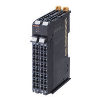
Omron Sysmac NX-HAD Series User Manual (306 pages)
Machine Automation Controller Analog I/O Units High-speed Analog Input Units
Brand:
Omron
| Category:
Controller
| Size: 7 MB
Table of Contents
Introduction
3
Table of Contents
5
Intended Audience
3
Applicable Products
3
Relevant Manuals
10
Manual Structure
11
Page Structure
11
Special Information
12
Precaution on Terminology
12
Terms and Conditions Agreement
14
Warranty, Limitations of Liability
14
Application Considerations
15
Disclaimers
15
Safety Precautions
17
Definition of Precautionary Information
17
Symbols
17
Warnings
18
Cautions
20
Precautions for Safe Use
21
Precautions for Correct Use
25
Regulations and Standards
27
Conformance to EU Directives
27
Conformance Requirement to EU Directives
28
Conformance to UL and CSA Standards
28
Conformance to Shipbuilding Standards
28
Conformance to KC Certification
28
Software Licenses and Copyrights
29
Unit Versions
30
Unit Versions and Support Software Versions
32
Related Manuals
33
Terminology
37
Revision History
40
Sections in this Manual
41
Features and System Configuration
43
Features
44
System Configuration
47
System Configuration in the Case of a CPU Unit
47
System Configuration of Slave Terminals
48
Example of Application System Configuration
49
Model
51
Model Notation
51
Model List
51
List of Functions
53
Support Software
54
A-7 Version Information with Communications Coupler Units
54
Specifications
56
General Specifications
56
Individual Specifications
56
Operating Procedures
57
Overall Procedure
57
Detailed Procedure for Configuring the Unit and Creating the User Program
58
Part Names
64
Indicators
65
TS Indicator
65
IN Indicator
66
Appearance Change of the Indicators
67
Terminal Blocks
68
Installation and Wiring
69
Section 4 Installation and Wiring
70
Installing NX Units
70
Restriction on Installation Orientation
70
Restriction on Adjacent Units
71
Power Supply Types and Wiring
72
Power Supply Types
72
I/O Power Supply Applications and Methods
72
Calculating the Total Current Consumption from I/O Power Supply
73
Wiring the Terminals
75
Wiring to the Screwless Clamping Terminal Blocks
75
Preventing Incorrect Attachment of Terminal Blocks
85
Checking the Wiring
89
Wiring External Devices
90
Terminal Block Arrangement
90
Wiring Examples
90
Precautions for Wiring
93
I/O Refreshing
101
5-1 I/O Refreshing
102
I/O Refreshing from CPU Units to NX Units
102
I/O Refreshing
102
I/O Refreshing from CPU Units or Industrial Pcs to Slave Terminal
103
Calculating the I/O Response Time of NX Units
104
I/O Refreshing Methods
106
Types of I/O Refreshing Methods
106
Setting the I/O Refreshing Methods
107
Restrictions in Refresh Cycles
108
I/O Refreshing Operation
109
Input Range and Converted Values
113
Voltage Input Range and Converted Values
114
Current Input Range and Converted Values
117
Specifications of I/O Data
120
Allocatable I/O Data
120
Data Details
124
Precautions for the I/O Data Size
130
Setting I/O Allocations with the Sysmac Studio
132
Displaying the Edit I/O Allocation Settings Window
132
Displayed I/O Allocation Settings
134
Configuring the I/O Allocation Settings
136
List of Settings
138
Functions
143
Function Block Diagram
145
Selecting Channel to Use
146
Function Applications and Overview
146
Details on the Function
146
Setting Method
147
A-9 Edit Unit Operation Settings Tab
147
Input Range Selection
148
Function Applications and Overview
148
Details on the Function
148
Setting Method
148
Number of Samplings Setting
150
Function Applications and Overview
150
Details on the Function
150
Setting Method
153
Checking the Sampling Settings
153
Digital Filtering
160
Function Applications and Overview
160
Details on the Function
160
Setting Method
169
Checking the Digital Filter Settings
170
Input Disconnection Detection
171
Function Applications and Overview
171
Details on the Function
171
Setting Method
172
Over Range/Under Range Detection
173
Function Applications and Overview
173
Details on the Function
173
Setting Method
174
User Calibration
175
Function Applications and Overview
175
Details on the Function
175
Setting Method
176
A-10 Displaying the User Calibration Window
176
Zero Set/Reset
180
Function Applications and Overview
180
Details on the Function
180
Setting Method
181
8-10 Trigger Input
182
Function Applications and Overview
182
Details on the Function
182
Identifying the Analog Input Value When Trigger Input was Turned on
187
Setting Method
189
8-11 Input Filter
190
Function Applications and Overview
190
Details on the Function
190
Setting Method
191
Troubleshooting
193
Section 9 Troubleshooting
194
How to Check for Errors
194
Checking for Errors with the Indicators
195
Checking for Errors and Troubleshooting on the Support Software
197
Checking for Errors from the Sysmac Studio
197
Checking for Errors from Support Software Other than the Sysmac Studio
198
Event Codes and Corrections for Errors
198
Meaning of Error
204
Resetting Errors
227
Unit-Specific Troubleshooting
228
Analog Input Value When an Error Occurs
231
Troubleshooting Flowchart
232
Inspection and Maintenance
233
Cleaning and Inspection
233
Cleaning and Inspection
234
Cleaning
234
Periodic Inspections
234
Maintenance Procedures
237
Appendices
239
A-1 Data Sheet
240
Model List
240
A-1-2 High-Speed Analog Input Units
241
High-Speed Analog Input Units
241
A-2 Dimensions
249
Programming Examples for Analog Input Data Collection with the Library
251
A-3-1 System Configuration
251
A-3-2 Programming Example
251
System Configuration
251
Programming Example
251
Connection to the Communications Coupler Unit
255
A-3-3 Connection to the Communications Coupler Unit
255
A-4 Digital Filter Design with the Library
259
A-4-1 System Configuration
259
A-4-2 Digital Filter Design Examples
259
System Configuration
259
Digital Filter Design Examples
259
A-4-3 Programming Example
263
Programming Example
263
A-4-4 Connection to the Communications Coupler Unit
272
A-5 List of NX Objects
276
A-5-1 Format of NX Object Descriptions
276
A-5-2 Unit Information Objects
276
A-5-3 Objects that Accept I/O Allocations
278
A-5-4 Other Objects
283
A-6 Version Information with CPU Units
289
A-6-1 Relationship between Unit Versions of Units
289
Version Information with Communications Coupler Units
290
Connection to an Ethercat Coupler Unit
290
Displaying the Edit Unit Operation Settings Tab Page
292
A-8-1 Connection to the CPU Unit
292
A-8-2 Slave Terminal
293
A-9 Edit Unit Operation Settings Tab Page
295
A-10-1 Connection to the CPU Unit
297
A-10-2 Slave Terminal
298
Advertisement
Advertisement
Related Products
Omron Sysmac NX701
Omron Sysmac NX A Series
Omron Sysmac NX E Series
Omron Sysmac NX-ILM Series
Omron SYSMAC NX-ILM Series
Omron SYSMAC One NSJ Series
Omron SYSMAC NY Series
Omron SYSMAC NJ Series
Omron SYSMAC SRM1
Omron sysmac EtherCAT NJ301 Series
Omron Categories
Blood Pressure Monitor
Controller
Accessories
Switch
Inverter
More Omron Manuals
Login
Sign In
OR
Sign in with Facebook
Sign in with Google
Upload manual
Upload from disk
Upload from URL