Table of Contents
Advertisement
Operations Manual
DOPSM2064X012
April 2019
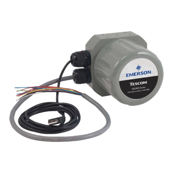
ER5000 Series
Do not attempt to select, install, use or maintain
this product until you have read and fully
understood the
Precautions
www.emerson.com
User Manual
Safety, Installation & Operations
section of this manual.
WARNING
If your application is rated as a Hazardous Location,
you MUST use model ER5050. Models ER5000,
ER5020, ER5040, ER5100 and ER5110 are not
intended for or rated for use in Hazardous Locations.
Advertisement
Table of Contents

Related Manuals for Emerson Tescom ER5000 Series


Summary of Contents for Emerson Tescom ER5000 Series
- Page 1 Hazardous Locations. ER5000 Series User Manual Do not attempt to select, install, use or maintain this product until you have read and fully understood the Safety, Installation & Operations Precautions section of this manual. www.emerson.com...
- Page 2 & afety nStallatIon peratIonS recautIonS...
-
Page 3: Tescom™ Electronic Controllers
ER5000 — Safety, Installation & Operations Precautions TESCOM™ ELECTRONIC CONTROLLERS WARNING CAUTION SAFETY PRECAUTIONS DO NOT ATTEMPT TO SELECT, INSTALL, USE OR MAINTAIN THIS Read and understand the user’s manual before operating the controller. CONTROLLER OR ACCESSORY UNTIL YOU HAVE READ AND FULLY UNDERSTOOD THESE INSTRUCTIONS. - Page 4 ER5000 — Safety, Installation & Operations Precautions 10. Clearly establish flow direction of the fluid before installation of controllers, 22. Users must test under normal operating conditions to determine suitability of regulators, valves and accessories. It is the responsibility of the user to install materials in an application.
- Page 5 ER5000 — Safety, Installation & Operations Precautions INSTALLATION Inspect the controller and accessories for physical damage and contamination. WARNING Do not connect the controller or accessory if you detect oil, grease or damaged parts. If the controller or accessory is damaged, contact your local TESCOM™ SAFE COMPONENT SELECTION representative to have the controller cleaned or repaired.
-
Page 6: Tescom Regulators
ER5000 — Safety, Installation & Operations Precautions TESCOM™ REGULATORS WARNING CAUTION SAFETY PRECAUTIONS DO NOT ATTEMPT TO SELECT, INSTALL, USE OR MAINTAIN THIS Inspect the regulator, valve and accessories before each use. REGULATOR, VALVE OR ACCESSORY UNTIL YOU HAVE READ AND FULLY UNDERSTAND THESE INSTRUCTIONS. - Page 7 ER5000 — Safety, Installation & Operations Precautions 10. Regulators are not shut-off devices. Install a pressure relief device downstream 20. Some fluids when burning do not exhibit a visible flame. Use extreme caution of the regulator to protect the process equipment from overpressure when inspecting and/or servicing systems using flammable fluids to avoid conditions.
- Page 8 ER5000 — Safety, Installation & Operations Precautions INSTALLATION WARNING CAUTION Investigate and apply the most recent standards for Hazardous Locations for your area set by ANSI, ISO and OSHA, as well as all electrical codes and fire and PROPER COMPONENT SELECTION safety standards, to determine if your application will require a Hazardous Consider the total system design when selecting a component for use in Location model.
-
Page 9: Table Of Contents
able of ontentS... -
Page 10: Table Of Contents
ER5000 — Table of Contents Table of Contents What’s New Getting Started New Features ....26 Before You Begin ....58 Safety, Installation &... - Page 11 ER5000 — Table of Contents The ERTune Program Voltage/Current Select Jumpers ..80 4–20 mA External Feedback, Ground ™ Referenced Input, Feedback Signal Monitored LED Indicators ....81 by PC or PLC A/D Card Power Supply Wiring —...
- Page 12 ER5000 — Table of Contents ER5000 Single “Puff” Solenoid Control Variable ER5000 Pulse Mode Variables ER5000 Analog and Digital Output Variables ER5000 Pulse Width Modulation (PWM) Control Variables ER5000 Gain/Offset Variables ER5000 Control Limit Variables Control Limits for Specified Signals Certifications and Warranty Certifications .
-
Page 13: Conventions Of This Manual
ER5000 — Table of Contents Conventions of This Manual Navigating This Manual refer to Text formatted as gray and italic denotes a clickable cross Clicking any item in the Table of Contents moves you to that page reference. Clicking this text moves you to the referenced page in the manual. -
Page 14: Features And Specifications
eatureS and pecIfIcatIonS... -
Page 15: Er5000 Series Part Numbering System
ER5000 Series — Features and Specifications ER5000 Series Part Numbering System ER5000 Standard Features As Figure 1 indicates, several base styles are available, including a • USB and RS485 communications compact OEM model for tight spaces where the NEMA 4 enclosure •... -
Page 16: Er5000 Dimensions - Side Views
ER5000 Series — Features and Specifications ER5000 Dimensions – Side Views Contact the factory for dimensions and specifications of models ER5020, ER5040, ER5100 and ER5110. Refer to the ER5000 Series Part Numbering System. 3.90 Inlet Port Exhaust Port [99.0] Gauge Port 1/8–27 NPTF 1/8–27 NPTF 1/8–27 NPTF... -
Page 17: Er5000 Dimensions - Top And Bottom View
ER5000 Series — Features and Specifications ER5000 Dimensions – Top and Bottom View Contact the factory for dimensions and specifications of models ER5020, ER5040, ER5100 and ER5110. Refer to the ER5000 Series Part Numbering System. 3.72 Top View [94.5] ER5000 Series Electropneumatic Controller All dimensions are called out in inches [millimeters]... -
Page 18: Er5050 Hazardous Location Model
ER5000 Series — Features and Specifications ER5050 Hazardous Location Model Dimensions – Side Views Contact the factory for dimensions and specifications of models ER5020, ER5040, ER5100 and ER5110. Refer to the ER5000 Series Part Numbering System. 4.09 Inlet Port Exhaust Port [103.8] Gauge Port 1/8–27 NPTF... -
Page 19: Er5050 Hazardous Location Model
ER5000 Series — Features and Specifications ER5050 Hazardous Location Model Dimensions – Top and Bottom View Contact the factory for dimensions and specifications of models ER5020, ER5040, ER5100 and ER5110. Refer to the ER5000 Series Part Numbering System. Top View 3.72 [94.5] Cover Lock Screw... -
Page 20: Er5000 Specifications
ER5000 Series — Features and Specifications ER 5000 Specifications Contact the factory for dimensions and specifications of models ER5020, ER5040, ER5100 and ER5110. Refer to the ER5000 Series Part Numbering System. Enclosure Power Requirement Type 4X, IP66. If the two 1/2-14 NPTF ports are unused, properly Voltage: 24V DC (22V DC to 28V DC) seal with a plug. - Page 21 ER5000 Series — Features and Specifications ER 5000 Specifications (cont.) RS485 Communication Interface Digital Inputs Networking: Up to 32 controllers on one network Voltage Range/Input Impedance: Maximum cable length: 4000 ft / 1219 m 4–20 mA: 250Ω Baud rate: 9600 1–5V: 220KΩ...
-
Page 22: Hazardous Location Model (Er5050) Specifications
ER5000 Series — Features and Specifications Hazardous Location Model (ER5050) Specifications Certifications Ports Refer to Hazardous Locations Special Requirements and Certification Conduit: 1/2" NPTF for the ER5050 for a complete list of hazardous location certifications. Pneumatic: 1/8" NPTF — Inlet, Exhaust and Gauge Ports 1/2"... - Page 23 ER5000 Series — Features and Specifications Hazardous Location Model (ER5050) Specifications (cont.) USB Communication Interface External Analog Input Impedance USB: 4–20 mA: 250Ω Maximum cable length: 15 ft / 4.5 m 1–5V: 220KΩ — single input pin to ground 1.7MΩ — differential input Connector: Mini-B 0–10V:...
-
Page 24: Accessories
ER5000 Series — Features and Specifications Accessories Part # Description 80129 1/8" NPTF male tube connector 250 mA / 24V DC power supply — input voltage 120V AC, 60 Hz 82575-25 82575-50 500 mA / 24V DC power supply — input voltage 120V AC, 60 Hz Potentiometer with digital display 82919 82948... -
Page 25: What's New
’... -
Page 26: New Features
ER5000 — What’s New New Features > Profiles can now include up to 100 command segments. Loop counts are now displayed in real time. • Built-in USB connectivity > For “F” model ER5000s, Profiles can now include these new Improved resolution for data acquisition with 16-bit A/D •... -
Page 27: Replacing An Er3000 With An Er5000
ER5000 — What’s New Replacing an ER3000 with an ER5000 Wiring for the “F” Model ER5000 For “F” model ER5000s, the 12-pin MTA connector and 8-pin Reference current Hazardous Location IMPORTANT! IMPORTANT! auxiliary MTA connector, which were previously fed by separate standards when replacing a Hazardous Location cables, are now fed by a single 20-wire cable. - Page 28 ER5000 — What’s New Using the ER5000 with ER3000 software If you wish to continue using the Windows Tune or other software that controlled your ER3000, you must install Jumper J9 to put the ER5000 into ER3000 Mode (refer to Figure 19).
-
Page 29: How It Works
orkS... -
Page 30: The Er5000: How It Works
ER5000 — How It Works The ER5000: How It Works Internal Feedback, which uses only the internal sensor ; • The ER5000 (Electronic Regulator 5000) is a microprocessor-based • External Feedback, which uses only the external source; PID (Proportional, Integral, Derivative) controller that brings precise •... -
Page 31: Understanding Pid Controllers
ER5000 — How It Works Understanding PID Controllers change in the setpoint, the controller works to raise or lower the system to the new target level. PID Controllers allow mechanical systems to operate at a high In either case, the controller continues to act until setpoint and level of precision and dependability with only occasional oversight feedback are equal. -
Page 32: Pid Controllers: Three Components Are Better Than One
ER5000 — How It Works direction. Significantly, Integral retains its value after the error • As the car passes the midpoint of the curve, the peripheral has been corrected. This is known as Integral Windup. force decreases and the wind dies down. Now the oversteer (Proportional and accumulated Integral) threatens to put •... -
Page 33: A Typical Pid Control System
ER5000 — How It Works • The second driver notices that there is a full cup of hot coffee A Typical PID Control System in the cup holder. This driver will take the curve as widely Figure 2 shows a simplified diagram of a typical PID and as slowly, as possible, because this driver’s primary goal control system. - Page 34 ER5000 — How It Works If setpoint and feedback match, the controller generates a zero Control systems based on just the Proportional term or just error and does not activate. the Proportional and Integral terms, are known as a P and PI configurations.
-
Page 35: Tuning A Pid Controller
ER5000 — How It Works Tuning a PID Controller default settings can be restored with the click of a button (see reset the ER5000 to its default PID settings). Tuning a controller is the process of selecting the optimal Using a few rules of thumb and the real-time visual feedback Kp, Ki and Kd settings to yield the best response. - Page 36 ER5000 — How It Works Figure 3 shows four typical response curves to a step The controller in Curve A responds with a Rise Time that is short (instantaneous) change in setpoint. and sharp. It also overcorrects (Overshoots) the error and oscillates around the new setpoint, a condition known as Ringing.
- Page 37 ER5000 — How It Works “critically damped,” with just enough Derivative added to eliminate • Windup can delay the controller’s response to new errors, as overshoot completely. Both tunings have no offset. Curve B accumulated errors must “spool out” before new errors can would be an optimal tuning for an application which can tolerate begin “charging up”...
- Page 38 ER5000 — How It Works Table 1 gives a summary of the rules of thumb for Proportional, Every system has unique characteristics, every operational Integral and Derivative. environment presents unique challenges and every application has unique requirements. Optimal tuning will invariably involve Table 1: Effect of P, I and D Increases on Response Curve of Controller both trial and error and compromise.
-
Page 39: The Er5000: Typical Application (Non-Hazardous Location)
ER5000 — Typical Application The ER5000: Typical Application (Non-Hazardous Location) Connection WARNING Investigate and apply the most recent standards for Hazardous Locations ER5000 Supply for your area set by ANSI, ISO and OSHA, as well as all electrical codes and Pressure 110 psig / 7.5 bar fire and safety standards, to determine if your application will require... - Page 40 ER5000 — Typical Application Every 25 milliseconds, the controller reads the feedback and compares it to the setpoint, which it receives from an external source or from a Profile in its onboard memory. If feedback is lower USB Connection than setpoint, the ER5000 activates the inlet valve, allowing Pilot Inlet Exhaust...
-
Page 41: A Note Concerning Non-Venting Regulators In Closed Loop Applications
ER5000 — Typical Application A Note Concerning Non-Venting Regulators in Closed • If the regulator is a metal diaphragm sensed regulator, the Loop Applications differential between the high downstream pressure beneath the diaphragm and the low (or even zero) pilot pressure above Non-venting regulators, which do not feature a regulator vent to the diaphragm can critically stress the diaphragm. -
Page 42: Monitoring System Control Limits
ER5000 — Typical Application Monitoring System Control Limits The default Condition is Inlet Closed/Exhaust Open, which ensures that a pressure reducing system will be vented if a limit is The ER5000 also can be configured to monitor the system and exceeded. -
Page 43: The Er5000: Control Modes
ER5000 — Control Modes The ER5000: Control Modes • There is a need to monitor downstream pressure. For example, if the output passes through a length of pipe to a vessel and it is Internal Feedback Mode expected that there will be pressure drops in the pipe, an external Internal Feedback Mode uses the ER5000’s internal sensor installed at the vessel will provide a more responsive sensor to monitor the pressure within the controller’s 0–100 psig /... -
Page 44: Glossary Of Terms
loSSary ermS... -
Page 45: Terms Relating To Pid Controllers And Controller Tuning
ER5000 — Glossary of Terms Terms Relating to PID Controllers and Controller Tuning D/A Cards causes the ER5000 to activate until the error is corrected. A positive Acronym for Digital To Analog Card. Used in PCs and PLCs to error causes the ER5000 to increase system pressure and a negative generate analog signals. - Page 46 ER5000 — Glossary of Terms Integral Integral Limits The component of a controller’s response that is based on Pair of filters which limit the amount of Integral Windup that can accumulated error within the system. Continues to accumulate as accumulate during Error correction.
- Page 47 ER5000 — Glossary of Terms to noise, at the expense of system stability and cycle life of the Overshoot Overcorrection due to a Proportional Integral setting that is ER5000’s solenoid valves. too high. Must be carefully controlled to keep response within the Offset operational parameters of the system.
- Page 48 ER5000 — Glossary of Terms Pressure Reducing Regulator Pulse Deadband Regulator that reduces high-pressure supplies of gas or liquid to a Stop-band filter that deactivates Pulse Mode within a set safe or usable level for an application. percentage range around Setpoint. Process Line Pulse Mode Area within a system where the activity takes place that is...
- Page 49 ER5000 — Glossary of Terms Regulator Setpoint Mechanical valve that dynamically controls the pressure of liquid The value that a PID Controller works to maintain within the system or gas in a process line by opening or closing in response to it controls.
- Page 50 ER5000 — Glossary of Terms Stable State System Pressure Any time that a PID Controller generates a zero Error for more The pressure of the gas or liquid in a Process Line that is controlled than one loop of monitoring and response. Proper Tuning aims to by the Regulator, which is controlled in turn by the...
- Page 51 ER5000 — Glossary of Terms Tuning The process of setting values for the Proportional, Integral Derivative constants within the PID Controller to achieve optimal performance. Variable Any configuration setting for the ER5000, such as the Proportional, Integral and Derivative constants, the setpoint value, the Control Mode or the Node Address.
-
Page 52: Terms Relating To Regulators
ER5000 — Glossary of Terms Terms Relating to Regulators dispose of excess liquid or gas expelled by the regulator’s vent valve. The vent port should never be plugged. Not all venting regulators Accuracy have this feature. Refer to Venting Regulator. The acceptable level of pressure variation for a Regulator under... - Page 53 ER5000 — Glossary of Terms Creep by inlet pressure moving through the valve. If inlet pressure An increase in the Outlet Pressure following Lock-up. Usually seen as decreases, for example when a supply cylinder starts to empty a slow, gradual pressure increase. Indicates a regulator leak and calls and the inlet pressure it supplies starts to decrease, this tips the for the immediate removal of the regulator for service.
- Page 54 ER5000 — Glossary of Terms Droop Sensing Element and causes the Control Element to respond Outlet Pressure change (offset) which occurs as flow rate by opening or closing the main valve. The three common types increases and which causes outlet pressure to stabilize at a rate of loading elements are Spring Loaded, Dome Loaded that is slightly offset from the expected...
- Page 55 ER5000 — Glossary of Terms Pilot Regulator Piston Device that controls pressure to the actuation port of a dome One type of Sensing Element. Used for high pressure applications, loaded or air actuated Regulator. In its simplest form, the ER5000 up to 30,000 psig / 2068 bar.
- Page 56 ER5000 — Glossary of Terms Sensing Element One of three basic elements of a pressure Regulator. Senses the changes in the control pressure (or process line) which allows the regulator to react and attempt to return to the original set pressure.
-
Page 57: Getting Started
ettInG tarted... -
Page 58: Before You Begin
ER5000 — Getting Started Before You Begin WARNING Investigate and apply the most recent standards for Hazardous Locations for your area set by ANSI, ISO and OSHA, as well as all electrical codes and fire and safety standards, to determine if your application will require a Hazardous Location model. WARNING Avoid personal injury or property damage from sudden release of pressure or bursting parts. -
Page 59: Er5000 Quick Reference: Jumpers, Terminal Blocks And Wires And Leds
ER5000 — Getting Started ER5000 Quick Reference: Jumpers, Terminal Blocks and Wires and LEDs “F” Models feature a single 20-wire cable Jumpers: 4–20 mA / 1–5V Models Terminal Blocks and Wires Standard Models feature a single 12-wire cable J3 Pins Wire Color Function Jumper J6... -
Page 60: Verify Your Shipment
ER5000 — Getting Started Verify your shipment CAUTION If you are replacing an ER3000 in an existing application, be sure that you have read Replacing an ER3000 with an ER5000 before you begin. WARNING If you are replacing a Hazardous Location ER3000 in an existing application, be sure that you have read Installing a Hazardous Location... -
Page 61: Additional Items Not Included
ER5000 — Getting Started Verify your shipment (cont.) Additional items not included: Additional items and tool you will need for an installation in a Hazardous Location: • 24V DC power supply* • Conduit and connectors rated for your Hazardous Location •... -
Page 62: Verify The Configuration Of Your Application
ER5000 — Getting Started Verify the configuration of your application + SUPPLY Power Supply +24V DC VIOLET ORANGE YELLOW GROUND GRAY WARNING Improper selection of controllers, regulators, valves or accessories USB Connection can cause death, serious injury and/or property damage. WARNING Installation in a hazardous location requires additional steps not described in this section. -
Page 63: Verify That All Operational Requirements Have Been Met
ER5000 — Getting Started Verify that all operational requirements Verify that all safety requirements have been met have been met Read and be sure you understand, all warnings and cautions in • Supply pressure must be clean, dry inert gas or Safety, Installation &... -
Page 64: Mount The Er5000 On The Regulator
ER5000 — Getting Started Mount the ER5000 on the regulator NOTE NOTE Your application may require additional fittings. CAUTION CAUTION WARNING WARNING WARNING Installation in a hazardous location requires additional steps not described in this section. Refer to Installing a Hazardous Location Model (ER5050) page 110... -
Page 65: Connect And Verify The Power Supply
ER5000 — Getting Started Connect and verify the power supply The ER5000 requires a 24V DC power supply, such as the TESCOM™ 82575-25 or 82575-50 power supply unit. WARNING • Select wiring and/or cable glands that are rated for the environment of use. - Page 66 ER5000 — Getting Started Connect and verify the power supply (cont.) Power Supply +24V DC VIOLET GROUND GRAY 1. Refer to Table 2 below and Figure 9 to verify correct wiring. Table 2: Main Cable Wiring for Power Supply J3 Pins Wire Color Function brown...
- Page 67 ER5000 — Getting Started Connect and verify the power supply (cont.) WARNING DO NOT open cover when an explosive atmosphere is present. Doing so can result in property damage, serious injury or death. Refer to Installing a Hazardous Location Model (ER5050) page 110 for more information.
-
Page 68: Verify The Jumper J6 Configuration
ER5000 — Getting Started Verify the Jumper J6 configuration WARNING The controller must be disconnected from the power supply before any additional wiring or change to jumper configuration is performed. Do not reconnect the power Jumper J6 supply until all additional wiring connections have been External Feedback made and are properly installed. - Page 69 ER5000 — Getting Started Connect the transducer wiring to provide a + SUPPLY Power Supply feedback signal VIOLET +24V DC ORANGE YELLOW GROUND GRAY WARNING The controller must be disconnected from the power supply before any additional wiring or change to jumper configuration is performed.
- Page 70 ER5000 — Getting Started Connect the transducer wiring to provide a feedback signal (cont.) 2. Connect the orange feedback input wire (Pin 3) to the signal output of the transducer, which is Pin 2 or B on TESCOM™ transducers. 3. Connect the positive wire from the 24V DC power supply to the power input of the transducer, which is Pin 1 or A on TESCOM transducers.
-
Page 71: Connect The Usb Cable (Not Supplied With Er5050)
ER5000 — Getting Started Mini-B Port Connect the USB cable (not supplied with ER5050) WARNING The controller must be disconnected from the power 90° Mini-B Connector supply before any additional wiring or change to jumper configuration is performed. Do not reconnect the power supply until all additional wiring connections have been made and are properly installed. -
Page 72: Install The Ertune™ Program
ER5000 — Getting Started Install the ERTune™ program 5. The ER5000 Setup Wizard screens are shown in Figure 14. Use the information from Step 1 to complete setup. IMPORTANT! IMPORTANT! If you are using Windows 8, be sure you For most screens, the default values will be correct for have read the note at the end of Step your application. -
Page 73: Connect Pressure To The System
ER5000 — Getting Started Connect pressure to the system WARNING • Never connect the controller or any associated equipment to a supply source having a pressure ER5000 Series Electropneumatic Controller greater than the maximum rated pressure of this controller or the associated equipment. •... - Page 74 ER5000 — Getting Started Connect pressure to the system (cont.) c. Leave the Gauge Port plugged to prevent leakage or attach a pressure gauge, as shown in Figure 16 on the previous page. NOTE NOTE For side-mounted applications, the Gauge Port can be used as the outlet.
-
Page 75: Start Up And Tune The System
ER5000 — Getting Started Start up and tune the system + SUPPLY Power Supply +24V DC VIOLET ORANGE WARNING YELLOW GROUND GRAY • Start up sequence for electropneumatic controllers is: a. Feedback loop must be installed and operational. USB Connection b. -
Page 76: Installation Variations
nStallatIon arIatIonS... -
Page 77: Before You Begin
ER5000 — Installation Variations Before You Begin WARNING Investigate and apply the most recent standards for Hazardous Locations for your area set by ANSI, ISO and OSHA, as well as all electrical codes and fire and safety standards, to determine if your application will require a Hazardous Location model. If your application requires a Hazardous Location model (ER5050), refer to Installing a Hazardous Location Model (ER5050) -
Page 78: Er5000 Installation Variations - Wiring Diagrams
ER5000 — Installation Variations ER5000 Installation Variations — Wiring Diagrams The ER5000 has a wide range of wiring options, allowing it to be configured for virtually any application requirement. If your application calls for a variation on the standard installation, use the diagrams on the following pages to build a complete configuration. Note that in your actual application, multiple wires may terminate at the same connection: for example, the violet wire (Pin 7), which is the (+) connection to the power source, may also connect directly to the transducer or other external devices. -
Page 79: Terminal Blocks And Wires
ER5000 — Installation Variations Terminal Blocks and Wires There are two terminal blocks on the control board of the Wires are color coded for easy identification. Wires that feed the ER5000. The 12-pin J3 terminal block is active for all models of the J3 terminal block are solid colors and wires that feed the J4 block controller. -
Page 80: Voltage/Current Select Jumpers
ER5000 — Installation Variations Jumper J6 Jumper J14 Voltage/Current Select Jumpers External Feedback Auxiliary Input #1 ON = 4–20 mA ON = 4–20 mA OFF = 1–5V OFF = 1–5V WARNING Jumper J5 The controller must be disconnected from the power supply before Jumper J15 Setpoint any additional wiring or change to jumper configuration is... -
Page 81: Led Indicators
ER5000 — Installation Variations The recommended configuration for the Ground Filter The LEDs can help you troubleshoot controllers that are not Bypass jumper (J1) is not installed (OFF). Installing this jumper functioning properly. For further information, refer to the connects signal ground directly to the power supply ground. Troubleshooting section. -
Page 82: Power Supply Wiring - All Applications
ER5000 — Installation Variations Power Supply Wiring — All Applications Refer to Table 4 to verify correct wiring. Table 4: Wiring to 24V DC Power Supply All ER5000s, regardless of configuration or application, must first J3 Pins Wire Color Function brown +setpoint input be wired to a 24V DC power supply, as shown in Figure 21. -
Page 83: Analog Setpoint Source - Potentiometer
ER5000 — Installation Variations Setpoint Wiring Variations WARNING The controller must be disconnected from the power Analog Setpoint Source — Potentiometer supply before any additional wiring or change to jumper configuration is performed. Do not reconnect Figure 22 shows correct wiring to provide a 0–5V signal to the the power supply until all additional wiring connections analog setpoint from a potentiometer. -
Page 84: Analog Setpoint Source - Current/Voltage
ER5000 — Installation Variations Setpoint Wiring Variations WARNING The controller must be disconnected from the power Analog Setpoint Source — Current/Voltage supply before any additional wiring or change to jumper configuration is performed. Do not reconnect the power Figure 23 shows how to provide the analog setpoint from an supply until all additional wiring connections have been made active variable current or voltage supply. -
Page 85: Analog Setpoint Source - Passive Pc Or Plc D/A Card
ER5000 — Installation Variations Setpoint Wiring Variations WARNING The controller must be disconnected from the power supply before Analog Setpoint Source — Passive PC or PLC D/A Card any additional wiring or change to jumper configuration is performed. Do not reconnect the power supply until all additional Figure 24 shows correct wiring to provide an analog setpoint from wiring connections have been made and are properly installed. -
Page 86: Analog Setpoint Source - Active Pc Or Plc D/A Card
ER5000 — Installation Variations Setpoint Wiring Variations WARNING The controller must be disconnected from the power supply before Analog Setpoint Source — Active PC or PLC D/A Card any additional wiring or change to jumper configuration is performed. Do not reconnect the power supply until all additional Figure 25 shows correct wiring to provide an analog setpoint from wiring connections have been made and are properly installed. -
Page 87: Profile With External Control/Digital Inputs
ER5000 — Installation Variations Setpoint Wiring Variations WARNING The controller must be disconnected from the power supply before Profile with External Control/Digital Inputs any additional wiring or change to jumper configuration is performed. Do not reconnect the power supply until all additional NOTE NOTE This feature is only available on “F”... - Page 88 ER5000 — Installation Variations Profile with External Control/Digital Inputs (cont.) Additionally, the Digital Input push button can be used if the “Digital Input” function has been used within the Profile. This allows an operator the flexibility to wait until an event has occurred, such as changing to the next device.
-
Page 89: Digital Setpoint Source - Rs485 Connection, Rs232 To Rs485 Converter (Tescom™ Model #85061)
ER5000 — Installation Variations Setpoint Wiring Variations WARNING Digital Setpoint Source — RS485 Connection, The controller must be disconnected from the power supply before any additional wiring or change to jumper configuration is RS232 to RS485 Converter (TESCOM™ Model #85061) performed. -
Page 90: Digital Setpoint Source - Rs485 Connection, Usb To Rs485 Converter (Tescom Model #82948)
ER5000 — Installation Variations Setpoint Wiring Variations WARNING Digital Setpoint Source — RS485 Connection, The controller must be disconnected from the power supply before any additional wiring or change to jumper configuration is USB to RS485 Converter (TESCOM™ Model #82948) performed. -
Page 91: Digital Setpoint Source - Rs485 Network
ER5000 — Installation Variations Setpoint Wiring Variations WARNING Digital Setpoint Source — RS485 Network, RS232 The controller must be disconnected from the power supply before to RS485 Converter any additional wiring or change to jumper configuration is (TESCOM™ Model #85061) performed. - Page 92 ER5000 — Installation Variations Digital Setpoint Source — RS485 Network, RS232 to RS485 Converter (cont.) (TESCOM™ Model #85061) Refer to Table 12 to verify correct wiring. Each ER5000 in the network must be assigned a unique Node Address. All ER5000s are assigned a default Node Address of 250; Table 12: Wiring for Networked Connection (RS232 to RS485 Converter) therefore, the addresses must be changed to allow them to all J3 Pins...
-
Page 93: Digital Setpoint Source - Rs485 Network, Usb To Rs485 Converter (Tescom Model #82948)
ER5000 — Installation Variations Setpoint Wiring Variations WARNING Digital Setpoint Source — RS485 Network, The controller must be disconnected from the power supply before USB to RS485 Converter any additional wiring or change to jumper configuration is (TESCOM™ Model #82948) performed. - Page 94 ER5000 — Installation Variations Digital Setpoint Source — RS485 Network, USB to RS485 Converter (cont.) (TESCOM™ Model #82948) Refer to Table 13 to verify correct wiring. Each ER5000 in the network must be assigned a unique Node Address. All ER5000s are assigned a default Node Address of 250; Table 13: Wiring for Networked Connection (USB to RS485 Converter) therefore, the addresses must be changed to allow them to all J3 Pins...
-
Page 95: Feedback Wiring Variations
ER5000 — Installation Variations Feedback Wiring Variations WARNING The controller must be disconnected from the power supply before Two Wire Transducer any additional wiring or change to jumper configuration is performed. Do not reconnect the power supply until all additional The correct wiring for two wire transducers is shown in Figure 31. -
Page 96: Three Wire Transducer
ER5000 — Installation Variations Feedback Wiring Variations WARNING The controller must be disconnected from the power supply before Three Wire Transducer any additional wiring or change to jumper configuration is performed. Do not reconnect the power supply until all additional The correct wiring for three wire transducers is shown in Figure 32. -
Page 97: Four Wire Transducer
ER5000 — Installation Variations Feedback Wiring Variations WARNING The controller must be disconnected from the power supply before Four Wire Transducer any additional wiring or change to jumper configuration is performed. Do not reconnect the power supply until all additional The correct wiring for four wire transducers is shown in Figure 33. -
Page 98: Ma External Feedback, Floating Input, Feedback Signal Monitored By Pc Or Plc A/D Card
ER5000 — Installation Variations Feedback Wiring Variations WARNING The controller must be disconnected from the power supply 4–20 mA External Feedback, Floating Input, Feedback before any additional wiring or change to jumper Signal Monitored by PC or PLC A/D Card configuration is performed. -
Page 99: Ma External Feedback, Ground Referenced Input, Feedback Signal Monitored By Pc Or Plc A/D Card
ER5000 — Installation Variations Feedback Wiring Variations WARNING The controller must be disconnected from the power supply before 4–20 mA External Feedback, Ground Referenced Input, any additional wiring or change to jumper configuration is Feedback Signal Monitored by PC or PLC A/D Card performed. -
Page 100: Two Wire Transducer, Pc Or Plc A/D Card Used To Monitor Voltage Produced By The 4-20 Ma External Feedback
ER5000 — Installation Variations Feedback Wiring Variations WARNING The controller must be disconnected from the power supply before Two Wire Transducer, PC or PLC A/D Card Used to Monitor any additional wiring or change to jumper configuration is Voltage Produced by the 4–20 mA External Feedback performed. -
Page 101: Three Wire Transducer, Pc Or Plc A/D Card Used To Monitor Voltage Produced By The 4-20 Ma External Feedback
ER5000 — Installation Variations Feedback Wiring Variations WARNING The controller must be disconnected from the power supply before Three Wire Transducer, PC or PLC A/D Card Used to Monitor any additional wiring or change to jumper configuration is Voltage Produced by the 4–20 mA External Feedback performed. -
Page 102: Four Wire Transducer, Pc Or Plc A/D Card Used To Monitor Voltage Produced By The 4-20 Ma External Feedback
ER5000 — Installation Variations Feedback Wiring Variations WARNING The controller must be disconnected from the power supply before Four Wire Transducer, PC or PLC A/D Card Used to Monitor any additional wiring or change to jumper configuration is Voltage Produced by the 4–20 mA External Feedback performed. -
Page 103: Switch Feedback Control To A Second Feedback Source
ER5000 — Installation Variations Feedback Wiring Variations VIOLET Switch Feedback Control to a Second Feedback Source ORANGE NOTE NOTE This feature is only available on “F” models of the ER5000. In “F” model ER5000s, the feedback source can easily be switched CAUTION CAUTION between two feedback sources. -
Page 104: Wiring Variations For Additional Functions
ER5000 — Installation Variations Switch Feedback Control to a Second Feedback Source (cont.) Wiring Variations for Additional Functions WARNING Monitoring Additional Analog Inputs The controller must be disconnected from the power supply before The ER5000 can monitor signals from a number of analog sources, any additional wiring or change to jumper configuration is as well as monitoring the state of internal variables, during normal performed. -
Page 105: Monitoring The Er5000'S Internal Sensor Using The Analog Output, 4-20 Ma Wiring
ER5000 — Installation Variations Wiring Variations for Additional Functions WARNING The controller must be disconnected from the power supply before Monitoring the ER5000’s Internal Sensor Using the any additional wiring or change to jumper configuration is Analog Output, 4–20 mA Wiring performed. -
Page 106: Monitoring The Er5000'S Internal Sensor Using The Analog Output, 0-10V Wiring
ER5000 — Installation Variations Wiring Variations for Additional Functions WARNING The controller must be disconnected from the power supply before Monitoring the ER5000’s Internal Sensor Using the any additional wiring or change to jumper configuration is Analog Output, 0–10V Wiring performed. -
Page 107: Digital Outputs
ER5000 — Installation Variations Wiring Variations for Additional Functions WARNING The controller must be disconnected from the power supply before Digital Outputs any additional wiring or change to jumper configuration is NOTE NOTE performed. Do not reconnect the power supply until all additional This feature is only available on “F”... - Page 108 ER5000 — Installation Variations Digital Outputs (cont.) The outputs can be toggled using a PC computer program or as part of a Profile and can be used to trigger a process in another part of the system, such as to turn on an audio or visual alarm or to start a conveyor belt.
-
Page 109: Suspend Mode
ER5000 — Installation Variations Wiring Variations for Additional Functions WARNING The controller must be disconnected from the power supply before Suspend Mode any additional wiring or change to jumper configuration is performed. Do not reconnect the power supply until all additional NOTE NOTE This feature is only available on “F”... -
Page 110: Installing A Hazardous Location Model (Er5050)
ER5000 — Installation Variations Installing a Hazardous Location Model (ER5050) Conduit O-Ring Set Screw WARNING Ground Wire Install conduit rated for your Hazardous Location Hazardous using local and national electrical codes which Location Hub Junction Box Rated or Cable Gland apply to the application. -
Page 111: The Ertune Program
™ p roGram... - Page 112 ER5000 — The ERTune™ Program Navigating the Screen: Tabs, The Plot Screen Menus — The PID Control Panel The Main Axis Menu The Proportional Controller Panels, Windows and Fields Time Proportional Tuning Tips Minimum Vertical The Derivative Controller Maximum Vertical Derivative Tuning Tips The ERTune™...
- Page 113 ER5000 — The ERTune™ Program The ERTune™ Program: Modify The Configure Tab ....178 Delete Power User The Mechanical Regulator Panel The Commands in the Profile Builder The ER Settings Panel The Power User Tab .
- Page 114 ER5000 — The ERTune™ Program Using The Program: Tasks, The Tab Area ....129 To reset the secondary axis to its original values using the Secondary Axis Menu To display the Power User Tab Features and Functions To change the range of feedback values...
- Page 115 ER5000 — The ERTune™ Program The ERTune™ Program: Power User 187 To add the Integral Term The Configure Tab ....178 To limit the effect of the Integral Term To change the Regulator Series The Power User Tab .
- Page 116 ™ p roGram aSIc eatureS...
- Page 117 ERTune. On PCs running previous versions of Windows, this is located at: C: -> Documents and Settings -> All Users -> Application Data -> Emerson -> ERTune This folder is the default location for configuration files, Profiles and data acquisition files. The Windows Navigator window will default to this folder.
- Page 118 ER5000 — The ERTune™ Program: Basic Features Installing the ERTune™ Program To install the ERTune™ program 1. Download the ER5000 Software and Manual file which can be The ERTune™ program provides an intuitive interface to found at TESCOM.com under the “Download ER5000 Software customize the performance of the ER5000 to meet the specific and Manual”...
- Page 119 ER5000 — The ERTune™ Program: Basic Features To open the ERTune program The ER5000 device driver ™ The ER5000DR device driver must be installed in your computer IMPORTANT! IMPORTANT! The ER5000 controller must be powered up and to allow for direct USB connection between the controller and connected to the computer for the ERTune™...
- Page 120 ER5000 — The ERTune™ Program: Basic Features Next > 1. Click the button. The Node and Model window opens. If this is the first time the ER5000 has been connected to the computer, you will be taken through the steps to set up the 2.
- Page 121 ER5000 — The ERTune™ Program: Basic Features ER Model 3. In the drop-down list, select the ER model number 6. Select the Control Mode that is appropriate for your Next > that matches the model number of your controller. application and click the button.
- Page 122 ER5000 — The ERTune™ Program: Basic Features Next > 7. The label you see for the field set in this window depends on 8. Click the button. The Mechanical Regulator Information the Control Mode you selected in Step 6. window opens. •...
- Page 123 ER5000 — The ERTune™ Program: Basic Features Next > 10. Click the button. The PID Download window opens. The ER5000 software includes PIDs specifically tuned for most TESCOM™ regulators, as well as default PIDs that are Other None used if has been selected.
- Page 124 ER5000 — The ERTune™ Program: Basic Features You should consider using this feature if your application meets CAUTION one or both of these conditions: Regulator Diaphragm Protection is not recommended for • The regulator you will be using is a non-venting, metal applications which do not meet one or both of these conditions.
- Page 125 ER5000 — The ERTune™ Program: Basic Features If the ERTune™ program does not open To open the ERTune™ program without a controller connected Start -> All Programs -> ERTune -> ERTune Simulator. 1. The Comm Error window opens. 1. Select 2.
- Page 126 ER5000 — The ERTune™ Program: Basic Features The ERTune™ Program User Interface Click a heading to learn more about the features and functions of that area of the interface The Menu Bar The Plot Screen The Tab Area The Plot Screen Variable Controls The Footer Area...
- Page 127 ER5000 — The ERTune™ Program: Basic Features Navigating the ERTune™ User Interface The Node Menu The Menu Bar The menu bar displays three menu items on the left. NOTE NOTE If the ER5000 does not detect a feedback signal, a warning will The Node menu has two commands.
- Page 128 ER5000 — The ERTune™ Program: Basic Features Search Node The Help Menu This command opens the Search Nodes window. The ERTune™ program searches through all 250 Node Addresses and generates a list of active nodes. To select a controller from the list of active nodes The Help Menu has three commands.
- Page 129 ER5000 — The ERTune™ Program: Basic Features The Tab Area The Configure Tab The five tabs on the left of the screen organize the controls and entry fields of the ERTune™ program. This tab displays the controls for setting and changing basic A brief explanation of each tab is given below.
- Page 130 ER5000 — The ERTune™ Program: Basic Features The Plot Screen If you add additional variables to the display using The Plot Screen Variable Controls, a secondary (right) vertical axis appears on the The Plot Screen gives you a precise visual display of the moment- right side of the Plot Screen to track these values.
- Page 131 ER5000 — The ERTune™ Program: Basic Features Figure 48 shows all the elements of the active Plot Screen display as the ER5000 responds to step changes in setpoint (red line). The response is tracked through the feedback (blue line). The main (left) vertical axis and the horizontal axis have been customized using the commands in...
- Page 132 ER5000 — The ERTune™ Program: Basic Features Resizing the Range Displayed by the Plot Screen Using the Mouse IMPORTANT! IMPORTANT! To zoom the vertical axis display Changes made to the Plot Screen display using the mouse or the Plot Screen menu commands only change the display of the Plot 1.
- Page 133 ER5000 — The ERTune™ Program: Basic Features To zoom the display of both the vertical and horizontal axes To return both axes to the default display settings 1. Drag a rectangular marquee within the active area of the 1. Double-click anywhere within the Plot Screen. Plot Screen.
- Page 134 ER5000 — The ERTune™ Program: Basic Features The Plot Screen Menu Bar Rescale Vertical This command resets the main axis to its original minimum and The Plot Screen Menu Bar displays two menus and two buttons. maximum values if they have been changed by the Maximum Vertical and/or Minimum Vertical commands.
- Page 135 ER5000 — The ERTune™ Program: Basic Features Minimum Vertical The Plot Screen Buttons — The Start Plot/Stop Plot Button This command allows you to set the minimum value of the This button toggles to start and stop the real-time display of the secondary axis.
- Page 136 ER5000 — The ERTune™ Program: Basic Features 2. Enter a new value. To change the horizontal axis using the Main Axis Menu Main Axis -> Time. The Enter Time window opens. 1. Select 3. Click OK. The display rescales using the new value. NOTE NOTE Repeat these steps for both menu items if you wish to set...
- Page 137 ER5000 — The ERTune™ Program: Basic Features The Plot Screen Variable Controls By default, the Plot Screen displays the setpoint and feedback values for your application. Using the controls in this area, you can track up to two additional variables. NOTE NOTE These variables can also be added to data acquisition files...
- Page 138 ER5000 — The ERTune™ Program: Basic Features To track an additional variable The first added variable appears as a green line. The NOTE NOTE Add Variable second added variable appears as a black line. 1. Click the button. CAUTION CAUTION Variable Name.
- Page 139 ER5000 — The ERTune™ Program: Basic Features To optimize the display when both additional variables have been added to the Plot Screen In many applications, the ranges for the first and second additional The “best of both worlds” approach in this scenario is to set the variable will vary widely.
- Page 140 ER5000 — The ERTune™ Program: Basic Features To change which variable is being tracked To change the secondary axis using the Secondary Axis Menu Down Arrow ( 1. Click the to open the drop-down list for the ▼ IMPORTANT! IMPORTANT! Changes made to the Plot Screen display using the Plot additional variable you wish to change.
- Page 141 ER5000 — The ERTune™ Program: Basic Features To change the range of feedback values tracked by the To change the display of the main (left) axis to the new range ERTune™ program Main Axis -> Rescale Vertical. 1. Select IMPORTANT! IMPORTANT! Changes made using the Range buttons in the Plot 2.
- Page 142 ER5000 — The ERTune™ Program: Basic Features The Footer Area The Footer Area at the bottom of the display screen shows the following information: • Model number of the ER5000 • Serial number of the ER5000 Node Address of the ER5000 •...
- Page 143 ER5000 — The ERTune™ Program: Basic Features The Tuning Tab: Controls and Functions for Tuning the ER5000 The controls in the Tuning Tab allow you to manually tune the ER5000 to achieve optimal performance for your application. The first time you open the ERTune™ program, the Tuning Tab will display the PID values that were set at the factory or that were downloaded to the controller during setup.
- Page 144 ER5000 — The ERTune™ Program: Basic Features Tuning the ER5000 Before You Begin If you are new to PID controllers, be sure that you have read the of the controller’s response characteristics. Your final tuning How It Works Glossary of Terms sections of this manual, as well should be done using a range that approximates typical as all cautions and warnings in the...
- Page 145 ER5000 — The ERTune™ Program: Basic Features The Setpoint Panel External Device Setpoint Source When this is selected, the ER5000 accepts digital setpoints (USB The fields in this panel allow you to select a setpoint source for or RS485) from an external device such as a PC. The setpoint tuning the ER5000 and set the parameters of the tuning session.
- Page 146 ER5000 — The ERTune™ Program: Basic Features To change a setpoint value during tuning ERTune Program Ramp Mode Setpoint Source 1. Enter a new value in either field. In Ramp Mode, the ERTune™ program changes the setpoint This may be done at any time. steadily from the current level to a target level over a set period of time, generating a gradual rise or fall in the Plot Screen.
- Page 147 ER5000 — The ERTune™ Program: Basic Features Profile Setpoint Source To tune the ER5000 using a Profile When this is selected, the ER5000 uses a Profile to control 1. Click the Profile Tab. setpoint changes. The Profile must be loaded in the controller. 2.
- Page 148 ER5000 — The ERTune™ Program: Basic Features The PID Control Panel NOTE NOTE The title of the PID Control Panel displays the current Control Mode of the ER5000. CAUTION CAUTION NOTE NOTE If the ER5000 is set to Cascade Mode, the PID Control Panel WARNING WARNING has separate displays for the internal and external PID controllers.
- Page 149 ER5000 — The ERTune™ Program: Basic Features The ER5000 can be reset to the default PID settings at any time. The Proportional Controller This slider sets the Proportional term for the ER5000. To reset the ER5000 to its default PID settings Proportional Tuning Tips Set Defaults 1.
- Page 150 ER5000 — The ERTune™ Program: Basic Features The Derivative Controller The Integral Controller This slider sets the Derivative term for the ER5000. This slider sets the Integral term for the ER5000. Derivative Tuning Tips Integral Tuning Tips • In most tuning applications, the Derivative term is first zeroed •...
- Page 151 ER5000 — The ERTune™ Program: Basic Features The Integral Limits Controllers These three controllers allow you to set a higher Integral term Deadband while minimizing detrimental effects such as windup. This controller sets a range around the setpoint where the Integral term will not respond to error.
- Page 152 ER5000 — The ERTune™ Program: Basic Features A Typical Step Tuning Example The Initial Settings • Setpoint Source: ERTune™ Program This section is an example of the proper sequence of steps to • Type: Toggle follow, as well as typical settings, for a step tuning session for •...
- Page 153 ER5000 — The ERTune™ Program: Basic Features To set the Proportional Term 4. Continue to toggle the setpoint. Note the change in the response of the ER5000. 1. Toggle the setpoint. 5. Continue to move the Proportional slider right until you 2.
- Page 154 ER5000 — The ERTune™ Program: Basic Features 6. Step back the Proportional slider to minimize To add the Derivative Term unwanted effects. 1. Move the Derivative slider slightly to the right or enter a higher number in the field next to the slider. 2.
- Page 155 ER5000 — The ERTune™ Program: Basic Features 3. Continue to increase the Derivative term until you have 4. Repeat the process until you note the effects of overdamping. stabilized the response. Figure 56: Typical Tuning: Overdamped Response A Derivative setting that is too high results in a slower rise time. Figure 55: Typical Tuning: Critically Damped 5.
- Page 156 ER5000 — The ERTune™ Program: Basic Features To add the Integral Term To limit the effect of the Integral Term using the Integral Limits 1. Move the Integral slider to the right or enter a value of 50. 1. Increase magnification in the Plot Screen to zoom in closely at the level of Setpoint 2 (75%).
- Page 157 ER5000 — The ERTune™ Program: Basic Features Maximum 5. If there is offset, move the slider slightly to the right, 8. Look closely for offset between the setpoint and feedback to increase the level of positive Integral that will be allowed level once the system reaches stable state.
- Page 158 ER5000 — The ERTune™ Program: Basic Features 11. If you note a delayed response to a change in setpoint or that To add Integral Deadband the changes to Integral Limits have re-introduced overshoot 1. Allow the ER5000 to cycle through the Plot Screen several that slowly settles into setpoint, these are signs of Integral times at the current setpoint.
- Page 159 ER5000 — The ERTune™ Program: Basic Features Cascade Tuning Cascade tuning is complex and can prove daunting for the • Alternate between increasing the Integral Term, then inexperienced user and should only be attempted if the system is increasing the Proportional Term, until you begin to see persistently unstable.
- Page 160 ER5000 — The ERTune™ Program: Basic Features The Profile Tab: Creating Multi-Step Command Sequences Profiles are multi-step command sequences for the ER5000. They require no previous programming experience on the part of the user to create and guide the ER5000 through everything from a simple start/stop operation to a sequence of setpoint changes that can include up to one hundred command lines and control loops that can run indefinitely.
- Page 161 ER5000 — The ERTune™ Program: Basic Features The Panels and Windows of the Profile Tab Profile Panel Holds buttons for printing, uploading and saving, as well as The Profile Panel has buttons for printing the current Profile, the Profile Window. uploading from or downloading to the ER5000 and opening from or saving to the PC.
- Page 162 ER5000 — The ERTune™ Program: Basic Features The Profile Panel The Profile Window The Profile Window shows the command lines of the currently The top panel of the Profile Tab shows the currently loaded Profile. loaded Profile. Selecting a command in the window opens it for editing in the Profile Builder.
- Page 163 ER5000 — The ERTune™ Program: Basic Features The Profile Builder Panel The Segment Editor Window There are three buttons in this window. The middle panel of the Profile Tab holds the tools for adding, modifying and deleting segments of the Profile. Insert This button adds a new segment to the Profile.
- Page 164 ER5000 — The ERTune™ Program: Basic Features To modify a segment in a Profile CAUTION 1. Click within the Profile Window to select the segment. It may If you are modifying a Profile that has been previously downloaded be necessary to scroll to locate the segment line. Download or saved, you must click the button to download the updated...
- Page 165 ER5000 — The ERTune™ Program: Basic Features The Commands in the Profile Builder Dwell Maintains the current setpoint for the amount of time, in seconds, The unit of measurement for the setpoint value parameter IMPORTANT! IMPORTANT! Time to Dwell (sec) entered in the entry field.
- Page 166 ER5000 — The ERTune™ Program: Basic Features Delta Change Variable Delta Initiates a step setpoint change by the value entered in the Sets the value of an internal variable of the ER5000, selected Amount Delta Amount Variable Value entry field. The value entered in the entry field from the drop-down list, to the value entered in the...
- Page 167 ER5000 — The ERTune™ Program: Basic Features Additional Commands Available for “F” Model ER5000s Soak Pauses the Profile while the ER5000 responds to a step setpoint Allows the Profile to respond to the current state of the system. change, then dwells at that setpoint for a specified amount of Checks whether a parameter of the current system status matches Error Band (psig) Condition, Operator and Value...
- Page 168 ER5000 — The ERTune™ Program: Basic Features Goto Go to Moves the Profile to the command segment entered in the Segment entry field. NOTE NOTE To execute a multi-line command sequence based on the same condition, use the Goto command together with the command, which CAUTION CAUTION...
- Page 169 ER5000 — The ERTune™ Program: Basic Features Digital Output (ER Outputs are Ports 3 & 4) Digital Input (ER Input is Port 3) Sends a signal to trigger a process in another part of the system. Pauses the Profile until the specified input is set to the specified Refer to the Digital Outputs wiring configuration for an example...
- Page 170 ER5000 — The ERTune™ Program: Basic Features The Data Tab The ER5000 can save data acquired during tuning sessions, as well as during normal operations after a triggering event has taken place. Data is written to a delimited text file that is saved to your computer and uses the .dat file extension.
- Page 171 ER5000 — The ERTune™ Program: Basic Features To add a variable using the Plot Screen Variable Controls To set or change the range for an added variable Add Variable 1. Click the button. IMPORTANT! IMPORTANT! Changes made using the Range buttons in the Plot Variable Name.
- Page 172 ER5000 — The ERTune™ Program: Basic Features The Acquisition Panel To control data collection manually Collection Time 1. Enter a value in the entry field that is The entry fields in this panel allow you to set the sample rate and considerably higher than your intended collection time.
- Page 173 ER5000 — The ERTune™ Program: Basic Features The Output Panel Delimiter Delimiter drop-down list sets the delimiter that separates the The entry fields in the Output Panel set the parameters of the data columns in the file. Select Space, Comma or Tab. .dat file.
- Page 174 ER5000 — The ERTune™ Program: Basic Features Collecting and Reviewing Data To start data collection Start DAQ 1. Click the button. The button changes to display Enter the file name, data delimiter and comment block IMPORTANT! IMPORTANT! Stop DAQ. before you begin data collection. The data file is saved automatically when the Collection Time ends.
- Page 175 ER5000 — The ERTune™ Program: Basic Features To view an acquired data file Plot File 1. Click the button. A Windows Explorer window opens. 2. Navigate to the .dat file you wish to view and double-click it OPEN or click the button.
- Page 176 ER5000 — The ERTune™ Program: Basic Features The Triggers Panel To collect data based on a triggered event Data acquisition can also be triggered automatically by events that happen during normal system operation. The fields in this 1. In the Triggers Panel, click the check box next to the input source or sources you wish to track.
- Page 177 ER5000 — The ERTune™ Program: Basic Features Start DAQ 3. Click the button. Triggering is activated and the Stop DAQ. button changes to display 4. When any of the triggering conditions is met, data acquisition will begin. The program alerts you that acquisition has been activated with a message in the Menu Bar.
- Page 178 ER5000 — The ERTune™ Program: Basic Features The Configure Tab The entry fields and list fields in this tab allow you to modify the system configurations of the ER5000 to match the requirements of your application. WARNING ™ Most controls in the ERTune program operate in real time and have an immediate effect on system performance.
- Page 179 ER5000 — The ERTune™ Program: Basic Features The Mechanical Regulator Panel The ER Settings Panel The fields in this panel display the series number, model number The fields in this panel control the basic configuration of the ER5000. and serial number for the regulator that the ER5000 controls. You enter this information during setup.
- Page 180 ER5000 — The ERTune™ Program: Basic Features ER Node Calibration This entry field allows you to change the Node Address of These entry fields allow for fine adjustment of the ER5000. the ER5000. The defaults meet the needs of most applications. However, your application may require an adjustment of these values to To change the Node Address of the ER5000 compensate for external transducers which require calibration,...
- Page 181 ER5000 — The ERTune™ Program: Basic Features The Control Limits Panel The entry fields in this panel allow you to set system Control The Control Limit Conditions provide added security in the event Limits which the ER5000 will then monitor. of a system failure such as broken transducer wiring, lack of supply pressure or pipe ruptures.
- Page 182 ER5000 — The ERTune™ Program: Basic Features To add a Control Limit for the ER5000 to monitor To remove a Control Limit 1. Enter a value in the entry field of the variable that 1. Enter a value that is beyond the limit for that field. It will you wish to monitor and press the Tab key.
- Page 183 ER5000 — The ERTune™ Program: Basic Features The Diaphragm Protection Panel CAUTION The entry fields in this panel allow you to enable Diaphragm Regulator Diaphragm Protection is not recommended for Protection for the connected regulator. applications which do not meet one or both of these conditions. To activate Regulator Diaphragm Protection Enable 1.
- Page 184 ER5000 — The ERTune™ Program: Basic Features The Diagnostic Tools Tab The buttons on this panel open troubleshooting tools and additional reference files for the ER5000. The System Check Panel Open button in this panel opens a presentation that offers additional information and tips on checking operational parameters for the ER5000.
- Page 185 ER5000 — The ERTune™ Program: Basic Features YES, CONTINUE TEST 2. To continue to the test, click the button. 7. The test begins. The program first tests the Inlet Valve. To abort the test so you can institute safety procedures, click NO, ABORT TEST button.
- Page 186 ER5000 — The ERTune™ Program: Basic Features For the Inlet Valve test, the controller exhausts all internal NOTE NOTE If the ER5000 is connected to a regulator when the Solenoid pressure to start with a reading of 400 (the initial value for Leak Test is run and a failure is recorded, it may indicate a leak in the CAUTION CAUTION...
- Page 187 ™ p roGram oWer...
- Page 188 ER5000 — The ERTune™ Program: Power User The Power User Tab This tab gives you access to advanced configuration options. Most applications of the ER5000 do not require access to this tab. NOTE NOTE The entry fields in this tab control the basic operational parameters of the ER5000.
- Page 189 ER5000 — The ERTune™ Program: Power User The Additional ER Settings Panel External Feedback Source To switch the external feedback source This field controls which feedback source displays in the Plot 1. Click the radio button next the source you wish to track. Screen when you have wired the ER5000 for multiple feedback sources.
- Page 190 ER5000 — The ERTune™ Program: Power User The Read/Write Panel 2. Select from the list of variables. 3. The Variable ID number displays to the right of the list. The The entry fields in this panel allow you to monitor and modify the variable value displays in the entry field.
- Page 191 ER5000 — The ERTune™ Program: Power User The Solenoid Settings Panel CAUTION The entry fields in this panel allow you to change the minimum Setting the minimum pulse width too high can cause the ER5000 pulse width for the inlet and exhaust solenoid valves in the ER5000. to activate in response to transient errors which do not require This setting changes the responsiveness of the controller.
- Page 192 ER5000 — The ERTune™ Program: Power User The Algorithm Update Rate Panel CAUTION This field allows you to change the rate at which the The Algorithm Update Rate controls the speed of response of the ER5000 operates. ER5000. The default values should not be changed if you are not certain how this will effect the performance of the controller.
- Page 193 ER5000 — The ERTune™ Program: Power User The Pulse Mode Panel Pulse mode responds to errors within the Integral Deadband range with short, pulsed, activation of the solenoid valves. The fields in this panel give you precise control over how the These pulsed responses continue until feedback falls within the ER5000 responds to errors which fall within the deadband set Pulse Mode Deadband range (in effect, the deadband within the...
- Page 194 ER5000 — The ERTune™ Program: Power User Deadband This is the Pulse Width Deadband, the “deadband within a deadband” of the Integral Deadband. When feedback falls within this inner range, Pulse Mode stops responding. Pulse Width Deadband is set to a much smaller level than Integral Deadband, allowing the ER5000 to respond to a very small level or error.
- Page 195 ER5000 — The ERTune™ Program: Power User The Power User Tab: The Password Panel 4. The password will become effective the next time the ERTune™ program is opened. The Enter Password window The fields in this panel allow you to add password protection to opens instead.
- Page 196 er5000 S oftWare eVelopment upport...
-
Page 197: Er5000 Software Development Support
ER5000 — ER5000 Software Development Support ER5000 Communication Requirements and you wish to daisychain them in the same network. You can link up to 32 ER5000s in a single network. The ER5000 communicates via USB or RS485. Wiring diagrams for RS485 communication can be found in •... -
Page 198: Windows Programming Examples
ER5000 — ER5000 Software Development Support You can also develop your own process control software to communicate with the ER5000. Typically, programmers use the Windows-based DLL to communicate with the ER5000. A 32-bit version of the dll, along with the source code, can be found in the ER5000 Software. -
Page 199: Accessing The Windows Dll File
ER5000 — ER5000 Software Development Support Accessing the Windows DLL File 2. The ER5000 User Support Software and Manual menu gives you access to the programs and reference materials. Click The TESCOM™ protocol, ER5000DLL.dll, allows easy access to the Resources button. -
Page 200: The Tescom Protocol
ER5000 — ER5000 Software Development Support The TESCOM™ Protocol Not all systems run on a Windows-compatible platform. TESCOM WriteNetVar This function is used to write to any of the ER5000 internal variables. provides two resources for non-typical applications, which can be Protocol found in the section of the ER5000 Software:... - Page 201 ER5000 — ER5000 Software Development Support Protocol To view the source code of the TESCOM™ protocol file 3. Click the button. 1. Download the ER5000 Software and Manual file which can be found at TESCOM.com under the “Download ER5000 Software and Manual” link. Once the file is downloaded, extract the zip file, click on the .exe file, and the ER5000 User Support Software and Manual menu will open.
-
Page 202: Troubleshooting
roubleShootInG... -
Page 203: Installation
.NET Framework 3.5, which is not installed by default in Windows 8. If you are using Windows 8, you will need to download and install .NET C: -> Documents and Settings -> All Users -> Application Data -> Emerson -> ERTune Framework 3.5 before installing the ERTune™ program. We have provided... - Page 204 Windows 8 users: You may need to disable Driver Signature Enforcement to install the ER5000 driver. We have provided C: -> Program Files (x86) -> Emerson -> ERTune step-by-step instructions for this task in Appendix A: Setting up the folder and click OK.
- Page 205 ER5000 — Troubleshooting Installation Browse... Click the button and navigate to the Installing the ER5000 USB Device Driver Manually C: -> Program Files -> Emerson -> ERTune folder. (Windows XP and earlier) Next > Then click the button. IMPORTANT! IMPORTANT! Windows 8 users: You may need to disable Driver Signature Enforcement to install the ER5000 driver.
-
Page 206: Operation
ER5000 — Troubleshooting Jumper J6 Jumper J14 Operation External Feedback Auxiliary Input #1 ON = 4–20 mA ON = 4–20 mA Checking the Configuration of the Jumpers OFF = 1–5V OFF = 1–5V Jumper J5 WARNING Jumper J15 Setpoint Auxiliary Input #2 The controller must be disconnected from the power supply before ON = 4–20 mA OFF = 1–5V... - Page 207 ER5000 — Troubleshooting Operation Checking the Configuration of the Jumpers (cont.) If Jumper J9 is ON, some of the new features of the ER5000 While it is rare, electrical noise can at times cause a problem in an will not function, including Suspend Mode and some Profile ER5000 control system.
- Page 208 ER5000 — Troubleshooting Operation Checking the LED Indicators WARNING The LEDs can help you troubleshoot controllers that are not functioning properly. Be aware that the controller is connected to the power supply and that critical components of the controller are exposed when the cover is removed to inspect the LED indicators.
- Page 209 ER5000 — Troubleshooting Operation Using the LED Indicators to Verify Power Supply During Using the LED Indicators to Verify RS485 Communication Power-up 1. Power up the ER5000 and verify the power supply, as 1. Power up the ER5000. described above. 2.
- Page 210 ER5000 — Troubleshooting Operation 1. Check all power and communication wiring per your application. Opening the ERTune™ Program Search Ports 2. Click the button. The ERTune™ program scans all COM ports that are in use. The ER5000 must be powered up and connected to the IMPORTANT! IMPORTANT! PC via USB or RS485 in order to open the ERTune™...
- Page 211 ER5000 — Troubleshooting Operation Checking the ERTune™ Menu Bar for Warnings The Menu Bar of ERTune™ program displays two No Feedback and Simulation. warnings: Simulation warning indicates that the ERTune™ program has been opened in Simulation Mode. In Simulation Mode, the program responds No Feedback warning indicates that the program is normally to controls.
- Page 212 ER5000 — Troubleshooting Operation Checking the Pressure Connections if the ER5000 Does Not Respond Properly to Setpoint Changes WARNING • Never connect the controller or any associated equipment to a supply source having a pressure greater than the maximum rated ER5000 Series pressure of this controller or the associated equipment.
- Page 213 ER5000 — Troubleshooting Operation Checking the Pressure Connections if the ER5000 Does Not Respond Properly to Setpoint Changes (cont.) • Inlet pressure should be 110 psig / 7.5 bar, with a maximum of 120 psig / 8.2 bar. ER5000 Series Electropneumatic Controller NOTE NOTE...
- Page 214 ER5000 — Troubleshooting Operation Checking the Pressure Connections if the ER5000 Does Not Respond Properly to Setpoint Changes (cont.) 5. Make sure that a Control Limit has not been triggered. Refer The Control Limits Panel for more information. 6. If the problem persists, use The Plot Screen Buttons —...
- Page 215 ER5000 — Troubleshooting Operation Checking the Solenoid Valves for Leaks The ERTune™ program includes an automated test for the Inlet and Exhaust valves of the controller. Refer to The ER Solenoid Leak Test Panel section for a step-by-step explanation of the process. Checking Other Components of the Application for Leaks TESCOM™...
-
Page 216: Rs485 Communication
ER5000 — Troubleshooting RS485 Communication TESCOM™ Model # 82948 USB to RS485 Converter Acceptable Resistance Values Locate the four DIP switches on the back of the converter. The The resistance values must be measured with all external wiring switches should be configured as follows: disconnected, including the power. -
Page 217: Using Profiles To Control The Er5000
ER5000 — Troubleshooting Using Profiles to Control the ER5000 Input – If the Profile Stops at a Digital Input Command for Digital Input 1 Profiles are multi-step command sequences for the ER5000. They require no previous programming experience on the part of the user to create and guide the ER5000 through everything from a simple start/stop operation to a sequence of setpoint changes that can include up to one hundred command lines and control... - Page 218 ER5000 — Troubleshooting 4. If variable #77 isn’t reading properly, check wiring. Refer to the Input – If the Profile Does Not Start at a Digital Input from Profile with External Control/Digital Inputs wiring configuration. Digital Input 2 5. Use a Read/Write field in The Read/Write Panel to monitor 1.
- Page 219 ER5000 — Troubleshooting 86:AD_EXTRA2–TOGGLE • is a 12-bit variable with a range of 400–3700, where a value of 400 counts is 0% and 3700 counts is 100%. To convert between counts and percent, use the following formulas: value_percent = (value_counts - 400) * 100 / 3,300 value_counts = ( value_percent * 3,300 /100) + 400 •...
- Page 220 ER5000 — Troubleshooting Using Profiles to Control the ER5000 Output – If the Profile Doesn’t Activate Digital Load 1 Output – If the Profile Doesn’t Activate Digital Load 2 1. Use a Read/Write field in The Read/Write Panel to monitor 89:DIGITAL_OUTPUT2 while running the Profile.
-
Page 221: Internal Variables
nternal arIableS... -
Page 222: Table Of Er5000 Internal Variables
ER5000 — Internal Variables Table of ER5000 Internal Variables Table 27: ER5000 Internal Variables Variable Index and Name Access Type Range:Decimal Range:Hex Variable Index and Name Access Type Range:Decimal Range:Hex 00 - ID_INNER_ACTUAL_ERROR Signed -4095 : 4095 -0fff : 0fff 23 - ID_OUTER_INTEGRAL_SUM Signed -32768 : 32767... - Page 223 ER5000 — Internal Variables Variable Index and Name Access Type Range:Decimal Range:Hex Variable Index and Name Access Type Range:Decimal Range:Hex 46 - ID_SOLENOID_DIRECTION Signed 0 : 1 0 : 1 70 - ID_PROFILE_STATE Unsigned 0 : 2 0 : 2 47 - ID_MIN_INLET Unsigned 0 : 250...
- Page 224 ER5000 — Internal Variables Variable Index and Name Access Type Range:Decimal Range:Hex Variable Index and Name Access Type Range:Decimal Range:Hex 94 - ID_TTL_ERR4095 Unsigned 0 : 4095 0 : 0fff 111 - RESERVED 95 - ID_DA_ANALOG_WRITE_FLAG Unsigned 0 : 1 0 : 1 112 - ID_CAL_OFFSET_ANALOG_OUT Signed...
-
Page 225: Er5000 Internal Variables
ER5000 — Internal Variables ER5000 Internal Variables ID_SETPOINT_FLAG This variable determines the source of the setpoint, The ER5000 has a number of internal variables which can be variable #37 (ID_SETPOINT). accessed via the USB or RS485 interface. The most commonly •... -
Page 226: Er5000 Configuration Variables
ER5000 — Internal Variables ER5000 Configuration Variables ID_SERIAL_NUMBER This is the serial number for the unit. It is programmed at the factory and should not be changed by the user. ID_CONTROL_MODE This variable establishes the control mode for the controller. ID_VERSION_NUMBER A value of four only occurs when a Control Limit has been This is the version number of the embedded software. -
Page 227: Er5000 Inner Loop Tuning Variables
ER5000 — Internal Variables ER5000 Inner Loop Tuning Variables ID_INNER_INTEGRAL_CONSTANT This is the I-term, Integral Constant, for the inner loop. NOTE NOTE Variable #6 (ID_COMPENSATED_INTERNAL_SENSOR) is 16-bit when the controller is in ER5000 mode (Jumper J9 = OFF, variable #120 ID_INNER_INTEGRAL_MAXIMUM CAUTION CAUTION... -
Page 228: Er5000 Outer Loop Tuning Variables
ER5000 — Internal Variables ER5000 Outer Loop Tuning Variables ID_OUTER_PROPORTIONAL_CONSTANT This is the P term (Proportional Constant) for the outer loop. ID_OUTER_D_COEF1 ID_OUTER_INTEGRAL_MINIMUM This is the D term (Derivative Constant) for the outer loop. This is the minimum value allowed for the Integral sum on the outer loop. -
Page 229: Er5000 Analog Input Variables
ER5000 — Internal Variables ER5000 Analog Input Variables ID_AD_SETPOINT This is the value of the analog setpoint. A value of 6400 NOTE NOTE For the following variables: is 0% and 59200 is 100%. Note that the analog setpoint is not used unless the controller is programmed to use it by •... -
Page 230: Er5000 Pressure Profile Variables
ER5000 — Internal Variables ID_COMPENSATED_EXTRA_AD2 ER5000 Pressure Profile Variables This input is available only on “F” models. This is the compensated external analog input value, after linearization ID_PROFILE_LOOP_COUNT has been applied to the raw signal. A value of 6400 is 0% and This variable displays the count of times through a Profile 59200 is 100%. -
Page 231: Control Variable
ER5000 — Internal Variables ID_PROFILE_STATE ER5000 Pulse Mode Variables This is the run state of the profile. ID_PULSE_PERIOD • 0 => STOP This controls the rate of the pulse while pulse mode is active. • 1 => START The value represents how many passes through the control algorithm (25 ms per pass) before sending a pulse to one of •... -
Page 232: Er5000 Analog And Digital Output Variables
ER5000 — Internal Variables ER5000 Analog and Digital Output Variables ID_DIGITAL_OUT2_INIT Power-up state of variable #89 (ID_DIGITAL_OUTPUT2). ID_DIGITAL_OUTPUT1 ID_DA_ANALOG_OUT This variable can be written directly by a program or by the This is the value written to the D/A converter to generate the embedded profile using the Digital Output command. -
Page 233: Er5000 Pulse Width Modulation (Pwm Control Variables
ER5000 — Internal Variables ER5000 Pulse Width Modulation (PWM) Control Variables ID_INNER_SENSOR_MAX This variable operation is typically disabled by writing a 4095 to it. If not disabled, it allows for a maximum internal pressure. ID_PWM_SHUTOFF_FLAG This flag is only active if variable #13 (ID_RTTASK_DELAY) is If the internal pressure is above the specified value, the inlet not a 0 or 1 and designates what the ER5000 will send to the valve will not be opened to increase the pressure. -
Page 234: Er5000 Gain/Offset Variables
ER5000 — Internal Variables dependent and typically has a value close to 10. Larger ER5000 Gain/Offset Variables values can give tighter regulation, but at a cost of more gas being exhausted. ID_GAIN This is the gain value. This value, in conjunction with the ID_MIN_EXHAUST offset stored in variable #40 (ID_OSET) is used to form the This is the minimum value for the exhaust pulse width modulator. -
Page 235: Er5000 Control Limit Variables
ER5000 — Internal Variables ER5000 Control Limit Variables Control Limits for Specified Signals These variables are the minimum and maximum values allowed ID_PWM_CONTROL_LIMIT for a given signal that is permissible before tripping a limit and This variable sets the condition of the controller if any of the causing the unit to go into the specified Control Limit Condition. - Page 236 ertIfIcatIonS arranty...
-
Page 237: Certifications And Warranty
ER5000 — Certifications and Warranty Certifications Copies of all certification documents are available at www.tescom.com. Click on the CERTIFICATIONS Quick Link. Conforms to all known European Union requirements. EMC DIRECTIVE 2014/30/EU IEC/EN 61000-6-2: 2005 IEC/EN 61000-6-4: 2007/A1:2011... -
Page 238: Hazardous Locations Special Requirements And Certifications For The Er5050
ER5000 — Certifications and Warranty Hazardous Locations Special Requirements and Certification for the ER5050 Copies of all certification documents are available at www.tescom.com. Click on the CERTIFICATIONS Quick Link. IECEx cCSAus ATEX IECEx CSA 15.0034X MC-Cert #: 155335-70013318 II2GD 0344 Ex db IIB+H2, T5 Gb Class I, DIV. - Page 239 ER5000 — Certifications and Warranty Hazardous Locations Special Requirements and Certification for the ER5050 Copies of all certification documents are available at www.tescom.com. Click on the CERTIFICATIONS Quick Link. SPECIAL CONDITIONS FOR SAFE USE: Conforms to all known European Union •...
-
Page 240: Limited Warranty
ER5000 — Certifications and Warranty LIMITED WARRANTY personnel and representatives for site travel and diagnosis under this TESCOM™ Corporation (“Seller”) warrants that the licensed firmware warranty clause shall be borne by buyer unless accepted in writing by embodied in the goods will execute the programming instructions Seller. - Page 241 ™ ppendIx ettInG up the 8 pc roGram on IndoWS...
-
Page 242: Ertune ™ Program On Windows 8 Pcs
ER5000 — Setting up the ERTune™ Program on Windows 8 PCs Installing the .NET Framework 3.5 Download and install this feature If you are running Windows 8 on your PC, the first time you open 1. Click in the message window. the ERTune™... - Page 243 ER5000 — Setting up the ERTune™ Program on Windows 8 PCs Search Programs and Features. 5. Type control panel into the box and click on the 7. Select Control Panel icon. Turn Windows features on or off. 8. Select 6. Select Programs. (continued next page)
-
Page 244: Installing The Er5000 Device Driver
ER5000 — Setting up the ERTune™ Program on Windows 8 PCs .NET Framework 3.5 9. Select the check box. You do not need to Installing the ER5000 Device Driver Windows Communication Foundation select the child items for When loading the ER5000 USB Serial Port driver onto Windows 8 (WCF) HTTP activation unless you are a developer who requires you may encounter the following error message:... - Page 245 ER5000 — Setting up the ERTune™ Program on Windows 8 PCs Change PC settings. This feature can be a problem for programs, like ERTune™, 2. Select which are designed to be compatible with previous versions of Windows. If you get the Error Screen, you will need to temporarily disable the DSE.
- Page 246 ER5000 — Setting up the ERTune™ Program on Windows 8 PCs Choose an option Windows Startup Settings. 4. After Windows has restarted, the window 6. Select appears. Select Troubleshoot. 7. Click Restart. Advanced options. 5. Select (continued next page)
- Page 247 ER5000 — Setting up the ERTune™ Program on Windows 8 PCs Startup Settings 8. After the operating system has rebooted, the window appears. Press the F7 key to disable the Driver Signature Enforcement feature. 9. Windows 8 will restart. The Driver Signature Enforcement will be disabled until the next reboot.
- Page 248 DOPSM2064X012 Rev. 1 (4/2019) The Emerson logo is a trademark and service mark of Emerson Electric Co. TESCOM is a registered trademark. All other marks are the property of their respective owners. © 2019 Emerson Electric Co. All rights reserved.
Need help?
Do you have a question about the Tescom ER5000 Series and is the answer not in the manual?
Questions and answers