Advertisement
Available languages
Available languages
Quick Links
G e n e r a l i n f o r m a t i o n :
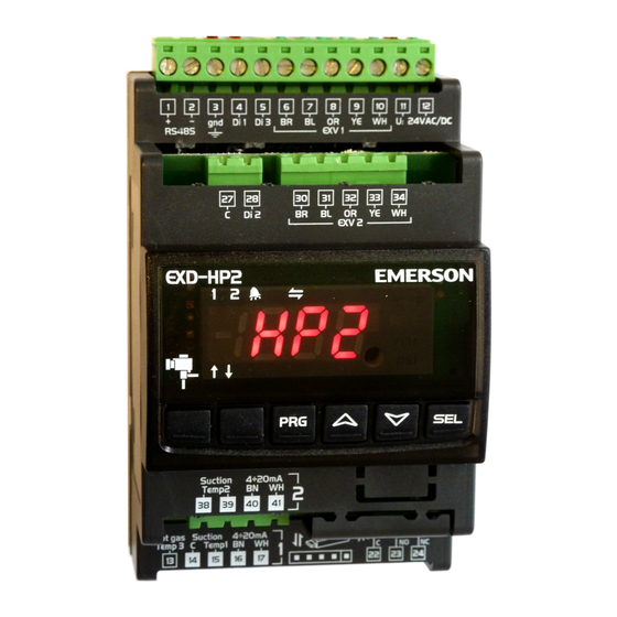
EXD-HP1/2 are stand-alone superheat and or economizer controllers. EXD-HP1 is
intended for operation of one EXM/EXL or EXN valve whereas EXD-HP2 is
designed for operation of two independent EXM/EXL or two EXN valves.
Note: It is possible to use only circuit 1 from EXD-HP2. In this case, the circuit
2 must be disabled (C2 parameter) and the sensors and the valve for the second
circuit are not needed.
ModBus communication is described in a Technical Bulletin and it is not covered
by this document.
T e c h n i c a l D a t a :
Power supply
24VAC/DC ±10%; 1A
Power consumption
EXD-HP1: 15VA
Plug-in connector
Removable screw terminals wire size 0.14...1.5 mm
Protection class
IP20
Digital Inputs
Potential free contacts (free from voltage)
Temperature sensors
ECP-P30
Pressure sensors
PT5N
Operating/surrounding temp.
0...+55°C
Output alarm relay
SPDT contact 24V AC 1 Amp inductive load;
24V AC/DC 4 Amp resistive load
Activated/energized: During normal operation (no alarm condition)
Deactivated/de-energized: During alarm condition or power supply is OFF
Coil: EXM-125/EXL-125 or EXN-125
Stepper motor output
Valves: EXM/EXL-... or EXN-...
Type of action
1B
Rated impulse voltage
0.5kV
Pollution Degree
2
Mounting:
For standard DIN rail
Marking
Dimensions (mm)
Warning -Flammable refrigerants:
EXD-HP1/2 has a potential ignition source and does not comply with ATEX
requirements. Installation only in non-explosive environment. For flammable
refrigerants only use valves and accessories approved for it!
S a f e t y i n s t r u c t i o n s :
• Read operating instructions thoroughly. Failure to comply can result in device
failure, system damage or personal injury.
• It is intended for use by persons having the appropriate knowledge and skill.
• Before installation or service disconnect all voltages from system and device.
• Do not operate system before all cable connections are completed.
• Do not apply voltage to the controller before completion of wiring.
• Entire electrical connections have to comply with local regulations.
• Inputs are not isolated, potential free contacts needed to be used.
• Disposal: Electrical and electronic waste must NOT be disposed of with other
commercial waste. Instead, it is the user responsibility to pass it to a designated
collection point for the safe recycling of Waste Electrical and Electronic
Equipment (WEEE directive 2019/19/EU). For further information, contact
your local environmental recycling center.
E l e c t r i c a l c o n n e c t i o n a n d w i r i n g :
• Refer to the electrical wiring diagram for electrical connections.
• Note: Keep controller and sensor wiring well separated from supply power
cables. Minimum recommended distance 30mm.
• EXM-125, EXL-125 or EXN-125 coils are supplied with fix cable and JST terminal
block at cable end. Cut the wires close to terminal block. Remove the wire
insulation approximately 7 mm at the end. It is recommended that the wires end to
Emerson Climate Technologies GmbH
Am Borsigturm 31 I 13507 Berlin I Germany
Operating instruction
EXD-HP1/2 Controller with ModBus
communication capability
EXD-HP2: 20VA
2
www.climate.emerson.com/en-gb
be equipped with core cable ends or metallic protective sleeve. When connecting
the wires of EXM/EXL or EXN, consider the color coding as follows:
EXD
Terminal
EXD-HP1
6
BR
7
BL
8
OR
9
YE
10
WH
EXD-HP2
30
BR
31
BL
32
OR
33
YE
34
WH
• The digital input DI1 (EXD-HP1) and DI1/D12 (EXD-HP1/2) are the
interfaces between EXD-HP1/2 and upper level system controller if the
Modbus communication has not been used. The external digital shall be
operated in function system's compressor/demand.
• If the output relays are not utilized, the user must ensure appropriate safety
precautions are in place to protect the system.
Operating condition
Compressor starts/run
Compressor stops
Note: Connecting any EXD-HP1/2 inputs to the supply voltage will
permanently damage the EXD-HP1/2.
W i r i n g b a s e b o a r d ( E X D - H P 1 / 2 ) :
Note:
• Base board is for function of superheat control or Economizer control.
• Alarm relay, dry contact. Relay coil is not energized during alarm condition or
power off.
• Hot gas discharge sensor input is mandatory only for economizer control function.
Warning: Use a class II category transformer for 24VAC power supply. Do
not ground the 24VAC lines. We recommend using individual transformers for
EXD-HP1/2 controller and for third party controllers to avoid possible
interference or grounding problems in the power supply.
EXD-HP12_OI_EN_DE_RU_1220_R06_865921.docx
EXM/L-125 wire color
EXN-125 wire color
Brown
Blue
Orange
Orange
Yellow
Yellow
White
White
Brown
Blue
Orange
Orange
Yellow
Yellow
White
White
Digital input status
closed (Start)
open (Stop)
Date: 17.12.2020
Red
Blue
Red
Blue
Advertisement

Related Manuals for Emerson EXD-HP1


Summary of Contents for Emerson EXD-HP1
- Page 1 Marking Dimensions (mm) Warning -Flammable refrigerants: EXD-HP1/2 has a potential ignition source and does not comply with ATEX requirements. Installation only in non-explosive environment. For flammable refrigerants only use valves and accessories approved for it! S a f e t y i n s t r u c t i o n s : •...
- Page 2 • Factory setting are applied • Apply supply voltage 24V to EXD-HP1/2 while the digital input (DI1/DI2) is Note: In standard mode the actual superheat is shown at the display. In case of liquid OFF(open). The valve will be driven to close position.
- Page 3 0 = Standard control coil heat exchanger *) EXN not permitted 1 = Slow control coil heat exchanger Warning -Flammable refrigerants: EXD-HP1/2 has a potential 2 = fixed PID ignition source and does not comply with ATEX requirements. Installation 3 = fast control plate heat exchanger (not for 1uE = 1) only in non-explosive environment.
- Page 4 Operating instruction EXD-HP1/2 Controller with ModBus communication capability C o n t r o l ( v a l v e ) s t a r t - u p b e h a v i o r : Factory...
- Page 5 EXD-HP1/2 sind autonome, universell einsetzbare Überhitzungs- und oder • Hinweis: Signalleitungen und Leitungen mit Netzspannung in getrennten Economiser-Regler. EXD-HP1 besitzt einen Regelkreis für ein Ventil der Baureihe Kabelschächten verlegen, Mindestabstand 30mm. EXM/EXL oder EXN, während EXD-HP2 Regelkreise für zwei Ventile EXM/EXL •...
- Page 6 Schutz des Verdichters und anderer Komponenten. Transformatoren für EXD-HP1/2 Regler und die Regler anderer Hersteller, • Wenn diese Hauptparameter eingestellt sind, ist der EXD-HP1/2 fertig zum Start. weil unter Umständen über die Erdleitungen Kurzschlüsse entstehen können. Alle anderen Parameter lassen sich bei Bedarf auch im laufenden Betrieb einstellen.
- Page 7 Warnung – Brennbare Kältemittel 0 = R22 1 = R134a 2 = R410A 3 = R32 4 = R407C EXD-HP1/2 hat eine potentielle Zündquelle und entspricht nicht den 5 = R290* 6 = R448A 7 = R449A 8 = R452A 9 = R454A* ATEX Bestimmungen.
- Page 8 Betriebsanleitung EXD-HP1/2 Überhitzungsregler mit ModBus Kommunikation M O P T a b e l l e ( ° C ) Code Parameter Beschreibung und Auswahl Werk Kältemittel Min. Max. Werk Kältemittel Min. Max. Werk MOP Betrieb Regelkreis 2 R452A 0 = aus...
- Page 9 EXD-HP1/2 являются автономными универсальными контроллерами перегрева • При проведении электрических подключений пользуйтесь схемой. и/или экономайзера. EXD-HP1 предназначен для работы с клапаном EXM/EXL • Внимание: Размещайте контроллер и провода датчиков на расстоянии или EXN, EXD-HP2 предназначен для работы с двумя независимыми...
- Page 10 • Убедитесь, что цифровой вход (DI1/DI2) разомкнут (0 В). Подайте случае впрыска жидкости или экономайзера там будет температура нагнетания. напряжение питания 24 В на EXD-HP1/2. Отобразите остальные данные контура 1 для EXD-HP1/2 или 2 для EXD-HP2: • • Параметры пароль (H5), тип функции (1uE), тип хладагента (1u0/2u0) и тип...
- Page 11 6 = R448A 7 = R449A 8 = R452A 9 = R454A* Предупреждение -Горючие хладагенты: EXD-HP1/2 являются 10 = R454B* 11 = R454C* 12 = R513A 13 = R452B* 14 = R1234ze* потенциальными источниками воспламенения и не соответствуют 15 = R1234yf * требованиям...
- Page 12 Руководство по эксплуатации EXD-HP1/2 Автономный контроллер перегрева / экономайзера П о в е д е н и е к л а п а н а с з а в о д с к и м и н а с т р о й к а м и п р и...
Need help?
Do you have a question about the EXD-HP1 and is the answer not in the manual?
Questions and answers