Emerson Bettis EHO Installation And Operation Manual
Double-acting, electro-hydraulic operated
Hide thumbs
Also See for Bettis EHO:
- Installation and operation manual (43 pages) ,
- Installation, operation and maintenance manual (46 pages)

Related Manuals for Emerson Bettis EHO


Summary of Contents for Emerson Bettis EHO
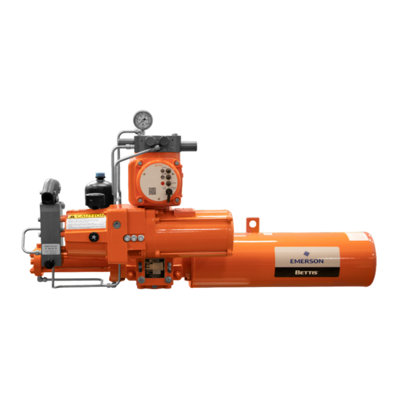
- Page 1 EHO.01.05.EN, Page 2 of 2, Rev. 0 Installation and Operation Manual Part Number: VA001-507-32, Rev. 1 Release: August 2016 Dimension Bettis EHO (Electro-Hydraulic Operated) ™ Double-Acting Actuator Double-Acting Actuator...
-
Page 2: Table Of Contents
Installation and Operation Manual Table of Contents Part Number: VA001-507-32, Rev. 1 August 2016 Table of Contents Section 1: Introduction Scope ......................1 General Information ................... 1 Safety Information ..................2 Abbreviation Definitions ................2 Section 2: Installation Preparation ....................4 Valve Preparation .................. - Page 3 Table of Contents Installation and Operation Manual August 2016 Part Number: VA001-507-32, Rev. 1 Section 6: Pushbutton Module (PBM) Selector Knob and Control Pushbuttons ........... 40 Section 7: Troubleshooting Section 8: Hazardous Area Classification and SIL Certification Section 9: Weights and Dimensions EHO Standard Double Acting ..............
-
Page 4: Section 1: Introduction
This manual is offered as a guide to be used along with locally approved and safe practices to install, operate, service and maintain the Bettis EHO Actuator. Carefully follow the instructions in this manual and make sure you install the actuator correctly and according to your requirements. -
Page 5: Safety Information
Alerts user of potential danger; failure to follow the warning notice could result in serious personal injury or death. CAUTION: Identifies precautions the user must take to avoid personal injury or equipment damage. NOTE: Highlights information critical to the user’s understanding of the Bettis EHO valve actuator installation or operation. Introduction... -
Page 6: Abbreviation Definitions
Installation and Operation Manual Section 1: Introduction Part Number: VA001-507-32, Rev. 1 August 2016 Abbreviation Definitions Abbreviations used in this manual and their definitions are listed in the table below: Table 1. Abbreviation Definitions Abbreviation Definition Installation Operation Manual Self-Contained Hydraulic Emergency Shutdown Fail-safe Spring-Return... -
Page 7: Section 2: Installation
For storage procedures exceeding one year, consult Bettis for further recommendations. As shipped from the factory, the Bettis EHO actuator is an inherently weatherproof unit, providing that all compartment covers and cable entry plugs remain intact. The actuator should be immediately stored in a clean, dry warehouse, free from vibration and rapid temperature changes, until it can be installed and energized. -
Page 8: Valve Preparation
Installation and Operation Manual Section 2: Installation Part Number: VA001-507-32, Rev. 1 August 2016 Valve Preparation 2.2.1 Remove Valve Gearing if so equipped. 2.2.2 If valve is equipped with stops, remove valve stem extension housing. Examine the valve stops to ensure no foreign material is present that would restrict normal travel of the valve. -
Page 9: Lifting The Eho Actuator
Part Number: VA001-507-32, Rev. 1 Lifting the EHO Actuator NOTE: All Bettis EHO G-Series Considerations When handling any EHO G-Series, be aware of tubing, accessories, hand pump, accumulators, Pushbutton module and control enclosures. Straps and chains can become entangled and cause damage to these components. Never use chains on the spring cartridge as it may warp and cause the actuator not to function correctly or may cause personal injury. - Page 10 Installation and Operation Manual Section 2: Installation Part Number: VA001-507-32, Rev. 1 August 2016 2.4.1.2 Horizontal Pipeline Horizontal Stem The small G-Series and all E-Series actuators mounting on a horizontal pipeline with a horizontal valve stem should be supported on the ends of the drive module.
- Page 11 Section 2: Installation Installation and Operation Manual August 2016 Part Number: VA001-507-32, Rev. 1 2.4.2.2 Horizontal Pipeline Vertical Stem The G3-Series actuator mounting on a horizontal pipeline with a horizontal valve stem should be supported on the ends of the drive module.
- Page 12 Installation and Operation Manual Section 2: Installation Part Number: VA001-507-32, Rev. 1 August 2016 2.4.3.2 Horizontal Pipeline Horizontal Stem The G4 – G7 Series actuators mounting on a horizontal pipeline with a vertical valve stem should be supported using the lift lugs attached to the drive module.
- Page 13 2.4.4 Mounting the Actuator in a Vertical Orientation on a Horizontal Stem When mounting an Bettis EHO Actuator in a vertical orientation, the Spring Module must be positioned up. The actuator may be supported by using two straps in the configuration shown in Figure 6.
-
Page 14: Installing The Eho Actuator On The Valve
Installation and Operation Manual Section 2: Installation Part Number: VA001-507-32, Rev. 1 August 2016 Installing the EHO Actuator on the Valve The actuator will be bolt-mounted directly to a bracket or adaptor that will be bolted securely to the mounting flange top works of the valve. 2.5.1 Check to see that the dimensions of the bracket or adaptor are suitable for use with the valve mounting flange and stem. -
Page 15: Hydraulic Fluid
Section 2: Installation Installation and Operation Manual August 2016 Part Number: VA001-507-32, Rev. 1 CAUTION: Always use the hand pump to move the actuator off the stop before attempting to turn the adjusting screw. 2.6.5 With the closed position stop set, use the hand pump to move the actuator to the other end of the stroke and check the stop position. -
Page 16: Accumulator (Optional)
2.8.1 Introduction The Bettis EHO Actuator may be equipped with an accumulator to enable manual operation of the actuator if there is a loss of electrical power. Accumulators always have the nitrogen pressure drained for shipping (except for Thermal Compensating Accumulator see 2.3.4). - Page 17 Section 2: Installation Installation and Operation Manual August 2016 Part Number: VA001-507-32, Rev. 1 NOTE: Recheck the pre-charge pressure after a time interval sufficient to insure the nitrogen pressure is equal to the ambient temperature (a minimum of 4 hours). Adjust the pre-charge pressure as required to conform to the Pressure versus Temperature graph.
- Page 18 Installation and Operation Manual Section 2: Installation Part Number: VA001-507-32, Rev. 1 August 2016 Table 3. Typical EHO Optional Accumulator System Part Number Part Name Reservoirs Accumulator Nitrogen Relief Valve 3-way Isolation Valve Isolation Valve (Accumulator Drain) Isolation Valve (Nitrogen Blow Down and Fill) Nitrogen Pressure Gauge Nitrogen Gauge Isolation Valve Speed Control...
- Page 19 Section 2: Installation Installation and Operation Manual August 2016 Part Number: VA001-507-32, Rev. 1 2.8.4 Nitrogen Pre-charge Maintenance Record Serial Number: _____________________________ Tag Number: _______________________________ Initial GA Chart Final Nitrogen Date Signed Pre-charge Requirement Pre-charge Leak Test Installation...
-
Page 20: Section 3: Electrical Connections
Installation and Operation Manual Section 3: Electrical Connections Part Number: VA001-507-32, Rev. 1 May 2016 Section 3: Electrical Connections Remove Separate Terminal Chamber (STC) Cover WARNING: Always verify electrical power is disconnected before removing the STC cover. 3.1.1 Remove cover with a strap wrench, drift, or pinch bar by rotating the cover counterclockwise. -
Page 21: Sealing Cable/Conduit Entries
Section 3: Electrical Connections Installation and Operation Manual May 2016 Part Number: VA001-507-32, Rev. 1 Sealing Cable/Conduit Entries Seal the cable and conduit entries in accordance with the National Electric Code or your country standard and applicable local codes. All conduit entries should be sealed against the site environment. -
Page 22: Separate Terminal Chamber (Stc) Connections
Installation and Operation Manual Section 3: Electrical Connections Part Number: VA001-507-32, Rev. 1 May 2016 Separate Terminal Chamber (STC) Connections 3.4.1 Connect the main power supply cables, including an Earth/Ground (refer to the job specific Wiring Diagram). 3.4.2 Use the barrier strip clamp screws to connect the control wiring (refer to the job specific Wiring Diagram). -
Page 23: Discrete Controlled Inputs Connection
Section 3: Electrical Connections Installation and Operation Manual May 2016 Part Number: VA001-507-32, Rev. 1 Discrete Controlled Inputs Connection The actuator can be controlled by discrete inputs: two-wire control, three-wire control, four-wire valve control. Connect the power for these discrete inputs as detailed in Figures 13 and 14. -
Page 24: Section 4: Set-Up/Start-Up Procedure
( ) correspond to components labeled on the schematic diagram. Information in (( )) is descriptive. When the Bettis EHO is delivered to the job site, it has been both pressure and function tested. The oil reservoir was filled to operation level when it shipped from factory. -
Page 25: Initial Check Of The Unit
NOTE: The components referenced below are referencing to schematic found in section 10.2. and is for illustration purposes only. When using this procedure refer to the Bettis EHO Actuator General Arrangement Drawing and Hydraulic Schematic for the unit being worked on. -
Page 26: Hand Pump
Hand Pump Isolation Valve (8) The components referenced below are referencing Schematic 4.4.1. and is for illustration purposes only. When using this procedure refer to the Bettis EHO Actuator General Arrangement Drawing and Hydraulic Schematic for the unit being worked on. - Page 27 NOTE: The components referenced below are referencing Schematic 4.4.2. and is for illustration purposes only. When using this procedure refer to the Bettis EHO Actuator General Arrangement Drawing and Hydraulic Schematic for the unit being worked on. 4.4.2.1 Check the Reservoir (I) to see the hydraulic is at the proper level.
-
Page 28: Hydraulic Test
NOTE: The components referenced below are referencing Schematic 4.4.2. and is for illustration purposes only. When using this procedure refer to the Bettis EHO Actuator General Arrangement Drawing and Hydraulic Schematic for the unit being worked on. 4.4.3.1 Select and slowly open the Accumulator override Isolation Valve (AD) for actuator open stroke and (AE) for actuator closing stroke. -
Page 29: Check Rotation
NOTE: The components referenced below are referencing to schematic found in section 10.2. and is for illustration purposes only. When using this procedure refer to the Bettis EHO Actuator General Arrangement Drawing and Hydraulic Schematic for the unit being worked on. -
Page 30: Limit Switch Adjustment
Installation and Operation Manual Section 4: Set-up/Start-up Procedure Part Number: VA001-507-32, Rev. 1 August 2016 4.6.5 While observing the inspection port, for motor rotation, push and release the OPEN/CLOSE PUSHBUTTON to Power Stroke the actuator and immediately push the STOP Pushbutton. Motor rotation should be counterclockwise when looking at the back of the motor. - Page 31 Section 4: Set-up/Start-up Procedure Installation and Operation Manual August 2016 Part Number: VA001-507-32, Rev. 1 WARNING: If the actuator is being installed in a hazardous area, use extreme care. This procedure requires the limit switch cover to be open while electrical power is connected to the unit. Follow these steps only when the atmosphere is free of explosive gases.
- Page 32 Installation and Operation Manual Section 4: Set-up/Start-up Procedure Part Number: VA001-507-32, Rev. 1 August 2016 4.7.3.6 With the LOCAL – OFF – REMOTE Switch set to LOCAL, push the OPEN PUSHBUTTON and allow the Actuator to travel to the Open position, rotated fully counterclockwise.
-
Page 33: Function Test
Double Acting Actuator without an ESD Solenoid Valve NOTE: The components referenced below are referencing Schematic 4.8.1. and is for illustration purposes only. When using this procedure refer to the Bettis EHO Actuator General Arrangement Drawing and Hydraulic Schematic for the unit being worked on. 4.8.1.1 Ensure both Hand Pump Selector Valves (M) are in the automatic open position. - Page 34 NOTE: The components referenced below are referencing Schematic 4.8.2. and is for illustration purposes only. When using this procedure refer to the Bettis EHO Actuator General Arrangement Drawing and Hydraulic Schematic for the unit being worked on. 4.8.2.1 Ensure both Hand Pump Selection Valves (M) are in the automatic open position.
-
Page 35: Other Options
Other options such as Partial Stroke Test may have been supplied with this order. Refer to supplemental start-up procedures supplied with these options for start-up and test. The functional test of the Electro-Hydraulic Actuator is now complete. The Bettis EHO Actuator is now operational and ready for service. Set-up/Start-up Procedure... -
Page 36: Section 5: Operation
Installation and Operation Manual Section 5: Operation Part Number: VA001-507-32, Rev. 1 August 2016 Section 5: Operation After initial start-up and commissioning procedures have been accomplished, the Bettis EHO Actuator provides a simple self-contained means of operation for a quarter turn valve. - Page 37 Section 5: Operation Installation and Operation Manual August 2016 Part Number: VA001-507-32, Rev. 1 NOTE: Item numbers correspond to attached schematic drawing 11794-S Bettis G-series Double Acting Actuator Electric Motor Hydraulic Pump Fluid Reservoir 3-Way Normally Closed Solenoid Valve for closing the actuator 3-Way Normally Closed Solenoid Valve for opening the actuator Adjustable Flow Controls.
- Page 38 Installation and Operation Manual Section 5: Operation Part Number: VA001-507-32, Rev. 1 August 2016 Figure 24 Main Components Double Acting with ESD Solenoid and Accumula- Pressure Gauge(Optional) Nitrogen Relief Valve(Optional) Isolation Valve(Optional) Hydraulic Accumulator With Nitrogen Blanket Charge(Optional) Accumulator Isolation Valve(Optional) Accumulator Isolation Valve(Optional) Pressure Switch Hydraulic Pressure Gauge...
- Page 39 Section 5: Operation Installation and Operation Manual August 2016 Part Number: VA001-507-32, Rev. 1 Hand Pump Selection Valves: These two valves are engaged to isolate the control system before using the hand pump. Note: Both selection valves are engaged at the same time when the hand pump is used to open or close the actuator.
-
Page 40: Functional Description
Installation and Operation Manual Section 5: Operation Part Number: VA001-507-32, Rev. 1 August 2016 Functional Description The following is a functional description of the Bettis Electro Hydraulic Actuator and a brief explanation of the main components. Throughout this explanation, numbers which appear in in [ ] correspond to components labeled on the wiring diagram. - Page 41 Section 5: Operation Installation and Operation Manual August 2016 Part Number: VA001-507-32, Rev. 1 5.4.2.3 ESD Operation ((Optional)) In an ESD application the ESD Solenoid (P) is constantly energized closed. This customer supplied signal is held as long as the signal is present. Upon loss of the signal to the ESD solenoid, the solenoid will de-energize and open allowing hydraulic supply fluid from the accumulator (E) to pass thru the ESD solenoid and to the closing port of the actuator (W).
-
Page 42: Section 6: Pushbutton Module (Pbm)
Installation and Operation Manual Section 6: Pushbutton Module (PBM) Part Number: VA001-507-32, Rev. 1 August 2016 Section 6: Pushbutton Module (PBM) The Pushbutton Module consists of the following as shown in Figure 18: • Two Pilot Lights: OPEN and CLOSE •... -
Page 43: Selector Knob And Control Pushbuttons
Section 6: Pushbutton Module (PBM) Installation and Operation Manual August 2016 Part Number: VA001-507-32, Rev. 1 Selector Knob and Control Pushbuttons The selector knob provides the choice of Local/Off/Remote operation. The control pushbuttons perform normal Open/Stop/Close function in the local control mode. -
Page 44: Section 7: Troubleshooting
Installation and Operation Manual Section 7: Troubleshooting Part Number: VA001-507-32, Rev. 1 August 2016 Section 7: Troubleshooting WARNING: To prevent personal injury, the actuator must be in spring-return, Fail-safe Position and all hydraulic pressure drained, including an optional accumulator, before opening any tube lines or attempting replacement operations below. -
Page 45: Section 8: Hazardous Area Classification And Sil Certification
Section 8: Hazardous Area Classification and SIL Certification Installation and Operation Manual August 2016 Part Number: VA001-507-32, Rev. 1 Section 8: Hazardous Area Classification and SIL Certification — CSA, Canadian Standard Association Certification Class I, Division I, Groups, C and D Group B configuration upon request —... -
Page 46: Section 9: Weights And Dimensions
Installation and Operation Manual Section 9: Weights and Dimensions Part Number: VA001-507-32, Rev. 1 August 2016 Product Data Sheet EHO.01.05.EN, Page 2 of 2, Rev. 0 March 2015 Section 9: Weights and Dimensions Dimension Double-Acting Actuator EHO Standard Double Acting &</,1'(5 &/ 32:(5 02'8/( +<'5$8/,&... -
Page 47: Section 10: Sample Wiring Diagram
Section 10: Sample Wiring Diagram Installation and Operation Manual August 2016 Part Number: VA001-507-32, Rev. 1 Section 10: Sample Wiring Diagram 10.1 2-Way Electric Powered By an Electro- Hydraulic Power Unit Figure 26 2-Way Electric Powered By an Electro-Hydraulic Power Unit Hydraulic Pressure Gauge Pressure Switch Pressure Transmitter(Optional) -
Page 48: 2-Way Electric With Emergency Shutdown Feature Powered By An Electro-Hydraulic Power Unit
Installation and Operation Manual Section 10: Sample Wiring Diagram Part Number: VA001-507-32, Rev. 1 August 2016 10.2 2-Way Electric With Emergency Shutdown Feature Powered By an Electro-Hydraulic Power Unit Figure 27 2-Way Electric with Emergency Shutdown Feature Powered By an Electro-Hydraulic Power Unit Pressure Gauge(Optional) Nitrogen Relief Valve(Optional) - Page 49 Qualified service personnel are available upon request for problems, which our customers do not wish to handle. If the requirement should arise please feel free to contact: Emerson Actuation Technologies, Inc. 19200 Northwest Freeway Houston, TX 77065 T +1 281 477 4100...
- Page 51 No.1 Lai Yuan Road The Emerson logo is a trademark and service mark of Emerson Wuqing Development Area EUROPE Electric Co. Bettis is a mark of the Emerson family of companies. Tianjin 301700 All other marks are property of their respective owners. P.R.China Berenyi u.
Need help?
Do you have a question about the Bettis EHO and is the answer not in the manual?
Questions and answers