Table of Contents
Advertisement
Quick Links
Instructions - Parts
™
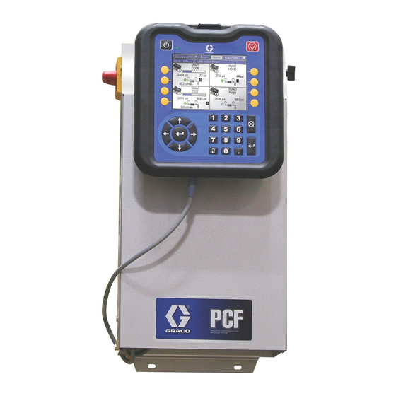
PCF
PrecisionSwirl
Precision Dispense System
Electronically-controlled fluid metering system that provides precise continuous flow of
up to four single-component sealants and adhesives through closed-loop technology.
Not for use in explosive atmospheres or hazardous locations.
For professional use only.
Important Safety Instructions
Read all warnings and instructions in this
manual. Save these instructions.
See page 4 for model information. See page 5 for
maximum working pressure and approvals.
IMPORTANT:
This manual does not apply to some PCF sys-
tems. See note on page 3 to verify this is the
correct manual for your PCF system.
with
™
Optional PrecisionSwirl Orbital
Dispenser (sold separately)
PCF Fluid Plate
3A2098S
EN
PCF Control Center
Advertisement
Table of Contents
Troubleshooting

Related Manuals for Graco PrecisionSwirl


Summary of Contents for Graco PrecisionSwirl
- Page 1 Read all warnings and instructions in this manual. Save these instructions. See page 4 for model information. See page 5 for maximum working pressure and approvals. Optional PrecisionSwirl Orbital Dispenser (sold separately) IMPORTANT: PCF Control Center This manual does not apply to some PCF sys- tems.
-
Page 2: Table Of Contents
Automation Control (Normal Operation) ..49 PrecisionSwirl Orbital Dispenser Assemblies . . . 8 Jobs ........49 Automation Gateway Assemblies . -
Page 3: Related Manuals
Graco Standard Warranty ....150 Graco Information ......150 ... -
Page 4: Models
Cartridge Coriolis Discrete Gateway systems do not include automation interface cables. The following Graco accessories are avail- able for wiring to the automation system. Installers should follow Appendix B - Discrete Gateway Module (DGM) Connection Details, page 121, for custom wiring. -
Page 5: Fluid Plate Kits
Models Fluid Plate Kits NOTE: The fluid plate kit numbers listed below include a CAN splitter. The fluid plate assembly included in each PFxxxx assembly does not include a CAN splitter. Includes: Fluid Used by Regula- Flow FCM Key Maximum Working Plate Kit Model Description... - Page 6 Models Includes: Fluid Used by Regula- Flow FCM Key Maximum Working Plate Kit Model Description Meter Token Pressure 6000 psi Cartridge Regulator, Glass Bead High 24V593 PF28xx 244734 24P688 16M102 (41 MPa, 414 bar) Resolution Flow Meter, 16 styles 6000 psi Cartridge Regulator, Glass Bead High 24V594 PF38xx...
-
Page 7: Control Panel Kits
Models Control Panel Kits NOTE: The control kit numbers listed below are replacement control enclosures with their voltage and automation interface listed. Automation Part No. Voltage Interface System Type DeviceNet 16K601 ACCESSORY SWIRL EtherNet/IP 16K602 ACCESSORY SWIRL PROFIBUS 16K603 ACCESSORY SWIRL PROFINET 16K604 ACCESSORY SWIRL... -
Page 8: Expansion Swirl Enclosure Assemblies
The following enclosures are ETL approved. Assemblies PFxxx2, and PFxxx3 are setup for one PrecisionSwirl Orbital Dispenser. If you wish to have additional swirl dispensers, order one expansion PrecisionSwirl assembly below for each. Systems with a DGM as the automation gateway can have up to two swirl dispensers total. Systems with a CGM as the automation gateway can have up to four swirl dispensers total. -
Page 9: Automation Gateway Assemblies
Models Automation Gateway Assemblies Each control center comes with one automation gateway assem- bly. The automation gateway module is either a Discrete Gate- way Module (DGM) or one of the Communications Gateway Modules (CGM).To order a replacement, see the following table. You will also need to order software upgrade token (16K743). -
Page 10: Integration Upgrade With Advanced Map
PCF, and do not plates). wish to change their Gateway setup from the old Gateway map 2. Allows for a complete integration of a Graco PCF to the new Gateway map. system, meaning an ADM is no longer necessary. 25C527 Advanced integration software kit. -
Page 11: Warnings
Warnings Warnings The following warnings are for the setup, use, grounding, maintenance, and repair of this equipment. The exclama- tion point symbol alerts you to a general warning and the hazard symbols refer to procedure-specific risks. When these symbols appear in the body of this manual, refer back to these Warnings. Product-specific hazard symbols and warnings not covered in this section may appear throughout the body of this manual where applicable. - Page 12 Warnings WARNING EQUIPMENT MISUSE HAZARD Misuse can cause death or serious injury. • Do not operate the unit when fatigued or under the influence of drugs or alcohol. • Do not exceed the maximum working pressure or temperature rating of the lowest rated system component.
-
Page 13: System Configurations
Drop Site . 1: Typical Ambient System Installation Key: *Control Center (User Interface) *Air Filter Assembly *Fluid Plate Assembly PrecisionSwirl Orbital Dispenser (Swirl Dispenser) Applicator/Dispense Valve M PrecisionSwirl Cable Sealer Automation Sealer Automation Control Cable Automation Interface Cable *CAN Cable... -
Page 14: Typical Installation - Multiple Fluid Plates, No Swirl Dispensers
System Configurations Typical Installation - Multiple Fluid Plates, No Swirl Dispensers Power In Air Supply Drop Site . 2: Typical Multiple Fluid Plate System Installation Key: *Control Center (User Interface) *CAN Cable *Fluid Plate Assembly G Fluid Supply System Applicator/Dispense Valve Fluid Supply Hose Sealer Automation Automation Controller... -
Page 15: Typical Installation - Multiple Fluid Plates, Multiple Swirl Dispensers
Sealer Automation Automation Interface Cable *CAN Cable G Fluid Supply System Fluid Supply Hose Automation Controller *Air Filter Assembly PrecisionSwirl Orbital Dispenser (Swirl Dispenser) M PrecisionSwirl Cable Expansion Swirl Enclosure O Sealer Automation Control Cable * Included Optional 3A2098S... -
Page 16: Overview
Anti-flutter simultaneously dispense from up to 10 dispense valves. • Body panel reinforcement • Profile wrapping PrecisionSwirl Orbital Dispenser • Cable filling (Swirl Dispenser), Sold Separately The swirl dispenser dispenses material in a circular pat- System Components tern at speeds from 6600 to 24000 rpm. A PCF fluid metering system can have up to four swirl dispensers. -
Page 17: Fluid Plate Assembly Overview
Overview Fluid Plate Assembly Overview The PCF fluid regulator is electrically controlled by the PCF fluid control module. Consistent material flow is assured by a closed-loop pressure or closed-loop flow Fluid Plate Components control design. The module responds to automa- tion-supplied signals to provide an accurate and consis- The fluid plate assembly in F . - Page 18 Overview Fluid Regulator Fluid Control Module (FCM) There are three fluid regulator options: • cartridge • ambient mastic • heated mastic All of the fluid regulator options use air pressure to con- trol fluid pressure, provide fast response to electronic commands, and ensure a precisely controlled, continu- Status Rotary...
-
Page 19: Control Center Assembly Overview
Overview Control Center Assembly Overview Front View Front View Side View 100-240 Vac Assembly Swirl Board Gateway Module Swirl Control CAN Splitter - To Fluid Plate - To ADM . 7: Control Center Components The control center includes the following components: •... - Page 20 Overview Advanced Display Module (ADM) TI12362a r_24E451_3B9900_1a . 8: Advanced Display Module Component Identification KEY: Callout Function Navigation Buttons Callout Function Navigate within a screen or to a new screen. Power On/Off Button Flat Panel Mount Enables/disables system. Mounts to control center bracket (optional). System Status Indicator LED Model Number Tag Displays system status.
- Page 21 Overview Automation Gateway Module See the following table for the appropriate rotary switch position for your automation gateway module. Gateway Part Number Rotary Switch Max Number of Model User Interface Description To Order Position Fluid Plates PFxx0x Discrete (DGM) 24B681 PFxx1x 15V759 ™...
- Page 22 Overview Swirl Control DGM One swirl control DGM is included in the integrated Swirl Rotary Switch control center, and in each expansion swirl enclosure. DGM Function Position Each Swirl control DGM controls one swirl orbiter. Swirl Control 1 Each swirl control DGM must have a unique rotary Swirl Control 2 switch position.
-
Page 23: Key Tokens
Overview Key Tokens NOTE: The key tokens for the ADM and FCM look alike but only work in one module or the other. If the key tokens for the ADM and FCM become mixed, locate the The ADM and FCM must each have a key token part number on each token then refer to the following installed in order to operate. -
Page 24: Installation
Installation Installation Before Installation 10. For systems with swirl dispensers, install each swirl dispenser onto outlet of a dispense valve. • Have all system and component documentation 11. Connect other fluid and air lines to additional system available during installation. components as instructed in their manuals. -
Page 25: Install Control Center
Installation Install Control Center Secure the control center with appropriate size bolts through the 0.27 in. (7 mm) diameter holes in the mount- ing tabs. See the following mounting dimensions. NOTE: This section applies to both the primary control center and the expansion Swirl enclosures. Table 4: Control Center Assembly Measurement Mount 10.50 in. - Page 26 Installation Electrical Connections This product must be grounded. In the event of an electrical short circuit, grounding reduces the risk of Ground electric shock by providing an escape wire for the electric current. • The control center must be electrically connected to a true earth ground;...
-
Page 27: Install Fluid Plate Assemblies
• Be sure all accessories are adequately sized and pressure-rated to meet the system's requirements. • Use only the Graco PCF fluid plate assembly with . 15: Fluid Plate Assembly Dimensions the Graco PCF control center. Mount Assembly 1. Select a location for the fluid plate assembly. Keep the following in mind: •... - Page 28 Installation Mount Coriolis Flow Meter Horizontal Installation NOTE: A Coriolis flow meter only comes with PFxCxx The horizontal installation is the recommended installa- tion. assemblies. NOTICE If the medium might contain solid particles, mount the See Fluid Plate Assembly Technical Data on page meter as shown in position A, in all other cases as 149 for the weight of your meter.
- Page 29 Installation Critical Installations 2. Install bulkhead fitting (included in the kit) into the empty hole on the fluid plate. The meters must be mounted at the highest point of the tubing (A), if gas bubbles are to be expected, or at the lowest point (B), if solid particles are to be expected, as GCA Cable in both cases also the right orientation might not help.
- Page 30 Installation Custom Breakout Cable If desired, the following connector pinout information may be used to build a custom breakout cable: Pinout of FCM Port 1 Pin 1: Dispense Solenoid 4 Pin 2: Dispense Solenoid 2 Pin 3: Voltage - (common for all solenoids) Pin 4: Dispense Solenoid 1 Pin 5: Dispense Solenoid 3 Dispense solenoid outputs are 24 Vdc.
- Page 31 Installation Ground Solvent Pails Used When Flushing Follow local code. Use only conductive metal pails, placed on a grounded surface. Do not place the pail on a non-conductive surface, such as paper or cardboard, This product must be grounded. In the event of an which interrupts grounding continuity.
-
Page 32: Install Cable Assemblies
Installation Install Cable Assemblies NOTE: To prevent system errors, only connect cables with the power off. NOTE: See F . 20 on page 33. 1. For systems with more than one swirl dispenser: Use a CAN cable to connect the control center to one swirl expansion enclosure. - Page 33 Installation ti30855a Multiple Fluid Plate and Multiple Swirl System shown . 20: Cable Installation Diagram 3A2098S...
-
Page 34: Install Gateway Module Interface
CGM Status LED Signals 4. Retrieve the appropriate fieldbus configuration file Signal Description for the fieldbus being used from www.graco.com. Green on System is powered up 5. Install the configuration file on the automation Yellow Internal communication in progress controller (fieldbus master). - Page 35 49, for details on controlling the PCF system through the Gateway module. Connect D-Sub Cable The DGM provides all I/O through the D-Sub cable. Graco offers two options for connecting a D-Sub cable to the D-Sub connector (CG). Both options are accessories and must be ordered separately. •...
-
Page 36: System Setup
System Setup System Setup Overview Configure System The PCF system compensates for temperature, flow, or Define the number of installed fluid plates (called pressure fluctuations. However, if there is a hardware “Dispenser” on this screen) and number of installed swirl change on the supply system or the dispense material is dispensers. -
Page 37: Configure Control Settings
System Setup Configure Control Settings 7. Press to move to the Job End Delay field. Enter Set the controls for the dispense source, how dispense the desired delay time (in seconds). Press commands are sent, and job settings. enter the value. 1. -
Page 38: Configure Mode Settings
System Setup Configure Mode Settings 5. Press to move to the Bead Scale field. Enter a Set valve commands, including the dispense mode scale value between 50% and 150%. Press (pressure, bead, shot, or full open) and flow rate or enter the value. -
Page 39: Configure Flow Meter Settings
System Setup Configure Flow Meter Settings 3. Press to open the Meter Type drop-down list, and select the meter type used by the system. The accuracy of the PCF volume reporting depends on Select Volume for volumetric flow meters or Mass precise adjustment of the K-factor(s). -
Page 40: Adjust Pressure Sensors
System Setup Adjust Pressure Sensors Configure Errors Set pressure offsets and pressure limits. Set the error type (alarm, deviation, or none) that will be issued if the pressure, flow rate, volume, or computed NOTE: Inlet sensor settings will be grayed out on this target goes outside the tolerance settings of the active screen for systems with heated fluid plates. -
Page 41: Setup Maintenance Schedule/Parameters
System Setup Setup Maintenance To reset a totalizer value: Schedule/Parameters 1. Follow Steps 1-3 of To set limits: to make changes in Fluid Plate x, screen 7 (Maintenance Advisory Limits). Set the volume (or hours) limit that will trigger a maintenance advisory for the fluid supply, Voltage to Pressure (V/P) Transducer, fluid regulator, flow meter, 2. -
Page 42: Configure Swirl Settings
System Setup Configure Swirl Settings NOTE: This applies only to systems with swirl dispensers. Set the individual Swirl settings for each installed Swirl. . 31 Configure Gateway Settings Gateway settings differ for each system. See Automation Gateway Setup Screens, page 107, for guidelines on configuring each type of Gateway interface. -
Page 43: On/Off Delays
System Setup On/Off Delays . 32 and Table 6: Delay On/Off Timing show delay ON and OFF timing. The PCF fluid regulator can physically respond faster Table 6: Delay On/Off Timing than the dispense device and its solenoid. As a result, A Regulator ON The user sets the fluid the fluid regulator can supply material to the dispense... -
Page 44: Operation
Operation Operation Load Material Pressure control may degrade at low output pressures. It is not recommended to dispense at outlet pressures less than 500 psi (3.4 MPa, 34 bar). Before using the system material must be loaded into the supply system. Startup 1. -
Page 45: Maintenance Mode Operation
Operation Maintenance Mode Operation Follow steps in the supply system manual to set the inlet pressure. Swirl Fluid Plate NOTICE Maintenance Screen Maintenance Screen Inlet pressure beyond the recommended range above will cause accelerated wear on the regulating valve and the pump feed system. Feed System Pressure Drop During material flow, the regulator inlet pressure decreases. - Page 46 Operation Dispense from Each Valve Verify Flow Meter Calibration Dispense from each valve that will be used in normal Most sealant and adhesive materials are compressible. operation to confirm that the entire system is installed Since the flow meter measures the material under high correctly and is capable of delivering desired results.
- Page 47 Operation 3. Manually dispense material into the beaker. Hold the 6. Optional: To fine tune the step response in pressure beaker so that the stream of material is submerged mode, gradually increase the Kd value. in the captured material to minimize air entrapment NOTE: Increasing Kd (pressure only) is typically not nec- in the container.
- Page 48 Operation 4. Press to move to the target fields. Enter the 2. Press to enter maintenance screen. target pressure, flow rate, or volume (dependent on control mode) and press to save. 5. Press to move to the valve check boxes. Press to select the desired valves.
-
Page 49: Automation Control (Normal Operation)
Operation Automation Control (Normal Actual (Measured) Volume - The amount of material measured by the flow meter during a job. Operation) Requested Volume - The amount of material that the During automation control (normal operation), the automation tries to dispense during a job. In Bead system can dispense or change dispense parameters mode, the requested volume is calculated as the when it receives a command from the automation unit. -
Page 50: Styles
Operation Styles 3. Enter the style number in the Style field. 4. Enter Style Name: The PCF system has the ability to handle up to 256 styles, depending on the selected option. a. Press while in the Style Name field to NOTE: The number of available styles depends on the display the Keyboard screen. -
Page 51: Precharge Modes
Operation Precharge Modes Gateway NOTE: Gateway precharge mode is only available for NOTE: See the diagram on the following page. systems containing CGMs. Static Precharge Mode When “Gateway” precharge mode is selected, the outlet pressure will be set according to the current pressure/flow command using the scaling set for Display dispense valve(s) selected through the gateway... - Page 52 Operation Closed Precharge Scaling Value Dispense Application Direction Dispense Application Direction Dispense Application Direction Value Too Low Ideal Value Value Too High -Controls outlet pressure based on desired command while valves are closed. -Ideal value is typically less than 100% due to the minimal pressure losses within the system when fluid is not flowing.
-
Page 53: Typical Job Cycle
Operation Typical Job Cycle 7. PCF sets the following signals based on the results of the job. In order for the system to run it must be in the active • Dispenser (Fluid Plate) No Alarm state (status LED next to on the ADM is green). - Page 54 Operation Typical Job Cycle Chart NOTE: Swirl can be turned on at any point inside of or outside of a job. Allow time for the swirl to reach desired RPM. If possible, verify Swirl speed through the automation interface prior to opening the dispense valve.
- Page 55 Operation Control Charts Purge Using Style 0 Automation Inputs (PCF Outputs) Dispense Ready Dispenser (Fluid Plate) No Alarm Dispenser (Fluid Plate) No Error Dispense In Process Purge In Process Volume OK Automation Outputs (PCF Inputs) Style Bits Style Strobe Dispense Valve X On Dispense Complete PCF State Dispense Valve X Open...
- Page 56 Operation Control Charts (continued) Remote Start Automation Inputs (PCF Outputs) Dispenser (Fluid Plate) Ready Dispenser (Fluid Plate) No Alarm Dispenser (Fluid Plate) No Error Dispenser (Fluid Plate) Remote Start/Purge in Process Automation Outputs (PCF Inputs) Remote Start/Purge Error Reset Automation Inputs (PCF Outputs) Dispenser (Fluid Plate) No Alarm / Dispenser (Fluid Plate) No Error Automation Outputs (PCF Inputs) Error Reset...
- Page 57 Operation Control Charts (continued) Precharge* - Display Mode Automation Inputs (PCF Outputs) Dispense Ready Dispenser (Fluid Plate) No Alarm Dispenser (Fluid Plate) No Error Dispense In Process Volume OK Automation Outputs (PCF Inputs) Style Bits Style Strobe Dispense Valve X On Dispense Complete PCF State Regulator Active...
- Page 58 Operation Control Charts (continued) Precharge* - Valve 1 Mode Automation Inputs (PCF Outputs) Dispense Ready Dispenser (Fluid Plate) No Alarm Dispenser (Fluid Plate) No Error Dispense In Process Volume OK Automation Outputs (PCF Inputs) Style Bits Style Strobe Command Signal Valid† Dispense Valve X On Dispense Complete PCF State...
- Page 59 Operation Control Charts (continued) Trigger Using Command Cable Automation Inputs (PCF Outputs) Dispense In Process Command Cable Dispense Trigger PCF State Regulator Active (Precharge = 0) Dispense Valve X Open* Dispense Valve X Open determined by Enable Valves check boxes on Fluid Plate x, screen 1(Control Settings). Trigger Using Gateway Automation Inputs (PCF Outputs) Dispense In Process...
- Page 60 Operation Control Charts (continued) Enable Swirl Dispenser Automation Inputs (PCF Outputs) Dispenser (Fluid Plate) Ready Swirl X Actual Speed - RPM (32 bits) Actual Speed Value Valid Automation Outputs (PCF Gateway Inputs) Swirl X Speed Command (12 bits) Command Value Set Swirl X Enable PCF State Swirl X On...
-
Page 61: Pressure Relief Procedure
Pressure Relief Procedure Pressure Relief Procedure b. Continue actuating the plunger until all pressure is purged from the system between the needle and the dispense valves attached to this fluid The equipment stays pressurized until pressure is plate before proceeding to the next step. manually relieved. -
Page 62: Shutdown
Shutdown Shutdown 1. Press the Stop button (BC). TI12362a . 40: ADM - Stop Button 2. Shut off the material supply to the fluid plate/meter. 3. Follow the Pressure Relief Procedure on page 61. 4. Turn off the PCF system's compressed air supply. 5. -
Page 63: Usb Data
The 8-digit numeric folder name matches the 8-digit • Actual dispensed volume (in the units shown in ADM serial number. When downloading from multiple the volume units column) ADMs, there will be one sub-folder in the GRACO folder • Volume units for each ADM. •... -
Page 64: System Configuration Settings File
USB Data System Configuration Settings Custom Language File File The custom language file name is DISPTEXT.TXT and is stored in the DOWNLOAD folder. The system configuration settings file name is SETTINGS.TXT and is stored in the DOWNLOAD A custom language file automatically downloads each folder. -
Page 65: Download Procedure
5. Open system folder. If working with more than one system, there will be more than one folder within the 6. Open Graco folder. Graco folder. Each folder is labeled with the 7. Open system folder. If downloading data from more corresponding serial number of the ADM. (The than one system, there will be more than one folder. -
Page 66: Troubleshooting
Troubleshooting Troubleshooting NOTE: Check all possible solutions in the chart below before you disassemble the system. Troubleshooting for individual fluid regulators and flow meters is also discussed in their separate manuals; refer to Related Manuals on page 3. Also refer to Event and Error Codes and Troubleshooting, page 71, for detailed information on how error codes are communicated. -
Page 67: Flow Meter
Troubleshooting Flow Meter Problem Cause Solution No flow measurement Flow meter pick-up sensor loose Tighten flow meter pick-up sensor Flow too low Verify flow rate is above minimum for the installed flow meter Loose wiring Verify connection from flow meter to Damaged flow meter pick-up sensor Replace pick-up sensor False measurement... -
Page 68: Dispense Valves
Troubleshooting Dispense Valves Problem Cause Solution Valve not opening Air not getting to the open port Verify air pressure to solenoid No “Valve On” signal from automa- Check input from automation unit tion unit Valve not shutting off Air not getting to the close port Verify air pressure to solenoid (except AutoPlus valve) Verify solenoid operation... -
Page 69: Gateway Module
PCF Gateway configuration settings. Incorrect data Incorrect fieldbus configu- Download PCF fieldbus configuration file from ration file installed on www.graco.com, and install on automation controller (fieldbus automation controller master). (fieldbus master) Incorrect map installed on Confirm correct PCF data map is installed on PCF Gateway. -
Page 70: Errors
Errors Errors View Errors Diagnose Errors When an error occurs, an error pop-up is displayed that See Event and Error Codes and Troubleshooting on takes up the entire screen until the error is page 71 for error codes, possible causes, and solutions. acknowledged by pressing . -
Page 71: Event And Error Codes And Troubleshooting
Error codes in the following table are sorted by gateway error number, then by event code. NOTE: The following error list is available in the PCF Integration package at www.graco.com. System Events and Errors Event... - Page 72 Errors Event Gateway Event Code Error No. Event Name Description Event Type Cause Solution Control Center Events and Errors EBUX Download to Download to the USB is Advisory No action necessary USB Complete complete (self-clearing) WSU0 USB configura- USB configuration error Advisory USB configuration Reinstall system soft- tion error...
- Page 73 Errors Event Gateway Event Code Error No. Event Name Description Event Type Cause Solution Fluid Plate Events and Errors B30_ High Material Material dispensed Alarm or PCF regulator is not Check regulator and B40_ during last dispense Deviation regulating correctly repair if necessary cycle was above (user select-...
- Page 74 Errors Event Gateway Event Code Error No. Event Name Description Event Type Cause Solution Fluid Plate Events and Errors WED_ V/P Error Voltage to Pressure Alarm Problem detected with Verify outlet pressure Transducer error transducer is installed and/or connected cor- rectly Replace if necessary WJ1_...
- Page 75 Errors Event Gateway Event Code Error No. Event Name Description Event Type Cause Solution Fluid Plate Events and Errors WFD_ Flow Meter Operating mode Alarm or Selected valve mode Check valve mode set- WFG_ Required requires flow meter. Advisory settings require flow tings Advisory is issued if (self-clearing)
- Page 76 Errors Event Gateway Event Code Error No. Event Name Description Event Type Cause Solution Fluid Plate Events and Errors P3C_ High Pressure Measured outlet pres- Alarm or Incorrect limit set Verify limit is set cor- P4C_ sure greater than Deviation rectly desired outlet pressure (user select-...
- Page 77 Errors Event Gateway Event Code Error No. Event Name Description Event Type Cause Solution Fluid Plate Events and Errors MED_ Maintenance Maintenance due for Advisory Totalizer exceeded Service component Due - V/P Voltage to Pressure limit setting If necessary, reset Transducer totalizer MCD_...
- Page 78 Errors Event Gateway Event Code Error No. Event Name Description Event Type Cause Solution Fluid Plate Events and Errors CR3_ Valve 3 Swirl Fluid plate communica- Alarm The fluid plate lost Restore communica- Communication tion error with swirl communication with tions.
- Page 79 Errors Swirl Events and Errors Event Gateway Event Code Error No. Event Name Description Event Type Cause Solution Swirl Events and Errors CBR_ Swirl Communi- Swirl communication Alarm The ADM lost commu- Restore communica- cation Error error with ADM nication with the Swirl tions Control DGM CDR_...
-
Page 80: Maintenance
Maintenance Maintenance Prior to performing any maintenance procedures, follow the Pressure Relief Procedure on page 61. Maintenance Schedule The following tables list the recommended maintenance procedures and frequencies to operate the equipment safely. The maintenance is divided between mechanical and electrical tasks. Maintenance must be performed by trained personnel per this schedule to assure safety and reliability of the equipment. -
Page 81: Advanced Display Module (Adm)
Maintenance Advanced Display Module Upgrade Gateway Module (ADM) Software (16K743) NOTE: The Gateway module connection to the system Upgrade Software (16K743) is temporarily disabled during the use of upgrade tokens. The following instructions apply to all Gateway NOTE: Back up the custom language file (if installed) modules. -
Page 82: Upgrade Gateway Module Fieldbus Map
Maintenance Upgrade Gateway Module 4. Press and hold the push button for three seconds and then release. The red indicator light (CK) will Fieldbus Map (16N601 or flash twice, pause, and then once after the data 17P799) map is uploaded. NOTE: The fieldbus connection is temporarily disabled during the use of a map token. -
Page 83: Upgrade Fluid Control Module (Fcm) Software
Maintenance Upgrade Fluid Control Module 7. Reinstall blue key token, and replace access cover. (FCM) Software (16K743) Air Filter Maintenance NOTE: The FCM connection is temporarily disabled during the use of the upgrade token. To prevent filter element damage, replace air filter every two years or when pressure drop becomes 100 kPa 1. -
Page 84: Repair
Repair Repair Fluid Plate Assembly NOTE: The Coriolis flow meter is not field repairable. Remove Flow Meter from Mounting Plate 1. Prepare Fluid Plate Assembly for Repair, page This section describes how to remove and replace com- 2. Disconnect the flow meter cable (131) from the flow ponents on the fluid plate assembly. - Page 85 Repair Install Flow Meter on Mounting Plate 4. Remove the dispense valve solenoid (132) and replace it with a new solenoid. NOTE: The Coriolis flow meter does not mount to the fluid plate. 1. Rest the flow meter (129) and bracket (124) on the fluid plate while threading the swivel fitting (109) onto the regulator material inlet.
- Page 86 Repair 5. Secure the new V/P transducer to the bracket with Replace Fluid Control Module Base screws. 1. Prepare Fluid Plate Assembly for Repair, page 6. Reconnect the FCM cable and both air tubes. 2. Remove the FCM (103); follow Replace Fluid Replace Fluid Control Module Control Module.
- Page 87 Repair Replace Transducer O-Rings 1. Prepare Fluid Plate Assembly for Repair, page 2. Remove the fluid outlet pressure sensor (117) from the regulator (108). r_pf0000_313377_16a . 58 3. Press the transducer (CG) out of the retainer nut (CH). 4. Remove the faulty o-ring (120) and replace with new.
- Page 88 Repair Repair Fluid Regulator NOTE: The retaining nut (CC) often loosens when removing the cartridge assembly from the base housing. For complete cartridge fluid regulator repair refer to Be sure to re-torque as described in step 4. instruction manual 308647. For complete mastic fluid regulator repair refer to instruction manual 307517.
- Page 89 Repair Replace Amplifier Adjust Display Settings 3. With the system in setup mode, navigate to the (Heated fluid plates only) Advanced screens. 1. Prepare Fluid Plate Assembly for Repair, page 4. Press to scroll to Advanced screen 2. 2. Disconnect pressure sensor cable (117) and power output cable.
- Page 90 Repair Adjust Amplifier Settings 17. Use the data from the certificate of calibration for the pressure sensor (included with PCF 12. Remove cover from amplifier (116). See Replace documentation or the replacement pressure sensor) Amplifier, page 89. to calculate the Shunt Calibration Pressure using the following formula: 13.
-
Page 91: Control Center Assembly
Repair Control Center Assembly Replace Gateway Module Base 1. Prepare Control Center for Repair, page 91. 2. Remove the Gateway module (5); follow Replace Gateway Module. (Leave automation communications cable (AE) attached to Gateway module.) Prepare Control Center for Repair 1. - Page 92 Repair Replace Swirl Board 16K570: Replace Advanced Display Module 1. Prepare Control Center for Repair, page 91. 1. Prepare Control Center for Repair, page 91. 2. Remove screw (a) from swirl board cover. Open 2. Disconnect the CAN cable (18) from the ADM (2). swirl board cover.
- Page 93 Repair Replace DIN Rail Assembly Replace Advanced Display Module Bracket 1. Prepare Control Center for Repair, page 91. 1. Prepare Control Center for Repair, page 91. 2. Remove the ADM (2); follow Replace Advanced 2. Remove both screws (22) and washers (28) from Display Module.
- Page 94 Repair 6. Remove the din rail, filter, and rocker switch (snaps into place). Replace with new components. Secure din rail and filter to the rear control center assembly. cover (1) using the four screws (40). Snap rocker/rotary switch into position. r_pf0000_313377_10a .
-
Page 95: Parts
Parts Parts Control Centers Software Upgrade Tokens Refer to the Software Upgrade Tokens table on page Control Center Key Token Part Numbers See Key Tokens on page 23 for more information about key tokens. Part Description ADM Key Token, Standard PCF 16M217 Gateway Module Part Numbers User... -
Page 96: Parts
Parts Control Center and Expansion Swirl Enclosure Parts 6,10 3,4,12,16 5 or 43 24 VDC units only: 15,36 100-240 VAC units only: 6,36 23,27 Line/ Neutral/ Ground/ Brown Blue Green Add ferrite (36) to cable. Locate Control centers only. Not included as close to cable connector as in expansion swirl enclosures. - Page 97 Parts Control Center Assembly Parts Ref. Part Description Ref. Part Description LABEL COVER, rear 110637 SCREW, mach, pan hd 2 24E451 DISPLAY, with USB 43 24B681 MODULE, DGM 3 289697 BASE, cube GUARD, edging 4 277674 ENCLOSURE, cube door 16K570 BOARD, circuit, swirl 5...
-
Page 98: Fluid Plate Assembly Parts
Parts Fluid Plate Assembly Parts 117, 120 135, 136 3A2098S... - Page 99 Parts Fluid Plate Assembly Parts (continued) 3A2098S...
- Page 100 Parts Fluid Plate Assembly Parts (continued) ti19262a Fluid Plate 24B962 Shown 105, 116 140, 141, 150 3A2098S...
- Page 101 Parts Fluid Plate Assembly Parts (continued) Mass Flow Meter Shown 3A2098S...
- Page 102 Parts Fluid Plate Assembly Parts Ref. Part Description Qty. 194337 WIRE, grounding, door Ref. Part Description Qty. 153 186620 LABEL, ground PLATE, fluid 155 SUPPRESSOR, box snap, fer- 289697 BASE, cube rite 103 289696 FCM, cube 122610 ELBOW 277674 ENCLOSURE, cube door 159...
- Page 103 Parts Parts Varying by Assembly The following table lists the varying part numbers by fluid plate assembly, and the quantity for each assembly. Fluid Plate Assemblies Heated Mastic Regulator Cartridge Mastic with Heated Cartridge Regulator Cartridge Regulator Mastic Heated Mastic Regulator with High Regulator...
-
Page 104: Appendix A - Advanced Display Module (Adm)
Appendix A - Advanced Display Module (ADM) Appendix A - Advanced Display Module (ADM) Display Details A PCF can operate without an ADM if it is fully integrated and all signals come from the automation controller. Power Up Screen The following screen appears when the ADM is pow- Display Overview ered up. - Page 105 Appendix A - Advanced Display Module (ADM) Soft Keys System Mode There are five modes: Active, Job in Cycle, Display Icons next to the soft keys indicate which mode or action Control, Swirl Setup, and System Off. The current is associated with each soft key. Soft keys that do not system mode is displayed at the left of the menu bar.
-
Page 106: Setup Mode
Appendix A - Advanced Display Module (ADM) Setup Mode Advanced Setup Screen 2 This screen enables users to set the units of measure Setup mode screens are divided into five sections: for maintenance volume, maintenance mass, pressure, System setup, Advanced setup, Gateway setup, Fluid and flow rate. - Page 107 Appendix A - Advanced Display Module (ADM) Automation Gateway Setup Screens Gateway Setup Screen 1 - EtherNet/IP This screen enables users to set the IP address, subnet There are up to three automation Gateway Setup mask, Gateway, DNS 1, DNS 2, and if a DHCP is used. screens (depending on fieldbus), which enable users to set or change information regarding the automation Gateway module used on the PCF system.
- Page 108 Appendix A - Advanced Display Module (ADM) Gateway Setup Screen 1 - PROFIBUS Gateway Setup Screen 2 - PROFINET This screen enables users to set the device address, This screen enables users to set the device address, install date, location tag, function tag, and system install date, location tag, function tag, and system description.
- Page 109 Appendix A - Advanced Display Module (ADM) Discrete Gateway (Automation) Setup Digital Command Logic Table (Single Fluid Plate Systems) Screen NOTE: The Discrete Gateway Setup screen is not Digital Digital available if an automation Discrete Gateway Module Command Command Resulting Digital (DGM) is not attached to the system.
- Page 110 Appendix A - Advanced Display Module (ADM) Digital Command Logic Table (2-Fluid Plate Systems) Digital Digital Command Command Resulting Digital Input 1 Input 2 Command Selection Fluid Plate 1, Setting #1 Fluid Plate 1, High Setting #2 Fluid Plate 2, Setting #1 Fluid Plate 2, High...
- Page 111 Appendix A - Advanced Display Module (ADM) Fluid Plate Setup Screens There are nine fluid plate setup screens, which enable NOTE: Run mode bead adjust allows a user to quickly users to: adjust flow rate or pressure from the run screen. •...
- Page 112 Appendix A - Advanced Display Module (ADM) Fluid Plate x, Screen 3 (Delay Settings) Fluid Plate x, Screen 5 (Pressure Sensors) This screen enables users to set on and off delays (in NOTE: Inlet sensor settings will be grayed out on this screen for systems with heated fluid plates.
- Page 113 Appendix A - Advanced Display Module (ADM) Fluid Plate x, Screen 6 (Error Type) Fluid Plate x, Screen 7 (Maintenance Advisory Limits) This screen enables users to set the error type (none, alarm, or deviation) that will be issued if the pressure, This screen enables users to set volume (or hours) limit flow rate, volume, or computed target goes outside the that will trigger a maintenance advisory for the air sup-...
- Page 114 Appendix A - Advanced Display Module (ADM) Fluid Plate x, Screen 8 (Style) Fluid Plate x, Screen 9 (Swirl Association) This screen enables users to set up to 256 styles, This screen enables users to set the swirl to fluid plate association.
- Page 115 Appendix A - Advanced Display Module (ADM) Swirl Setup Screen This screen enables users to: • Set the Speed Command Source to Display or Gateway. If it is set to Display, users can set the fixed speed • Set the Run Mode Speed Adjust to Enable or Disable •...
-
Page 116: Run Mode
Appendix A - Advanced Display Module (ADM) Run Mode Run mode screens are divided into six sections: home, Swirl Home Screen fluid plates, swirls, events, errors, and jobs. While in NOTE: This screen only appears if more than one Swirl Dispenser is installed. - Page 117 Appendix A - Advanced Display Module (ADM) Fluid Plate x, Screen 1 The PCF system has two operating modes: This screen displays the current dispense control mode • Dispense mode – enables the module to begin used, the current pressure, and the current style being dispensing when it receives a command from the dispensed.
- Page 118 Appendix A - Advanced Display Module (ADM) Maintenance Mode Dispense Control Modes The PCF system has four fluid dispensing control Press from Fluid Plate x, screen 1 (Control Center) modes. to enter maintenance mode. Maintenance mode enables users to change the control mode, volume to be •...
- Page 119 Appendix A - Advanced Display Module (ADM) Fluid Plate x, Screen 2 (Control Center) Fluid Plate x, Screen 3 (Maintenance Totalizers) This screen enables users to view the maintenance NOTE: Users must be out of maintenance mode in Fluid totalizers for each system component and the limits set Plate x, screen 1 in order to scroll to this screen.
- Page 120 Appendix A - Advanced Display Module (ADM) Swirl X Screen Event Report Screens There is one Swirl X screen for each installed swirl The event report screens display a chronological list of dispenser. This screen displays the following items: system events. These screens display the last 200 events.
-
Page 121: Appendix B - Discrete Gateway Module (Dgm) Connection Details
Appendix B - Discrete Gateway Module (DGM) Connection Details Appendix B - Discrete Gateway Module (DGM) Connection Details D-Sub Cable 123793 The D-sub cable 123793 is only compatible with single fluid plate systems. Systems with 2 fluid plates must use cable 123792 and breakout board 123783. -
Page 122: D-Sub Cable 123792 And Breakout Board 123783
Appendix B - Discrete Gateway Module (DGM) Connection Details D-Sub Cable 123792 and Breakout Board 123783 The cable length of the interface cable assembly 123792 is 50 ft (15.2 m). The following table identifies the pin assignments for the 78-pin breakout board. NOTE: See Appendix D - I/O Signal Descriptions on page 146. - Page 123 Appendix B - Discrete Gateway Module (DGM) Connection Details D-Sub Pin No. Description Pin Type Voltage (Vdc) Style Strobe Fluid Plate 1 Digital In 0-30 Dispense Complete Digital In 0-30 Error Reset Digital In 0-30 Remote Start/Purge Digital In 0-30 60 -67...
- Page 124 Appendix B - Discrete Gateway Module (DGM) Connection Details Pin References NOTE: To avoid ground loops and noise immunity issues, do not ground the shield of the D-subminiature connector cable; it is already grounded through the mounting screw on the base of the DGM. .
-
Page 125: Dgm Digital Input
Appendix B - Discrete Gateway Module (DGM) Connection Details DGM Digital Input The digital inputs function only when power is supplied to pin 51 and there is a ground connection to pin 70. See Pin References, page 124, for details. The digital input is rated at 0-30 Vdc, and requires an NEC Class 2 power supply connected to pin 51. -
Page 126: Dgm Digital Outputs
Appendix B - Discrete Gateway Module (DGM) Connection Details DGM Digital Outputs The digital outputs function only when power is supplied to pins 27, 68, and 69 and there is a ground connection to pin 70. See Pin References, page 124, for details. The digital output is rated at 0-30 Vdc, and requires an NEC Class 2 power supply connected to pin 27 for supply bank 1, pin 69 for supply bank 2, and pin 68 for supply bank 3. -
Page 127: Dgm Analog Inputs
Appendix B - Discrete Gateway Module (DGM) Connection Details DGM Analog Inputs The analog inputs function only when the DGM is connected to a power supply through the CAN connection. Each analog input has a corresponding reference (ground) pin. See Pin References, page 124, for details. •... -
Page 128: Appendix C - Communications Gateway Module (Cgm) Connection Details
Appendix C - Communications Gateway Module (CGM) Connection Details Appendix C - Communications Gateway Module (CGM) Connection Details Install Fieldbus Connections Module Status (MS) Connect cables to fieldbus per fieldbus standards. State Description Comments Not initial- No power or module in PROFINET ized “SETUP”... - Page 129 Appendix C - Communications Gateway Module (CGM) Connection Details EtherNet/IP DeviceNet Link 3 4 5 TI11814A TI11815A . 73: EtherNet/IP Fieldbus Connections . 74: DeviceNet Fieldbus Connections The Ethernet interface operates at 100Mbit, full duplex, as required by PROFINET. The Ethernet interface is Network Status (NS) auto-polarity sensing and auto-crossover capable.
- Page 130 Appendix C - Communications Gateway Module (CGM) Connection Details PROFIBUS PROFIBUS Connector (DC) Signal Description B Line Positive RxD/TxD, RS485 level Request to send 9 8 7 6 GND Bus Ground (isolated) TI11816A +5V Bus +5V termination power (isolated) . 75: PROFIBUS Fieldbus Connections Output Operation Mode (OP) A Line...
-
Page 131: Cgm I/O Data Map
Appendix C - Communications Gateway Module (CGM) Connection Details CGM I/O Data Map Input Byte Description Zone Pressure Units - Bit 0 See Appendix D - I/O Signal Descriptions on page Pressure Units - Bit 1 146. Heartbeat Fluid Automation Inputs (signals from PCF) Plate 2 Input Byte... - Page 132 Appendix C - Communications Gateway Module (CGM) Connection Details Input Input Byte Byte Description Zone Description Zone Error - 1 I136 Command Interface - Value - Bit 8 Error - 2 I137 Command Interface - Value - Bit 9 Error - 4 I138 Command Interface - Value - Bit 10 All Fluid...
- Page 133 Appendix C - Communications Gateway Module (CGM) Connection Details Automation Outputs (signals to PCF) Output Byte Description Zone Output Byte Swirl Command Value - 1 Description Zone Swirl Command Value - 2 Style Strobe Swirl Command Value - 4 Dispense Complete Swirl Command Value - 8 Swirl 1 Dispense Valve 1 On...
- Page 134 Appendix C - Communications Gateway Module (CGM) Connection Details Output Output Byte Byte Description Zone Description Zone Command Value - 1 O152 Dispense Valve 1 Precharge On Command Value - 2 O153 Dispense Valve 2 Precharge On Command Value - 4 O154 Dispense Valve 3 Precharge On Command Value - 8...
- Page 135 Appendix C - Communications Gateway Module (CGM) Connection Details Output Output Byte Byte Description Zone Description Zone O208 Style - 1 Command Interface - Command - O209 Style - 2 Bit 0 O210 Style - 4 O256 See CGM Command Interface on O211 Style - 8 Fluid...
- Page 136 Appendix C - Communications Gateway Module (CGM) Connection Details Output Byte Description Zone Command Interface - Value - Bit 0 See CGM Command Interface on O288 page 138 for command interface details. O289 Command Interface - Value - Bit 1 All Fluid O290 Command Interface - Value - Bit 2...
- Page 137 Appendix C - Communications Gateway Module (CGM) Connection Details Inputs to PLC; Outputs from Graco PCF Outputs from PLC; Inputs to Graco PCF For Basic Gateway Map 16T061 For Basic Gateway Map 16T061 Signal Data Type BIT BYTE Signal Data Type...
- Page 138 Appendix C - Communications Gateway Module (CGM) Connection Details CGM Command Interface NOTE: The CGM command interface is only available Examples for fluid plates with 16 or 256 styles. NOTE: See the timing diagram and tables starting on page 139 for detailed descriptions of the input and NOTE: Some data instances are offered directly on the output bits.
- Page 139 Appendix C - Communications Gateway Module (CGM) Connection Details Command Interface Timing Diagram Read Command Write Command Automation Outputs (PCF Inputs) Command Bits 256-275 Bits Set Bits Set Bits Set Value Bits 288-319 Write Bit 321 Read Bit 320 Automation Inputs (PCF Outputs) Value Bits 128-159 Bits Set Bits Set...
- Page 140 Appendix C - Communications Gateway Module (CGM) Connection Details Output Units Output Units Bits *See Units Read or Bits *See Units Read or 256-267 Description Definitions, page 145 Write 256-267 Description Definitions, page 145 Write 0x007 Software Part STR_15_12 Read Only 0x231 Flow Meter ##### (pulses/Liter,...
- Page 141 Appendix C - Communications Gateway Module (CGM) Connection Details Output Units Output Units Bits *See Units Read or Bits *See Units Read or 256-267 Description Definitions, page 145 Write 256-267 Description Definitions, page 145 Write 0x26E V/P Vol- Volume: ###### Read / 0x28D High Com-...
- Page 142 Appendix C - Communications Gateway Module (CGM) Connection Details Output Units Output Units Bits *See Units Read or Bits *See Units Read or 256-267 Description Definitions, page 145 Write 256-267 Description Definitions, page 145 Write 0x303 Flow meter Volume: ###### Read / 0x31A Valve 3 Main-...
- Page 143 Appendix C - Communications Gateway Module (CGM) Connection Details Output Units Output Units Bits *See Units Read or Bits *See Units Read or 256-267 Description Definitions, page 145 Write 256-267 Description Definitions, page 145 Write 0xC3E Style 15 Defini- STR_11_8 Read / 0x409 Fluid Plate...
- Page 144 Appendix C - Communications Gateway Module (CGM) Connection Details Swirl Commands Output Bits Read or 264-275 Description Gateway Units Write 0x004 Software Part STR_3_0 Read Only Number 0x005 Software Part STR_7_4 Read Only Number 0x006 Software Part STR_11_8 Read Only Number 0x007 Software Part...
- Page 145 Appendix C - Communications Gateway Module (CGM) Connection Details Units Definitions Unit s String Definition Command Value Source Enu- 0 - Display, 1 - Command Cable, 2 - Gateway meration Dispense Control 1 Bitfield Bit ..Function 3 ....Valve 2 On 6 ....Error Reset 0 ....Style Strobe 4 ....Valve 3 On...
-
Page 146: Appendix D - I/O Signal Descriptions
Appendix D - I/O Signal Descriptions Appendix D - I/O Signal Descriptions This section provides details about the CGM and DGM Dispenser (Fluid Plate) Purge Request Automation Input and Output signals. This signal is 1 on power up if a purge interval has been defined, 0 on power up otherwise. -
Page 147: Automation Outputs
Appendix D - I/O Signal Descriptions Automation Outputs Style Swirl X Enable The desired style of the next job. These 8 bits are read at This bit is used to signal the on and off status of each the start of a job to determine the selected style. swirl dispenser motor. -
Page 148: Technical Data
* Flow rates and viscosities are general estimates. Flow rates drop as viscosity increases. Fluids are expected to shear under pressure. New applications or fluids should always be tested to determine proper line sizes and equipment selections. See your Graco authorized distributor for other capabilities. Swirl Dispenser Technical Data Refer to manual 309403. -
Page 149: Fluid Plate Assembly Technical Data
Technical Data Fluid Plate Assembly Technical Data Mounting dimensions and parts breakdowns for the fluid plate assemblies are in the installation section of this manual. Cartridge Regulator Mastic Regulator Regulator Manual 308647 307517 Weight - No Flow Meter 25.5 lb (11.6 kg) 33 lb (15 kg) Weight - Helical 40 lb (18 kg) -
Page 150: Graco Standard Warranty
With the exception of any special, extended, or limited warranty published by Graco, Graco will, for a period of twelve months from the date of sale, repair or replace any part of the equipment determined by Graco to be defective.
Need help?
Do you have a question about the PrecisionSwirl and is the answer not in the manual?
Questions and answers