Graco PCF Instructions Manual
Hide thumbs
Also See for PCF:
- Instructions - parts manual (116 pages) ,
- Instructions-parts list manual (150 pages) ,
- Instructions and parts (108 pages)
Table of Contents
Advertisement
Quick Links
Instructions - Parts
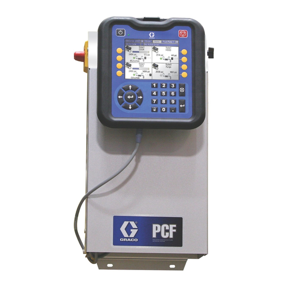
PCF
Precision Dispense System
Electronically-controlled fluid metering system that provides precise continuous flow of up
to four single-component sealants and adhesives through closed-loop technology.
Not for use in explosive atmospheres or hazardous locations.
For professional use only.
Important Safety Instructions
Read all warnings and instructions in this
manual. Save these instructions.
See page 4 for model information. See page 5 for
maximum working pressure and approvals.
IMPORTANT:
This manual does not apply to some PCF sys-
tems. See note on page 3 to verify this is the
correct manual for your PCF system.
3A2098A
EN
Advertisement
Table of Contents
Troubleshooting

Related Manuals for Graco PCF


Summary of Contents for Graco PCF
- Page 1 See page 4 for model information. See page 5 for maximum working pressure and approvals. IMPORTANT: This manual does not apply to some PCF sys- tems. See note on page 3 to verify this is the correct manual for your PCF system.
-
Page 2: Table Of Contents
Contents Related Manuals ......3 Shutdown ....... . 50 Models . -
Page 3: Related Manuals
Fluid Pressure Regulators Instruc- 308647 tions-Parts Graco Information ......124 Helical Gear Fluid Flow Meters Instruc- 309834... -
Page 4: Models
Check the identification (ID) plate for the 6-digit part number of the fluid metering system. Use the following matrix to define the construction of the system, based on the six digits. For example, Part PF1110 represents a PCF fluid ™... -
Page 5: Fluid Plate Kits
Models Fluid Plate Kits NOTE: The fluid plate kit numbers listed below include a CAN splitter. The fluid plate assembly included in each PFxxxx assembly does not include a CAN splitter. Includes: Fluid Used by Regula- Flow FCM Key Maximum Working Plate Kit Model Description... -
Page 6: Gateway Assemblies
Warnings Gateway Assemblies Each user interface comes with a gateway assembly. If you need to order a replacement gateway, see the fol- lowing table. User Interface Gateway Part Number To PCF Model Description Order PFxx0x Discrete 24B681 PFxx1x ™ 15V759... - Page 7 Warnings WARNING FIRE AND EXPLOSION HAZARD Flammable fumes, such as solvent and paint fumes, in work area can ignite or explode. To help prevent fire and explosion: • Use equipment only in well ventilated area. • Eliminate all ignition sources; such as pilot lights, cigarettes, portable electric lamps, and plastic drop cloths (potential static arc).
-
Page 8: System Configurations
System Configurations System Configurations Typical Ambient System Installation Power In Air Supply Drop Site . 1: Typical Ambient System Installation Key: *Control Center (User Interface) *CAN Cable *Fluid Plate Assembly G Fluid Supply System Applicator/Dispense Valve Fluid Supply Hose Sealer Automation Automation Controller Automation Interface Cable *Air Filter Assembly... -
Page 9: Typical Heated System Installation
System Configurations Typical Heated System Installation Power In Air Supply Drop Site . 2: Typical Heated System Installation Key: AA *Control Center (User Interface) AG Heated Fluid Supply System AB *Fluid Plate Assembly AH Fluid Supply Hose AC Applicator/Dispense Valve AJ Heat Control AD Sealer Automation AK Automation Controller... -
Page 10: Typical Multiple Fluid Plate System Installation
System Configurations Typical Multiple Fluid Plate System Installation Power In Air Supply Drop Site . 3: Typical Multiple Fluid Plate System Installation Key: *Control Center (User Interface) *CAN Cable *Fluid Plate Assembly G Fluid Supply System Applicator/Dispense Valve Fluid Supply Hose Sealer Automation Automation Controller Automation Interface Cable... -
Page 11: Overview
Bead dispensing • Gasketing The fluid plate assembly contains components that con- • Seam sealing trol and monitor fluid dispensing. A PCF fluid metering • Hem flange system can have up to four fluid plates. Each fluid plate • Sound deadening can control up to four dispense valves. -
Page 12: Fluid Plate Assembly Overview
Overview Fluid Plate Assembly Overview The PCF fluid regulator is electrically controlled by the PCF fluid control module. Consistent material flow is assured by a closed-loop pressure or closed-loop flow Fluid Plate Components control design. The module responds to automa-... - Page 13 Overview Fluid Regulator Fluid Control Module (FCM) There are three fluid regulator options: • cartridge • ambient mastic • heated mastic All of the fluid regulator options use air pressure to con- trol fluid pressure, provide fast response to electronic commands, and ensure a precisely controlled, continu- Status ous flow of material.
-
Page 14: Control Center Assembly Overview
Overview Control Center Assembly Overview Front View Side View Open View Gateway Module (100-240 Vac Assembly) (24 Vdc Assembly) . 7: Control Center Components The control center includes the following components: • Advanced Display Module (ADM) with USB; see • Gateway Module, which can be one of the following page 15 for details. - Page 15 Overview Advanced Display Module (ADM) TI12362a r_24E451_3B9900_1a . 8: Advanced Display Module Component Identification KEY: Callout Function Navigation Buttons Callout Function Navigate within a screen or to a new screen. Power On/Off Button Flat Panel Mount Enables/disables system. Mounts to control center bracket (optional). System Status Indicator LED Model Number Tag Displays system status.
- Page 16 Overview Gateway Module The Discrete Gateway Module (DGM) rotary switch must be in position 0 in order the for the DGM to operate.The Communications Gateway Module (DGM) rotary switch can be in any position. Front Back Front (Access Cover Removed) See Gateway Module Connector Table Rotary...
-
Page 17: Key Tokens
FCM Key Token, 16 styles, Flow Meter 16M103 FCM Key Token, 16 styles, No Flow Meter 16M104 FCM Key Token, 256 styles, Flow Meter 16M105 FCM Key Token, 256 styles, No Flow Meter 16M217 ADM Key Token, Standard PCF 3A2098A... -
Page 18: Installation
Installation Before Installation Overview • Have all system and component documentation The basic steps to install a PCF system are shown available during installation. below. See the separate component manuals for detailed information. • See component manuals for specific data on compo- nent requirements. -
Page 19: Install Control Center
See the mounting dimensions in Table 2 and Mount . 11. Ensure the following criteria are met before mounting Table 2: Control Center Assembly Measurement the PCF control center: 10.50 in. (267 mm) • Select a location for the control center that allows 5.75 in. (146 mm) adequate space for installation, service, and use of 17.00 in. - Page 20 Use a protective grommet where the 1. Order the 255468 Light Tower Accessory as a diag- power wiring enters the enclosure to prevent wear. nostic indicator for the PCF system. • Refer to your local code for the requirements for a “true earth ground”...
-
Page 21: Install Fluid Plate Assemblies
Mount Before Mounting Assembly • See component manuals for specific information on component requirements. Information presented here pertains to the PCF fluid plate assembly only. • Have all system and subassembly documentation available during installation. • Be sure all accessories are adequately sized and pressure-rated to meet the system's requirements. - Page 22 Mount Four-Valve Breakout Kit 24B693 5. Connect the dispense valve cable(s) to the connec- tions on the splitter assembly. PCF is capable of controlling up to four separate dis- pense valves from port 1 on the FCM. A four-valve Connects to Splitter...
-
Page 23: Install Bulkhead Fitting (Included In The Kit) Into The Empty Hole On The Fluid Plate
Pink No connection Blue Command signal ground No connection NOTE: Command cable inputs are not isolated from PCF 24 Vdc power. To turn on the dispense trigger, connect pin 3 (dis- pense trigger) to pin 5 (dispense trigger ground). 3A2098A... -
Page 24: Dispense Valve
• The PCF fluid plate assembly should be installed on • All wires used for grounding must be 18 AWG min- the automation unit or in another appropriate place, imum. -
Page 25: Install Cable Assemblies
Installation Install Cable Assemblies 1. Connect the CAN cable from the control center to 3. Use the automation interface cable to connect the one fluid plate assembly. Gateway module to the automation controller. 2. For multiple fluid plate systems, use a CAN cable to connect each fluid plate to one other fluid plate. -
Page 26: Install Gateway Module Interface
The Communications Gateway Module (CGM) provides used. Ensure the installer understands the automa- a control link between the PCF system and a selected tion controller communication architecture and the fieldbus. This provides the means for remote monitoring fieldbus being used. - Page 27 This provides the means for remote monitoring and con- trol by external automation systems. See Automation Control (Normal Operation), page 41, for details on controlling the PCF system through the Gateway module. Connect D-Sub Cable The DGM provides all I/O through the D-Sub cable.
-
Page 28: System Setup
However, if there is a hardware Configure System (page 29) change on the supply system or the dispense material is changed, the PCF system must be set up again. Configure Control Settings (page 30) After material is loaded into the supply system, set up the PCF system using the Setup screens. -
Page 29: Configure System
System Setup Configure System Define the number of installed fluid plates. If a fluid plate is listed as “Uninstalled” the screens for that fluid plate will not appear in the run or setup screens. 1. With the system in setup mode, navigate to the Sys- tem screen. -
Page 30: Configure Control Settings
System Setup Configure Control Settings 7. Press to move to the Job End Delay field. Enter Set the controls for the dispense source, how dispense the desired delay time (in seconds). Press commands are sent, and job settings. enter the value. 1. -
Page 31: Configure Mode Settings
System Setup Configure Mode Settings NOTE: The ability to dispense from multiple valves simultaneously is only allowed in either of the fol- lowing scenarios. Set valve commands, including the dispense mode (pressure, bead, shot, or full open) and flow rate or pres- •... -
Page 32: Configure Delay Settings
. 23 Configure Flow Meter Settings The accuracy of the PCF volume reporting depends on precise adjustment of the K-factor(s). The fluid plate uses the K-factor(s) to calculate the volume dispensed. If the set value is not correct, the system still delivers repeatable flow rates;... -
Page 33: Configure Pressure Loop Settings
See Verify Flow Meter Calibration, page 39, for instructions. Configure Pressure Loop Settings The PCF system uses variables (Kp and Ki) in the soft- . 24 ware calculations to accurately and precisely control the fluid pressure. NOTE: For the following steps, press NOTE: It is recommended that these values not be changed from the factory defaults of 32.00 for Kp... -
Page 34: Configure Errors
System Setup Configure Errors Setup Maintenance Schedule/Parameters Set the error type (alarm, deviation, or none) that will be issued if the pressure, flow rate, volume, or computed Set the volume (or hours) limit that will trigger a mainte- target goes outside the tolerance settings of the active nance advisory for the fluid supply, Voltage to Pressure style. -
Page 35: Configure Gateway Settings
Setup Screens, page 92, for guidelines on configuring each type of Gateway interface. Setup Styles The PCF system can store up to 256 styles. See Styles, page 42, for more information about styles and instruc- tions on setting up styles. Style 0 is always the purge style. -
Page 36: On/Off Delays
On/Off Delays . 27 and Table 6: Delay On/Off Timing show delay ON and OFF timing. The PCF fluid regulator can physically respond faster Table 6: Delay On/Off Timing than the dispense device and its solenoid. As a result, A Regulator ON... -
Page 37: Operation
3. Turn on air and electrical power to the system. 4. Turn on the main power to supply power to the PCF. 7. Press and hold . Dispense fluid until clean, air-free fluid flows from the valve. -
Page 38: Maintenance Mode Operation
Use maintenance mode to manually check the operation ation, dispense at each pressure or flow rate that of the PCF system components before switching over to will be used during normal operation. This verifica- automation control (normal operation). See Dispense... - Page 39 Operation Verify Flow Meter Calibration 3. Manually dispense material into the beaker. Hold the beaker so that the stream of material is sub- Most sealant and adhesive materials are compressible. merged in the captured material to minimize air Since the flow meter measures the material under high entrapment in the container.
- Page 40 Operation Dispense From Maintenance Screen 4. Press to move to the target fields. Enter the tar- 1. Navigate to Fluid Plate x, screen 1 for the desired get pressure, flow rate, or volume (dependent on fluid plate. control mode) and press to save.
-
Page 41: Automation Control (Normal Operation)
A job is initiated when the automation sends a Style ume for pressure mode. Strobe signal to the PCF. Once the job is initiated, the PCF will start tracking the amount of volume requested Continuously Running Applications by the automation and the amount of material that is actually dispensed. -
Page 42: Styles
Styles 3. Enter the style number in the Style field. 4. Enter Style Name: The PCF system has the ability to handle up to 256 styles, depending on the selected option. a. Press while in the Style Name field to dis- NOTE: The number of available styles depends on play the Keyboard screen. -
Page 43: Typical Job Cycle
3. The automation controller sets the Style Strobe to 1. The following limitations apply when starting a job with 4. PCF reads the Style bits to select the new style. The this configuration: system then starts a new job and sets Dispense In Process to 1. - Page 44 Operation Typical Job Cycle Chart 3A2098A...
-
Page 45: Dispense Valve 3 J3
Operation Control Charts Purge Using Style 0 Automation Inputs (PCF Outputs) Dispense Ready Dispenser (Fluid Plate) No Alarm Dispenser (Fluid Plate) No Error Dispense In Process Purge In Process Volume OK Automation Outputs (PCF Inputs) Style Bits Style Strobe Dispense Valve X On... - Page 46 Operation Control Charts (continued) Remote Start Automation Inputs (PCF Outputs) Dispenser (Fluid Plate) Ready Dispenser (Fluid Plate) No Alarm Dispenser (Fluid Plate) No Error Dispenser (Fluid Plate) Remote Start/Purge in Process Automation Outputs (PCF Inputs) Remote Start/Purge Error Reset Automation Inputs (PCF Outputs)
- Page 47 Fluid Plate x, screen 1(Control Settings). Trigger Using Gateway Automation Inputs (PCF Outputs) Dispense In Process Automation Outputs (PCF Gateway Inputs) Dispense Valve 1 On Dispense Valve 2 On Dispense Valve 3 On Dispense Valve 4 On...
- Page 48 Operation Control Charts (continued) Trigger Using Command Cable and Gateway Automation Inputs (PCF Outputs) Dispense In Process Automation Outputs (PCF Gateway Inputs) Dispense Valve X On Dispense Valve Y On Command Cable Dispense Trigger PCF State Regulator Active (Precharge = 0)
-
Page 49: Pressure Relief Procedure
Pressure Relief Procedure Pressure Relief Procedure b. Continue actuating the plunger until all pressure is purged from the system between the needle and the dispense valves attached to this fluid This equipment stays pressurized until pressure is plate before proceeding to the next step. manually relieved. -
Page 50: Shutdown
2. Shut off the material supply to the fluid plate/meter. 3. Follow the Pressure Relief Procedure on page 49. 4. Turn off the PCF system's compressed air supply. 5. Turn main power switch on control panel to the OFF position. -
Page 51: Usb Data
Average flow rate during job (measured in related information to memory in the form of log files. cc/min, systems with no flow meter will read 0) PCF maintains three types of log files: a job log, an • Maximum flow rate during job (measured in event log, and dispense data logs. -
Page 52: System Configuration Settings File
USB flash drive is inserted. Use this file to back up system settings for future recovery or to The PCF system is able to display the following Unicode easily replicate settings across multiple PCF systems. characters. For characters outside of this set, the sys-... -
Page 53: Download Procedure
8. Open DOWNLOAD folder. 8. Remove USB flash drive from computer. 9. Open LOG FILES folder labeled with the highest 9. Install USB flash drive into PCF system USB port. number. The highest number indicates the most recent data download. -
Page 54: Troubleshooting
Troubleshooting Troubleshooting NOTE: Check all possible solutions in the chart Troubleshooting for individual fluid regulators and flow below before you disassemble the system. meters is also discussed in their separate manuals; refer to Related Manuals on page 3. Also refer to Event and Error Codes and Troubleshooting, page 59, for detailed information on how error codes are communi- cated. -
Page 55: Flow Meter
Troubleshooting Flow Meter Problem Cause Solution No flow measurement Flow meter pick-up sensor loose Tighten flow meter pick-up sensor Flow too low Verify flow rate is above minimum for the installed flow meter Loose wiring Verify connection from flow meter to Damaged flow meter pick-up sensor Replace pick-up sensor False measurement... -
Page 56: Dispense Valves
Troubleshooting Dispense Valves Problem Cause Solution Valve not opening Air not getting to the open port Verify air pressure to solenoid No “Valve On” signal from automa- Check input from automation unit tion unit Valve not shutting off Air not getting to the close port Verify air pressure to solenoid (except AutoPlus valve) Verify solenoid operation... -
Page 57: Gateway Module
Problem Cause Solution No communication Incorrect wiring Check wiring per fieldbus standard. Refer to PCF Gateway LED status indicators and Appendix C - Com- munications Gateway Module (CGM) Connection Details, page 111. Incorrect fieldbus settings Confirm fieldbus settings at automa- tion controller (fieldbus master) and PCF Gateway (fieldbus slave). -
Page 58: Errors
Errors Errors View Errors When an error occurs, an error pop-up is displayed that takes up the entire screen until the error is acknowl- edged by pressing . Errors can also be acknowl- edged over the gateway. Active errors are displayed in the menu bar. -
Page 59: Event And Error Codes And Troubleshooting
Errors Event and Error Codes and Troubleshooting NOTE: Error codes are stored in the events log and are displayed on the error report screens. Gateway error numbers are reported over the Gateway interface. NOTE: Error codes shown as XYZ_ represent error codes XYZ1, XYZ2, XYZ3, XYZ4, where the last digit rep- resents the number of the fluid plate to which the error applies. - Page 60 Verify the key token is Error token required to run the installed system Verify the key token part number is correct for the PCF ADM WNG0 Gateway Map Missing or invalid map Advisory Missing or invalid Install PCF map in Error...
- Page 61 Errors Event Gateway Event Code Error No. Event Name Description Event Type Cause Solution Fluid Plate Events and Errors B1C_ Low Computed Requested volume/ Alarm or Entered process target Enter correct process B2C_ Target mass differs from Deviation incorrectly target entered process target (user select- Entered tolerance...
- Page 62 Errors Event Gateway Event Code Error No. Event Name Description Event Type Cause Solution Fluid Plate Events and Errors WED_ V/P Error Voltage to Pressure Alarm Problem detected with Verify outlet pressure Transducer error transducer is installed and/or connected cor- rectly Replace if necessary WJ1_...
- Page 63 Errors Event Gateway Event Code Error No. Event Name Description Event Type Cause Solution Fluid Plate Events and Errors V2D_ Low Analog Analog command Deviation Bad or loose com- Check command cable dropped below mini- mand cable connec- and connection mum value (user tion defined) while dispens-...
- Page 64 No action required if by Job Timer terminated by job timer used to stop shot dis- timed shot is desired pense EHD_ Purge Timer Purge timer expired Advisory PCF purge timer (style Automation control Expired 0) has expired requests purge 3A2098A...
- Page 65 Errors Event Gateway Event Code Error No. Event Name Description Event Type Cause Solution Fluid Plate Events and Errors EAC_ Maintenance Maintenance mode Advisory Entered maintenance No action required Mode Entered entered (self-clearing) dispense mode EBC_ Maintenance Maintenance mode Advisory Exited maintenance No action required Mode Exited...
-
Page 66: Maintenance
Maintenance Maintenance Prior to performing any maintenance procedures, follow the Pressure Relief Procedure on page 49. Maintenance Schedule The following tables list the recommended maintenance procedures and frequencies to operate the equipment safely. The maintenance is divided between mechanical and electrical tasks. Maintenance must be performed by trained personnel per this schedule to assure safety and reliability of the equipment. -
Page 67: Advanced Display Module (Adm)
Maintenance Advanced Display Module (ADM) Upgrade Gateway Module Software Upgrade Software NOTE: The Gateway module connection to the sys- NOTE: Back up the custom language file (if tem is temporarily disabled during the use of installed) before upgrading software. See USB Data, upgrade tokens. -
Page 68: Upgrade Gateway Module Fieldbus Map
Maintenance Upgrade Gateway Module 3. Press and hold the push button for three seconds and then release. The red indicator light (CK) will Fieldbus Map flash twice, pause, and then once after the data map is uploaded. NOTE: The fieldbus connection is temporarily dis- abled during the use of a map token. -
Page 69: Upgrade Fluid Control Module (Fcm) Software
Maintenance Upgrade Fluid Control Module 7. Reinstall key token, and replace access cover. (FCM) Software Air Filter Maintenance NOTE: The FCM connection is temporarily disabled during the use of the upgrade token. To prevent filter element damage, replace air filter every two years or when pressure drop becomes 100 kPa 1. -
Page 70: Repair
Repair Repair Fluid Plate Assembly Repair Flow Meter For complete flow meter (129) repair instructions refer to the maintenance and repair section of manual 309834. Remove Flow Meter from Mounting Plate This section describes how to remove and replace com- 1. - Page 71 Repair Install Flow Meter on Mounting Plate 4. Remove the dispense valve solenoid (132) and replace it with a new solenoid. 1. Rest the flow meter (129) and bracket (124) on the fluid plate while threading the swivel fitting (109) onto the regulator material inlet.
- Page 72 Repair 5. Secure the new V/P transducer to the bracket with Replace Fluid Control Module Base screws. 1. Prepare Fluid Plate Assembly for Repair, page 6. Reconnect the FCM cable and both air tubes. 2. Remove the FCM (103); follow Replace Fluid Con- Replace Fluid Control Module trol Module.
- Page 73 Repair Replace Transducer O-Rings 1. Prepare Fluid Plate Assembly for Repair, page 2. Remove the fluid outlet pressure sensor (117) from the regulator (108). r_pf0000_313377_16a . 51 3. Press the transducer (CG) out of the retainer nut (CH). 4. Remove the faulty o-ring (120) and replace with new.
- Page 74 Repair Repair Fluid Regulator NOTE: The retaining nut (CC) often loosens when removing the cartridge assembly from the base For complete cartridge fluid regulator repair refer to housing. Be sure to re-torque as described in step 4. instruction manual 308647. For complete mastic fluid regulator repair refer to instruction manual 307517.
- Page 75 Repair Replace Amplifier 3. Loosen four screws on amplifier (116) cover, and then remove cover. (Heated fluid plates only) 4. Remove four screws (105) securing amplifier to 1. Prepare Fluid Plate Assembly for Repair, page bracket. 5. Remove amplifier and replace with a new amplifier. 2.
- Page 76 Repair Calibrate Amplifier 8. With the system still in setup mode, navigate to Fluid Plate x, screen 5 (Pressure Sensors). (Heated fluid plates only) 1. Prepare Fluid Plate Assembly for Repair, page 2. Remove outlet pressure sensor from outlet fitting to ensure there is no pressure applied to the sensor.
- Page 77 Shunt Calibration 17. Use the data from the certificate of calibration for Pressure. the pressure sensor (included with PCF documenta- tion or the replacement pressure sensor) to calcu- 19. Remove the jumper wire or paper clip from the late the Shunt Calibration Pressure using the SHUNT CAL and ENABLE terminals.
-
Page 78: Control Center Assembly
Repair Control Center Assembly Replace Gateway Module Base 1. Prepare Control Center for Repair, page 78. 2. Remove the Gateway module (5); follow Replace Gateway Module. (Leave automation communica- tions cable (AE) attached to Gateway module.) Prepare Control Center for Repair 3. - Page 79 Repair Replace Advanced Display Module Replace Advanced Display Module Bracket 1. Prepare Control Center for Repair, page 78. 1. Prepare Control Center for Repair, page 78. 2. Remove the ADM (2); follow Replace Advanced 2. Disconnect the CAN cable (18) from the ADM (2). Display Module.
- Page 80 Repair Replace DIN Rail Assembly 7. Reconnect all wiring to the din rail module, filter, and rocker/rotary switch. 1. Prepare Control Center for Repair, page 78. 8. Reassemble the line voltage assembly cover using 2. Remove both screws (22) and washers (28) from the screws and washers.
- Page 81 Repair 3A2098A...
-
Page 82: Parts
Parts Parts This section applies only to series A models. To determine the series of your system, see the identification label on the system. For Parts, see page 82. Control Center Assembly Parts r_pf0000_313377_11a 24 Vdc Din Rail Assembly Shown Components of 24 Vdc Module Kit (24B929) and 100-240 Vac Line Voltage Module Kit... - Page 83 ★ 16K742 Historical PCF Gateway map token: Only for ★15V760 PFxx2x Ether- users that used the original PCF with a Gate- ™ Net/IP way, have purchased a new PCF, and do not ★15V761 wish to change their Gateway setup from the PFxx3x ™...
-
Page 84: Fluid Plate Assembly Parts
Parts Fluid Plate Assembly Parts See page 86 See page 85 135, 136 See page 85 3A2098A... - Page 85 Parts Fluid Plate Assembly Parts (continued) 3A2098A...
- Page 86 Parts Fluid Plate Assembly Parts (continued) 117, 120 Fluid Plate 24B962 Shown 105, 116 140, 141, 150 3A2098A...
- Page 87 198269 BRACKET, flow meter, lower mastic regulator. 110580 SCREW, cap, socket hd 113✓ SPACER ✠ Base electronic components do not have PCF-spe- 198268 BRACKET, flow meter cific software installed. Therefore, use software 115✖ 624545 FITTING, tee; 3/4(m) x 1/4(f) upgrade token (16K743) to install software before 116✖...
- Page 88 Parts Parts Varying by Assembly The following table lists the varying part numbers by fluid plate assembly, and the quantity for each assembly. Fluid Plate Assemblies Heated Mastic Cartridge Mastic Regulator Heated Regulator Cartridge Regulator Mastic with Heated Mastic with High Regulator with High Regulator...
-
Page 89: Appendix A - Advanced Display Module (Adm)
Appendix A - Advanced Display Module (ADM) Appendix A - Advanced Display Module (ADM) Display Overview Display Details The ADM display is divided into two main functions: Power Up Screen Setup Mode and Run Mode. The following screen appears when the ADM is powered Setup Mode Functions up. - Page 90 Appendix A - Advanced Display Module (ADM) System Mode Navigation within Screens There are four modes: Active, Job in Cycle, Display Press to open drop-down menus on Setup Control, and System Off. The current system mode is screens. Also, press to enter changes or make a displayed at the left of the menu bar.
-
Page 91: Setup Mode
Appendix A - Advanced Display Module (ADM) Setup Mode Advanced Setup Screen 2 This screen enables users to set the units of measure Setup mode screens are divided into four sections: Sys- for maintenance volume, maintenance mass, pressure, tem setup, Advanced setup, Gateway setup, and Fluid and flow rate. - Page 92 This screen enables users to set the IP address, subnet information regarding the Gateway module used on the mask, Gateway, DNS 1, DNS 2, and if a DHCP is used. PCF system. These screens also enable users to view information regarding the particular Gateway module used.
- Page 93 Gateway Setup Screen 3 - PROFINET See Gateway Setup Screen 2 - EtherNet/IP, page 92, for details. This screen enables users to view the following informa- tion regarding the Gateway module used on the PCF system: Gateway Setup Screen 1 - PROFINET •...
- Page 94 Type signal (Analog or Digital) the automation system Input 1 Input 2 Command Selection will provide to PCF. If Analog control is selected, the Fluid Plate 1, user must provide an analog voltage to the proper input Setting #1 on the DGM. See Appendix B - Discrete Gateway...
- Page 95 Appendix A - Advanced Display Module (ADM) Fluid Plate Setup Screens There are eight fluid plate setup screens, which enable Fluid Plate x, Screen 2 (Mode Settings) users to: This screen enables users to set valve commands. Use this screen to select a mode (pressure, bead, shot, or •...
- Page 96 Appendix A - Advanced Display Module (ADM) Fluid Plate x, Screen 3 (Delay Settings) Fluid Plate x, Screen 5 (Pressure Sensors) This screen enables users to set on and off delays (in NOTE: Inlet sensor settings will be grayed out on this screen for systems with heated fluid plates.
- Page 97 Appendix A - Advanced Display Module (ADM) Fluid Plate x, Screen 6 (Error Type) Fluid Plate x, Screen 7 (Maintenance Advisory Limits) This screen enables users to set the error type (none, alarm, or deviation) that will be issued if the pressure, This screen enables users to set volume (or hours) limit flow rate, volume, or computed target goes outside the that will trigger a maintenance advisory for the air sup-...
- Page 98 Appendix A - Advanced Display Module (ADM) Fluid Plate x, Screen 8 (Style) Keyboard Screen This screen enables users to set up to 256 styles, Use all four arrow buttons to select each letter; press depending on system configuration. Press to enter the letter.
-
Page 99: Run Mode
Appendix A - Advanced Display Module (ADM) Run Mode Run mode screens are divided into five sections: home, fluid plates, events, errors, and jobs. While in Setup mode press to enter Run mode. Press to navigate through the Run mode screens. Home Screen The Home screen shows an overview for each of the individual fluid plates. - Page 100 Appendix A - Advanced Display Module (ADM) Fluid Plate x, Screen 1 The PCF system has two operating modes: This screen displays the current dispense control mode • Dispense mode – enables the module to begin dis- used, the current pressure, and the current style being pensing when it receives a command from the auto- dispensed.
- Page 101 • Pressure Control – the regulator outlet pressure is controlled to the requested value. • Full Open Control – the PCF system does not con- trol fluid pressure or flow. Instead the regulator opens to allow for recirculation applications. 3A2098A...
- Page 102 Appendix A - Advanced Display Module (ADM) Fluid Plate x, Screen 2 (Control Center) Fluid Plate x, Screen 3 (Maintenance Totalizers) This screen enables users to view the maintenance NOTE: Users must be out of maintenance mode in totalizers for each system component and the limits set Fluid Plate x, screen 1 in order to scroll to this that will trigger a maintenance advisory.
- Page 103 Appendix A - Advanced Display Module (ADM) Job Report Screens Error Report Screens The job report screens store and display a chronological The error report screens display a chronological list of list of 180 jobs performed by the system. Each job system errors.
-
Page 104: Appendix B - Discrete Gateway Module (Dgm) Connection Details
Appendix B - Discrete Gateway Module (DGM) Connection Details Appendix B - Discrete Gateway Module (DGM) Connection Details D-Sub Cable 123793 The D-sub cable 123793 is only compatible with single fluid plate systems. Systems with 2 fluid plates must use cable 123792 and breakout board 123783. -
Page 105: D-Sub Cable 123792 And Breakout Board 123783
Appendix B - Discrete Gateway Module (DGM) Connection Details D-Sub Cable 123792 and Breakout Board 123783 The cable length of the interface cable assembly 123792 is 50 ft (15.2 m). The following table identifies the pin assignments for the 78-pin breakout board. NOTE: See Appendix D - I/O Signal Descriptions, page 120, for I/O signal descriptions. - Page 106 Appendix B - Discrete Gateway Module (DGM) Connection Details D-Sub Pin No. Description Pin Type Voltage (Vdc) Isolated Logic Power Supply Isolated Logic Supply V+ 10-30 Style Bit 1 Digital In 0-30 Style Bit 2 Digital In 0-30 Style Bit 3 Digital In 0-30 Style Bit 4...
- Page 107 Appendix B - Discrete Gateway Module (DGM) Connection Details Pin References NOTE: To avoid ground loops and noise immunity issues, do not ground the shield of the D-subminia- ture connector cable; it is already grounded through the mounting screw on the base of the DGM. .
-
Page 108: Dgm Digital Input
Appendix B - Discrete Gateway Module (DGM) Connection Details DGM Digital Input The digital inputs function only when power is supplied to pin 51 and there is a ground connection to pin 70. See Pin References, page 107, for details. The digital input is rated at 0-30 Vdc, and requires an NEC Class 2 power supply connected to pin 51. -
Page 109: Dgm Digital Outputs
Appendix B - Discrete Gateway Module (DGM) Connection Details DGM Digital Outputs The digital outputs function only when power is supplied to pins 27, 68, and 69 and there is a ground connection to pin 70. See Pin References, page 107, for details. The digital output is rated at 0-30 Vdc, and requires an NEC Class 2 power supply connected to pin 27 for supply bank 1, pin 69 for supply bank 2, and pin 68 for supply bank 3. -
Page 110: Dgm Analog Inputs
Appendix B - Discrete Gateway Module (DGM) Connection Details DGM Analog Inputs The analog inputs function only when the DGM is connected to a power supply through the CAN connection. Each analog input has a corresponding reference (ground) pin. See Pin References, page 107, for details. •... -
Page 111: Appendix C - Communications Gateway Module (Cgm) Connection Details
Appendix C - Communications Gateway Module (CGM) Connection Details Appendix C - Communications Gateway Module (CGM) Connection Details Install Fieldbus Connections Module Status (MS) Connect cables to fieldbus per fieldbus standards. State Description Comments Not initial- No power or module in PROFINET ized “SETUP”... - Page 112 Appendix C - Communications Gateway Module (CGM) Connection Details Module Status (MS) Module Status (MS) State Description State Description No power No power or not initialized Green Controlled by a Scanner in Run state Green Initialized Flashing Not configured, or Scanner in Idle state Flashing Missing or incomplete configuration, device Green...
- Page 113 Appendix C - Communications Gateway Module (CGM) Connection Details Operation Mode (OP) PROFIBUS Connector (DC) State Description Signal Description Not online / No power Green On-line, data exchange B Line Positive RxD/TxD, RS485 level Flashing On-line, clear Request to send Green GND Bus Ground (isolated)
-
Page 114: Cgm I/O Data Map
Appendix C - Communications Gateway Module (CGM) Connection Details CGM I/O Data Map Automation Inputs (signals from PCF) Input Input Byte Description Zone Byte Description Zone Dispenser (Fluid Plate) Ready Dispenser (Fluid Plate) Ready Dispenser (Fluid Plate) No Alarm Dispenser (Fluid Plate) No Alarm... - Page 115 Appendix C - Communications Gateway Module (CGM) Connection Details Input Input Byte Description Zone Byte Description Zone Dispenser (Fluid Plate) Ready Dispenser (Fluid Plate) Ready Dispenser (Fluid Plate) No Alarm Dispenser (Fluid Plate) No Alarm Dispense No Error Dispense No Error Dispense in Process Dispense in Process Dispense Volume OK...
- Page 116 Appendix C - Communications Gateway Module (CGM) Connection Details Input Input Byte Description Zone Byte Description Zone I128 I168 - I175 I129 I176 - I130 I183 I131 I184 - I132 I191 I133 I192 - I134 I199 I135 I136 I137 I138 I139 I140 I141...
- Page 117 Appendix C - Communications Gateway Module (CGM) Connection Details Automation Outputs (signals to PCF) Output Output Byte Description Zone Byte Description Zone Style Strobe Style Strobe Dispense Complete Dispense Complete Dispense Valve 1 On Dispense Valve 1 On Dispense Valve 2 On...
- Page 118 Appendix C - Communications Gateway Module (CGM) Connection Details Output Output Byte Description Zone Byte Description Zone O128 Style Strobe O192 Style Strobe O129 Dispense Complete O193 Dispense Complete O130 Dispense Valve 1 On O194 Dispense Valve 1 On O131 Dispense Valve 2 On O195 Dispense Valve 2 On...
- Page 119 Appendix C - Communications Gateway Module (CGM) Connection Details Output Byte Description Zone O256 - O263 O264 - O271 O272 - O279 O280 - O287 O288 - O295 O296 - O303 O304 - O311 O312 - O319 O320 - O327 3A2098A...
-
Page 120: Appendix D - I/O Signal Descriptions
Appendix D - I/O Signal Descriptions Appendix D - I/O Signal Descriptions Automation Inputs Dispenser (Fluid Plate) Remote Start / Purge in Process This signal is 0 on power up. This signal will be 1 under Dispenser (Fluid Plate) Ready the following conditions: This signal is 0 on power up. -
Page 121: Automation Outputs
Appendix D - I/O Signal Descriptions Automation Outputs Style The desired style of the next job. These 8 bits are read at the start of a job to determine the selected style. Style Strobe This bit is used to start a new job. A new job is started when the style strobe changes from 0 to 1. -
Page 122: Technical Data
* Flow rates and viscosities are general estimates. Flow rates drop as viscosity increases. Fluids are expected to shear under pressure. New applications or fluids should always be tested to determine proper line sizes and equip- ment selections. See your Graco authorized distributor for other capabilities. 3A2098A... -
Page 123: Fluid Plate Assembly Technical Data
Technical Data Fluid Plate Assembly Technical Data Mounting dimensions and parts breakdowns for the fluid plate assemblies are in the installation section of this man- ual. Cartridge Regulator Mastic Regulator Regulator Manual 308647 307517 Weight - No Flow Meter 25.5 lbs (11.6 kg) 33 lb (15 kg) Weight - Helical 40 lbs (18 kg) -
Page 124: Graco Standard Warranty
With the exception of any special, extended, or limited warranty published by Graco, Graco will, for a period of twelve months from the date of sale, repair or replace any part of the equipment determined by Graco to be defective.
Need help?
Do you have a question about the PCF and is the answer not in the manual?
Questions and answers