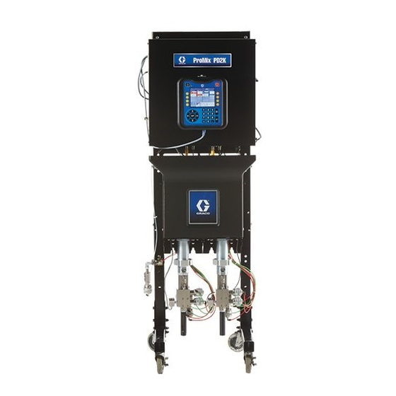
Graco ProMix PD2K Electronic Operation
Proportioner
Hide thumbs
Also See for ProMix PD2K Electronic:
- Operation (180 pages) ,
- Repair parts (82 pages) ,
- Installation manual (62 pages)
Table of Contents
Advertisement
Quick Links
Operation
ProMix® PD2K Electronic
Proportioner
Positive displacement proportioning of 2-component materials helps reduce waste. Manual system with
Advanced Display Module. For professional use only.
Important Safety Instructions
Read all warnings and instructions in this manual and in your PD2K
Installation and Repair/Parts manuals.
Save these instructions.
See page 3 for model part numbers and
approvals information.
PROVEN QUALITY. LEADING TECHNOLOGY.
332562B
EN
Advertisement
Table of Contents

Related Manuals for Graco ProMix PD2K Electronic


Summary of Contents for Graco ProMix PD2K Electronic
- Page 1 Operation ProMix® PD2K Electronic 332562B Proportioner Positive displacement proportioning of 2-component materials helps reduce waste. Manual system with Advanced Display Module. For professional use only. Important Safety Instructions Read all warnings and instructions in this manual and in your PD2K Installation and Repair/Parts manuals.
-
Page 2: Table Of Contents
Preventive Maintenance Schedule ....74 Spray Screen..........34 Flushing ............74 Fill Screen ........... 35 Cleaning the ADM ........74 Usage Screen..........36 Technical Data ........... 75 Jobs Screen ..........37 Errors Screen ..........37 Graco Standard Warranty........76 332562B... -
Page 3: Models
Models Models See Figs. 1–7 for component identification labels, including approval information and certification. Part No. Series Maximum Air Working Maximum Fluid Working Location of PD2K and Pressure Pressure Electrical Control Box (ECB) Labels With low- pressure pumps: 300 psi (2.068 MPa, 20.68 bar) MC0500 100 psi (0.7 MPa, 7.0 bar) - Page 4 Models Figure 3 Model MC2000 (High Pressure) Identification Label Figure 4 Model MC0500 Identification Label Figure 5 Non-Intrinsically Safe Color Change Control (Accessory) Identification Label 332562B...
- Page 5 Models Figure 6 Intrinsically Safe Color Change Control (Accessory) Identification Label Figure 7 Booth Control Identification Label Figure 8 Pump Expansion Kit (Accessory) Identification Label 332562B...
-
Page 6: Related Manuals
Related Manuals Related Manuals Manual No. Description Manual No. Description 3A2800 PD2K Proportioner Repair-Parts 332455 Color Change Kits Instructions- Manual, Manual Systems Parts Manual 332457 PD2K Proportioner Installation 332456 3rd and 4th Pump Kits Manual, Manual Systems Instructions-Parts Manual 3A2801 Mix Manifold Instructions-Parts 334512 PD1K Pump Expansion Kits... -
Page 7: Warnings
Warnings Warnings The following warnings are for the setup, use, grounding, maintenance and repair of this equipment. The exclamation point symbol alerts you to a general warning and the hazard symbol refers to procedure-specific risks. When these symbols appear in the body of this manual or on warning labels, refer back to these Warnings. - Page 8 Warnings WARNING INTRINSIC SAFETY Intrinsically safe equipment that is installed improperly or connected to non-intrinsically safe equipment will create a hazardous condition and can cause fire, explosion, or electric shock. Follow local regulations and the following safety requirements. • Be sure your installation complies with national, state, and local codes for the installation of electrical apparatus in a Class I, Group D, Division 1 (North America) or Class I, Zones 1 and 2 (Europe) Hazardous Location, including all of the local safety fire codes (for example, NFPA 33, NEC 500 and 516, OSHA 1910.107, etc.).
- Page 9 Warnings WARNING TOXIC FLUID OR FUMES Toxic fluids or fumes can cause serious injury or death if splashed in the eyes or on skin, inhaled, or swallowed. • Read MSDSs to know the specific hazards of the fluids you are using. •...
-
Page 10: Important Isocyanate (Iso) Information
Important Isocyanate (ISO) Information Important Isocyanate (ISO) Information Keep Components A and B Separate Isocyanates (ISO) are catalysts used in two component materials. Isocyanate Conditions Cross-contamination can result in cured material in fluid lines which could cause serious injury or damage equipment. To prevent cross-contamination: Spraying or dispensing materials containing isocyanates creates potentially harmful mists,... - Page 11 Important Isocyanate (ISO) Information Changing Materials NOTICE Changing the material types used in your equipment requires special attention to avoid equipment damage and downtime. • When changing materials, flush the equipment multiple times to ensure it is thoroughly clean. • Always clean the fluid inlet strainers after flushing.
-
Page 12: Glossary Of Terms
Glossary of Terms Glossary of Terms Advanced Display Module (ADM) - the Potlife Time - the amount of time before a material user interface for the system. See becomes unsprayable. Advanced Display Module, page Potlife Volume - the amount of material that is required to move through the mix manifold, hose, and Enhanced Fluid Control Module (EFCM) - the fluid applicator before the potlife timer is reset. -
Page 13: Overview
Overview Overview Usage This electronic two-component paint proportioner • Can proportion at ratios from 0.1:1 to 50.0:1 can blend most two-component paints, including (depending on material, flow rate, pump size quick-setting paints (those with a pot life of 5 minutes selection, and mix point). - Page 14 Overview Typical Installation (MC1000, MC2000) HAZARDOUS (CLASSIFIED) LOCATION NON-HAZARDOUS LOCATION ONLY Figure 9 Description Component Components G through K are included in optional color change kits. Color Change Valves (accessory) Component Description Color Change Module (accessory) ★ Components A through F are included with the Catalyst Change Valves base unit.
- Page 15 Overview Typical Installation (MC0500) HAZARDOUS (CLASSIFIED) LOCATION NON-HAZARDOUS LOCATION ONLY Figure 10 Description Component Components G through K are included in optional color change kits. Color Change Valves (accessory) Component Description Color Change Module (accessory) ★ Components D, E, and F are included with the Catalyst Change Valves base unit.
-
Page 16: Advanced Display Module
6. The USB flash drive window automatically opens. If it does not, open the USB flash drive from within Windows® Explorer. 7. Open Graco folder. 8. Open system folder. If downloading data from more than one system, there will be more than one folder. -
Page 17: Usb Upload Procedure
Language drop-down menu in the Advanced Setup folder within the Graco folder. Each folder is Screen 1. labeled with the corresponding serial number of the ADM. -
Page 18: Adm Keys And Indicators
Advanced Display Module ADM Keys and Indicators NOTICE To prevent damage to the softkey buttons, do not press the buttons with sharp objects such as pens, plastic cards, or fingernails. Table 1 : ADM Keys and Indicators Function Press to startup or shutdown the pump/motor. •... -
Page 19: Soft Key Icons
Advanced Display Module Soft Key Icons NOTICE The following icons appear in the ADM display, directly to the left or right of the soft key which To prevent damage to the softkey buttons, do not activates that operation. press the buttons with sharp objects such as pens, plastic cards, or fingernails. - Page 20 Advanced Display Module Function Standby Press to stop all pumps and put system in Standby. Stop Press to start a pump pressure check. Pressure Check Press to start a pump volume check. Volume Check Press to log the material usage and increment the job number.
-
Page 21: Navigating The Screens
Advanced Display Module Navigating the Screens Screen Icons There are two sets of screens: As you move through the screens, you will notice that icons are used frequently to simplify global • The Run screens control mixing operations and communication. The following descriptions explain display system status and data. -
Page 22: Booth Control
Booth Control Booth Control Booth Control Display The booth control is the main control device used by the operator for daily painting functions including: changing recipes, signaling job complete, reading/clearing alarms, and placing the system in Standby, Mix, or Purge mode. It is typically mounted inside the booth or near the painter. -
Page 23: Booth Control Keys And Indicators
Booth Control Booth Control Keys and Indicators Key/Indicator Definition and Function • Red LED is solid when an alarm condition is present. • Red LED blinks when an event requiring user acknowledgement occurs at Alarm Reset Key and any level. Indicator •... -
Page 24: Operation
Installation manual. 1. Turn the AC Power Switch ON (I = ON, 0 = OFF). All connections tight and correct 2. The Graco logo will display while the system initializes, followed by the Home screen. Verify all electrical, fluid, air, and system connections are tight and 3. -
Page 25: Initial System Setup
Operation Initial System Setup 4. If the system is powered down, press on the ADM. Make sure that the system is in Standby 1. Change optional setup selections to mode. desired parameters, as described in 5. Verify that the recipes and the flush sequences Setup Mode Screens, page are programmed correctly by checking 2. -
Page 26: Spraying
Operation Spraying To spray in a multiple color system, also see Multiple Color Systems, page 3. Press Mix again. The Mix Mode LED will turn on solid to indicate the system is NOTE: See Run Mode Screens, page 31, for further mixing. -
Page 27: Purging
Operation Purging To purge one color and fill with a new color, see Color Change, page Flush Mixed Material 3. Trigger the gun to relieve pressure. 4. Set the solvent supply pressure regulator at the lowest pressure possible, to avoid splashing or an injection injury. - Page 28 Operation Flush the System Color Change System Follow this procedure before: • the first time material is loaded into the equipment • servicing 1. Relieve the pressure. • shutting down equipment for an extended period Pressure Relief Procedure, page of time 2.
-
Page 29: Pressure Relief Procedure
Operation Pressure Relief Procedure With Color Change NOTE: The following procedure relieves all fluid and Follow the Pressure Relief Procedure air pressure in the system. whenever you see this symbol. 1. Turn off the supply pumps. Open the drain valve on the supply line fluid filter to relieve pressure in the supply lines. -
Page 30: Valve Settings
Operation Valve Settings Shutdown Dose valves and purge valves are factory set with the 1. Flush out the mixed material to avoid potlife errors hex nut (E) 1-1/4 turns out from fully closed. and fluid setup in the lines. See Purging, page 2. -
Page 31: Run Mode Screens
Run Mode Screens NOTE: Selection fields and buttons that are grayed-out on the screens are not currently active. Splash Screen At power up, the Graco logo will display for approximately 5 seconds, followed by the Home screen. Figure 15 Splash Screen... - Page 32 Run Mode Screens Home Screen Key Description Details Date and Time Advanced Screen 1, page 55, to set. Menu Bar Run Screens. Use left and right arrow keys to scroll through the different Run screens: • Home (shown in Diagnostic Mode) •...
- Page 33 Run Mode Screens Description Details Pump Animation and Diagnostic Information Pump Number (1–4) Material (A or B) Available Colors Pump Inlet Color Pump Inlet Pressure Pump Flow Rate Pump Outlet Color Pump Outlet Pressure Pump Indicator Light • Clear = power off •...
-
Page 34: Spray Screen
Run Mode Screens Spray Screen The Spray screen displays the following information: • Active Recipe (can be changed on this screen) • Target Ratio • Actual Ratio • Target Pressure (can be changed on this screen) • Actual Pressure • Actual Flow •... -
Page 35: Fill Screen
Run Mode Screens Fill Screen The Fill screen displays the following information for the pump assigned to the current color: • Material. Select Color (A), Catalyst (B), or Solvent. The pump animation at the top of the screen will show the selected material. If solvent is selected, enter the pump number in the box to the right. -
Page 36: Usage Screen
Run Mode Screens Usage Screen The first Usage screen displays the current job usage and grand total usage of component A, B, A+B, and solvent (S). The second Usage screen displays the total volume pumped for all available materials. 1. Press the Edit softkey to open the screen for editing. -
Page 37: Jobs Screen
Run Mode Screens Jobs Screen Errors Screen The Jobs screen displays the 200 most recent job The Errors screen displays the 200 most recent Error numbers, recipes, and A+B volumes in a log, with Codes in a log, with date, time, and description. date, time, and User ID. -
Page 38: Setup Mode Screens
Setup Mode Screens Setup Mode Screens Password Screen Press on any Run screen to enter the Setup screens. NOTE: Selection fields and buttons that are grayed-out on the screens are not currently active. If the system has a password lock, the Password screen displays. -
Page 39: System Screen 1
Setup Mode Screens System Screen 1 Diagnostic Mode System screen 1 includes the following fields which define your system. Select this box to display flow rate and pressure for each pump on the Home Screen, page Color Pumps Enter the number of color pumps in your system. Catalyst Pumps Enter the number of catalyst pumps in your system. -
Page 40: System Screen 2
Setup Mode Screens System Screen 2 Mix Pressure Tolerance System screen 2 sets the following system operating parameters. The pressure of one component must be within a percentage (±) of the pressure of the other component during spray or mix. Set the desired Mix Pressure Tolerance in this field. - Page 41 Setup Mode Screens Stall Test Pressure Mix Fill Set Point Set the minimum stall test pressure. The setting Set a higher pressure for use while mix filling. should be approximately 50 psi (0.35 MPa, 3.5 bar) This higher pressure decreases the time needed higher than the highest inlet pressure.
-
Page 42: System Screen 3
Setup Mode Screens System Screen 3 Gun Hose Length System screen 3 sets the following system operating parameters. Enter the length of the hose from the mix manifold to the gun. Gun Hose Diameter Enter the diameter of the hose from the mix manifold to the gun. -
Page 43: Guns
Setup Mode Screens Information for Systems with Multiple Guns The Multiple guns feature enables the ability to Changing Recipes or Purging simultaneously track up to 60 different mixed material When Multiple Guns is enabled, the Spray Screen recipes, each loaded into a dedicated gun. This allows the user either to change the active recipe feature is enabled on System Screen 3, page... -
Page 44: System Screen 4
Setup Mode Screens System Screen 4 Enable System screen 4 sets the following system operating parameters. This screen is needed only for systems that use AWI. Uncheck Enable while setting the IP Address, Subnet mask, Gateway, DNS1 or DNS2. When the settings are loaded, check the Enable box to write the new settings to the selected Gateway. -
Page 45: Recipe Screen
Setup Mode Screens Recipe Screen Figure 40 Valid Recipe Screen Figure 41 Invalid Recipe Screen Recipe Catalyst (B) Valve Enter the desired recipe number (1-60). Enter the desired catalyst valve number (1-4). Recipe 0 NOTE: If you enter a number which is not valid in your system configuration, the field will be highlighted Use Recipe 0 to flush the system. - Page 46 Setup Mode Screens Pressure Low Limit Pressure High Limit Enter the lowest target pressure which the operator Enter the highest target pressure which the operator is allowed to enter from the Spray screen or booth is allowed to enter from the Spray screen or booth control.
-
Page 47: Flush Screen
Setup Mode Screens Flush Screen Gun Purge Time Enter the gun purge time (0 to 999 seconds). Initial Flush Enter the initial flush volume (0 to 9999 cc). Final Flush Enter the final flush volume (0 to 9999 cc). Wash Cycles A Wash Cycle activates the pump with the valves Figure 42 Flush Screen closed, to use pumping motion to thoroughly clean... -
Page 48: Pump Screen 1
Setup Mode Screens Pump Screen 1 Select Color Change NOTE: Your system may include 2, 3, or 4 pumps. Information for each pump is accessible under a separate tab in the menu bar at the top of the screen. Select this box if your system uses color change. Select the tab for the desired pump. -
Page 49: Pump Screen 2
Setup Mode Screens Pump Screen 2 Default Settings Selected Pump screen 2 sets the pressure transducer settings for the pump. When the “Use Default Settings” box is selected, default settings are used for the calibration values, and the fields are grayed out. Default Settings Not Selected When the “Use Default Settings”... -
Page 50: Pump Screen 3
Setup Mode Screens Pump Screen 3 Pump screen 3 sets the pressure alarm limits for the pump. When Inlet Pressure in Pump Screen 1, page 48 set to Disabled, the inlet limit fields are grayed out and only the outlet limit fields are active. See Pressure Alarm and Deviation Limits, page Figure 48 Pump Screen 3, Pressure Monitoring Enabled... -
Page 51: Calibrate Screen 1
Setup Mode Screens Calibrate Screen 1 Calibrate Screen 2 Calibrate Screen 1 initiates a pump pressure check Calibrate Screen 2 initiates a volume test for the (stall test) for the selected pump. During the test, the selected pump. During the test, the Volume Check Stall Test screen will appear. -
Page 52: Calibrate Screen 3
Setup Mode Screens Calibrate Screen 3 Calibrate Screen 3 initiates a calibration of an accessory solvent meter. During the test, the Volume Verification screen will appear. The meter and lines must be primed with solvent before doing the calibration. See Solvent Meter Calibration, page 59 for complete instructions. -
Page 53: Maintenance Screen 1
Setup Mode Screens Maintenance Screen 1 Maintenance Screen 3 Use this screen to set maintenance intervals. Set Maintenance screen 3 shows the current interval to 0 to disable the alarm. status of the pump maintenance tests. NOTE: The Pump Stall Test cannot be disabled. You must enter a value other than 0. -
Page 54: Maintenance Screen 4
Setup Mode Screens Maintenance Screen 4 Maintenance screen 4 displays cycle counts for a selected color, catalyst, or solvent valve. Press and hold the Reset button for 1-2 seconds to reset the counter. If the system is in Standby, valves can be opened or closed by selecting or deselecting the box for the corresponding valve. -
Page 55: Advanced Screen 1
Setup Mode Screens Advanced Screen 1 Advanced screen 1 sets the following display • Swedish parameters. • Russian Date Format Select mm/dd/yy, dd/mm/yy, or yy/mm/dd. Date Enter the date, using the format selected. Use two digits for the month, day, and year. Time Enter current time in hours (24 hour clock) and minutes. -
Page 56: Advanced Screen 2
Setup Mode Screens Advanced Screen 2 Enable USB Downloads/Uploads Select this box to enable USB downloads and Advanced screen 2 sets display units (US or metric). uploads. Enabling USB activates the Download Depth field. Download Depth Enter the number of days for which you want to retrieve data. -
Page 57: Calibration Checks
Calibration Checks Calibration Checks Pump Pressure Check NOTE: Enter the transducer calibration data before 2. The pump and lines must be primed with color or doing the pressure check. catalyst before doing the Pressure Check. See Prime and Fill the System, page 3. -
Page 58: Pump Volume Check
Calibration Checks Pump Volume Check 7. Press the Reset key . The volume counter will reset to 0. 8. Trigger the gun into a graduated cylinder. 1. Set the mix manifold to the SPRAY position. Dispense a minimum of 500cc of material. 2. -
Page 59: Solvent Meter Calibration
Calibration Checks Solvent Meter Calibration 7. Trigger the gun into a graduated cylinder. Dispense a minimum of 500cc of material. 8. The volume that the unit measured displays on the screen. 1. Set the mix manifold to the FLUSH position. 9. -
Page 60: Color Change
Color Change Color Change Multiple Color Systems Color Change Module Kits are available as an accessory. See manual 332455 for complete information. 1. Press Standby Single Color Systems 2. Set the current mix manifold to FLUSH. 1. Follow the procedure under 3. -
Page 61: System Errors
System Errors System Errors To Clear Error and Restart System errors alert you of a problem and help prevent off-ratio spraying. There are three types: Advisory, Deviation, and Alarm. NOTE: When a deviation or alarm occurs, be sure to determine the error code before resetting An Advisory records an event in the system, and will it. - Page 62 System Errors Error Codes NOTE: When an error occurs be sure to determine the code before resetting it. If you forget which code occurred, use the Errors Screen, page 37 to view the last 200 errors, with date, time, and description. Purge Errors Code Type...
- Page 63 System Errors Pumping Errors NOTE: In some error codes listed below, a # symbol is shown as the last digit. This symbol represents the applicable component number, which can vary. The unit’s display will show the applicable number as the last digit in the code.
- Page 64 System Errors Code Type Description Problem Cause Solution DH0# Alarm No Stall Pump failed the stall Valve failure, seal Replace inlet and outlet Pump # test; did not stall on failure, worn rod or valve and seal for up and down strokes. either the upstroke or cylinder.
- Page 65 System Errors Code Type Description Problem Cause Solution F1F# Alarm Flow Low There has been no flow There is a restriction on Make sure there are no Fill Pump # or low flow during a the outlet side of the restrictions in the color pump or color stack.
- Page 66 System Errors Pressure Errors NOTE: In some error codes listed below, a # symbol is shown as the last digit. This symbol represents the applicable component number, which can vary. The unit’s display will show the applicable number as the last digit in the code.
- Page 67 System Errors Code Type Description Problem Cause Solution P9F# Alarm Press. Inlet pressure Inlet pressure Relieve system Sens. transducer has failed. transducer has failed or pressure. Verify Failed Inlet the pressure is above connections, or replace the readable range. if reconnecting does not eliminate the alarm.
- Page 68 System Errors System Errors Code Type Description Problem Cause Solution EB00 Rec- Indicates system stop Stop Button Record of a stop button Pressed press. key on ADM was pressed. Rec- Indicates date and time EC00 Setup Record of changing Value(s) setup variables.
- Page 69 System Errors Code Type Description Problem Cause Solution CAGX Alarm Comm. Error System does not Gateway detect a CGM that was registered as being connected at power up. CDC# Alarm Duplicate System detects two or More than one Color Check the system Color Change more identical Color Change Module with...
- Page 70 System Errors USB Errors Code Type Description Problem Cause Solution EAUX Advisory USB Busy USB drive is inserted, Indicates USB port Wait for USB Idle. download is in is uploading or progress. downloading data. EBUX Record USB Drive USB drive was Downloading/upload- Replace the USB Removed...
- Page 71 Advi- Volume Grand total counter The totalizer has sory Rollover reached maximum for solvent rolled Solvent over. capable value and Lifetime started over at zero. WX00 Alarm Software An unexpected Call Graco technical Errors software error has support. occurred. 332562B...
- Page 72 System Errors Calibration Errors NOTE: In some error codes listed below, a # symbol is shown as the last digit. This symbol represents the applicable component number, which can vary. The unit’s display will show the applicable number as the last digit in the code.
- Page 73 System Errors Maintenance Errors NOTE: In some error codes listed below, a # symbol is shown as the last digit. This symbol represents the applicable component number, which can vary. For example, the MAD# code listed in this table will be displayed as MAD1 if the affected component is pump 1, MAD2 for pump 2, and so on.
-
Page 74: Maintenance
Maintenance Maintenance Preventive Maintenance Schedule • Flush at the lowest pressure possible. Check connectors for leaks and tighten as necessary. The operating conditions of your particular system • Flush with a fluid that is compatible with the fluid determine how often maintenance is required. being dispensed and the equipment wetted parts. -
Page 75: Technical Data
Technical Data Technical Data Positive Displacement U.S. Metric Proportioner Maximum fluid working pressure: MC0500 Systems with 300 psi 2.1 MPa, 21 bar Low-Pressure Pumps MC0500 Systems with 1500 psi 10.5 MPa, 105 bar High-Pressure Pumps MC1000 Air Spray Systems 300 psi 2.1 MPa, 21 bar MC2000 Air-Assisted Spray 1500 psi... -
Page 76: Graco Standard Warranty
With the exception of any special, extended, or limited warranty published by Graco, Graco will, for a period of twelve months from the date of sale, repair or replace any part of the equipment determined by Graco to be defective. This warranty applies only when the equipment is installed, operated and maintained in accordance with Graco’s written recommendations.
Need help?
Do you have a question about the ProMix PD2K Electronic and is the answer not in the manual?
Questions and answers