Table of Contents
Advertisement
Quick Links
Instructions
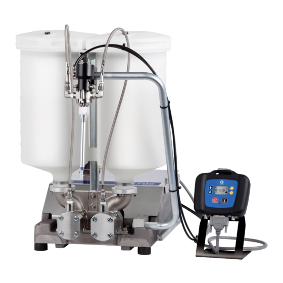
PR70e
Compact Benchtop Meter, Mix and Dispense System
Use for accurate metering, mixing and dispensing of two-component sealants and
adhesives in fixed ratios. Not for use with isocyanate catalyzed materials. For professional
use only.
Not approved for use in explosive atmospheres or hazardous locations.
Refer to Models, page 3, for maximum working pressures.
Important Safety Instructions
Read all warnings and instructions in this
manual. Save these instructions.
™
334135B
EN
Advertisement
Table of Contents

Related Manuals for Graco PR70e


Summary of Contents for Graco PR70e
- Page 1 Instructions ™ PR70e 334135B Compact Benchtop Meter, Mix and Dispense System Use for accurate metering, mixing and dispensing of two-component sealants and adhesives in fixed ratios. Not for use with isocyanate catalyzed materials. For professional use only. Not approved for use in explosive atmospheres or hazardous locations.
-
Page 2: Table Of Contents
Installation ....... 23 Graco Information ......70 Grounding . -
Page 3: Models
Models Models System MD2 Valve Air Motor Required Machine Maximum Maximum Ratio in. (cm) Line Operation Working Air Inlet Voltage Voltage Pressure Pressure psi (MPa, bar) psi (MPa, bar) 24S054 100-240 V 3 (7.6) 24S055 10:1 50/60 Hz, 24 VDC 3000 (21, 207) 100 (0.7, 7) 1 phase -... -
Page 4: Warnings
Warnings Warnings The following warnings are for the setup, use, grounding, maintenance, and repair of this equipment. The exclama- tion point symbol alerts you to a general warning and the hazard symbols refer to procedure-specific risks. When these symbols appear in the body of this manual or on warning labels, refer back to these Warnings. Product-specific hazard symbols and warnings not covered in this section may appear throughout the body of this manual where applicable. - Page 5 Warnings WARNING WARNING WARNING WARNING FIRE AND EXPLOSION HAZARD Flammable fumes, such as solvent and paint fumes, in work area can ignite or explode. To help prevent fire and explosion: • Use equipment only in well ventilated area. • Eliminate all ignition sources; such as pilot lights, cigarettes, portable electric lamps, and plastic drop cloths (potential static arc).
-
Page 6: Component Identification
Component Identification Component Identification Machine . 1: Machine Key: Power Switch Control Cable Air Inlet Ground Wire and Clamp System Air Pressure Relief Valve Air/Water Separator Assembly with Vented Ball Valve Local Control Module (LCM) (Not Supplied - 24R707) Air Pressure Regulator Footswitch Connection Drive Block 24V Power Supply... -
Page 7: Local Control Module (Lcm)
Component Identification Local Control Module (LCM) NOTICE To prevent damage to soft key buttons, do not press the buttons with sharp object such as pens, plastic cards, or fingernails. . 2: LCM Key: AA Dispense Request or “Go” key AE Status LED This key will dispense material and can not be disabled by Solid - System is ready and operational. -
Page 8: Lcm Screen Navigation
Component Identification LCM Screen Navigation For screen overview, refer to Appendix B - LCM Run Screen Overview and Appendix C - LCM Setup Screen Overview starting on page 62. Splash Screen Disable Mode Screen Maintenance Mode Shot Mode Screen Operator Mode Screen Run Screen Mode Selection Pro- gramming Screen... - Page 9 Component Identification 334135B...
-
Page 10: Recommended Parts
Recommended Parts Recommended Parts Dispense Valve Standard Dispense Valves, 255179 and 255181 See MD2 manual for parts information. Gun Mounted MD2 Valves, LC0120 and LC0122 901a 901b Assembly LC0120 Shown ti12440a Part Description Quantity LC0006 VALVE, assembly, 10:1, gun, electric (assembly LC0122 only) LC0004 VALVE, assembly, 1:1, gun, electric... - Page 11 Recommended Parts Lever Actuated MD2 Valves, LC0121 and LC0123 1101a 1101b 1103 1102 Assembly LC0121 Shown ti12441a Part Description Quantity 1101 LC0005 VALVE, assembly, 1:1, lever, electric (assembly LC0121 only) LC0007 VALVE, assembly, 10:1, lever, electric (assembly LC0123 only) 1101a 255249 LEVER, 2K dispense valve 1101b...
-
Page 12: Mixers
Recommended Parts Mixers 1301 1303 1302 Assembly LC0061 Shown ti12442a 334135B... - Page 13 Recommended Parts Reference Number and Description 1301 1302 1303 Mixer Mixer Shroud Sleeve Package Description Part No. (Quantity) Part No. (Quantity 1) Part No. (Quantity 1) LC0063 3/16 in. x 32 60/0206/50 (10) 94/0884-1/98 LC0077 3/16 in. x 32 60/0206/50 (50) LC0084 3/16 in.
-
Page 14: Applicator Mounting
Recommended Parts Applicator Mounting Mast Mount, Controls and MD2 Applicator, LC0292 Mast Mount, Controls only, LC0293 Quantity LC0292, BRACKET, LC0293, BRACKET, Part Description mounting, valve, HMI mounting, HMI 16P082 BASE, arm, mounting 16P409 BLOCK, mounting, front 16P550 BLOCK, mounting, rear 121194 SCREW 15K832... -
Page 15: Air Filter And Ball Valve, 24R707
Recommended Parts Air Filter and Ball Valve, 24R707 Part Description Quantity VALVE, vented 2 way 157350 ADAPTER 106148 FILTER, air, 3/8 NPT 155665 UNION, adapter NIPPLE, pipe High Temperature Grease, 115982 Footswitch, 255244 334135B... -
Page 16: Tanks
Recommended Parts Tanks 1 1/2 in. NPT Flanges, 24W417 8 Liter, Twin Polyethylene Tanks and Lids, 24W415 8 Liter, Twin Polyethylene Tanks and Lids, with Shut-Off Valves, 24W416 1025 1003 1007 1005 1003 1024 1011 1009 1007 1008 1023 1005 1025 1008 1006... - Page 17 Recommended Parts Quantity Part Description 24W415 24W416 24W417 1001 95/0223/00 O-RING 1002 120901 O-RING 1003 120902 SCREW, M5x40mm 1004 120904 SCREW, M5x18mm 1005 120905 NUT, hex, lock M5 1006 120906 NUT, hex, lock M8 x 1.25 1007 120907 WASHER, plain #10 1008 120908 WASHER, plain M8...
-
Page 18: Hose Packages
Recommended Parts Hose Packages Unheated, Non-Recirculating Hose 1404 1403 1401 1402 Assembly LC0801 Shown ti12446a Apply thread sealant tape to male npt threads before assembly. Reference Number and Description 1401 1402 1403 1404 Hose Package Description Hose Assembly 90 Deg Elbow Adapter Bushing LC0801... - Page 19 Recommended Parts 334135B...
-
Page 20: Piston Package
Recommended Parts Piston Package ti12438a Arrow on cylinder must point to the o-ring (606) on the right. Nylon Piston, Stainless Steel Metering Tube Assemblies Reference Number and Description 603† Piston Tube, Nylon Ring, support, Package pump Piston Washer piston Screw O-ring LC1080 LCC080... - Page 21 Recommended Parts UHMW Piston, Stainless Steel Metering Tube Assemblies Reference Number and Description 603† Piston Tube, UHMW Ring, support, Package pump Piston Washer piston Screw O-ring LC2160 LCC160 LCA160 LC2180 LCC180 LCA180 LC2200 LCC200 LCA200 LC2220 LCC220 LCA220 15M099 15K887 LC2240 LCC240 LCA240...
-
Page 22: Pump Tube Combination Information
Pump Tube Combination Information Pump Tube Combination Information Pump Tube Combination Information Power Factor Ratio Large Piston Small Piston Minimum Maximum 3 in. (X:1) (mm) (mm) Shot Size (cc) Shot Size (cc) Air Motor in. Air Motor 12.4 71.0 47.3 35.5 23.7 17.7... -
Page 23: Installation
Installation Installation Machine Installation Grounding Pump shaft, polyethylene (PE) tank lid, and PE tank lid gasket are coated with Krytox grease. Wear protective gloves and cover exposed skin to avoid possible skin irritation on contact. Read Krytox MSDS to know the The equipment must be grounded to reduce the risk of specific hazards, and follow manufacturer’s warnings. - Page 24 Installation Install Pump Tubes 7. Install the pump cap onto the assembly using the four bolts. Finger tighten the bolts, then torque the See Piston Package on page 20 and Nylon and bolts to 350 in-lb (40 N•m) in a crisscross pattern. UHMW Piston Replacement Kits on page 65 for kit numbers.
- Page 25 Installation Connect the Footswitch or External Device. Electrical Requirements 11. Connect AC power (100-240V, 50/60 Hz, sin- gle-phase) to the power supply provided. Connect the power supply to the machine as shown. Connect Pressurized Air Input 8. Install an air inlet bleeding ball valve and air filter kit (not provided with unit, but available as kit 24R707) at the 1/4 NPT female air inlet.
-
Page 26: Setup
Setup Setup Before setting up the machine, the user needs to be 3. Place a waste container under the dispense valve to familiar with the LCM screens. Refer to Appendix A - capture any dispensed material. LCM Icon Overview and Appendix B - LCM Run 4. - Page 27 Setup 10. Press the Enter button ( ) to accept the new 16. Press the Enter button ( ) to accept the value or value or press the Abort/Cancel button ( ) to press the Abort/Cancel button ( ) to keep the keep the previous value.
-
Page 28: Prime The Dispense Head
Setup Prime the Dispense Head 9. Select a large size shot. 10. Hold a waste container at the end of the dispense head and press the Dispense Request button ) or the footswitch. NOTICE 11. Repeat the previous step until no air comes out of If the dispense head is not primed, chemical cross- the dispense valve. -
Page 29: Phasing Adjustment
Setup Phasing Adjustment Adjust Dispense Quantity 6. Press the Phasing shot button ( ) to enter phasing mode. 7. Press the Dispense Request button ( ) or the footswitch to dispense a very small amount of mate- rial. 8. Adjust the displayed percentage if more than a cou- ple drops of either material was dispensed or if no material was dispensed from both sides. - Page 30 Setup Adjust Phasing Hold the phase adjustment screw (003) sta- tionary with a 13 mm wrench. Use a 7 mm wrench to turn the piston shaft (001) counterclockwise 1/4 turn or less to move the A piston forward. NOTE: It is highly recommended that all of the phasing adjustment be done to one side or the other;...
-
Page 31: Adjust Dispense Valve Snuff Back
Setup Adjust Dispense Valve Snuff Back At the end of a shot, a small amount of material is drawn back into the static mixer to prevent extra material from being dispensed. If too much snuff back occurs, air will enter the static mixer and can travel up into the dispense valve. -
Page 32: Adjust Open Dispense Valve (Odv) Timing
Setup Adjust Open Dispense If a high positive number is entered for ODV timing, such as 6.0 mm, the dispense valve may not open resulting in Valve (ODV) Timing the fluid stalling against the dispense valve. The fluid in the hose lines will remain under pressure until the piston is manually retracted using the Manual screen, see Operator Mode Screen. -
Page 33: Operation
Operation Operation Startup Pressure Relief Procedure Follow the Pressure Relief Procedure whenever you see this symbol. 1. Locate the power switch at rear of machine and turn the power on. The display module will automatically turn on and begin to load. 2. -
Page 34: Shutdown
Operation Shutdown If the machine is to remain idle for an extended period of time, perform the following steps. 1. If installed, remove static mixer from the end of the dispense valve. 2. Place a container below the dispense valve and activate a small shot to flush mixed material out of the valve. -
Page 35: Maintenance
Maintenance Maintenance Schedule Action Schedule Procedure Check Water/Air Separator Daily before use 1. Check water/air separator for water. (Not provided) 2. Open valve at base of water/air separator to purge water. Check Desiccant Dryer (only Daily before use 1. Check the color of the desiccant installed if chemical is moisture 2. -
Page 36: Install Upgrade Token
7. Replace the token access panel. 8. Restore power to the module. 9. Verify new software versions on the Setup Screen Password Set/Clear Screen screen. Refer to PKE 2903 found at www.graco.com for the latest software version by utilizing the search box. 334135B... -
Page 37: Troubleshooting
Troubleshooting Troubleshooting Before starting any troubleshooting procedures, perform 3. Allow the machine to cool if the machine has a heat the following procedure. control option. Try the recommended solutions in the order given for 1. Relieve pressure. See Pressure Relief Procedure, each problem to avoid unnecessary repairs. - Page 38 Troubleshooting Problem Cause Solution Machine dispensing off ratio One tank is empty Check tank levels. Add material if necessary. Tank ball valve closed Open tank ball valve. Prime machine. Machine out of phase Re-phase machine. Check valve malfunction Remove check valve; clean or replace as necessary.
-
Page 39: Lcm Error Codes
Troubleshooting LCM Error Codes If an error condition exists, the front Panel LED will blink the number of times corresponding to the error code number, pause, then repeat. After the user acknowledges the generated error screen, the error number will appear on the bot- tom left-hand side of the main run screen, and the described blink sequence will continue. -
Page 40: Repair
Repair Repair HydraCheck Kit Installation, 24W336 Be sure that system pressure is relieved and disabled before proceeding. . 11: HydraCheck Installation - Fixed Ratio Base NOTE: The HydraCheck kit is intended to be used with Install HydraCheck Shock low viscosity materials to minimize splashing. It is not 6. - Page 41 Repair Install Adjustment Screw/Cap 9. Loosely install hex nut and adjustment cap onto the air cylinder shaft. Adjust the Adjustment Screw/Cap 10. Push the drive block forward until resistance is felt when it engages the cylinder. Make sure the resis- tance is not due to shock absorber contact with the adjustment screw or adjustment cap.
-
Page 42: Air Cylinder Rebuild Instructions
Repair Air Cylinder Rebuild Instructions Finger tighten all (4) bolts prior to wrench tightening. For wrench tightening, turn each bolt 1/4 turn in a cross pattern until all (4) bolts are torqued to 350 in-lb (40 N•m). Torque to 1200 in-lb (136 N•m). Coat all sliding surfaces with lubricant, part 115982. - Page 43 Repair 7. Use an open-end wrench to remove all hex nuts the bolts to 350 in-lb (39.5 N•m) in a crisscross pat- connecting the piston rod to the drive block. tern. 8. Remove the four screws that attach the cylinder rod end block to the frame.
-
Page 44: Rear Pump Rebuild Instructions
Repair Rear Pump Rebuild Instructions The pump shaft is installed coated with Krytox grease. Wear protective gloves and cover exposed skin to avoid possible skin irritation on contact. Read Krytox MSDS to know the specifc hazards, and follow manufacturer’s warnings. Torque to 350 in-lb (40 N•m). - Page 45 Repair 8. Disconnect the pump shaft from the drive block. 17. Apply one layer of thin masking tape over the male threads of the pump shaft that mates with the drive a. Loosen the shaft locking nut. block. This will prevent the threads from damaging the seal.
-
Page 46: Piston/Cylinder Replacement Kit Installation
Repair Piston/Cylinder Replacement Kit 9. Remove the piston and any front or rear washers from the pump shaft. Installation 10. Clean and inspect the washers. Install Cylinder 11. Install the new piston and any front or rear washers. NOTE: See Piston Package on page 20 and Nylon 12. -
Page 47: Check Valve Rebuild Kit Installation
Repair Check Valve Rebuild Kit 7. Remove the check valve housing from the pump endcap by loosening the housing with a wrench. Installation 8. Remove the existing check valve from the housing by inserting a screwdriver or dowel rod into the female threaded end of the check valve housing. -
Page 48: Parts
Parts Parts Fixed Ratio Base Torque to 140 in-lb (15.8 N•m). Torque to 350 in-lb (39.5 N•m). Torque to 1200 in-lb (135 N•m). Torque to 85 in-lb (9.6 N•m). . 14 334135B... - Page 49 Parts . 15 Quantity 24V935, PUMP, 24V936, PUMP, Part Description assembly, 3.0 assembly, 4.5 24S053 PUMP, sub-assembly 120913 SCREW 120919 NUT, hex LC0107 BLOCK, assembly, drive 121166 SCREW 24V933 MOTOR, air, 3.0 24V934 MOTOR, air, 4.5 LC0290 FRAME, sub, assembly 121167 SCREW 120885...
-
Page 50: Pump Sub-Assembly, 24S053
Parts Pump Sub-Assembly, 24S053 The pump shaft is installed with Krytox grease. Contact with Krytox grease can lead to flu-like symptoms. The MSDS for this material is available upon request. Torque to 350 in-lb (40 N•m). Lubricate shaft with Krytox grease prior to insertion into bearing. Apply thread sealant to threads. - Page 51 Parts Part Description Quantity 101* 106258 PACKING, o-ring 108712 NUT, hex 103* 120887 SEAL, posipak, 3/8x5/8, UHMWPE 104* 120890 RING, retaining 120913 SCREW 17B389 SCREW, cap, hex head 15K786 HOUSING, pump 17B295 CAP, end, pump 15K803 COLLAR 15K804 HOUSING, bearing, seal 15K824 ROD, piston 15K828...
-
Page 52: Fixed Ratio Drive Block Assembly, Lc0107
Parts Fixed Ratio Drive Block Assembly, LC0107 Apply grease (part 115982) to all internal parts. Tighten retaining nut until alignment rod (202) cannot be moved. Loosen retaining nut until alignment rod can move side-to-side with no in-and-out movement. Torque to 64 in-lb (7.2 N•m). . -
Page 53: Air Cylinder, 24V933 And 24V934
Parts Air Cylinder, 24V933 and 24V934 NOTICE The four long screws (303) that attach the two drive blocks (309,310) must be tightened in a crisscross pattern. Failure to do so may result in air cylinder damage. Refer to page 42 for rebuild instructions. Finger tighten all (4) bolts prior to wrench tightening. -
Page 54: Fixed Ratio Frame Sub-Assembly, Lc0290
Parts Fixed Ratio Frame Sub-Assembly, LC0290 Torque screws to 85 in-lb (9.6 N•m). Lubricate linear slide. . 20 Part Description Quantity 120599 PIN, dowel FRAME, base, machined LC0234 SENSOR, assembly 120918 BEARING, linear, slide 120886 SCREW 17B318 PAD, rubber, anti-vibration 334135B... - Page 55 Parts UHMW Piston, Ceramic Metering Tube Assemblies NOTE: The UHMW piston, ceramic metering tube assemblies contain a carbide ball. This ball replaces the standard check valve ball in pump assembly LC0112. If a UHMW piston, ceramic metering tube assembly needs to be installed, replace the original ball in pump assem- bly LC0112 with the ball included with the pump pack- age.
-
Page 56: Schematics
Schematics Schematics Electrical Schematics . 21: Electrical Schematic 334135B... - Page 57 Schematics . 22: Electrical Schematic 334135B...
-
Page 58: Pneumatic Schematic
Schematics DB25 Pin Function DB25 Pin Number Pin Function Description Digital In 1 Footswitch/Shot Request Input Analog In 1 Position Sensor Analog Input Source Digital Out 1 Dispense Valve (DV) Open Command Source Digital Out 2 Pump Retract Command Source Digital Out 3 Pump Extend Command V_CAN (+24V) LCM and Module Power Feed... - Page 59 Schematics 334135B...
-
Page 60: Appendix A - Lcm Icon Overview
Appendix A - LCM Icon Overview Appendix A - LCM Icon Overview Icon Label Description Power On When the corresponding soft key is pressed, the PR70 will exit disable mode and enter the last mode used (Shot or manual) and display the corresponding mode on the home run screen. - Page 61 Appendix A - LCM Icon Overview Icon Label Description Phasing Shot Graphic used to indicate the user wants to arm the machine to allow phasing shots when the user presses the dispense key, or presses the optional machine footswitch input. Phasing Shot Adjust Graphic used to indicate the user wants to adjust the position into the metering tube where the pump reverses during the phasing shot dispense.
-
Page 62: Appendix B - Lcm Run Screen Overview
Appendix B - LCM Run Screen Overview Appendix B - LCM Run Screen Overview Splash Screen Operator Mode Screen This screen is activated during a boot up condition. The This mode is the dispensing mode where the dispense splash screen will only be present approximately for five amount is dictated by the duration the user is requesting seconds. - Page 63 Graco alarm bell, and a soft key prompting the needs to press the dispense request key to issue the user to acknowledge the condition. Once the condition request.
-
Page 64: Appendix C - Lcm Setup Screen Overview
Appendix C - LCM Setup Screen Overview Appendix C - LCM Setup Screen Overview Password Entry Screen Open Dispense Valve Position Calibration Screen If a password is programmed into the LCM, the user will be prompted to enter a password. If no password has This screen is to set or view the position with reference been entered (all 0's on the password set/ clear setup to the metering tube entrance where the dispense valve... -
Page 65: Kits
Kits Kits Nylon and UHMW Piston Replacement Kits Piston Sizes 080-119 Piston Sizes 160-960 Piston Sizes 120-159 When ordering a piston replacement kit, the following Part Description Quantity intelligent part numbering system applies for Nylon PISTON based pistons. SCREW O-RING LCF - Piston Size (mm2) When ordering a UHMW replacement kit, the following numbering applies:... -
Page 66: Recommended Spare Parts
Kits Recommended Spare Parts PR70E Part Description Quantity LC0091 3.0 in. (7.6 cm) Air Cylinder Rebuild Kit LC0092 4.5 in. (11.4 cm) Air Cylinder Rebuild Kit LC0093 Stainless Steel Ball Check Valve Rebuild Kit LC0318 Carbide Ball Check Valve Rebuild Kit... -
Page 67: Dimensions
Dimensions Dimensions 15.5 in. (40 cm) 9.0 in. (23 cm) 25.1 in. (65 cm) 27.9 in. (71 cm) 334135B... - Page 68 Dimensions 334135B...
-
Page 69: Technical Data
Technical Data Technical Data PR70e Metric Metering Pump Effective Area 0.124 to 1.49 in. per side 80 to 960 mm per side Small Air Cylinder Effective Area 7.07 in. 4560 mm Large Air Cylinder Effective Area 15.9 in. 10260 mm Maximum Stroke Length 38.1 mm... -
Page 70: Graco Standard Warranty
With the exception of any special, extended, or limited warranty published by Graco, Graco will, for a period of twelve months from the date of sale, repair or replace any part of the equipment determined by Graco to be defective.
Need help?
Do you have a question about the PR70e and is the answer not in the manual?
Questions and answers