Icom IC-9700 Basic Manual
Vhf/uhf all mode transceiver
Hide thumbs
Also See for IC-9700:
- Advanced manual (173 pages) ,
- Service manual addendum (163 pages) ,
- Service manual (93 pages)
Table of Contents
Advertisement
Quick Links
Advertisement
Table of Contents

Subscribe to Our Youtube Channel
Related Manuals for Icom IC-9700


Summary of Contents for Icom IC-9700
- Page 1 BASIC MANUAL VHF/UHF ALL MODE TRANSCEIVER |9700...
- Page 2 VHF/UHF ALL MODE TRANSCEIVER with Icom’s state of the art technology and craftsmanship. With proper care, this product should provide you with years of trouble-free operation. We appreciate you making the IC-9700 your transceiver of choice, and hope you agree with Icom’s philosophy of “technology first.”...
- Page 3 TRADEMARKS Icom is not responsible for the destruction, damage Icom, Icom Inc. and the Icom logo are registered to, or performance of any Icom or non-Icom trademarks of Icom Incorporated (Japan) in Japan, the equipment, if the malfunction is because of: United States, the United Kingdom, Germany, France, •...
- Page 4 The following manuals or Guide for this transceiver In the Advanced manual or Basic manual, the touch are published at the following internet address: operation is described as shown below, with the beep http://www.icom.co.jp/world/support/ tone ON. • Advanced Manual (English) Instructions for advanced operations in English.
- Page 5 ABOUT THE INSTRUCTIONS The Advanced and Basic manuals are described in Detailed instruction the following manner. 1. Push MENU “ ” (Quotation marks): Used to indicate icons, setting items, and screen titles displayed on the screen. The screen titles are also written in uppercase letters. (Example: FUNCTION screen) [ ] (brackets): Push...
-
Page 6: Table Of Contents
TABLE OF CONTENTS IMPORTANT ............... i Setting the frequency ........3-4 FEATURES ..............i D Using the Main Dial ........3-4 EXPLICIT DEFINITIONS ..........i D About the Tuning Step function ....3-4 SUPPLIED ACCESSORIES ........i D Changing the Tuning Step ......3-4 FCC INFORMATION ..........ii D About the 1 MHz Step Tuning function .. - Page 7 Operating CW ..........4-10 CLOCK ������������������������������������������������������������� 9-1 D Setting the CW pitch control ....4-10 Setting the date and time ......... 9-1 D Setting the key speed ......4-10 D Setting the date .......... 9-1 D Using the Break-in function ...... 4-11 D Setting the current time ......
- Page 8 R WARNING! NEVER remove the fuse holder on the DC level. Otherwise, the linear amplifier will be damaged. power cable. Excessive current caused by a short could CAUTION: DO NOT use non-Icom microphones. Other cause a fire or damage the transceiver. microphones have different pin assignments, and may R WARNING! NEVER let metal, wire or other objects damage the transceiver.
-
Page 9: Panel Description ������������������������������������
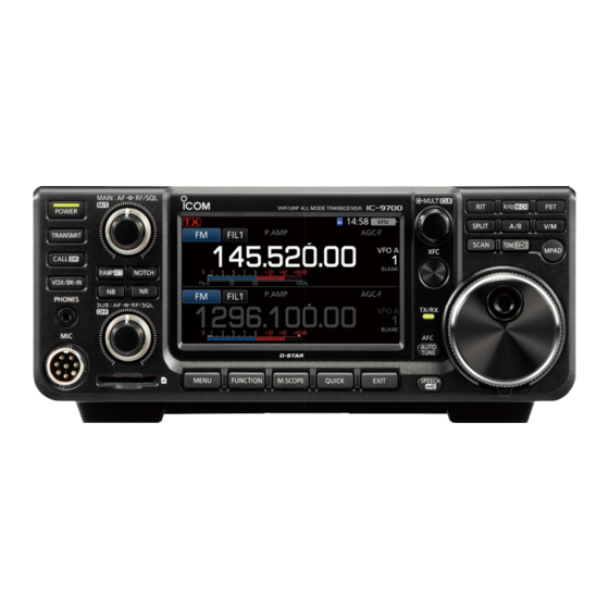
PANEL DESCRIPTION Front panel This section describes the keys, controls and dials that you use to operate the IC-9700. Refer to the pages posted beside each key, control, or dial for details. o VOLUME CONTROL (p� 3-1) RF/SQL L The upper control is for the Main band, and the lower control is for the Sub band. - Page 10 PANEL DESCRIPTION Front panel (Continued) @6 A/B KEY (p� 3-1) Switches between VFO A and VFO B, or copies the selected VFO’s frequency, mode and filter settings to the other VFO. @7 PASSBAND TUNING CONTROL KEY (p� 4-3) Enables to adjust the Passband Tuning MULTI Control (PBT).
-
Page 11: Rear Panel
PANEL DESCRIPTION Rear panel q ANTENNA CONNECTOR [144 MHz ANT] (p� 2-2) !1 GROUND TERMINAL [GND] (p� 2-1) Connects to a 50 Ω PL-259 coax connector. Connects to ground to prevent electrical shocks, TVI, BCI and other problems. w ETHERNET CONNECTOR [LAN] Connects to a PC network through a LAN. -
Page 12: Touch Screen Display
PANEL DESCRIPTION Touch screen display q LMT ICON i SD CARD ICON (p� 6-1) Displayed if the power amplifi er temperature Displayed when an SD card is inserted, and blinks becomes extremely high, and the Protection while accessing the SD card. function is activated after transmitting continuously o CLOCK READOUT (p�... - Page 13 PANEL DESCRIPTION !9 OVF ICON @6 AFC/ ICON (p� 8-5) Displayed when an excessively strong signal is “ ” is displayed while the Auto Frequency received. Control (AFC) is ON. “ ” is displayed while the 1/4 Tuning function is @0 PREAMPLIFIER/ATTENUATOR ICONS ON.
-
Page 14: D Function Screen
PANEL DESCRIPTION Touch panel (Continued) D FUNCTION screen D MENU screen Function name Selected value Lights blue when active z Push to open the FUNCTION screen in z Push to open the MENU screen on the FUNCTION MENU the selected mode. selected band. - Page 15 PANEL DESCRIPTION Multi-function dial D Multi-function menus When the Multi-function menu is closed, MULTI be enabled to adjust functions that are either on the Rotate upper right three keys or in the Multi-function menus. The function is displayed in the upper right edge of the screen.
-
Page 16: Keyboard Entering And Editing
PANEL DESCRIPTION Keyboard entering and editing D Entering and editing characters You can enter and edit the items in the following table. Maximum Menu Category Item Selectable characters characters My Station My Call Sign (DV)/(DD) A to Z, 0 to 9, (space), / TX Message (DV) A to Z, a to z, 0 to 9, (space), ˽... -
Page 17: D Keyboard Types
PANEL DESCRIPTION D Keyboard types You can select the Full Keyboard or Tenkey pad in “Keyboard Type” on the FUNCTION screen. (p. 8-4) » SET > Function > Keyboard Type MENU L You can also temporarily switch in the QUICK MENU by pushing QUICK L You can select the full keyboard layout in “Full Keyboard... -
Page 18: D Entering And Editing Example
PANEL DESCRIPTION Keypad entering and editing (Continued) D Entering and editing example Entering “DX spot 1” in the Memory channel 2 1. Open the MEMORY screen. 9. Touch [ab]. » MEMORY MENU 2. Touch memory channel 2 for 1 second. You can also open the QUICK MENU... -
Page 19: Installation And Connections �����������
L We recommend using Icom’s optional PS-126 the DC power cable. (DC 13.8 V/25 A) power supply, when available. L When connecting a non-Icom DC power cable, the transceiver needs: • DC 13.8 V (Capacity: At least 18 Amps) • A power supply with an over current protective line, and low voltage fluctuation or ripple. -
Page 20: When First Applying Power
Using the VFO mode Adjusting the volume level Rotate (inner) to adjust the volume level. The IC-9700 has 2 Variable Frequency Oscillators RF/SQL (VFO), “A” and “B.” Having 2 VFOs is convenient to quickly select 2 frequencies, or for split frequency operation (p. -
Page 21: Dualwatch Operation
Dualwatch operation Selecting the Main and Sub bands Dualwatch simultaneously monitors two frequencies. The IC-9700 has 2 identical receivers, Main and Sub. The IC-9700 has 2 independent receiver circuits, the The Main band is displayed on the upper half of the Main and Sub bands, so that you can use Dualwatch screen, and the Sub band is displayed on the lower half. -
Page 22: Selecting The Operating Band
BASIC OPERATION Selecting the operating band Selecting the operating mode Do the following steps to change the operating band. You can select between the SSB (LSB/USB), SSB Also, the band stacking register provides 3 memories data (LSB-DATA/USB-DATA), CW, CW reverse, RTTY, for each band key to store frequencies and operating RTTY reverse, AM, AM data (AM-DATA), FM, FM data modes. -
Page 23: Setting The Frequency
BASIC OPERATION Setting the frequency D About the 1 MHz Step Tuning function D Using the Main Dial 1. Select the desired operating band. (p. 3-3) You can use the maximum tuning step of 1 MHz. (Example: 145 MHz) Touch the MHz digits for 1 second to turn the MHz 2. -
Page 24: D About The 1/4 Tuning Function
BASIC OPERATION Setting the frequency (Continued) D About the 1/4 Tuning function D Directly entering a frequency Mode: SSB-D/CW/RTTY You can set the frequency without rotating MAIN DIAL With the Tuning Function OFF, turn ON the 1⁄4 Tuning by directly entering it on the keypad. function to reduce the tuning speed to 1⁄4 of the Entering the operating frequency normal speed, for finer tuning. -
Page 25: D Band Edge Beep
BASIC OPERATION Setting the frequency (Continued) Entering the Split Frequency Offset Selecting a Memory channel by number 1. Touch the MHz digits. (Example: 146) 1. Touch to select the Memory mode. 2. Touch the MHz digits. (Example: 146) • Opens the BAND STACKING REGISTER screen. •... -
Page 26: D Entering A Band Edge
BASIC OPERATION Setting the frequency (Continued) D Entering a Band Edge 3. Edit the lower band edge frequency, then touch [ENT]. (Example: 430.1) When “ON (User)” or “ON (User) & TX Limit” is Entry example: selected on the “Band Edge Beep” screen, you can [•], [1], [ENT] enter a total of 30 band edge frequency pairs. - Page 27 BASIC OPERATION Setting the frequency D Entering a Band Edge (Continued) Deleting a Band Edge Entering a new Band Edge To enter a new band edge, first you must delete a After you delete or edit the preset band edges, you preset band edge.
- Page 28 BASIC OPERATION Setting the frequency D Entering a Band Edge (Continued) Inserting a Band Edge Resetting all band edges to presets After you delete or edit the preset band edges, follow The steps below will reset all the band edges to their the steps below to insert a band edge.
-
Page 29: Rf Gain And Sql Level
BASIC OPERATION Adjusting the transmit output RF gain and SQL level power Rotate (outer) to adjust the RF gain and RF/SQL Before transmitting, monitor your selected operating SQL level. frequency to make sure you do not cause interference to other By default, rotating left (when set to the 12 o’clock stations on the same frequency. -
Page 30: Meter Display
BASIC OPERATION Meter display Adjusting the microphone gain D Meter display selection Adjust the microphone gain as described below. 1. Set the operating band and mode to SSB, AM, FM You can display one of the 6 different transmit or DV. (p. 3-3) parameters (Po, SWR, ALC, COMP, VD and ID) for your convenience. -
Page 31: Receiving And Transmitting �����������������
RECEIVING AND TRANSMITTING Preamplifiers RIT function The preamp amplifies received signals in the receiver front The RIT (Receive Increment Tuning) function compensates end to improve the signal-to-noise ratio and sensitivity. A for differences in frequencies of other stations. preamp is used when receiving weak signals. The function shifts the receive frequency up to L Each band memorizes the Preamplifier setting. -
Page 32: Agc Function Control
RECEIVING AND TRANSMITTING AGC function control D Setting the AGC time constant SSB, CW, RTTY and AM modes You can set the preset AGC time constant to the The AGC (Automatic Gain Control) controls receiver desired value. gain to produce a constant audio output level, even when the received signal strength greatly varies. -
Page 33: Using The Digital Twin Pbt
RECEIVING AND TRANSMITTING Using the Digital Twin PBT SSB, CW, RTTY and AM modes Information • Touch the filter icon for 1 second to display the current To reject interference, the Digital Twin PBT passband width and shift value. (Passband Tuning) narrows the IF passband width •... -
Page 34: Selecting The If Filter
SSB, CW, RTTY and AM modes Mode IF filter Selectable range (steps) The IC-9700 has 3 IF filter passband widths for each FIL 1 (3.0 kHz) 50 Hz to 500 Hz (50 Hz)/ mode, and you can select them on the FILTER screen. -
Page 35: Noise Blanker
RECEIVING AND TRANSMITTING Noise Blanker SSB, CW, RTTY and AM modes NB is OFF NB is ON (Effective) The Noise blanker eliminates pulse-type noise such Pulse-type Noise removed NB LEVEL noise as the noise from car ignitions. Desired signal Desired signal Push to turn the Noise Blanker ON or OFF. -
Page 36: Noise Reduction
SSB, CW, RTTY, AM, FM and DV modes SSB, CW, RTTY, AM and FM modes The Noise Reduction function reduces random noise The IC-9700 has Auto Notch and Manual Notch components and enhances signal audio. functions. Auto Notch automatically attenuates beat tones,... -
Page 37: Monitor Function
RECEIVING AND TRANSMITTING Monitor function IP Plus function The IP Plus function improves the Intermodulation The Monitor function enables you to monitor your Distortion (IMD) quality by exerting the direct sampling transmit audio. Use this function to check the system performance. voice characteristics while adjusting transmit audio This function optimizes the Analog/Digital Converter parameters. -
Page 38: Setting The Speech Compressor
RECEIVING AND TRANSMITTING Setting the Speech Compressor SSB mode D Using the Speech Compressor function 1. Touch the Multi-function meter again to display The Speech Compressor increases the average RF the COMP meter. output power, improving readability at the receiving 2. -
Page 39: Split Frequency Operation
RECEIVING AND TRANSMITTING Split frequency operation Split frequency operation enables you to transmit and There are 2 ways to use Split frequency operation. receive on different frequencies in the same band. • Use the Quick Split function • Use the receive and transmit frequencies set to VFO A and VFO B. -
Page 40: Split Lock Function
RECEIVING AND TRANSMITTING Split Lock function Operating CW D Setting the CW pitch control To prevent accidentally changing the receive frequency by releasing while rotating MAIN DIAL You can set the received CW audio pitch and the CW use the Split Lock function. Using both this function side tone to suit your preference without changing the and the Dial Lock function enables you to change only operating frequency. -
Page 41: D Using The Break-In Function
In the Full Break-in mode, the transceiver automatically switch between transmit and receive automatically transmits while keying down, and then when keying. The IC-9700 is capable of Semi Break-in immediately returns to receive after keying up. and Full break-in modes. -
Page 42: D About The Electronic Keyer Function
RECEIVING AND TRANSMITTING Operating CW (Continued) D About the electronic Keyer function You can set the Keyer Memory function settings, paddle polarity settings, and so on of the Electronic Keyer. 1. Select the CW mode. 2. Open the KEYER screen. EDIT KEYER MEMORY edit menu »... -
Page 43: Scope Operation ���������������������������������������
SCOPE OPERATION Spectrum scope screen D Using the Spectrum Scope The spectrum scope enables you to display the activity on the selected band, as well as the relative Display the SPECTRUM SCOPE screen. strengths of various signals. » SCOPE MENU The transceiver has two spectrum scope modes, the MAIN/SUB band icon* Center mode and the Fixed mode. -
Page 44: D Center Mode
SCOPE OPERATION Spectrum scope screen (Continue) D Center mode D Touch screen operation Displays signals around the operating frequency When you touch the FFT scope zone or the waterfall within the selected span. The operating frequency is zone in the SPECTRUM SCOPE screen, the area always displayed in the center of the screen. -
Page 45: Options
SCOPE OPERATION Audio scope screen D AUDIO SCOPE SET screen This audio scope enables you to display the received signal’s frequency component on the FFT scope, and This screen is used to set the FFT scope waveform its waveform components on the Oscilloscope. The type, color, Waterfall display and oscilloscope FFT scope also has an waterfall. -
Page 46: About The Sd Cards
In that case, use a new one. We recommend that you make a separate backup file of the important data onto your PC. • Icom will not be responsible for any damage caused by data corruption on an SD card. Saving data 3. -
Page 47: Unmounting
SD CARD Unmounting Saving the setting data Before you remove a card when the transceiver is ON, The Memory channels and the transceiver’s settings be sure to electrically unmount it, as shown below. can be saved onto an SD card. Otherwise the data may be corrupted or deleted. -
Page 48: Loading The Saved Data
7. Touch [YES]. • After the loading ends, “COMPLETED! Restart the IC-9700.” is displayed. L When you select “REF Adjust” in step 4, “The new "REF Adjust" setting will be saved” is displayed. 8. Turn OFF the transceiver power, then turn it ON again to restart the transceiver. -
Page 49: Deleting A Data File
SD CARD Deleting a data file Displaying the card information Follow the steps below to delete the files you no You can display the SD card capacity, and the time longer need on the SD card. remaining for voice recording. 1. -
Page 50: Importing Or Exporting A Csv Format File
SD CARD Importing or Exporting a CSV format file Please read this section before importing or exporting NOTE: a Comma Separated Values (CSV) format file from the • Before importing, make a backup file of all the SD card. transceiver’s data to the SD card in case of data You can import or export the following data: loss. -
Page 51: D Exporting
SD CARD Importing or Exporting a CSV format file (Continued) D Exporting 1. Open the IMPORT/EXPORT screen. 5. To save the file with the displayed name, touch [ENT]. » SET > SD Card > Import/Export MENU 2. Touch “Export.” L If you want to change the name, delete the name and reenter it, and then touch [ENT]. -
Page 52: About The Sd Card Folders
You can easily restore data with a backup file, even if The folder in the SD card contains the following. the setting data in the SD card is accidentally deleted. • IC-9700 folder The folders created in the IC-9700 are contained in this folder. IC-9700 Capture GpsMemory •... -
Page 53: Satellite Communication ����������������������
SATELLITE COMMUNICATION D Setting the satellite VFO Satellite communications outline 1. Touch [MAIN]. • The Main band is selected. Both Satellite Mode B (435 MHz uplink, 145 MHz downlink), Mode J (145 MHz uplink, 435 MHz downlink) and Mode L (1270 MHz uplink, 435 MHz downlink) can be operated. -
Page 54: Loop Test Procedure
SATELLITE COMMUNICATION Loop test procedure Decide on a usable satellite, and point your antenna About the Loop test: towards it. Loop test is a method to confirm the communication status L Monitored audio may cause howling. Using headphones between your station and the satellite. By transmitting your is recommended. -
Page 55: Satellite Operation
SATELLITE COMMUNICATION Satellite operation Satellite memories When your own signal can be received with a loop The IC-9700 has 99 satellite memories to store both test, satellite communication can be performed. uplink and downlink frequencies, operating modes and other data. -
Page 56: Set Mode Description
SET MODE Set mode description You can use the Set mode to set infrequently changed TIP: The Set mode is constructed in a tree structure. values or function settings. You may go to the next tree level, or go back a level, depending on the selected item. -
Page 57: Tone Control/Tbw
SET MODE Tone Control/TBW Function » SET > Tone Control/TBW > RX » SET > Function MENU MENU SSB, AM, FM, DV, CW, RTTY Beep Level (Default: 50%) RX HPF/LPF (Default: – – – – – – – – –) Sets the beep output level. - Page 58 L If an external equipment’s rise time is slower than that SSB, CW and RTTY modes. of the IC-9700, a reflected wave is produced and it may Functions as a squelch control in the AM, damage the IC-9700 or the external device. To prevent this, set the appropriate delay time so that no reflected FM, DV, and DD modes.
- Page 59 SET MODE S-Level SPEECH (Default: ON) » SET > Function > SPLIT MENU Turns the S-meter level announcement ON or OFF. SPLIT LOCK (Default: OFF) • OFF: The operating mode and the operating frequency are announced when you push Turns the Split Lock function ON or OFF. SPEECH •...
-
Page 60: My Station
SET MODE Screen Capture [POWER] Switch (Default: OFF) Function (Continued) Assigns the Screen Capture function to POWER • OFF: does not act as the Screen Capture POWER » SET > Function key. MENU • ON: acts as the Screen Capture key. POWER AFC Limit (Default: ON) -
Page 61: Dv/Dd Set
SET MODE » SET > DV/DD Set > DV Fast Data DV/DD Set MENU Fast Data (Default: OFF) » SET > DV/DD Set MENU Selects whether or not to use the DV Fast Data function for data communication in the DV mode. Standby Beep (Default: ON (to me:Alarm/High Tone) The DV Fast Data function uses the data and the audio frames to send data approximately 3.5 times... - Page 62 SET MODE EMR AF Level (Default: 50%) DV/DD Set (Continued) Set the audio output level when an EMR communication mode signal is received. » SET > DD Set When an EMR signal is received, the audio will be MENU heard at the programmed level, or the transceiver’s Digital Repeater Set (Default: ON) audio level, whichever is higher.
-
Page 63: Qso/Rx Log
* The default value may differ, depending on the transceiver version. TIP: • The folder name is automatically created, as [IC-9700\QsoLog]. • The file name is automatically created, as shown in the example below: Log start date and time: 1st January 2019 15:30:00 File name: 20190101_153000.csv... - Page 64 SET MODE QSO/RX Log (Continued) The call log contents are shown below: Contents Example Descriptions TX/RX Transmission and reception Date 1/1/2019 13:51:48 1/1/2019 13:51:48 Date and time the call was started. Main Frequency 438.010000 438.010000 Operating frequency of the MAIN band Operating mode of the MAIN band Main Mode ( USB/USB-D/LSB/LSB-D/CW/CW-R/RTTY/RTTY-R/AM/...
- Page 65 Barometric (unit: hPa) Records to one decimal place. Humidity Humidity (unit: %) GPS Time Stamp 12:00:00 Time data that the caller station acquires the position data Caller is “NMEA”: Records the GPS message GPS Message Osaka City/IC-9700 Caller is “D-PRS: Records the D-PRS comment 8-10...
-
Page 66: Connectors
SET MODE » SET > Connectors > ACC AF/IF Output Connectors MENU AF/SQL Output Select (Default: MAIN) » SET > Connectors > External P�AMP MENU Selects the audio and squelch signals to output from the [ACC] (DIN 8-pin) socket in the MAIN/SUB bands. 144M (Default: OFF) •... - Page 67 SET MODE » SET > Connectors > USB AF/IF Output » SET > Connectors > MOD Input MENU MENU Output Select (Default: AF) ACC MOD Level (Default: 50%) USB MOD Level (Default: 50%) Selects the signal output from [USB]. LAN MOD Level (Default: 50%) •...
- Page 68 The transceiver transmits after a few seconds Selects the CI-V data transfer rate when remotely have passed, to prevent unintentional controlling the IC-9700 through the [USB] CI-V port. transmission. L When “Auto” is selected, the baud rate is automatically L If you change this setting to “OFF,” update the transceiver’s USB set according to the data rate of the external device.
-
Page 69: Network
Network Name L It is valid when “USB (B) Function” is set to “OFF” or “DV If you are operating the IC-9700 using the optional Data,” and “DATA Function” is set to “GPS/Weather.” RS-BA1, enter a network name of up to 15 characters. -
Page 70: Display
(Default: IC-9700) L When “Normal,” “RX Hold,” or “Hold” is selected, and if Sets the IC-9700’s name of up to 16 characters that the call sign and name of the caller station is programmed is displayed in the remote control software, when you in your memory, the programmed name is displayed after remotely control the IC-9700. - Page 71 SET MODE RX Position Indicator (Default: ON) TX Call Sign Display (Default: Your Call Sign) Selects whether or not to display the indicator when Select whether or not to display My or Your call sign the position data is included in the signal received in while transmitting the DV mode.
- Page 72 English by doing a partial reset of Set the system language of the transceiver. the IC-9700 CPU. A partial reset will not clear your • English: The system language of the transceiver call sign databases.
-
Page 73: Time Set
MENU NOTE: The backup battery for the internal clock Import The IC-9700 has a rechargeable Lithium battery to backup Import the UR call sign, repeater list or GPS memory the internal clock. If you connect the transceiver to a data in the CSV format file. -
Page 74: Others
MENU Clone Mode Selects to enter the clone mode to read or write the CS-9700 data from or to the PC. LRestart the IC-9700 to cancel the clone mode. » SET > Others MENU Touch Screen Calibration Touch to adjust the touch screen. -
Page 75: Clock �������������������������������������������������������������
CLOCK Setting the date and time NTP function The NTP (Network Time Protocol) function synchronizes D Setting the date the internal clock with the time management server. 1. Open the Date screen. L To use this function, an internet connection and default gateway settings are necessary. -
Page 76: Cleaning
MAINTENANCE 1. Remove the 18 screws, then remove the cover. Cleaning DO NOT use harsh solvents such as Cover benzine or alcohol when cleaning, because they will damage the transceiver surfaces. If the transceiver becomes dusty or dirty, wipe it clean with a dry, soft cloth. Replacing fuse 2. -
Page 77: Resetting
MAINTENANCE Resetting Occasionally, erroneous information may be D Partial reset displayed. This may be caused by static electricity or 1. Open the RESET screen. by other factors. » SET > Others > Reset MENU If this problem occurs, turn OFF the transceiver. After 2. -
Page 78: Cloning
MAINTENANCE Cloning The IC-9700 has a data cloning capability. This Step 2� Remove the SD card from the master transceiver, then insert it into the sub function is useful when you want to copy all of the transceiver� entered contents from one IC-9700 to another. - Page 79 7. Touch [YES]. • After the loading ends, “COMPLETED! Restart the IC-9700.” is displayed. L When you select “REF Adjust” in step 4, “The new "REF Adjust" setting will be saved” is displayed. 8. Turn OFF the transceiver power, then turn it ON again to restart the transceiver.
-
Page 80: Touch Screen Calibration Function
MAINTENANCE Touch screen calibration function When no screen action occurs, or a different function is activated after touching the screen, the touched point and the detected point may be different. In that case, the Touch screen calibration function helps to correct the touch screen sensing accuracy. 1. -
Page 81: Troubleshooting
The following chart is designed to help you solve problems that are not equipment malfunctions. If you are unable to locate the cause of a problem, or solve it through the use of this chart, contact your nearest Icom Dealer or Service Center. PROBLEM... - Page 82 MAINTENANCE Troubleshooting (Continued) PROBLEM POSSIBLE CAUSE SOLUTION REF� In the VFO mode, the . p. 1-7 The function assigned to MULTI Push , and then rotate MULTI M-CH operating frequency is wrong. not properly changed by rotating MULTI Cannot contact with The transmit and receive frequencies are p.
-
Page 83: D D-Star Operation
MAINTENANCE Troubleshooting (Continued) PROBLEM POSSIBLE CAUSE SOLUTION REF� The current time is reset. The transceiver has not been used for Connect the transceiver to the power p. 8-18 a long time with the DC power cable supply for 2 days (approximate) to disconnected. - Page 84 MAINTENANCE Troubleshooting (Continued) PROBLEM POSSIBLE CAUSE SOLUTION REF� A Local area call can be MY call sign has not been registered on Register your own call sign (MY) on made, but the Gateway a D-STAR repeater. a gateway repeater, or confirm the call or destination station registration of the call sign.
-
Page 85: Specifications �����������������������������������������
SPECIFICATIONS D General • Frequency coverage (unit: MHz): USA Version Receiver/Transmitter 144.000000 ~ 148.000000 430.000000 ~ 450.000000 1240.000000 ~ 1300.000000 EUR Version Receiver/Transmitter 144.000000 ~ 146.000000 430.000000 ~ 440.000000 1240.000000 ~ 1300.000000 ITR Version Receiver/Transmitter 144.000000 ~ 146.000000 430.000000 ~ 434.000000 435.000000 ~ 438.000000 1240.000000 ~ 1245.000000 1270.000000 ~ 1298.000000... -
Page 86: D Transmitter
SPECIFICATIONS D Transmitter • Transmit output power: 144 MHz bands SSB/CW/FM/RTTY/DV 0.5 ~ 100 W 0.125 ~ 25 W 430 MHz bands SSB/CW/FM/RTTY/DV 0.5 ~ 75 W 0.125 ~ 18.75 W 1200 MHz bands SSB/CW/FM/RTTY/DV/DD 0.1 ~ 10 W 0.025 ~ 2.5 W •... -
Page 87: D Receiver
SPECIFICATIONS D Receiver • Receive system: 144/430 MHz band RF Direct Sampling 1200 MHz band Down Conversion IF Sampling • Intermediate frequency (1200 MHz band): USA/EUR Version 311 ~ 371 MHz ITR Version 311 ~ 316 MHz, 341 ~ 369 MHz TPE Version 331 ~ 336 MHz KOR Version... - Page 88 Approved Icom optional equipment is designed for optimal performance when used with an Icom transceiver. Icom is not responsible for the destruction or damage to an Icom transceiver in the event the Icom transceiver is used with equipment that is not manufactured or approved by Icom.
- Page 89 OPTIONS Mounting the MB-118 Mount the MB-118 to a place mounting bracket NOTE: where it can be firmly attached. • Before mounting the MB-118, carefully read L We recommend that you periodically check PRECAUTIONS (p. vii) and decide the mounting whether the screws are loose or not, especially place.
-
Page 90: Acc]
Be sure to check its switching action before operating. You can change the AF/IF (IF=12 kHz) output level. (Example) ACC socket L Approximately 200 mV rms is at the 50% as the To a non-Icom default. linear amplifier »... -
Page 91: Key]
RS-MS1A application. • [EXT-SP A] is for the Main band and [EXT-SP B] is Connecting a GPS unit (NMEA compatible) or GPS for the Sub band. output compatible Icom transceiver (Example: ID- » SET > Connectors > EXT-SP MAIN/SUB Mix MENU 31PLUS) enables the received position data to be displayed on the IC-9700's display. -
Page 92: Mic]
LAdjust the internal reference frequency. r Squelch line output » SET > Function > REF Adjust MENU NOTE: Pin 1 outputs 8 V DC power for Icom microphones. [144MHz ANT] PIN No� DESCRIPTION Microphone input Connect an antenna for the 144 MHz band. (SO-239) +8 V DC output (Maximum 10 mA) •... - Page 93 ABOUT THE LICENSES Information on the open source software Permission is hereby granted to use, copy, TORT (INCLUDING NEGLIGENCE OR - zlib doesn't work with gcc 2.6.3 on a DEC being used by this product. modify, and distribute this source code, or OTHERWISE) ARISING IN ANY WAY OUT 3000/300LX under OSF/1 2.1 it works portions hereof, for any purpose, without fee,...
- Page 94 INDEX Numbers and symbols 1/4 Tuning function ..........3-5 Features ..............i FFT scope ............... 5-3 Filter IF filter ..............4-4 Accessories ..............i Notch Filter ............4-6 AGC function ............4-2 Transmit filter width ........... 4-10 Attenuator ..............4-1 Fine Tuning function ..........
- Page 95 INDEX Spectrum scope Panel Center mode ..........5-1, 5-2 Front ..............1-1 Fixed mode ...........5-1, 5-2 Rear ..............1-3 Marker ..............5-1 Touch screen ............1-4 Mini scope ............5-2 Power Touch screen ............5-2 Applying ............... 3-1 Speech Compressor ..........4-8 ON or OFF ............
- Page 96 A7508H-1EX Printed in Japan 1-1-32 Kamiminami, Hirano-ku, Osaka 547-0003, Japan © 2019 Icom Inc. Feb. 2019...
Need help?
Do you have a question about the IC-9700 and is the answer not in the manual?
Questions and answers
Hi I cannot get my ic7900 to work on independe freq and green light sub is on plus I got main rev and sub in my screen .and cannot get my transceiver work with DUB function.on 2 meter please can you help ?
To resolve the issue where the Icom IC-9700 is not working on an independent frequency with the green Sub light on and the Dualwatch (DUB) function not functioning on 2 meters:
1. Confirm Dualwatch is Enabled: Hold down the OFF button for 1 second to turn the Dualwatch function ON. This activates independent monitoring of both Main and Sub bands.
2. Select the Proper Band: Touch the grayed frequency readout to select the active band. Ensure the Main and Sub bands are set to different frequencies and not both on 2 meters, as the same frequency cannot be set on both bands.
3. Check Band Settings: Ensure that the Sub band is not set to the same frequency or band as the Main. The IC-9700 supports independent operation on different bands, but not the same frequency on both Main and Sub.
4. Verify TX is on Main Band: Transmission is only possible on the Main band (except in Split Frequency mode), so ensure the Main band is the one you intend to transmit on.
5. Check for Mode Compatibility: Some functions only apply to the selected band and mode. Confirm that the correct mode (FM, SSB, etc.) is selected for the band in use.
Following these steps should allow independent frequency operation with Dualwatch enabled.
This answer is automatically generated