CyberData 011186 Operation Manual
Sip outdoor intercomsip outdoor intercom
Hide thumbs
Also See for 011186:
- Operation manual (123 pages) ,
- Installation quick reference (4 pages) ,
- Quick start manual (4 pages)
Table of Contents
Advertisement
Quick Links
Download this manual
See also:
Operating Manual
Advertisement
Table of Contents

Subscribe to Our Youtube Channel
Related Manuals for CyberData 011186


Summary of Contents for CyberData 011186
- Page 1 The IP Endpoint Company SIP Outdoor Intercom Operations Guide Part #011186 Document Part #931544D for Firmware Version 20.0.1 CyberData Corporation 3 Justin Court Monterey, CA 93940 (831) 373-2601...
- Page 2 CyberData Corporation. This manual, and the products, software, firmware, and/or hardware described in this manual are the property of CyberData Corporation, provided under the terms of an agreement between CyberData Corporation and recipient of this manual, and their use is subject to that agreement and its terms.
- Page 3 The following browsers have been tested against firmware version 20.0.1: • Internet Explorer (version: 11) • Firefox (also called Mozilla Firefox) (version: 62.0) • Chrome (version: 63.0.3239.132) • Safari (version: 12) • Microsoft Edge (version: 42.17134.1.0) Operations Guide 931544D CyberData Corporation...
- Page 4 Potential safety hazards are identified in this manual through the use of words Danger, Warning, and Caution, the specific hazard type, and pictorial alert icons. CyberData Corporation 931544D Operations Guide...
- Page 5 To prevent injury, this apparatus must be securely attached to the floor/wall in accordance with the installation instructions. GENERAL ALERT Warning The PoE connector is intended for intra-building connections only and does not route to the outside plant. GENERAL ALERT CyberData Corporation 931544D Operations Guide...
-
Page 6: Table Of Contents
A.6 Service Loop Cable Routing ....................96 A.7 Securing the Intercom ......................98 A.8 Additional Mounting Options ....................99 A.8.1 Conduit Mounting Option (Not Provided) ..............99 A.8.2 Concrete Wall Mounting Option (Not Provided) ............100 A.8.3 Goose Neck Mounting Option (Not Provided) ............101 Operations Guide 931544D CyberData Corporation... - Page 7 B.1.1 In a LINUX Environment ....................103 B.1.2 In a Windows Environment ..................103 Appendix C Troubleshooting/Technical Support C.1 Frequently Asked Questions (FAQ) ..................104 C.2 Documentation ........................104 C.3 Contact Information ......................105 C.4 Warranty and RMA Information ....................105 Index Operations Guide 931544D CyberData Corporation...
-
Page 8: Chapter 1 Product Overview
To identify the SIP Outdoor Intercom, look for a model number label similar to the one shown in Figure 1-1. Confirm the following: • The model number on the label should be 011186. • The serial number on the label should begin with 1862. Figure 1-1. Model Number Label www.cyberdata.net... -
Page 9: Typical System Installation
Figure 1-2. Typical Installation Trigger electric door strike with a predetermined key code from the IP phone Standard Electronic Door Strike (not sold by CyberData) Terminal Block of the CyberData Device DC Source Sense Input 1 A @ 30 VDC... -
Page 10: Supported Protocols
Facilitates autoprovisioning configuration values on boot • Audio Encodings PCMU (G.711 mu-law) PCMA (G.711 A-law) G.722 G.729 1.5 Supported SIP Servers The following link contains information on how to configure the device for the supported SIP servers: https://www.cyberdata.net/pages/connecting-to-ip-pbx-servers Operations Guide 931544D CyberData Corporation... -
Page 11: Specifications
2 Years Limited Part Number 011186 a. Contacts 1 and 2 on the terminal block are only for powering the device from a non-PoE 12VDC power source as an alternative to Network PoE power. Use of these contacts for any other purpose will damage the device and void the product warranty. -
Page 12: Compliance
Operation of this equipment in a residential area is likely to cause harmful interference in which case the user will be required to correct the interference at his own expense. Operations Guide 931544D CyberData Corporation... -
Page 13: Chapter 2 Installing The Sip Outdoor Intercom
Table 2-1 illustrates the SIP Outdoor Intercom parts. Note Appendix A, "Mounting the Intercom" for physical mounting information. Table 2-1. Parts List Quantity Part Name Illustration Intercom Assembly Installation Quick Reference Guide Intercom Mounting Accessory Kit Operations Guide 931544D CyberData Corporation... -
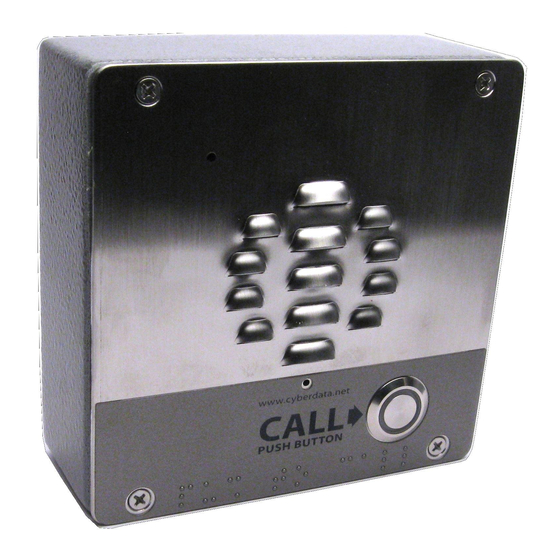
Page 14: Intercom Components
Intercom. Figure 2-1. Intercom Components Microphone Hole Speaker Drain Hole Call Button Section 2.3.8, "Call Button for and the Call Button LED" information about the functionality of the Call Button. Operations Guide 931544D CyberData Corporation... -
Page 15: Intercom Setup
12VDC power source as an alternative to Network PoE power. Use of these contacts for any other purpose will damage the device and void the product warranty. Terminal Block can accept 16 AWG wire Operations Guide 931544D CyberData Corporation... - Page 16 Wiring pins 7 and 8 of the terminal block to a switch will initiate a SIP call when the switch is closed. The call will go to the extension specified as the dial out extension on the SIP page. Figure 2-3. Remote Switch Connection Terminal Block Operations Guide 931544D CyberData Corporation...
-
Page 17: Using The On-Board Relay
This relay interface also has a general purpose input port that can be used to monitor an external switch and generate an event. For more information on the sensor options, see the Sensor Configuration Page on the web interface. Operations Guide 931544D CyberData Corporation... -
Page 18: Wiring The Circuit
Pin 4 - Relay Normally Open Contact Pin 5 - Sense Input Pin 6 - Sense Ground LED Strobe Light DC Source Sense Input 1 A @ 30 VDC Terminal Block of the CyberData Device Operations Guide 931544D CyberData Corporation... - Page 19 Section 2.4.13, "Configure the Door Strike Relay" for configuration options. *Caution Equipment Hazard: The door strike must have an internal or external mov or diode (for over voltage protection) when connecting directly to the module. GENERAL ALERT Operations Guide 931544D CyberData Corporation...
- Page 20 (for over voltage protection) when connecting directly to the module. GENERAL ALERT If you have questions about connecting door strikes or setting up the web configurable options, please contact our support department at the following website: http://support.cyberdata.net/ Operations Guide 931544D CyberData Corporation...
- Page 21 AC Source DC Source Door Lock Sense Input If you have questions about connecting door strikes or setting up the web configurable options, please contact our support department at the following website: http://support.cyberdata.net/ Operations Guide 931544D CyberData Corporation...
-
Page 22: Intercom Connectors
Installing the SIP Outdoor Intercom Intercom Setup 2.3.4 Intercom Connectors See the following figures and tables to identify the connectors and functions of the Intercom. Figure 2-8. Connector Locations—Board Top Operations Guide 931544D CyberData Corporation... - Page 23 ISP AT-Tiny Interface (Factory Only) Digital Microphone Interface (Not Used) Mute Disable Jumper—Jumper should be remvoed Enable AT-Tiny—Jumper should be installed Enable Write to EEPROM—Jumper should be installed JP10 Disables the intrusion sensor when installed. Operations Guide 931544D CyberData Corporation...
- Page 24 Installing the SIP Outdoor Intercom Intercom Setup Figure 2-9. Connector Locations—Board Bottom Operations Guide 931544D CyberData Corporation...
- Page 25 Terminal Block (see Figure 2-2) Reset jumper Auxiliary Strobe Connector Section 2.3.6, "RTFM Button" a.Do not install a jumper. Momentary short to reset. Permanent installation of a jumper would prevent the board from running all together. Operations Guide 931544D CyberData Corporation...
-
Page 26: Activity And Link Leds
The square, AMBER 100 Mb Link LED above the Ethernet port indicates that the • network 100 Mb connection has been established (see Figure 2-10). Figure 2-10. Activity and Link LED Link/Activity 100 Mb Link Operations Guide 931544D CyberData Corporation... -
Page 27: Rtfm Button
2-11) on the Intercom board to announce and confirm the Intercom’s IP Address and test to see if the audio is working. Note You must do these tests prior to final assembly. Figure 2-11. RTFM Button (SW1) RTFM button (SW1) Operations Guide 931544D CyberData Corporation... - Page 28 10.10.10.10 if a DHCP server is not present). Note Pressing and holding the RTFM button for longer than five seconds will restore the device to the factory default settings. Figure 2-12. RTFM Button (SW1) RTFM button (SW1) Operations Guide 931544D CyberData Corporation...
-
Page 29: Adjusting The Intercom Volume
Figure 2-13. RTFM Button (SW1) RTFM button (SW1) 2.3.7 Adjusting the Intercom Volume You can adjust the Intercom volume through the Volume, Multicast Volume, Ring Volume, and Sensor Volume settings on the Device Configuration Page. Operations Guide 931544D CyberData Corporation... -
Page 30: Call Button And The Call Button Led
Call Button LED will still blink during initialization and calls. • The Call Button LED flashes briefly at the beginning of RTFM mode. Figure 2-14. Call Button and Call Button LED Call Button and Call Button LED Operations Guide 931544D CyberData Corporation... -
Page 31: Configure The Intercom Parameters
Table 2-4. Factory Default Settings Parameter Factory Default Setting IP Addressing DHCP IP Address 10.10.10.10 Web Access Username admin Web Access Password admin Subnet Mask 255.0.0.0 Default Gateway 10.0.0.1 a. Default if there is not a DHCP server present. Operations Guide 931544D CyberData Corporation... -
Page 32: Intercom Web
Link to the Multicast page. Link to the Sensor page. Link to the Audiofiles page. Link to the Events page. Link to the Door Strike Relay page. Link to the Autoprovisioning page. Link to the Firmware page. Operations Guide 931544D CyberData Corporation... -
Page 33: Using The Toggle Help Button
2. You will see a question mark ( ) appear next to each web page item that has been provided with a short description by the Help feature. See Figure 2-16. Figure 2-16. Toggle Help Button and Question Marks Question mark appears next to the web page items Operations Guide 931544D CyberData Corporation... - Page 34 3. Move the mouse pointer to hover over the question mark ( ), and a short description of the web page item will appear. See Figure 2-17. Figure 2-17. Short Description Provided by the Help Feature A short description of the Question mark web page item will appear Operations Guide 931544D CyberData Corporation...
-
Page 35: Log In To The Configuration Home Page
Note You may also download CyberData’s VoIP Discovery Utility program which allows you to easily find and configure the default web address of the CyberData VoIP products. CyberData’s VoIP Discovery Utility program is available at the following website address: https://www.cyberdata.net/pages/discovery... - Page 36 Installing the SIP Outdoor Intercom Intercom Setup Figure 2-18. Home Page CyberData Outdoor Intercom 186200001 v20.0.1 v20.0.1 v20.0.1 Operations Guide 931544D CyberData Corporation...
- Page 37 Shows the current status of the Nightringer mode. Primary SIP Server Shows the current status of the Primary SIP Server. Backup Server 1 Shows the current status of Backup Server 1. Backup Server 2 Shows the current status of Backup Server 2. Operations Guide 931544D CyberData Corporation...
- Page 38 First click on the Toggle Help button, and you will see a question mark ( appear next to some of the web page items. Move the mouse pointer to hover over a question mark to see a short description of a specific web page item. Operations Guide 931544D CyberData Corporation...
-
Page 39: Configure The Device
Installing the SIP Outdoor Intercom Intercom Setup 2.4.5 Configure the Device 1. Click the Device menu button to open the Device page. See Figure 2-19. Figure 2-19. Device Configuration Page CyberData Outdoor Intercom Operations Guide 931544D CyberData Corporation... - Page 40 DTMF code used to pulse the relay when entered on a phone during a SIP call with the device. Relay will activate for Relay Pulse Duration seconds then deactivate. Activate Relay with DTMF Code must be enabled. Enter up to 25 digits (* and # are supported). Operations Guide 931544D CyberData Corporation...
- Page 41 Using Push to Talk prevents the operator from terminating a call by pressing the Call button. The call must be terminated by the phone user. Operations Guide 931544D CyberData Corporation...
- Page 42 First click on the Toggle Help button, and you will see a question mark ( ) appear next to some of the web page items. Move the mouse pointer to hover over a question mark to see a short description of a specific web page item. Operations Guide 931544D CyberData Corporation...
-
Page 43: Configure The Network Parameters
Installing the SIP Outdoor Intercom Intercom Setup 2.4.6 Configure the Network Parameters 1. Click the Network menu button to open the Network page (Figure 2-20). Figure 2-20. Network Configuration Page CyberData Outdoor Intercom Operations Guide 931544D CyberData Corporation... - Page 44 Specify the IEEE 802.1p VLAN priority level. Enter 1 digit. A value of 0 may cause the VLAN ID tag to be ignored. Click the Save button to save your configuration settings. Click on the Reboot button to reboot the system. Operations Guide 931544D CyberData Corporation...
- Page 45 ( ) appear next to some of the web page items. Move the mouse pointer to hover over a question mark to see a short description of a specific web page item. Operations Guide 931544D CyberData Corporation...
-
Page 46: Configure The Sip (Session Initiation Protocol) Parameters
Installing the SIP Outdoor Intercom Intercom Setup 2.4.7 Configure the SIP (Session Initiation Protocol) Parameters 1. Click on the SIP menu button to open the SIP page (Figure 2-21). Figure 2-21. SIP Configuration Page CyberData Outdoor Intercom Operations Guide 931544D CyberData Corporation... - Page 47 SIP server. Enter up to 64 alphanumeric characters. Backup SIP Auth ID Specify the Authenticate ID for the second backup SIP server. This parameter is required for SIP registration authentication. Enter up to 64 alphanumeric characters. Operations Guide 931544D CyberData Corporation...
- Page 48 SIP-URI for the device's Nightringer extension. Enter up to 64 alphanumeric characters. SIP Auth ID Specify the Authenticate ID for the SIP Server. This parameter is required for SIP registration authentication. Enter up to 64 alphanumeric characters. Operations Guide 931544D CyberData Corporation...
- Page 49 Move the mouse pointer to hover over a question mark to see a short description of a specific web page item. Note For specific server configurations, go to the following website address: https://www.cyberdata.net/pages/connecting-to-ip-pbx-servers Operations Guide 931544D CyberData Corporation...
- Page 50 DTMF tone '2', send out DTMF tone 5, wait 6 seconds, send out DTMF tone 4, wait 4 seconds, send out DTMF tone 1 Note The maximum number of total characters in the dial-out field is 64. Operations Guide 931544D CyberData Corporation...
- Page 51 Note Receiving point-to-point SiP calls may not work with all phones. Figure 2-22. SIP Page Set to Point-to-Point Mode CyberData Outdoor Intercom Device is set to NOT register with a SIP server 2.4.7.3 Delayed DTMF On the SIP Configuration page the dial out extension supports the addition of comma delimited pauses and sending additional DTMF tones (using rfc2833).
-
Page 52: Configure The Ssl Parameters
Installing the SIP Outdoor Intercom Intercom Setup 2.4.8 Configure the SSL Parameters 1. Click SSL menu button to open the SSL page (Figure 2-28). Figure 2-23. SSL Configuration Page CyberData Outdoor Intercom Operations Guide 931544D CyberData Corporation... - Page 53 Installing the SIP Outdoor Intercom Intercom Setup Figure 2-24. SSL Configuration Page Operations Guide 931544D CyberData Corporation...
- Page 54 Client Certificate When doing mutual authentication this device will present a client certificate with these parameters. Client CA Right click and Save Link As... to get the Cyberdata CA used to sign this client certificate. Test SSL Connection Server The ssl test server address as a fully qualified domain name or in IPv4 dotted decimal notation.
- Page 55 Installing the SIP Outdoor Intercom Intercom Setup 2.4.8.1 Certificate Info Window The Certificate Info Window provides details of the certificate. This window appears after clicking on the Info button. See Figure 2-25. Figure 2-25. Certificate Info Window Operations Guide 931544D CyberData Corporation...
- Page 56 The Remove Server Certificate Window will ask if the user wants to remove a certificate from the list of trusted certificates. This window appears after clicking on the Remove button. See Figure 2- Figure 2-26. Remove Server Certificate Window Operations Guide 931544D CyberData Corporation...
-
Page 57: Configure The Multicast Parameters
RTP audio streams. A paging zone can consist of one or many CyberData multicast group-enabled products. There is no limit to how many speakers can be in a given paging zone. Each multicast group is defined by a multicast address and port number. - Page 58 Installing the SIP Outdoor Intercom Intercom Setup Figure 2-27. Multicast Configuration Page CyberData Outdoor Intercom Operations Guide 931544D CyberData Corporation...
- Page 59 Group Numbers 1-25 are supported. Or, select Disabled to disable this channel. Click the Save button to save your configuration settings. Click on the Reboot button to reboot the system. Operations Guide 931544D CyberData Corporation...
- Page 60 SIP calls, multicast streams, ring tones, ringback tones, and nightring tones are all prioritized. Ringtones and Ringtones all play at the same priority level. This means that it is possible to have a nightring tone Nightringtones and a normal ringtone playing at the same time. Operations Guide 931544D CyberData Corporation...
-
Page 61: Configure The Sensor Configuration Parameters
Calling a preset extension can be set up as a point-to-point call, but currently can't send delayed DTMF tones. 1. Click Sensor menu button to open the Sensor page (Figure 2-28). Figure 2-28. Sensor Configuration Page CyberData Outdoor Intercom Operations Guide 931544D CyberData Corporation... - Page 62 Specify the extension the device will call when the intrusion sensor is activated. Enter up to 64 alphanumeric characters. Dial Out ID An additional Caller identification string added to outbound calls. Enter up to 64 alphanumeric characters. Operations Guide 931544D CyberData Corporation...
- Page 63 ( ) appear next to some of the web page items. Move the mouse pointer to hover over a question mark to see a short description of a specific web page item. Operations Guide 931544D CyberData Corporation...
-
Page 64: Configure The Audio Configuration Parameters
The Audiofiles page is used to add custom audio to the board. User uploaded audio will take precedence over the audio files shipped with the Intercom. 1. Click on the Audiofiles menu button to open the Audiofiles page (Figure 2-29). Figure 2-29. Audiofiles Configuration Page CyberData Outdoor Intercom Operations Guide 931544D CyberData Corporation... - Page 65 Installing the SIP Outdoor Intercom Intercom Setup Figure 2-30. Audiofiles Page Operations Guide 931544D CyberData Corporation...
- Page 66 '9' corresponds to the spoken word “nine.” Corresponds to the spoken word “dot.” (24 character limit) audiotest Corresponds to the message “This is the CyberData IP speaker test message...” (24 character limit) pagetone Corresponds to a simple tone used for beep on initialization and beep on page (24 character limit).
- Page 67 The Delete button will delete any user uploaded audio and restore the stock audio file. The Save button will download a new user audio file to the board once you've selected the file by using the Browse button. The Save button will delete any pre-existing user-uploaded audio files. Operations Guide 931544D CyberData Corporation...
- Page 68 RIFF (little-endian) data, WAVE audio, Microsoft PCM, 16 bit, mono 8000 Hz You can use the free utility Audacity to convert audio files into this format. See Figure 2-31 through Figure 2-33. Figure 2-31. Audacity 1 Figure 2-32. Audacity 2 Operations Guide 931544D CyberData Corporation...
- Page 69 Intercom Setup When you export an audio file with Audacity, save the output as: • WAV (Microsoft) signed 16 bit PCM. Figure 2-33. WAV (Microsoft) signed 16 bit PCM WAV (Microsoft) signed 16 bit PCM Operations Guide 931544D CyberData Corporation...
-
Page 70: Configure The Events Parameters
The Events page specifies a remote server that can be used to receive HTTP POST events when actions take place on the board. 1. Click on the Events menu button to open the Events page (Figure 2-34). Figure 2-34. Event Configuration Page CyberData Outdoor Intercom Operations Guide 931544D CyberData Corporation... - Page 71 Event Server Server IP Address The IPv4 address of the event server in dotted decimal notation. Server Port Specify the event server port number. The supported range is 0- 65536. Enter up to 5 digits. Operations Guide 931544D CyberData Corporation...
- Page 72 ( ) appear next to some of the web page items. Move the mouse pointer to hover over a question mark to see a short description of a specific web page item. Operations Guide 931544D CyberData Corporation...
- Page 73 Here are example packets for every event: POST xmlparse_engine HTTP/1.1 Host: 10.0.3.79 User-Agent: CyberData/1.0.0 Content-Length: 197 Content-Type: application/x-www-form-urlencoded <?xml version="1.0" encoding="ISO-8859-1"?> <cyberdata NAME='CyberData VoIP Device' MAC='0020f70015b6'> <event>POWERON</event> </cyberdata> POST xmlparse_engine HTTP/1.1 Host: 10.0.3.79 User-Agent: CyberData/1.0.0 Content-Length: 199 Content-Type: application/x-www-form-urlencoded <?xml version="1.0"...
- Page 74 Installing the SIP Outdoor Intercom Intercom Setup User-Agent: CyberData/1.0.0 Content-Length: 205 Content-Type: application/x-www-form-urlencoded <?xml version="1.0" encoding="ISO-8859-1"?> <cyberdata NAME='CyberData VoIP Device' MAC='0020f70015b6'> <event>CALL_TERMINATED</event> </cyberdata> POST xmlparse_engine HTTP/1.1 Host: 10.0.3.79 User-Agent: CyberData/1.0.0 Content-Length: 197 Content-Type: application/x-www-form-urlencoded <?xml version="1.0" encoding="ISO-8859-1"?> <cyberdata NAME='CyberData VoIP Device' MAC='0020f70015b6'>...
- Page 75 Installing the SIP Outdoor Intercom Intercom Setup User-Agent: CyberData/1.0.0 Content-Length: 234 Content-Type: application/x-www-form-urlencoded <?xml version="1.0" encoding="ISO-8859-1"?> <cyberdata NAME='CyberData VoIP Device' MAC='0020f70015b6'> <event>RELAY_DEACTIVATED</event> </cyberdata> POST xmlparse_engine HTTP/1.1 Host: 10.0.3.79 User-Agent: CyberData/1.0.0 Content-Length: 234 Content-Type: application/x-www-form-urlencoded <?xml version="1.0" encoding="ISO-8859-1"?> <cyberdata NAME='CyberData VoIP Device' MAC='0020f70015b6'>...
-
Page 76: Configure The Door Strike Relay
Windows application. This section describes operations for running firmware version 4.8 or later of the Dual Door Strike Relay. If you have an older version of the firmware, then please contact CyberData Technical Support. The version number appears in the... - Page 77 This button is only available when a relay is associated with a device. Note Associating a DSR does not require a reboot. However, you should reboot the device after disassociating a DSR. Operations Guide 931544D CyberData Corporation...
-
Page 78: Configure The Autoprovisioning Parameters
Note By default, the device will try to set up its configuration with autoprovisioning. 1. Click the Autoprov menu button to open the Autoprovisioning page. See Figure 2-36. Figure 2-36. Autoprovisioning Page CyberData Outdoor Intercom Operations Guide 931544D CyberData Corporation... - Page 79 Press the Download Template button to create an autoprovisioning file for the device. See Section 2.4.14.3, "Download Template Button" Autoprovisioning log The autoprovisioning log provides information about the latest autoprovisioning attempt (i.e. dhcp options and server accessed and files parsed or not found). Operations Guide 931544D CyberData Corporation...
- Page 80 Autoprovisioning files can contain the whole configuration or a subset of this file. The first autoprovisioning file can also contain links to other autoprovisioning files. The <MiscSettings> section contains some examples of additional autoprovisioning files: <MiscSettings> <DeviceName>CyberData VoIP Device</DeviceName> <!-- <AutoprovFile>common.xml</AutoprovFile>--> <!-- <AutoprovFile>sip_reg[macaddress].xml</AutoprovFile>-->...
- Page 81 When one of these options is set, the Files after Boot device will download its autoprovisioning files again, and if it finds any differences from the files it downloaded on boot, it will force a reboot and reconfigure. Operations Guide 931544D CyberData Corporation...
- Page 82 The autoprovisioning filename is set to “cyberdata/” On boot, the device will try to download: https://www.example.com/cyberdata/0020f7123456.xml ...and if this fails: https://www.example.com/cyberdata/000000cd.xml Audio files and firmware files will also add “cyberdata” to the URL before downloading. Operations Guide 931544D CyberData Corporation...
- Page 83 In this way, a generic autoprovisioning file can specify unique firmware for a range of products. The list of valid product strings: <ProductString>CallButton31</ProductString> <ProductString>EmergencyIntercom31</ProductString> <ProductString>EmergencyIntercom31SW</ProductString> <ProductString>IndoorIntercom31</ProductString> <ProductString>IndoorIntercom31SW</ProductString> <ProductString>IndoorKeypad31</ProductString> <ProductString>IndoorKeypad31SW</ProductString> <ProductString>OfficeRinger31</ProductString> <ProductString>OfficeRinger31SW</ProductString> <ProductString>OutdoorIntercom31</ProductString> <ProductString>OutdoorIntercom31SW</ProductString> <ProductString>OutdoorKeypad31</ProductString> <ProductString>OutdoorKeypad31SW</ProductString> <ProductString>Strobe31</ProductString> <ProductString>Strobe31SW</ProductString> Operations Guide 931544D CyberData Corporation...
- Page 84 000000cd.xml. This file exists, and Device1 parses the three elements. 1. Device1 changes its device name to CyberData Autoprovisioned. 2. Device1 finds an AutoprovFile element containing the filename sip_common.xml. The device downloads sip_common.xml from “https://autoprovtest.server.net,”...
- Page 85 TFTP server at 10.0.1.3. and imports these settings. The device name is set to CyberData Autoprovisioned, the SIP server is set to 10.0.0.253, and the port is set to 5060. Device2 does the same except it downloads 0020f7020002.xml on boot and imports these values instead.
- Page 86 You can force a change to the audio files on the board by clicking Restore Default on the Audio page or by changing the autoprovisioning file with “default” set as the file name. Operations Guide 931544D CyberData Corporation...
- Page 87 "http://test.cyberdata.net"; # OPTION 66 option option-150 10.0.0.252; # OPTION 150 # These two lines are needed for option 43 vendor-option-space VendorInfo; # OPTION 43 option VendorInfo.text "http://test.cyberdata.net"; # OPTION 43 range 10.10.0.1 10.10.2.1; } Operations Guide 931544D CyberData Corporation...
- Page 88 4. At this point, you can open and edit the autoprovisioning template to change the configuration settings in the template for the unit. 5. You can then upload the autoprovisioning file to a TFTP or HTTP server where the file can be loaded onto other devices. Operations Guide 931544D CyberData Corporation...
-
Page 89: Upgrade The Firmware
Intercom Setup 2.5 Upgrade the Firmware Note CyberData strongly recommends that you do not upgrade the firmware when the device is likely to be in use. To upgrade the firmware of your device: 1. Download the latest firmware file from the Downloads tab at the following webpage: https://www.cyberdata.net/products/011186... - Page 90 Intercom Setup 6. Select the firmware file. This reveals the Upload button (Figure 2-39). Figure 2-39. Upload Button CyberData Outdoor Intercom Upload button Status Messages Upload Post Processing bar Upload Progress bar 7. Click on the Upload button. After selecting the Upload button, you will see the progress of the upload in the Upload Progress bar.
- Page 91 Note: This button only appears after the user has selected a firmware file. Upload progress Status bar indicates the progress in uploading the file. Upload Post Processing Status bar indicates the progress of the software installation. Status Messages Messages relevant to the firmware update process appear here. Operations Guide 931544D CyberData Corporation...
-
Page 92: Reboot The Device
Section 2.4.4, "Log in to the Configuration Home Page". 2. Click on the Reboot button on the Home page (Figure 2-40). A normal restart will occur. Figure 2-40. Home Page CyberData Outdoor Intercom 186200001 v20.0.1 v20.0.1 v20.0.1 Reboot Operations Guide... -
Page 93: Command Interface
--user admin --password admin --auth-no-challenge --no- check-certificate "https://10.10.1.138/audiofiles/" --quiet -O /dev/ null --post-data "3=Play" Play the "4" audio file wget --user admin --password admin --auth-no-challenge --no- check-certificate "https://10.10.1.138/audiofiles/" --quiet -O /dev/ null --post-data "4=Play" Operations Guide 931544D CyberData Corporation... - Page 94 --user admin --password admin --auth-no-challenge --no- check-certificate "https://10.10.1.138/audiofiles/" --quiet -O /dev/ null --post-data "doorajar=Play" Play the "Night Ring" audio file wget --user admin --password admin --auth-no-challenge --no- check-certificate "https://10.10.1.138/audiofiles/" --quiet -O /dev/ null --post-data "nightring=Play" Operations Guide 931544D CyberData Corporation...
- Page 95 Device Action HTTP Post Command Swap boot partitions wget --user admin --password admin --auth-no-challenge --quiet - O /dev/null --no-check-certificate "https://10.10.1.154/command" -- post-data "request=swap_boot_partition" a.Type and enter all of each http POST command on one line. Operations Guide 931544D CyberData Corporation...
-
Page 96: Appendix A Mounting The Intercom
Table A-2. Optional Accessories (for gooseneck mounting) Quantity Part Name Illustration Carriage bolt nuts Carriage bolts Carriage bolt washers Table A-3. Optional Accessories Quantity Part Name Illustration Spacer for half-inch set conduit connector 531085* hole plug assembly Operations Guide 931544D CyberData Corporation... -
Page 97: Dimensions
DIMENSIONS ARE IN INCHES [MILLIMETER] Figure A-2. Unit Dimensions—Rear View with Mounting Hole Locations Dimensions are in Inches [Millimeter] 0.869 [22.07] ø0.280 [ø7.11] (4 Places) ø0.854 [ø21.69] 3.380 [85.85] 1.690 [42.93] 1.690 0.869 [22.07] [42.93] 3.380 [85.85] Operations Guide 931544D CyberData Corporation... - Page 98 Mounting the Intercom Dimensions Figure A-3. Shroud Dimensions—Front and Side View with Mounting Hole Locations 3.434 [87.23] 5.276 [134.00] ø0.280 [ø7.11] (4 PLACES) ø0.854 [ø21.69] 1.690 [42.93] 3.380 [85.85] 0.948 [24.07] Dimensions are in Inches [Millimeter] Operations Guide 931544D CyberData Corporation...
-
Page 99: Overview Of Installation Types
An overview of the installation types and the required components are provided in Table A-4. Table A-4. Overview of Installation Types Installation Type What You Need Outdoor, on surface 011186 Intercom only Outdoor, on surface with shroud (increased resistance) 011186 Intercom 011188 Weather Shroud (sold separately) Operations Guide 931544D CyberData Corporation... -
Page 100: Network Cable Entry Restrictions
Figure A-4 for the conduit mounting restrictions (side entry). Figure A-4. Conduit Mounting Restrictions (Side Entry) Hole Plug Assembly 5/32" Spacer 1/2" Set Screw Connector (Not Provided) 1/2" Conduit (Not Provided) Network Cable (Not Provided) Operations Guide 931544D CyberData Corporation... -
Page 101: Conduit Mounting Restrictions (Rear Entry Without Shroud)
Figure A-6 for the conduit mounting restrictions (rear entry with shroud). Figure A-6. Conduit Mounting Restrictions (Rear Entry with Shroud) Spacer 1/2" Conduit Here Connector (Not Provided) 1/2" Conduit (Not Provided) Network Cable (Not Provided) Operations Guide 931544D CyberData Corporation... -
Page 102: Ground Cable Installation
SIP Outdoor Intercom. Figure A-7. Ground Cable Installation Ground Wire Ground Lug (Not Provided) Note: To mount the intercom, use methods compliant with local electrical codes. Operations Guide 931544D CyberData Corporation... -
Page 103: Service Loop Cable Routing
Figure A-8. Ground Cable Service Loop Routing Route cable(s) inside of the Route Cable(s) inside Gang Box to Gang Box to create the service loop. Creates Service Loop Ground Wire (not provided) Ground Wire (Not Provided) Ground Lug Ground Lug Operations Guide 931544D CyberData Corporation... - Page 104 Figure A-9. Network Cable Service Loop Routing Route cable(s) inside of the Route Cable(s) inside Gang Box to Gang Box to create the service loop. Creates Service Loop Network Cable (not provided) Network Cable (Not Provided) Operations Guide 931544D CyberData Corporation...
-
Page 105: Securing The Intercom
PCB assembly to the gang box. To prevent over-torque damage to the gasket, do not apply more than 10 inch-pounds force. Over-torquing will cause GENERAL ALERT the gasket to tear, risk moisture intrusion, and effectively void the manufacturer's warranty. Operations Guide 931544D CyberData Corporation... -
Page 106: Additional Mounting Options
(Sold Separate) 1/4" Washer (3x) 1/4" Nut (3x) 2-Gang Box Ground Cable (Not Provided) Rotate 2-Gang Box Ground Lug for Desire Conduit Mounting Direction 1/2" Set Screw Connector Nut Security Torx Screws Faceplate & PCB Assembly Operations Guide 931544D CyberData Corporation... -
Page 107: Concrete Wall Mounting Option (Not Provided)
SEALANT TO (Hole Plug, EXPOSED JOINTS Washer & Nut) 1/4" Concrete Wall Anchors (Not Provided) Spacer (One Provided) 1/2” Set Screw Connector 1/4" Carriage Screw (Not Provided) (Not Provided) 1/2" Conduit (Not Provided) Network Cable In Operations Guide 931544D CyberData Corporation... -
Page 108: Goose Neck Mounting Option (Not Provided)
(SOLD SEPARATELY) Security Torx Hole Plug Assembly [Hole Plug] (REMOVE HOLE PLUG ASSEMBLY FROM 2-GANG BOX BEFORE FASTEN IT TO SHROUD AND/OR GOOSENECK) 1/4" Washer (3x) 1/4" Nut (3x) Faceplate NETWORK Assembly CABLE (NOT PROVIDED) Operations Guide 931544D CyberData Corporation... -
Page 109: Ground Cable Installation For Goose Neck Mounting Option
EXPOSED JOINTS to Network Connector GOOSENECK (NOT PROVIDED) Ground Lug GOOSENECK [CUTAWAY VIEW TO SHOW Ground Cable CABLES ROUTING] (NOT PROVIDED) (to Ground Lug) Grounding Rod and Clamp (NOT PROVIDED) NETWORK & GROUND CABLES IN Operations Guide 931544D CyberData Corporation... -
Page 110: Appendix B Setting Up A Tftp Server
1. Install and start the software. 2. Select File Configure Security tab Transmit Only. 3. Make a note of the default directory name, and then move the firmware files to be uploaded to that directory. Operations Guide 931544D CyberData Corporation... -
Page 111: Appendix C Troubleshooting/Technical Support
To see a list of frequently asked questions for your product, click on the FAQs tab at the following webpage: https://www.cyberdata.net/products/011186 C.2 Documentation The documentation for this product is released in an English language version only. To download PDF copies of CyberData product documentation, click on the Downloads tab at the following webpage: https://www.cyberdata.net/products/011186 Operations Guide 931544D... -
Page 112: Contact Information
Support form at the following website: http://support.cyberdata.net/ The Support Form initiates a ticket which CyberData uses for tracking customer requests. Most importantly, the Support Form tells us which PBX system and software version that you are using, the make and model of the switch, and other important information. This information is essential for troubleshooting. -
Page 113: Index
33, 37 activate relay (door sensor) 55 contact information 105 activate relay (intrusion sensor) 55 contact information for CyberData 105 activity LED 19 current network settings 37 address, configuration login 28 CyberData contact information 105 alternative power input 4 announcing a device’s IP address 21... - Page 114 3 securing the intercom 98 service loop cable routing 96 side conduit network cable entry restrictions 93 mounting components 89 multicast configuration 57 Multicast IP Address 52 identifying your product 1 import settings 31 Operations Guide 931544D CyberData Corporation...
- Page 115 SIP servers supported 3 product specifications 4 unregister from 41 protocol 4 user ID for login 40 protocols supported 3 SIP server configuration 40 push to talk, DTMF 35 SIP volume 33 speaker output 4 Operations Guide 931544D CyberData Corporation...
- Page 116 33 push to talk volume 33 ring volume 33 sensor volume 33 SIP volume 33 warranty policy at CyberData 105 web access password 24 web access username 24 web configuration log in address 28 web page navigation 25...
Need help?
Do you have a question about the 011186 and is the answer not in the manual?
Questions and answers