CyberData 11186 Operation Manual
Voip v3 outdoor intercom
Hide thumbs
Also See for 11186:
- Operation manual (123 pages) ,
- Installation quick reference (4 pages) ,
- Quick start manual (4 pages)
Table of Contents
Advertisement
Quick Links
Download this manual
See also:
Operating Manual
Advertisement
Table of Contents

Related Manuals for CyberData 11186


Summary of Contents for CyberData 11186
- Page 1 The IP Endpoint Company VoIP V3 Outdoor Intercom Operations Guide Part #011186 Document Part #930472C for Firmware Version 7.1.6 CyberData Corporation 3 Justin Court Monterey, CA 93940 (831) 373-2601...
- Page 2 CyberData Corporation. This manual, and the products, software, firmware, and/or hardware described in this manual are the property of CyberData Corporation, provided under the terms of an agreement between CyberData Corporation and recipient of this manual, and their use is subject to that agreement and its terms.
- Page 3 Section 2.3.2, "Connecting the Intercom to the Auxiliary Relay". • Updates Figure 2-3, "Auxiliary Relay Wiring Diagram". • Updates Appendix A, “Mounting the Intercom”. • Adds Figure A-2, "Unit Dimensions—Rear View with Mounting Hole Locations". Operations Guide 930472C CyberData Corporation...
-
Page 4: Important Safety Instructions
Electrical Hazard: This product should be installed by a licensed electrician according to all local electrical and building codes. GENERAL ALERT Warning Electrical Hazard: To prevent injury, this apparatus must be securely attached to the floor/wall in accordance with the installation instructions. GENERAL ALERT CyberData Corporation 930472C Operations Guide... - Page 5 Potential safety hazards are identified in this manual through the use of words Danger, Warning, and Caution, the specific hazard type, and pictorial alert icons. CyberData Corporation 930472C Operations Guide...
-
Page 6: Table Of Contents
A.8.3 Goose Neck Mounting Option (Not Provided) ..............77 A.8.4 Ground Cable Installation for Goose Neck Mounting Option ........78 Appendix B Setting up a TFTP Server B.1 Set up a TFTP Server ......................79 B.1.1 In a LINUX Environment ....................79 Operations Guide 930472C CyberData Corporation... - Page 7 C.4.1 Warranty & RMA Returns within the United States ............82 C.4.2 Warranty & RMA Returns Outside of the United States ..........82 C.4.3 Spare in the Air Policy ....................82 C.4.4 Return and Restocking Policy ..................83 C.4.5 Warranty and RMA Returns Page ................83 Operations Guide 930242G CyberData Corporation...
-
Page 8: Chapter 1 Product Overview
1.1 How to Identify This Product To identify the VoIP V3 Outdoor Intercom, look for a model number label similar to the one shown in Figure 1-1. The model number on the label should be 011186. Figure 1-1. Model Number Label WWW.CYBERDATA.NET... -
Page 9: Typical System Installation
802.3af Compliant Ethernet Switch V3 Intercom V3 Intercom V3 Intercom IP Phone IP PBX Server Figure 1-3. Typical Installation—Mass Notification Generic PoE Switch Strobe Speaker Loudspeaker V3 Intercom IP Phone IP PBX Server Light Amplifier Operations Guide 930472C CyberData Corporation... - Page 10 Electrical Hazard: This product should be installed by a licensed electrician according to all local electrical and building codes. GENERAL ALERT Warning Electrical Hazard: To prevent injury, this apparatus must be securely attached to the floor/wall in accordance with the installation instructions. GENERAL ALERT Operations Guide 930472C CyberData Corporation...
-
Page 11: Product Features
The VoIP V3 Intercom has the following features: • Supports SRST (Survivable Remote Site Telephony) in a Cisco environment. SRST parameters are entered statically into the CyberData product's internal webpage. • • Dual speeds of 10 Mbps and 100 Mbps •... -
Page 12: Supported Protocols
Packet Time 20 ms 1.5 Supported SIP Servers Go to the following link to find the VoIP V3 Outdoor Intercom product page which will have information on how to configure the device for various supported SIP servers: http://www.cyberdata.net/support/server/index.html Operations Guide 930472C CyberData Corporation... -
Page 13: Product Specifications
10/100 Mbps Power Requirement PoE 802.3af compliant or +12 to 24 VDC at 1000 mA (500 mA minimum) Protocol Part Number 011186 Dimensions 5.118” x 5.118” x 2.25” Weight 1.6 lbs./shipping weight of 2.2 lbs. (0.7 kg/shipping weight of 1.0kg) -
Page 14: Dimensions
Figure 1-5. Unit Dimensions—Front and Side View Figure 1-6. Unit Dimensions—Rear View and Mounting Hole Locations Dimensions are in Inches [Millimeter] 0.869 [22.07] ø0.280 [ø7.11] (4 Places) ø0.854 [ø21.69] 3.380 [85.85] 1.690 [42.93] 1.690 0.869 [22.07] [42.93] 3.380 [85.85] Operations Guide 930472C CyberData Corporation... - Page 15 Sensor Intrusion Sensor from 3 mm (Minimum) to 14 mm (Maximum) 0.118 [3.0] 0.551 [14.0] 0.156" [4.0] THROUGH HOLE 82 DEGREES COUNTERSUNK (4 PLACES) 4.000 [101.60] 1.986 [50.45] 5.118 [130.00] DIMENSIONS ARE IN INCHES [MILLIMETER] Operations Guide 930472C CyberData Corporation...
- Page 16 Figure 1-9. PCB Dimensions and Intrusion Sensor Range 1.169 [29.70] Effective Range for Intrusion Sensor to Function from 3 mm to 14 mm ø0.138 [ø3.51] 0.551 [14.00] Fits #6-32 Machine Screw 0.118 [3.00] 0.063 [1.60] (4 Places) BOTTOM SIDE TOP SIDE JP1 JP5 <...
-
Page 17: Chapter 2 Installing The Voip V3 Intercom
2 Installing the VoIP V3 Outdoor Intercom 2.1 Parts List Table 2-1 illustrates the VoIP V3 Intercom parts. Table 2-1. Parts List Quantity Part Name Illustration Intercom Assembly Installation Quick Reference Guide Intercom Mounting Accessory Kit Operations Guide 930472C CyberData Corporation... -
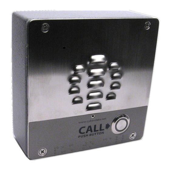
Page 18: Intercom Components
Intercom . Figure 2-1. Intercom Components Microphone Hole Speaker Drain Hole Call Button Section 2.3.7, "Call Button and the Call Button LED" information about the functionality of the Call Button. Operations Guide 930472C CyberData Corporation... -
Page 19: Intercom Setup
Contacts 1 & 2 are ONLY for powering the Intercom from a non-PoE +12VDC power source as an alternative to Network PoE power. Use of these contacts for any other purpose will damage the Intercom and void the product warranty. Operations Guide 930472C CyberData Corporation... -
Page 20: Connecting The Intercom To The Auxiliary Relay
DTMF tones generated from the phone being called. The DTMF tones are selectable from the web interface as well. Note The three digit code for the auxiliary relay must be sent in conformance with RFC2833 DTMF generation. Operations Guide 930472C CyberData Corporation... - Page 21 Figure 2-3. Auxiliary Relay Wiring Diagram Example of External Relay (not supplied) High PIV UltraFast Solid State Controlled Device Switching Diode Such As Mechanical Electric Door Strike Relay Strobe Light Output Contacts AC or DC rated Intercom PCB Depending Upon Controlled Device Requirements AC or DC...
-
Page 22: Intercom Connectors
See the following figures and tables to identify the connectors and functions of the Intercom. Figure 2-4. Connector Locations Table 2-2. Connector Functions Connector Function Call Button. LED Interface Microphone Interface Speaker Interface Proximity Sensor Interface - N/A Operations Guide 930472C CyberData Corporation... - Page 23 Table 2-3. Connector Functions Connector Function PoE Network Connection (RJ-45 ethernet) Terminal Block (see Figure 2-2) Factory Only—Console Port Factory Only—JTAG Factory Only—Reset Factory Only—Watch Dog Factory Only—Boot Mode JP10 Disables the intrusion sensor when installed. Operations Guide 930472C CyberData Corporation...
-
Page 24: Activity And Link Leds
Link light changes color to confirm the auto-negotiated data speed rate: • The Link light is YELLOW at 10 Mbps. • The Link light is ORANGE at 100 Mbps. Figure 2-6. Activity and Link LED Link Activity Operations Guide 930472C CyberData Corporation... -
Page 25: Rtfm Button
10.10.10.10 if a DHCP server is not present). Note Pressing and holding the RTFM button for longer than five seconds will restore the device to the factory default settings. Figure 2-8. RTFM Button (SW1) Operations Guide 930472C CyberData Corporation... -
Page 26: Adjusting The Intercom Volume
The device will use DHCP to obtain the new IP address (DHCP-assigned address or default to 10.10.10.10 if a DHCP server is not present). Figure 2-9. RTFM Button 2.3.6 Adjusting the Intercom Volume You can adjust the Intercom volume through the Speaker Volume setting on the Device Configuration Page. Operations Guide 930472C CyberData Corporation... -
Page 27: Call Button And The Call Button Led
Call Button LED will still blink during initialization and calls. • The Call Button LED flashes briefly at the beginning of RTFM mode. Figure 2-10. Call Button and Call Button LED Call Button and Call Button LED Operations Guide 930472C CyberData Corporation... -
Page 28: Configure The Intercom Parameters
Table 2-4. Factory Default Settings Parameter Factory Default Setting IP Addressing DHCP IP Address 10.10.10.10 Web Access Username admin Web Access Password admin Subnet Mask 255.0.0.0 Default Gateway 10.0.0.1 a. Default if there is not a DHCP server present. Operations Guide 930472C CyberData Corporation... -
Page 29: Intercom Web
Link to the Sensor Configuration page. Link to the Multicast Configuration page. Link to the Audio Configuration page. Link to the Event Configuration page. Link to the Autoprovisioning Configuration page. Link to the Update Firmware page. Operations Guide 930472C CyberData Corporation... -
Page 30: Log In To The Configuration Home Page
Make sure that the PC is on the same IP network as the Intercom. Note You may also download CyberData’s VoIP Discovery Utility program which allows you to easily find and configure the default web address of the CyberData VoIP products. - Page 31 2. When prompted, use the following default Web Access Username and Web Access Password to access the Home Page (Figure 2-11): Web Access Username: admin Web Access Password: admin Figure 2-11. Home Page Operations Guide 930472C CyberData Corporation...
- Page 32 Shows the current status of Backup Server 2. Click the Save button to save your configuration settings. Note: You need to reboot for changes to take effect. Click on the Reboot button to reboot the system. Operations Guide 930472C CyberData Corporation...
-
Page 33: Configure The Device
2.4.4 Configure the Device 1. Click the Device Configuration button to open the Device Configuration page. See Figure 2- Figure 2-12. Device Configuration Page Operations Guide 930472C CyberData Corporation... - Page 34 Intercom speaker until someone presses the button. Button Lit When Idle When selected, the Call Button remains lit when idle. Play Ringback Tone When selected, you will hear a ringback tone while making a call. Operations Guide 930472C CyberData Corporation...
- Page 35 3. The device will play back the recorded audio. Click on the Test Relay button to do a relay test. Click on the Reboot button to reboot the system. 3. After changing the parameters, click the Save button. Operations Guide 930472C CyberData Corporation...
-
Page 36: Configure The Network Parameters
2.4.5 Configure the Network Parameters 1. Click the Networking button to open the Network Configuration page (Figure 2-13). Figure 2-13. Network Configuration Page Operations Guide 930472C CyberData Corporation... - Page 37 Intercom if appropriate. 4. Connect the Intercom to the target network. 5. From a system on the same network as the Intercom, open a browser with the new IP address of the Intercom. Operations Guide 930472C CyberData Corporation...
-
Page 38: Configure The Sip Parameters
2.4.6 Configure the SIP Parameters 1. Click SIP Config to open the SIP Configuration page (Figure 2-14). Note For specific server configurations, go to the following website address: http://www.cyberdata.net/support/server/index.html Figure 2-14. SIP Configuration Page Operations Guide 930472C CyberData Corporation... - Page 39 Type the Outbound Proxy Port number (8 character limit). Register with a SIP Server Check this box to enable SIP Registration. For information about Point-to-Point Configuration, see Section 2.4.6.2, "Point-to-Point Configuration". Re-registration Interval (in seconds) Type the SIP Registration lease time (in seconds) Operations Guide 930472C CyberData Corporation...
- Page 40 DTMF tone '2', send out DTMF tone 5, wait 6 seconds, send out DTMF tone 4, wait 4 seconds, send out DTMF tone 1 Note The maximum number of total characters in the dial-out field is 64. Operations Guide 930472C CyberData Corporation...
- Page 41 Point-to-Point calls. The delayed DTMF functionality is available in the Point-to-Point Mode. Note Receiving point-to-point SiP calls may not work with all phones. Figure 2-15. SIP Configuration Page Set to Point-to-Point Mode Intercom is set to NOT register with a SiP server Operations Guide 930472C CyberData Corporation...
- Page 42 DTMF tone '2', send out DTMF tone 5, wait 6 seconds, send out DTMF tone 4, wait 4 seconds, send out DTMF tone 1 Note The maximum number of total characters in the dial-out field is 25. Operations Guide 930472C CyberData Corporation...
-
Page 43: Configure The Nightringer Parameters
Nightringer requires SIP Registration. Nightringer cannot be used in peer to peer mode. GENERAL ALERT 1. Click on the Nightringer button to open the Nightringer Configuration page. See Figure 2-16. Figure 2-16. Nightringer Configuration Setup Operations Guide 930472C CyberData Corporation... - Page 44 Click the Save button to save your configuration settings. Note: You need to reboot for changes to take effect. Click on the Reboot button to reboot the system. 3. After changing the parameters, click on the Save button. Operations Guide 930472C CyberData Corporation...
-
Page 45: Configure The Sensor Configuration Parameters
Loop an audio file out of the Intercom speaker until the sensor is deactivated • Call a preset extension and play a pre-recorded audio file (once) Note Calling a preset extension can be set up as a point-to-point call, but currently can't send delayed DTMF tones. Operations Guide 930472C CyberData Corporation... - Page 46 1. Click Sensor Config to open the Sensor Configuration page (Figure 2-17). Figure 2-17. Sensor Configuration Page Operations Guide 930472C CyberData Corporation...
- Page 47 Click the Save button to save your configuration settings. Note: You need to reboot for changes to take effect. Click on the Reboot button to reboot the system. 3. After changing the parameters, click Save Settings. Operations Guide 930472C CyberData Corporation...
-
Page 48: Configure The Multicast Parameters
The Multicast Configuration page allows the Intercom to join up to 10 paging zones for receiving ulaw/alaw encoded RTP audio streams. A paging zone can consist of one or many CyberData multicast group-enabled products. There is no limit to how many devices can be in a given paging zone. - Page 49 SIP calls, multicast streams, ring tones, ringback tones, and nightring tones are all prioritized. Ringtones and Ringtones all play at the same priority level. This means that it is possible to have a nightring tone Nightringtones and a normal ringtone playing at the same time. Operations Guide 930472C CyberData Corporation...
-
Page 50: Configure The Audio Configuration Parameters
The Audio Configuration page is used to add custom audio to the board. User uploaded audio will take precedence over the audio files shipped with the Intercom. 1. Click Audio Config to open the Audio Configuration page (Figure 2-19). Figure 2-19. Audio Configuration Page Operations Guide 930472C CyberData Corporation... - Page 51 Figure 2-20. Audio Configuration Page (continued) Operations Guide 930472C CyberData Corporation...
- Page 52 '9' corresponds to the spoken word “nine.” Corresponds to the spoken word “dot.” (24 character limit) Audiotest Corresponds to the message “This is the CyberData IP speaker test message...” (24 character limit) Page tone Corresponds to a simple tone used for beep on initialization and beep on page (24 character limit).
- Page 53 RIFF (little-endian) data, WAVE audio, Microsoft PCM, 16 bit, mono 8000 Hz You can use the free utility Audacity to convert audio files into this format. See Figure 2-21 through Figure 2-23. Figure 2-21. Audacity 1 Figure 2-22. Audacity 2 Operations Guide 930472C CyberData Corporation...
- Page 54 When you export an audio file with Audacity, save the output as: • WAV (Microsoft) signed 16 bit PCM. Figure 2-23. WAV (Microsoft) signed 16 bit PCM WAV (Microsoft) signed 16 bit PCM Operations Guide 930472C CyberData Corporation...
-
Page 55: Configure The Event Parameters
Click the Event Config button to open the Event Configuration page (Figure 2-24). The Event Configuration page specifies a remote server that can be used to receive HTTP POST events when actions take place on the board. Figure 2-24. Event Configuration Page Operations Guide 930472C CyberData Corporation... - Page 56 Click the Save button to save your configuration settings. Note: You need to reboot for changes to take effect. Click on the Test Event button to test an event. Click on the Reboot button to reboot the system. Operations Guide 930472C CyberData Corporation...
- Page 57 Here are example packets for every event: POST xmlparse_engine HTTP/1.1 Host: 10.0.3.79 User-Agent: CyberData/1.0.0 Content-Length: 197 Content-Type: application/x-www-form-urlencoded <?xml version="1.0" encoding="ISO-8859-1"?> <cyberdata NAME='CyberData VoIP Device' MAC='0020f70015b6'> <event>POWERON</event> </cyberdata> POST xmlparse_engine HTTP/1.1 Host: 10.0.3.79 User-Agent: CyberData/1.0.0 Content-Length: 199 Content-Type: application/x-www-form-urlencoded <?xml version="1.0"...
- Page 58 User-Agent: CyberData/1.0.0 Content-Length: 205 Content-Type: application/x-www-form-urlencoded <?xml version="1.0" encoding="ISO-8859-1"?> <cyberdata NAME='CyberData VoIP Device' MAC='0020f70015b6'> <event>CALL_TERMINATED</event> </cyberdata> POST xmlparse_engine HTTP/1.1 Host: 10.0.3.79 User-Agent: CyberData/1.0.0 Content-Length: 197 Content-Type: application/x-www-form-urlencoded <?xml version="1.0" encoding="ISO-8859-1"?> <cyberdata NAME='CyberData VoIP Device' MAC='0020f70015b6'> <event>RINGING</event> </cyberdata> POST xmlparse_engine HTTP/1.1 Host: 10.0.3.79...
- Page 59 User-Agent: CyberData/1.0.0 Content-Length: 234 Content-Type: application/x-www-form-urlencoded <?xml version="1.0" encoding="ISO-8859-1"?> <cyberdata NAME='CyberData VoIP Device' MAC='0020f70015b6'> <event>RELAY_DEACTIVATED</event> </cyberdata> POST xmlparse_engine HTTP/1.1 Host: 10.0.3.79 User-Agent: CyberData/1.0.0 Content-Length: 234 Content-Type: application/x-www-form-urlencoded <?xml version="1.0" encoding="ISO-8859-1"?> <cyberdata NAME='CyberData VoIP Device' MAC='0020f70015b6'> <event>NIGHTRINGING</event> </cyberdata> Operations Guide 930472C...
-
Page 60: Configure The Autoprovisioning Parameters
2.4.12 Configure the Autoprovisioning Parameters 1. Click the Autoprovisioning button to open the Autoprovisioning Configuration page. Figure 2-25. Figure 2-25. Autoprovisioning Configuration Page Operations Guide 930472C CyberData Corporation... - Page 61 Click the Save button to save your configuration settings. Note: You need to reboot for changes to take effect. Click on the Reboot button to reboot the system. 3. After changing the parameters, click the Save button. Operations Guide 930472C CyberData Corporation...
- Page 62 The board gets its autoprovisioning information from an XML-formatted file hosted from a TFTP server. CyberData will provide a template for this XML file and the user can modify it for their own use.
- Page 63 3. The board downloads and writes the firmware file again. CyberData has timed a firmware upgrade at 140 seconds. Therefore, if you suspect the board is stuck in a loop, either remove or comment out the FirmwareVersion line in the XML file and let the board boot as it normally does.
- Page 64 Delete button on the Audio Configuration page which will restore the default audio file. You can also change the autoprovisioning file with the word default set as the file name. Operations Guide 930472C CyberData Corporation...
-
Page 65: Upgrade The Firmware And Reboot The Intercom
3. Log in to the Intercom home page as instructed in Section 2.4.3, "Log in to the Configuration Home Page". 4. Click the Update Firmware button to open the Upgrade Firmware page. See Figure 2-26. Operations Guide 930472C CyberData Corporation... - Page 66 Shows the current firmware version. Use the Browse button to navigate to the location of the Intercom firmware file that you want to upload. Click on the Submit button to automatically upload the selected firmware and reboot the system. Operations Guide 930472C CyberData Corporation...
-
Page 67: Reboot The Intercom
To reboot a Intercom, log in to the web page as instructed in Section 2.4.3, "Log in to the Configuration Home Page". 1. Click Reboot (Figure 2-27). A normal restart will occur. Figure 2-27. Reboot System Section Reboot Operations Guide 930472C CyberData Corporation... -
Page 68: Command Interface
Play the "2" audio file wget --user admin --password admin --auth-no-challenge --quiet - O /dev/null "http://10.0.3.71/cgi-bin/audioconfig.cgi" --post-data "play_2=yes" Play the "3" audio file wget --user admin --password admin --auth-no-challenge --quiet - O /dev/null "http://10.0.3.71/cgi-bin/audioconfig.cgi" --post-data "play_3=yes" Operations Guide 930472C CyberData Corporation... - Page 69 Play the "Intrusion Sensor Triggered" audio file wget --user admin --password admin --auth-no-challenge --quiet - O /dev/null "http://10.0.3.71/cgi-bin/audioconfig.cgi" --post-data "play_intrusionsensortriggered=yes" Play the "Door Ajar" audio file wget --user admin --password admin --auth-no-challenge --quiet - O /dev/null "http://10.0.3.71/cgi-bin/audioconfig.cgi" --post-data "play_doorajar=yes" Operations Guide 930472C CyberData Corporation...
- Page 70 Delete the "Rebooting" audio file wget --user admin --password admin --auth-no-challenge --quiet - O /dev/null "http://10.0.3.71/cgi-bin/audioconfig.cgi" --post-data "delete_rebooting=yes" Delete the "Restoring Default" audio file wget --user admin --password admin --auth-no-challenge --quiet - O /dev/null "http://10.0.3.71/cgi-bin/audioconfig.cgi" --post-data "delete_restoringdefault=yes" Operations Guide 930472C CyberData Corporation...
- Page 71 --user admin --password admin --auth-no-challenge --quiet - O /dev/null "http://10.0.3.71/cgi-bin/sensorconfig.cgi" --post-data "intrusiontest=yes" a.Type and enter all of each http POST command on one line. b. Must be in point-to-point mode see Section 2.4.6.2, "Point-to-Point Configuration" Operations Guide 930472C CyberData Corporation...
-
Page 72: Appendix A Mounting The Intercom
Table A-2. Optional Accessories (for gooseneck mounting) Quantity Part Name Illustration Carriage bolt nuts Carriage bolts Carriage bolt washers Table A-3. Optional Accessories Quantity Part Name Illustration Spacer for half-inch set conduit connector 531085B hole plug assembly Operations Guide 930472C CyberData Corporation... -
Page 73: Dimensions
Figure A-1. Unit Dimensions—Front and Side View Figure A-2. Unit Dimensions—Rear View with Mounting Hole Locations Dimensions are in Inches [Millimeter] 0.869 [22.07] ø0.280 [ø7.11] (4 Places) ø0.854 [ø21.69] 3.380 [85.85] 1.690 [42.93] 1.690 0.869 [22.07] [42.93] 3.380 [85.85] Operations Guide 930472C CyberData Corporation... - Page 74 Sensor Intrusion Sensor from 3 mm (Minimum) to 14 mm (Maximum) 0.118 [3.0] 0.551 [14.0] 0.156" [4.0] THROUGH HOLE 82 DEGREES COUNTERSUNK (4 PLACES) 4.000 [101.60] 1.986 [50.45] 5.118 [130.00] DIMENSIONS ARE IN INCHES [MILLIMETER] Operations Guide 930472C CyberData Corporation...
- Page 75 Figure A-5. PCB Dimensions and Intrusion Sensor Range 1.169 [29.70] Effective Range for Intrusion Sensor to Function from 3 mm to 14 mm ø0.138 [ø3.51] 0.551 [14.00] Fits #6-32 Machine Screw 0.118 [3.00] 0.063 [1.60] (4 Places) BOTTOM SIDE TOP SIDE JP1 JP5 <...
-
Page 76: Overview Of Installation Types
An overview of the installation types and the required components are provided in Table A-4. Table A-4. Overview of Installation Types Installation Type What You Need Outdoor, on surface 011186 Intercom only Outdoor, on surface with shroud (increased resistance) 011186 Intercom 011188 Weather Shroud (sold separately) Operations Guide 930472C CyberData Corporation... -
Page 77: Network Cable Entry Restrictions
A.4.1 Side Conduit Network Cable Entry Restrictions Figure A-6 for the side conduit cable entry restrictions. Figure A-6. Side Conduit Network Cable Entry Restrictions Hole Plug Assembly Spacer 1/2" Conduit Connector (Not Provided) 1/2" Conduit (Not Provided) Network Cable In Operations Guide 930472C CyberData Corporation... -
Page 78: Rear Conduit Network Cable Entry Restrictions (Without Shroud)
(with shroud). Figure A-8. Rear Conduit Network Cable Entry Restrictions—With Shroud Spacer 1/2" Conduit Connector (Not Provided) 1/2" Conduit (Not Provided) Network Cable In Approx. 29/64' [11.5mm] with Optional Shroud On Operations Guide 930472C CyberData Corporation... -
Page 79: Ground Cable Installation
VoIP V3 Outdoor Intercom. Figure A-9. Ground Cable Installation Ground Wire Ground Lug (Not Provided) Note: To mount the intercom, use methods compliant with local electrical codes. Operations Guide 930472C CyberData Corporation... -
Page 80: Service Loop Cable Routing
Gang Box Figure A-11. Network Cable Service Loop Routing Route cable(s) inside of the Route Cable(s) inside Gang Box to Gang Box to create the service loop. Creates Service Loop Network Cable (not provided) Operations Guide 930472C CyberData Corporation... -
Page 81: Securing The Intercom
PCB assembly to the gang box. To prevent over-torque damage to the gasket, do not apply more than 10 inch-pounds force. Over- GENERAL ALERT torquing will cause the gasket to tear, risk moisture intrusion, and effectively void the manufacturer's warranty. Operations Guide 930472C CyberData Corporation... -
Page 82: Additional Mounting Options
Note: To mount the intercom, use methods compliant with local electrical codes. Rotate the 2- Gang Box in the Rotate the 2-Gang Box in the desired direction for the conduit desired direction for the Conduit Operations Guide 930472C CyberData Corporation... -
Page 83: Concrete Wall Mounting Option (Not Provided)
Assembly (Hole Plug, Washer & Nut) 1/4" Concrete Wall Anchors (Not Provided) Spacer (One Provided) 1/2” Set Screw Connector 1/4" Carriage (Not Provided) Screw (Not Provided) 1/2" Conduit (Not Provided) Network Cable In Operations Guide 930472C CyberData Corporation... -
Page 84: Goose Neck Mounting Option (Not Provided)
Figure A-15. Optional Goose Neck Mounting Note: To mount the intercom, use methods compliant with local electrical codes. Remove the hole plug assembly from the 2-Gang Box before fastening it to the Shroud and/or Gooseneck Operations Guide 930472C CyberData Corporation... -
Page 85: Ground Cable Installation For Goose Neck Mounting Option
A.8.4 Ground Cable Installation for Goose Neck Mounting Option Figure A-16 illustrates the correct ground cable installation for the gooseneck mounting option. Figure A-16. Ground Cable Installation for Goose Neck Mounting Note: To mount the intercom, use methods compliant with local electrical codes. Operations Guide 930472C CyberData Corporation... -
Page 86: Appendix B Setting Up A Tftp Server
1. Install and start the software. 2. Select File Configure Security tab Transmit Only. 3. Make a note of the default directory name, and then move the firmware files to be uploaded to that directory. Operations Guide 930472C CyberData Corporation... -
Page 87: Troubleshooting/Technical Support
Select the support page for your product to see a list of frequently asked questions for the CyberData product: C.2 Documentation The documentation for this product is released in an English language version only. You can download PDF copies of CyberData product documentation from the VoIP V3 Outdoor Intercom product page at: http://www.cyberdata.net/products/voip/digitalanalog/intercomv3/docs.html Operations Guide... -
Page 88: Contact Information
3 Justin Court Monterey, CA 93940 Attention: RMA "your RMA number" RMA Status Form If you need to inquire about the repair status of your product(s), please use the CyberData RMA Status form at the following web address: http://www.cyberdata.net/support/rmastatus.html Operations Guide... -
Page 89: Warranty
C.4.3 Spare in the Air Policy CyberData now offers a Spare in the Air no wait policy for warranty returns within the United States and Canada. More information about the Spare in the Air policy is available at the following web address: http://www.cyberdata.net/support/warranty/spareintheair.html... -
Page 90: Return And Restocking Policy
For End Users, please contact the company that you purchased your equipment from for their return policy. C.4.5 Warranty and RMA Returns Page The most recent warranty and RMA information is available at the CyberData Warranty and RMA Returns Page at the following web address: http://www.cyberdata.net/support/warranty/index.html... - Page 91 45 configurable parameters 25, 27, 30 audio configuration page 43 contact information 81 audio encodings 5 contact information for CyberData 81 audio files, user-created 46 Current Network Settings 30 autoprovisioning 55 current network settings 30 autoprovisioned audio files 57...
- Page 92 (not provided) 75 ground cable installation 72 goose neck mounting option (not provided) 77 ground cable installation for goose neck mounting ground cable installation 72 option 78 ground cable installation for goose neck mounting Operations Guide 930472C CyberData Corporation...
- Page 93 38 pcb dimensions and intrusion sensor range 9, 68 sensors 40 play audio locally (door sensor) 40 server address, SIP 32 play audio locally (intrusion sensor) 40 service 81 point-to-point configuration 34 Operations Guide 930472C CyberData Corporation...
- Page 94 & RMA returns within the United States 82 outbound proxy 32 warranty and RMA returns page 83 registration and expiration, SIP server lease 32, 37 warranty policy at CyberData 82 user ID, SIP 32 web access password 21 SIP registration 32...
Need help?
Do you have a question about the 11186 and is the answer not in the manual?
Questions and answers