CyberData 011186 Installation Quick Reference
Voip v3 intercom sip compliant
Hide thumbs
Also See for 011186:
- Operation manual (123 pages) ,
- Installation quick reference (4 pages) ,
- Quick start manual (4 pages)
Advertisement
Quick Links
Connecting the V3 Intercom (Service Loop Routing)
Ground Cable Installation
Route cable(s) inside of the
Route Cable(s) inside Gang Box to
Gang Box to create the service loop.
Creates Service Loop
Ground Lug
Ground Cable
(not provided)
Nut (to Ground Lug
inside of the Gang Box
Securing the V3 Intercom
Caution
Equipment Hazard: Do not use an electric or power
screwdriver to fasten the face plate and PCB assembly to the
gang box. To prevent over-torque damage to the gasket, do
not apply more than 10 inch-pounds force. Over-torquing
will cause the gasket to tear, risk moisture intrusion, and
GENERAL ALERT
effectively void the manufacturer's warranty.
Note: To mount the intercom, use methods
compliant with local electrical codes.
Note: More installation and mounting
information is illustrated in the V3 Intercom
Operations Guide.
Contacting CyberData
Corporate Headquarters
Sales: (831) 373-2601 ext. 334
CyberData Corporation
Support: 831-373-2601 ext. 333
3 Justin Court
Support Website:
Monterey, CA 93940, USA
RMA Department: (831) 373-2601 ext. 136
RMA Email: RMA@CyberData.net
Phone: 831-373-2601
Fax: 831-373-4193
RMA Status:
http://www.cyberdata.net/
Warranty Information:
© 2015, CyberData Corporation, ALL RIGHTS RESERVED
Network Cable Installation
Route cable(s) inside of the
Route Cable(s) inside Gang Box to
Gang Box to create the service loop.
Network Cable
(not provided)
Torx Key
Torx Screws
Faceplate &
PCB Assembly
http://support.cyberdata.net/
http://support.cyberdata.net/
http://support.cyberdata.net/
930471H
The IP Endpoint Company
Creates Service Loop
Typical System Installation
*More installation and mounting
information is illustrated in the
2-Gang Box
Operations Guide.
VoIP Intercom
Getting Started
•
Download the Operations Guide PDF file, from the Documentation web page at:
http://www.cyberdata.net/products/voip/digitalanalog/intercomv3/docs.html
•
Create a plan for the locations of your V3 Intercoms.
•
WARNING: This product should be installed by a licensed electrician according to all local electrical and building codes.
•
WARNING: To prevent injury, this apparatus must be securely attached to the floor/wall in accordance with the installation
instructions.
•
WARNING: The PoE connector is intended for intra-building connections only and does not route to the outside plant.
•
WARNING: This enclosure is not rated for any AC voltages!
Parts
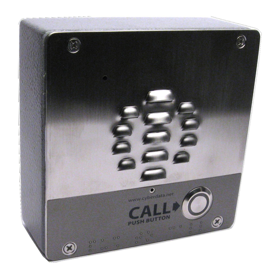
(1) V3 Intercom
Assembly
Quick Reference
Quick Reference
Installation Quick Reference
VoIP V3 Intercom
SIP Compliant
011186
Parameter
Factory Default Setting
IP Addressing
DHCP
a
IP Address
10.10.10.10
Web Access Username
admin
Web Access Password
admin
a
Subnet Mask
255.0.0.0
a
Default Gateway
10.0.0.1
a. Default if there is not a DHCP server present.
802.3af Compliant Ethernet Switch
1
2
3
4
5
6
VoIP Intercom
VoIP Intercom
(1) T-15H Torx Key
Optional Accessories
(for gooseneck mounting)
(4) Carriage bolt nuts
(4) Security Torx Screw
(4) Carriage bolts
(4) Carriage bolt washers
930471H
IP Phone
IP PBX Server
Optional Accessories
(1) Spacer for half-inch set conduit connector
(1) 531085B hole plug assembly
© 2015, CyberData Corporation, ALL RIGHTS RESERVED
Advertisement

Related Manuals for CyberData 011186


Summary of Contents for CyberData 011186
- Page 1 RMA Department: (831) 373-2601 ext. 136 RMA Email: RMA@CyberData.net Phone: 831-373-2601 (4) Carriage bolt washers Fax: 831-373-4193 RMA Status: http://support.cyberdata.net/ http://www.cyberdata.net/ Warranty Information: http://support.cyberdata.net/ © 2015, CyberData Corporation, ALL RIGHTS RESERVED 930471H Quick Reference Quick Reference 930471H © 2015, CyberData Corporation, ALL RIGHTS RESERVED...
- Page 2 Network PoE power. Use of Optional Shroud On Optional Shroud On these contacts for any other purpose will damage the device and void the product warranty. © 2015, CyberData Corporation, ALL RIGHTS RESERVED 930471H Quick Reference Quick Reference 930471H...
Need help?
Do you have a question about the 011186 and is the answer not in the manual?
Questions and answers