CyberData RAL 9003 Operation Manual
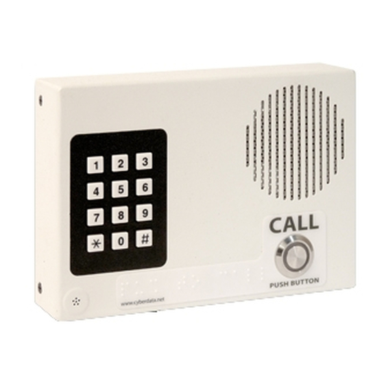
Voip indoor intercom with keypad, ral 9003, signal white color
Hide thumbs
Also See for RAL 9003:
- Installation quick reference (2 pages) ,
- Operation manual (126 pages) ,
- Operation manual (80 pages)
Table of Contents
Advertisement
Quick Links
Advertisement
Table of Contents

Subscribe to Our Youtube Channel
Related Manuals for CyberData RAL 9003


Summary of Contents for CyberData RAL 9003
- Page 1 The IP Endpoint Company VoIP Indoor Intercom with Keypad Operations Guide Part #011113*, RAL 9003, Signal White Color *Replaces #011078 Document Part #930323J for Firmware Version 6.3.0 CyberData Corporation 3 Justin Court Monterey, CA 93940 (831) 373-2601...
- Page 2 CyberData Corporation. This manual, and the products, software, firmware, and/or hardware described in this manual are the property of CyberData Corporation, provided under the terms of an agreement between CyberData Corporation and recipient of this manual, and their use is subject to that agreement and its terms.
-
Page 3: Important Safety Instructions
Electrical Hazard: This product should be installed by a licensed electrician according to all local electrical and building codes. GENERAL ALERT Warning Electrical Hazard: To prevent injury, this apparatus must be securely attached to the floor/wall in accordance with the installation instructions. GENERAL ALERT CyberData Corporation 930323J Operations Guide... - Page 4 Potential safety hazards are identified in this manual through the use of words Danger, Warning, and Caution, the specific hazard type, and pictorial alert icons. CyberData Corporation 930323J Operations Guide...
- Page 5 Revision Information Revision 930323J, which was released on November 13, 2012, corresponds to firmware version 6.3.0, and has the following changes: • Updates Table 2-21, "Command Interface Post Commands". Operations Guide 930323J CyberData Corporation...
-
Page 6: Table Of Contents
C.4.1 Warranty & RMA Returns within the United States ............72 C.4.2 Warranty & RMA Returns Outside of the United States ............ 72 C.4.3 Spare in the Air Policy ......................72 C.4.4 Return and Restocking Policy ....................73 C.4.5 Warranty and RMA Returns Page ..................73 Operations Guide 930323J CyberData Corporation... - Page 7 Index Operations Guide 930323J CyberData Corporation...
-
Page 8: Chapter 1 Product Overview
To identify the VoIP Indoor Intercom with Keypad, look for a model number label similar to the one shown in Figure 1-1. The model number on the label should be 011113. Figure 1-1. Model Number Label WWW.CYBERDATA.NET VoIP INTERCOM WITH KEYPAD, INDOOR,RoHS COMPLIANT 011113A / 021039G 113000001 Model number Operations Guide 930323J CyberData Corporation... -
Page 9: Typical System Installation
Electrical Hazard: This product should be installed by a licensed electrician according to all local electrical and building codes. GENERAL ALERT Warning Electrical Hazard: To prevent injury, this apparatus must be securely attached to the floor/wall in accordance with the installation instructions. GENERAL ALERT Operations Guide 930323J CyberData Corporation... -
Page 10: Product Features
One dry contact relay for auxiliary control ● Autoprovisioning ● Configurable audio files ● Night Ringer ● Three year warranty ● Peer-to-peer capable ● Door closure and tamper alert signal ● Optional Torx screws with driver kit Operations Guide 930323J CyberData Corporation... -
Page 11: Supported Protocols
G711, A-law and µ-law Regulatory Compliance FCC Class A, UL 60950 Dimensions 6.5” x 4.5” x 1.5” (H x W x D) Warranty 2 years limited Part Number 011113 Auxiliary Relay 1A at 30 VDC Operations Guide 930323J CyberData Corporation... -
Page 12: Dimensions
Product Overview How to Identify This Product 1.7 Dimensions Figure 1-3. Dimensions 1.6 [40] 6.5 [165] DIMENSIONS ARE IN INCHES [MILLIMETER] Operations Guide 930323J CyberData Corporation... -
Page 13: Chapter 2 Installing The Voip Indoor Intercom With Keypad
2.1 Parts List Table 2-1 illustrates the parts for the VoIP Indoor Intercom with Keypad. Table 2-1. Parts List Quantity Part Name Illustration VoIP Indoor Intercom with Keypad Assembly Installation Quick Reference Guide Mounting Accessory Kit Operations Guide 930323J CyberData Corporation... -
Page 14: Voip Indoor Intercom With Keypad Setup
DTMF tones generated from the phone being called. The DTMF tones are selectable from the web interface as well. Warning Electrical Hazard: The VoIP Intercom enclosure is not rated for any AC voltages. GENERAL ALERT Operations Guide 930323J CyberData Corporation... -
Page 15: Identifying The Connector Locations And Functions
POWER SUPPLY MAX. 30 VDC @ 1A Auxiliary Relay Wiring Contacts 2.2.3 Identifying the Connector Locations and Functions Figure 2-3 through Figure 2-5 Table 2-2 through Table 2-4 to identify the connector locations and functions. Operations Guide 930323J CyberData Corporation... - Page 16 Installing the VoIP Indoor Intercom with Keypad Identifying the Connector Locations and Functions Figure 2-3. Connector Locations Table 2-2. Connector Functions Connector Function PoE Network Connection (RJ-45 ethernet) Terminal Block (see Figure 2-1) RTFM (see Section 2.2.6, "RTFM Button") Operations Guide 930323J CyberData Corporation...
- Page 17 Installing the VoIP Indoor Intercom with Keypad Identifying the Connector Locations and Functions Figure 2-4. Connector Locations Table 2-3. Connector Functions Connector Function LED Interface Microphone Interface Speaker Interface Keypad Interface Operations Guide 930323J CyberData Corporation...
- Page 18 Audio Enable Factory only Phy Mode Not Used Phy Mode Not Used Phy Mode Not Used JP10 Intrusion Disable Jumper Placing a jumper on JP10 will disable the intrusion detection circuit. JP11 Option Jumper Not used Operations Guide 930323J CyberData Corporation...
-
Page 19: Call Button And Indicator Light
When you plug in the Ethernet cable or power supply: • The square, green Link light above the Ethernet port indicates that the network connection has been established (see Figure 2-7). The Link light changes color to confirm the auto-negotiated baud rate: Operations Guide 930323J CyberData Corporation... -
Page 20: Rtfm Button
Management (RTFM) button (see SW1 in Figure 2-8) on the Intercom board to announce and confirm the Intercom’s IP Address and test that the audio is working. Note You must do this test prior to final assembly. Operations Guide 930323J CyberData Corporation... -
Page 21: Announcing The Ip Address
The device will use DHCP to obtain the new IP address (DHCP-assigned address or default to 10.10.10.10 if a DHCP server is not present). Note Pressing and holding the RTFM button for longer than five seconds will restore the device to the factory default settings. Operations Guide 930323J CyberData Corporation... -
Page 22: Adjust The Volume
The device will use DHCP to obtain the new IP address (DHCP-assigned address or default to 10.10.10.10 if a DHCP server is not present). Figure 2-9. RTFM Button RTFM 2.2.7 Adjust the Volume You can adjust the volume through the Device Configuration Page. Operations Guide 930323J CyberData Corporation... -
Page 23: Configure The Intercom Parameters
Description Link to the Home page. Link to the Device Configuration page. Link to the Networking page. Link to the SIP Configuration page. Link to the Button Configuration page. Link to the Nightringer Configuration page. Operations Guide 930323J CyberData Corporation... -
Page 24: Log In To The Configuration Home Page
Make sure that the PC is on the same IP network as the Intercom. Note You may also download CyberData’s VoIP Discovery Utility program which allows you to easily find and configure the default web address of the CyberData VoIP products. - Page 25 Log in to the Configuration Home Page 2. When prompted, use the following default Web Access Username and Web Access Password to access the Home Page (Figure 2-10): Web Access Username: admin Web Access Password: admin Figure 2-10. Home Page Operations Guide 930323J CyberData Corporation...
-
Page 26: Configure The Device Parameters
Note: You need to reboot for changes to take effect. Click on the Reboot button to reboot the system. 2.3.3 Configure the Device Parameters 1. Click the Device Configuration button to open the Device Configuration page. See Figure 2-11. Operations Guide 930323J CyberData Corporation... - Page 27 Installing the VoIP Indoor Intercom with Keypad Configure the Device Parameters Figure 2-11. Device Configuration Page Operations Guide 930323J CyberData Corporation...
- Page 28 Click on the Test Audio button to do an audio test. When the Test Audio button is pressed, you will hear a voice message for testing the device audio quality and volume. Operations Guide 930323J CyberData Corporation...
-
Page 29: Configure The Network Parameters
Click on the Reboot button to reboot the system. 3. After changing the parameters, click the Save button. 2.3.4 Configure the Network Parameters 1. Click the Networking button to open the Network Configuration page (Figure 2-12). Operations Guide 930323J CyberData Corporation... - Page 30 Installing the VoIP Indoor Intercom with Keypad Configure the Network Parameters Figure 2-12. Network Configuration Page Operations Guide 930323J CyberData Corporation...
-
Page 31: Configure The Sip Parameters
5. From a system on the same network as the Intercom, open a browser with the new IP address of the Intercom. 2.3.5 Configure the SIP Parameters 1. Click SIP Config to open the SIP Configuration page (Figure 2-13). Note For specific server configurations, go to the following website address: http://www.cyberdata.net/support/server/index.html Operations Guide 930323J CyberData Corporation... - Page 32 Installing the VoIP Indoor Intercom with Keypad Configure the SIP Parameters Figure 2-13. SIP Configuration Page Operations Guide 930323J CyberData Corporation...
- Page 33 Unregister on Reboot* When selected, on boot, the device will first register with a SIP server with a expiration delay of 0 seconds. This has the effect of unregistering any current devices on this extension. Operations Guide 930323J CyberData Corporation...
- Page 34 Click the Save button to save your configuration settings. Note: You need to reboot for changes to take effect. Click on the Reboot button to reboot the system. 3. After changing the parameters, click Save Settings. Operations Guide 930323J CyberData Corporation...
- Page 35 There is no way to place a point-to-point call in Telephone Dial Mode or Cellphone Dial Mode. The Intercom can receive point-to-point calls in any mode. The delayed DTMF functionality is available in the Point-to-Point Mode. Note Note Establishing point-to-point SiP calls may not work with all phones. Operations Guide 930323J CyberData Corporation...
-
Page 36: Configure The Button Parameters
Figure 2-14. SIP Configuration Page Set to Point-to-Point Mode Intercom is set to NOT register with a SiP server 2.3.6 Configure the Button Parameters 1. Click the Button Config button to open the Button Configuration page. See Figure 2-15. Operations Guide 930323J CyberData Corporation... - Page 37 Installing the VoIP Indoor Intercom with Keypad Configure the Button Parameters Figure 2-15. Button Configuration Page Operations Guide 930323J CyberData Corporation...
- Page 38 Installing the VoIP Indoor Intercom with Keypad Configure the Button Parameters Figure 2-16. Button Configuration Page (continued) Operations Guide 930323J CyberData Corporation...
- Page 39 Keypad (0 through 9, *, and #) Enter the desired dial-out extension number (64 character limit). Note: For information about dial-out extension strings and DTMF tones, see Section 2.3.6.1, "Dial Out Extension Strings and DTMF Tones (using rfc2833)". Operations Guide 930323J CyberData Corporation...
- Page 40 You can still use the # key but it is not necessary. For information about how to instantly triggering a dialout call or security code, see Section 2.3.6.2, "Triggering a Dialout Call or Security Code". Operations Guide 930323J CyberData Corporation...
- Page 41 Click the Save button to save your configuration settings. Note: You need to reboot for changes to take effect. Click on the Reboot button to reboot the system. 3. After changing the parameters, click the Save button. Operations Guide 930323J CyberData Corporation...
- Page 42 Allow Telephone Dialout Option Disabled (in security mode with default security settings) Input Resulting Action Dialing 1234560 The device will activate the relay for Security Code 0 for 6 seconds. (and waiting for several seconds) Operations Guide 930323J CyberData Corporation...
-
Page 43: Configure The Night Ringer Parameters
The Nightringer is designed to be used in buildings where calls made after hours are directed to a ring group. 1. Click on the Nightringer button to open the Nightringer Configuration page. See Figure 2-17. Figure 2-17. Nightringer Configuration Setup Operations Guide 930323J CyberData Corporation... -
Page 44: Configure The Sensor Parameters
• Flash the LED until the sensor is deactivated (roughly 10 times/second) • Activate the relay until the sensor is deactivated • Loop an audio file out of the Intercom speaker until the sensor is deactivated Operations Guide 930323J CyberData Corporation... - Page 45 Configure the Sensor Parameters • Call a preset extension and play a pre-recorded audio file (once) Note Calling a preset extension can be set up as a point-to-point call, but currently can't send delayed DTMF tones. Operations Guide 930323J CyberData Corporation...
- Page 46 2. On the Sensor Configuration page, enter values for the parameters indicated in Table 2-15. Table 2-15. Sensor Configuration Parameters Web Page Item Description Door Sensor Settings Door Sensor Normally Closed Select the inactive state of the door sensors. Operations Guide 930323J CyberData Corporation...
-
Page 47: Configure The Multicast Parameters
Multicast addresses specify an arbitrary group of IP hosts that have joined the group and want to receive traffic sent to the group. Group members send IGMP messages to their local multicast routers, allowing the group traffic traversal from the source. Operations Guide 930323J CyberData Corporation... - Page 48 Multicast configuration provides the ability to join up to 10 paging zones. A paging zone can consist of one, or many, CyberData multicast group-enabled devices. There is no limit to how many devices can be in a given paging zone. Each multicast group is defined by a multicast address and port number.
- Page 49 SIP calls, multicast streams, ring tones, ringback tones, and nightring tones are all prioritized. Ringtones and Ringtones all play at the same priority level. This means that it is possible to have a nightring tone Nightringtones and a normal ringtone playing at the same time. Operations Guide 930323J CyberData Corporation...
-
Page 50: Configure The Audio Parameters
The Audio Configuration page is used to add custom audio to the board. User uploaded audio will take precedence over the audio files shipped with the Intercom. 1. Click Audio Config to open the Audio Configuration page (Figure 2-20). Figure 2-20. Audio Configuration Page Operations Guide 930323J CyberData Corporation... - Page 51 Installing the VoIP Indoor Intercom with Keypad Configure the Audio Parameters Figure 2-21. Audio Configuration Page (continued) Operations Guide 930323J CyberData Corporation...
- Page 52 '9' corresponds to the spoken word “nine.” Corresponds to the spoken word “dot.” (24 character limit) Audiotest Corresponds to the message “This is the CyberData IP speaker test message...” (24 character limit) Pagetone Corresponds to a simple tone used for beep on initialization and beep on page (24 character limit).
- Page 53 The Save button will download a new user audio file to the board once you've selected the file by using the Browse button. The Save button will delete any pre-existing user- uploaded audio files. Operations Guide 930323J CyberData Corporation...
- Page 54 RIFF (little-endian) data, WAVE audio, Microsoft PCM, 16 bit, mono 8000 Hz You can use the free utility Audacity to convert audio files into this format. See Figure 2-23 through Figure 2-25. Figure 2-23. Audacity 1 Figure 2-24. Audacity 2 Operations Guide 930323J CyberData Corporation...
-
Page 55: Configure The Event Parameters
Click the Event Config button to open the Event Configuration page. The Event Configuration page specifies a remote server that can be used to receive HTTP POST events when actions take place on the board. Operations Guide 930323J CyberData Corporation... - Page 56 Installing the VoIP Indoor Intercom with Keypad Configure the Event Parameters Figure 2-26. Event Configuration Page Operations Guide 930323J CyberData Corporation...
- Page 57 Click the Save button to save your configuration settings. Note: You need to reboot for changes to take effect. Click on the Test Event button to test an event. Click on the Reboot button to reboot the system. Operations Guide 930323J CyberData Corporation...
- Page 58 Here are example packets for every event: POST xmlparse_engine HTTP/1.1 Host: 10.0.3.79 User-Agent: CyberData/1.0.0 Content-Length: 197 Content-Type: application/x-www-form-urlencoded <?xml version="1.0" encoding="ISO-8859-1"?> <cyberdata NAME='CyberData VoIP Device' MAC='0020f70015b6'> <event>POWERON</event> </cyberdata> POST xmlparse_engine HTTP/1.1 Host: 10.0.3.79 User-Agent: CyberData/1.0.0 Content-Length: 199 Content-Type: application/x-www-form-urlencoded <?xml version="1.0"...
- Page 59 Installing the VoIP Indoor Intercom with Keypad Configure the Event Parameters User-Agent: CyberData/1.0.0 Content-Length: 205 Content-Type: application/x-www-form-urlencoded <?xml version="1.0" encoding="ISO-8859-1"?> <cyberdata NAME='CyberData VoIP Device' MAC='0020f70015b6'> <event>CALL_TERMINATED</event> </cyberdata> POST xmlparse_engine HTTP/1.1 Host: 10.0.3.79 User-Agent: CyberData/1.0.0 Content-Length: 197 Content-Type: application/x-www-form-urlencoded <?xml version="1.0" encoding="ISO-8859-1"?>...
- Page 60 Installing the VoIP Indoor Intercom with Keypad Configure the Event Parameters User-Agent: CyberData/1.0.0 Content-Length: 234 Content-Type: application/x-www-form-urlencoded <?xml version="1.0" encoding="ISO-8859-1"?> <cyberdata NAME='CyberData VoIP Device' MAC='0020f70015b6'> <event>RELAY_DEACTIVATED</event> </cyberdata> POST xmlparse_engine HTTP/1.1 Host: 10.0.3.79 User-Agent: CyberData/1.0.0 Content-Length: 234 Content-Type: application/x-www-form-urlencoded <?xml version="1.0" encoding="ISO-8859-1"?>...
-
Page 61: Configure The Autoprovisioning Parameters
Installing the VoIP Indoor Intercom with Keypad Configure the Autoprovisioning Parameters <cyberdata NAME='CyberData VoIP Device' MAC='0020f70015b6'> <event>INTRUSION SENSOR</event> <index>8</index> </cyberdata> 2.3.12 Configure the Autoprovisioning Parameters 1. Click the Autoprovisioning button to open the Autoprovisioning Configuration page. Figure 2-27. Figure 2-27. Autoprovisioning Configuration Page... - Page 62 Click the Save button to save your configuration settings. Note: You need to reboot for changes to take effect. Click on the Reboot button to reboot the system. 3. After changing the parameters, click the Save button. Operations Guide 930323J CyberData Corporation...
- Page 63 The board gets its autoprovisioning information from an XML-formatted file hosted from a TFTP server. CyberData will provide a template for this XML file and the user can modify it for their own use.
- Page 64 3. The board downloads and writes the firmware file again. CyberData has timed a firmware upgrade at 140 seconds. Therefore, if you suspect the board is stuck in a loop, either remove or comment out the FirmwareVersion line in the XML file and let the board boot as it normally does.
- Page 65 You can force a change to the audio files on the board by clicking Restore Default on the Audio Configuration page or by changing the autoprovisioning file with “default” set as the file name. Operations Guide 930323J CyberData Corporation...
-
Page 66: Upgrading The Firmware And Rebooting The Intercom
2.4.1 Upgrading the Firmware Note To guard against failed firmware upgrades, units shipped from CyberData with firmware version 5.1.2 and later feature a built-in "fail safe" mechanism. Note that field upgrading earlier units with v5.x.x will not allow for this feature. - Page 67 Shows the current firmware version. Use the Browse button to navigate to the location of the Intercom firmware file that you want to upload. Click on the Submit button to automatically upload the selected firmware and reboot the system. Operations Guide 930323J CyberData Corporation...
-
Page 68: Reboot The Intercom
To reboot a Intercom, log in to the web page as instructed in Section 2.3.2, "Log in to the Configuration Home Page". 1. Click Reboot (Figure 2-29). A normal restart will occur. Figure 2-29. Reboot System Section Reboot Operations Guide 930323J CyberData Corporation... -
Page 69: Command Interface
Play the "2" audio file wget --user admin --password admin --auth-no-challenge --quiet - O /dev/null "http://10.0.3.71/cgi-bin/audioconfig.cgi" --post-data "play_2=yes" Play the "3" audio file wget --user admin --password admin --auth-no-challenge --quiet - O /dev/null "http://10.0.3.71/cgi-bin/audioconfig.cgi" --post-data "play_3=yes" Operations Guide 930323J CyberData Corporation... - Page 70 Play the "Intrusion Sensor Triggered" audio file wget --user admin --password admin --auth-no-challenge --quiet - O /dev/null "http://10.0.3.71/cgi-bin/audioconfig.cgi" --post-data "play_intrusionsensortriggered=yes" Play the "Door Ajar" audio file wget --user admin --password admin --auth-no-challenge --quiet - O /dev/null "http://10.0.3.71/cgi-bin/audioconfig.cgi" --post-data "play_doorajar=yes" Operations Guide 930323J CyberData Corporation...
- Page 71 Delete the "Rebooting" audio file wget --user admin --password admin --auth-no-challenge --quiet - O /dev/null "http://10.0.3.71/cgi-bin/audioconfig.cgi" --post-data "delete_rebooting=yes" Delete the "Restoring Default" audio file wget --user admin --password admin --auth-no-challenge --quiet - O /dev/null "http://10.0.3.71/cgi-bin/audioconfig.cgi" --post-data "delete_restoringdefault=yes" Operations Guide 930323J CyberData Corporation...
- Page 72 --user admin --password admin --auth-no-challenge --quiet - O /dev/null "http://10.0.3.71/cgi-bin/sensorconfig.cgi" --post-data "intrusiontest=yes" a.Type and enter all of each http POST command on one line. b. Must be in point-to-point mode see Section 2.3.5.1, "Point-to-Point Configuration" Operations Guide 930323J CyberData Corporation...
-
Page 73: Appendix A Mounting The Indoor Voip Indoor Intercom With Keypad
#6 Plastic Anchor Table A-2. Gang Box Mounting Components (Part of the Accessory Kit) Quantity Part Name Illustration #6 x 3/8-inch Pan Head Phillips Machine Screw a.Only two screws are needed for a 1-Gang Box. Operations Guide 930323J CyberData Corporation... - Page 74 Figure A-1. Wall Mounting Option Backplate Can Be Rotated Hole in Wall to Mount on Either Sides (for Network Cable) Pre-Drilled Hole (4 Places) Sheet Metal Screw & Plastic Anchor (4 Pieces Each) Machine Screw (4 Pieces) Operations Guide 930323J CyberData Corporation...
- Page 75 Figure A-2. Gang Box Mounting Single Gang or 2 Gang Box (Not Provided) 611469B Can Be Rotated to Mount on Either Sides Drywall or Wall Cutout Mounting Screw for Gang Box (4 Pieces) Machine Screw (4 Pieces) Operations Guide 930323J CyberData Corporation...
-
Page 76: Appendix B Setting Up A Tftp Server
1. Install and start the software. 2. Select File Configure Security tab Transmit Only. 3. Make a note of the default directory name, and then move the firmware files to be uploaded to that directory. Operations Guide 930323J CyberData Corporation... -
Page 77: Appendix C Troubleshooting/Technical Support
2. Go to the support page for your product, and click on the FAQs tab. C.2 Documentation The documentation for this product is released in an English language version only. You can download PDF copies of CyberData product documentation by doing the following: 1. Go to the following URL: http://www.cyberdata.net/products/voip/digitalanalog/intercomkeypad/docs.html 2. -
Page 78: Contact Information
3 Justin Court Monterey, CA 93940 Attention: RMA "your RMA number" RMA Status Form If you need to inquire about the repair status of your product(s), please use the CyberData RMA Status form at the following web address: http://www.cyberdata.net/support/rmastatus.html Operations Guide... -
Page 79: Warranty
C.4.3 Spare in the Air Policy CyberData now offers a Spare in the Air no wait policy for warranty returns within the United States and Canada. More information about the Spare in the Air policy is available at the following web address: http://www.cyberdata.net/support/warranty/spareintheair.html... -
Page 80: Return And Restocking Policy
For End Users, please contact the company that you purchased your equipment from for their return policy. C.4.5 Warranty and RMA Returns Page The most recent warranty and RMA information is available at the CyberData Warranty and RMA Returns Page at the following web address: http://www.cyberdata.net/support/warranty/index.html... - Page 81 8, 9, 10, 11 address, configuration login 17 contact information 71 alternative power input 4, 7 contact information for CyberData 71 announcing a device’s IP address 14 current network settings 24 audio configuration 43 CyberData contact information 71...
- Page 82 66 network parameters 22 indicator light 12 nightring tones 42 installation, typical intercom system 2 nightringer settings 37 intercom configuration default IP settings 16 intercom configuration page configurable parameters 26, 60 Operations Guide 930323J CyberData Corporation...
- Page 83 71 resetting the IP address to the default 66 technical support, contact information 71 restoring factory default settings 15, 74 terminal block, 16 AWG gauge wire 7 restoring the factory default settings 15 Operations Guide 930323J CyberData Corporation...
- Page 84 & RMA returns outside of the United States 72 warranty & RMA returns within the United States 72 warranty and RMA returns page 73 warranty policy at CyberData 72 web access password 16 web access username 16 web configuration log in address 17...
Need help?
Do you have a question about the RAL 9003 and is the answer not in the manual?
Questions and answers