
Related Manuals for Moxa Technologies MiiNePort E1-SDK


Summary of Contents for Moxa Technologies MiiNePort E1-SDK
- Page 1 MiiNePort E1/E2-SDK User’s Manual Edition 2.1, November 2017 www.moxa.com/product © 2017 Moxa Inc. All rights reserved.
- Page 2 MiiNePort E1/E2-SDK User’s Manual the terms of that agreement. Copyright Notice © 2017 Moxa Inc. All rights reserved. Trademarks The MOXA logo is a registered trademark of Moxa Inc. All other trademarks or registered marks in this manual belong to their respective manufacturers. Disclaimer Information in this document is subject to change without notice and does not represent a commitment on the part of Moxa.
-
Page 3: Table Of Contents
Overview ............................1-2 Package Checklist ..........................1-2 Product Features ..........................1-2 Panel Layout ............................1-3 MiiNePort E1-SDK Evaluation Board Panel Layout ................1-3 MiiNePort E2-SDK Evaluation Board Panel Layout ................1-4 Block Diagram ............................ 1-5 For MiiNePort E1-SDK Module ....................... 1-5 For MiiNePort E2-SDK Module ....................... - Page 4 NetEZ Technologies ........................... 6-1 SCM (Serial Command Mode) ....................... 6-2 EXTrigger (External Trigger) ........................ 6-3 EZPower ............................6-4 Introduction to SCM (Serial Command Mode) Command Set ............. A-1 Command/Reply Format ........................A-2 Single Line Command Format ....................... A-2 Single Line Reply Format ......................A-2 Head and Tail Format ........................
-
Page 5: Introduction
The following topics are covered in this chapter: Overview Package Checklist Product Features MiiNePort E1-SDK Evaluation Board Panel Layout MiiNePort E2-SDK Evaluation Board Panel Layout Block Diagram For MiiNePort E1-SDK Module For MiiNePort E2-SDK Module... -
Page 6: Overview
Package Checklist Available Models: • MiiNePort E1-SDK: Software Development Kit for the MiiNePort E1 Series, MiiNePort E1 module included • MiiNePort E2-SDK: Software Development Kit for the MiiNePort E2 Series, MiiNePort E2 module included Package Checklist: •... -
Page 7: Panel Layout
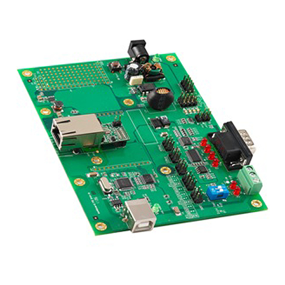
MiiNePort E1/E2-SDK Introduction Panel Layout MiiNePort E1-SDK Evaluation Board Panel Layout Number Description MiiNePort E1 Module Location USB Type B Connector (Debug) Configurable Pin Jumper Digital Input Switch Digital Output LED Digital IO Terminal Block Serial Port Status LED DB9 Male Connector... -
Page 8: Miineport E2-Sdk Evaluation Board Panel Layout
MiiNePort E1/E2-SDK Introduction ATTENTION Before you manipulate the jumpers, be sure to disconnect the power first. MiiNePort E2-SDK Evaluation Board Panel Layout Number Description MiiNePort E2 Module Location Ethernet RJ45 Connector Serial Interface Jumper Power Switch Power Jack Power & Ready LED DB9 Male Connector Serial Port Status LED Digital IO Terminal Block... -
Page 9: Block Diagram
MiiNePort E1/E2-SDK Introduction Ethernet Port Pins for MiiNePort E1/E2-SDK Modules RJ45 Signal Serial Pin Signals for the MiiNePort E1/E2-SDK Evaluation Board DB9 Male RS-232 2-wire RS-485 – – Data+ Data- – – – Block Diagram For MiiNePort E1-SDK Module... -
Page 10: For Miineport E2-Sdk Module
MiiNePort E1/E2-SDK Introduction For MiiNePort E2-SDK Module LED Indicators MiiNePort E1-SDK Series Modules Color Description Green 100BASE-TX Link Activity (constant on when link exists, blinks when data transmitting) Left Amber 10BASE-T Link Activity (constant on when link exists, blinks when data transmitting) - Page 11 MiiNePort E1/E2-SDK Introduction MiiNePort E2-SDK Evaluation Board LED Name Color Description Power 1. Power is off 2. Power error 3. System error Green, Steady On Indicates that the power is on. Ready Green, Blinking every 1 1. The device server has been located by NPort search utility’s sec.
-
Page 12: Getting Started
Getting Started This chapter includes information about how to install MiiNePort E1/E2-SDK modules for development and testing. The following topics are covered in this chapter: Wiring Precautions Selecting the Serial Interface Connecting Power Connecting MiiNePort USB to PC ... -
Page 13: Wiring Precautions
MiiNePort E2-SDK: To use an RS-232 serial interface, place the 6-pin jumper on JP13. RS-485 MiiNePort E1-SDK: To use an RS-485 serial interface, place the 2-pin jumper on the middle two pins of JP15 or the right-most two pins of JP16 (labeled as 485EN), and place the 6-pin jumper on JP20. -
Page 14: Connecting Power
Getting Started Connecting Power For MiiNePort E1-SDK Evaluation Board Layout Connect the 12-48 VDC power line with the power jack of the evaluation board. If the power is properly supplied, the power LED (D15, as shown in the following figure) on the evaluation board will show a solid red color until the system is ready, at which time the ready LED on the module will show a solid green color. - Page 15 MiiNePort E1/E2-SDK Getting Started Number Description MiiNePort E1 Module Location USB Type B Connector (Debug) Configurable Pin Jumper Digital Input Switch Digital Output LED Digital IO Terminal Block Serial Port Status LED DB9 Male Connector Serial Interface Jumper Power LED Power Jack Restart Button Circuit Pad...
-
Page 16: Connecting To The Network
COM port on the evaluation board. Digital I/O Channel Settings For MiiNePort E1-SDK Evaluation Board Layout Each module has three digital I/O (DIO) channels. (Refer to the Pin Assignments section above for the module’s configurable DIO pin description. Refer to Configurable Pin Jumpers to select the corresponding setting on the evaluation board.) All three DIO channels may be configured by software. -
Page 17: Schematic Design Guide
MiiNePort E1/E2-SDK Getting Started For MiiNePort E2-SDK Evaluation Board Layout Each module has four digital I/O (DIO) channels. (Refer to the Pin Assignment section in Chapter 1 for the module’s configurable DIO pin descriptions. Refer to the Evaluation Board Layout section in Chapter 1 to select corresponding settings on the evaluation board.) All four DIO channels can be configured by software. -
Page 18: Choosing The Proper Operation Mode
Choosing the Proper Operation Mode In this chapter, we will describe the operation modes supported by MiiNePort E1/E2-SDK modules. Modes are available for COM port mapping from the host computer, as well as operation modes for TCP/IP protocols. After choosing the operation mode in this chapter, refer to subsequent chapters for configuration details. The following topics are covered in this chapter: ... -
Page 19: Overview
MiiNePort E1/E2-SDK Choosing the Proper Operation Mode Overview MiiNePort E1/E2-SDK modules act as a bridge to connect your serial devices to the Ethernet. The built-in TCP/IP stack frees you from the tedious task of programming networking protocols. With one step you can choose the proper operation mode, and then use your computer to access, manage, and configure your serial devices from anywhere in the world over the Internet. -
Page 20: Ethernet Modem Mode
MiiNePort E1/E2-SDK Choosing the Proper Operation Mode Ethernet Modem Mode Ethernet Modem mode is designed for use with legacy operating systems, such as MS-DOS, that do not support TCP/IP Ethernet. By connecting the properly configured MiiNePort serial port to the MS-DOS computer’s serial port, it is possible to use legacy software to transmit data over the Ethernet when the software was originally designed to transmit data over a modem. -
Page 21: Utility Console And Driver Installation
Utility Console and Driver Installation This chapter describes the installation of the MiiNePort E1/E2-SDK’s utilities, which are used to perform simple configurations and driver installations. The following topics are covered in this chapter: Device Search Utility (DSU) Installing the Device Search Utility ... -
Page 22: Device Search Utility (Dsu)
MiiNePort E1/E2-SDK Utility Console and Driver Installation Device Search Utility (DSU) Installing the Device Search Utility 1. Click the INSTALL UTILITY button in the MiiNePort E1/E2-SDK (Installation CD) auto-run window to install the Device Search Utility. Once the program starts running, click Yes to proceed. 2. - Page 23 MiiNePort E1/E2-SDK Utility Console and Driver Installation 4. Select the additional tasks you would like to set up to be performed while installing DSU; then, click Next. 5. The installer will display a summary of the installation options. Click Install to begin the installation. The setup window will report the progress of the installation.
-
Page 24: Device Search Utility Configuration
MiiNePort E1/E2-SDK Utility Console and Driver Installation 6. Click Finish to complete the installation of the Device Search Utility. Device Search Utility Configuration The Broadcast Search function is used to locate all MiiNePort E1/E2-SDK modules that are connected to the same LAN as your computer. -
Page 25: Nport Windows Driver Manager
MiiNePort E1/E2-SDK Utility Console and Driver Installation 3. When the search is complete, all MiiNePort E1/E2-SDK modules that were located will be displayed in the Device Search Utility window. 4. To modify the configuration of the highlighted MiiNePort E1/E2-SDK, click the Console icon to open the web console. - Page 26 MiiNePort E1/E2-SDK Utility Console and Driver Installation 3. Click Browse to select the destination directory and then click Next to install program files to the directory displayed in the input box. 4. Click Next to install the program’s shortcuts in the appropriate Start Menu folder. 5.
-
Page 27: Using Nport Windows Driver Manager
MiiNePort E1/E2-SDK Utility Console and Driver Installation 6. Click Finish to complete the installation of NPort Windows Driver Manager. Using NPort Windows Driver Manager After you have installed the NPort Windows Driver Manager, you can set up the MiiNePort E1/E2-SDK serial port, which is connected to the device mainboard, as remote COM ports for your PC host. - Page 28 MiiNePort E1/E2-SDK Utility Console and Driver Installation 4. Alternatively, you can select Input Manually and then manually enter the MiiNePort E1 module’s IP Address, 1st Data Port, 1st Command Port, and Total Ports to which COM ports will be mapped. Click OK to proceed to the next step.
-
Page 29: Command Line Installation/Removal
MiiNePort E1/E2-SDK Utility Console and Driver Installation Command Line Installation/Removal The NPort Windows Driver Manager v1.19 and above comes with command-line script tool – npcli.exe for installation, removal of the driver, and configuring NPort driver functions. After successfully installing the NPort Windows Driver Manager v1.19 (or above), the default file path is C:\Program Files\NPortDrvManager as shown below. - Page 30 MiiNePort E1/E2-SDK Utility Console and Driver Installation The usage instructions will show up for user’s reference. ------------------------------------------------------------------------------ NPort Command-Line Interface Ver2.0 Build 16052400 ------------------------------------------------------------------------------ Usage: 1. NPort Driver operation: npcli /driver [/install | /uninstall | /upgrade] [PATH_NAME] /install Install specified driver to host. /uninstall Uninstall current installed driver from host.
-
Page 31: Linux Real Tty Drivers
MiiNePort E1/E2-SDK Utility Console and Driver Installation /password moxa npcli /device /apply 1 Note: Npcli.exe requires an administrator privilege to change device settings. It support only IPv4 and it must be run under Windows XP and later versions. Linux Real TTY Drivers Real TTY drivers are provided to map Linux host TTY ports to MiiNePort serial (TTL) ports. -
Page 32: Removing Mapped Tty Ports
MiiNePort E1/E2-SDK Utility Console and Driver Installation Mapping TTY ports automatically To map TTY ports automatically, you may execute mxaddsvr with just the IP address and number of ports, as in the following example: # cd /usr/lib/npreal2/driver # ./mxaddsvr 192.168.3.4 16 In this example, 16 TTY ports will be added, all with IP 192.168.3.4, with data ports from 950 to 965 and command ports from 966 to 981. -
Page 33: Installing The Unix Driver
MiiNePort E1/E2-SDK Utility Console and Driver Installation Installing the UNIX Driver Log in to UNIX and create a directory for the Moxa TTY. To create a directory named /usr/etc, execute the command: # mkdir –p /usr/etc Copy moxattyd.tar to the directory you created. For the /usr/etc directory, execute the following commands: # cp moxattyd.tar /usr/etc # cd /usr/etc... - Page 34 MiiNePort E1/E2-SDK Utility Console and Driver Installation Adding an additional server Modify the text file moxattyd.cf to add an additional server. User may use vi or any text editor to modify the file. For more configuration information, refer to moxattyd.cf, which contains detailed descriptions of the various configuration parameters.
-
Page 35: Miineport Ide Development Tool
MiiNePort IDE Development Tool The following topics are covered in this chapter: Installing MiiNePort IDE Starting MiiNePort IDE Create MiiNePort-SDK Project RealCOM Mode Ethernet Modem Mode Sample Application Data Packing Serial Command Mode ... -
Page 36: Installing Miineport Ide
MiiNePort E1/E2-SDK MiiNePort IDE Development Tool Installing MiiNePort IDE Eclipse is an open source community, whose projects are focused on building an open development platform comprised of extensible frameworks, tools and runtimes for building, deploying, and managing software across the lifecycle. MOXA provides an Eclipse-based integrated software development tool and a step-by-step source-level debugger, which is called MiiNePort IDE. - Page 37 MiiNePort E1/E2-SDK MiiNePort IDE Development Tool 4. When the Select Destination Location window appears, click Next to continue. You may change the destination directory by first clicking on Browse..5. In this page, you can select what components you would like to install, then click Next.
- Page 38 MiiNePort E1/E2-SDK MiiNePort IDE Development Tool 6. Then creating the program’s shortcuts. When the Select Destination Location window appears, click Next to continue. You may change the destination directory by first clicking on Browse..7. Click Next to start copying the software files.
- Page 39 MiiNePort E1/E2-SDK MiiNePort IDE Development Tool 8. A progress bar will appear. The procedure should take only a few seconds to complete. 9. A message will indicate that MiiNePort IDE is successfully installed. 10. You may also open MiiNePort IDE through Start Programs MOXA MiiNePort-SDK MiiNePort-IDE, as shown below.
-
Page 40: Starting Miineport Ide
MiiNePort E1/E2-SDK MiiNePort IDE Development Tool Starting MiiNePort IDE MiiNePort IDE is an Eclipse-based integrated software development tool and a step-by-step source-level debugger that is used to configure the MiiNePort-SDK. Before running MiiNePort IDE, make sure that the MiiNePort-SDK device is connected to your PC. Please refer to Chapter 2 for more details. - Page 41 1. MiiNePort E1 2. MiiNePort E2 Kernel Version SDK version For MiiNePort E1-SDK Parameter Description For the 3 configurable pins (Pin 6, 7, and 8), refer to Chapter 1: Pin Assignments for their default settings and change to the appropriate function for your application.
-
Page 42: Realcom Mode
MiiNePort E1/E2-SDK MiiNePort IDE Development Tool The next page is regarding serial to Ethernet application, data packing and serial command mode. RealCOM Mode ATTENTION To use RealCOM mode, refer to Chapter 6: Utility Console and Driver Installation to install the RealCOM driver on Windows or Linux. -
Page 43: Ethernet Modem Mode
MiiNePort E1/E2-SDK MiiNePort IDE Development Tool Max connection is used when the device needs to receive data from different hosts simultaneously. The factory default only allows 1 connection at a time. When Max Connection is set to 1, the RealCOM driver on the specific host has full control. -
Page 44: Sample Application
MiiNePort E1/E2-SDK MiiNePort IDE Development Tool TCP alive check time Setting Factory Default Recommended Setting 0 to 99 min 7 min Optional 0 min: The TCP connection is not closed due to an idle TCP connection. 1 to 99 min: The module automatically closes the TCP connection if there is no TCP activity for the given time. After the connection is closed, the module starts listening for another host’s TCP connection. -
Page 45: Data Packing
MiiNePort E1/E2-SDK MiiNePort IDE Development Tool Data Packing Packet length Setting Factory Default Recommended Setting 0 to 1024 bytes 0 byte Required The Packet length setting refers to the maximum amount of data that is allowed to accumulate in the serial port buffer before sending. - Page 46 MiiNePort E1/E2-SDK MiiNePort IDE Development Tool The delimiter process field determines how the data is handled when a delimiter is received. Delimiter 1 must be enabled for this field to have effect. If Delimiters 1 and 2 are both enabled, both characters must be received for the delimiter process to take place.
-
Page 47: Serial Command Mode
MiiNePort E1/E2-SDK MiiNePort IDE Development Tool Serial Command Mode SCM (Serial Command Mode) uses serial communication between the MiiNePort E1 and your device’s main system to configure the MiiNePort E1, usually during device operation. For more details about SCM commands, refer to Chapter 7: NetEZ Technologies. - Page 48 MiiNePort E1/E2-SDK MiiNePort IDE Development Tool The Next page is network settings, you can assign IP configuration in this page. Device name Setting Factory Default Recommended Setting 1 to 40 characters [model name]_[Serial No.] Optional This option can be used to specify the location or application of the module, which may be useful when managing more than one module on the network.
- Page 49 MiiNePort E1/E2-SDK MiiNePort IDE Development Tool Netmask Setting Factory Default Recommended Setting E.g., 255.255.255.0 255.255.255.0 Required A subnet mask represents all the network hosts at one geographic location, in one building, or on the same local area network. When a packet is sent out over the network, the module will use the subnet mask to check whether the host specified in the packet is on a local network segment.
- Page 50 MiiNePort E1/E2-SDK MiiNePort IDE Development Tool Baudrate Setting Factory Default Recommended Setting 50 bps to 921.6 Kbps 115200 Required IP configuration is a required field. The default setting is Static. ATTENTION Baudrate 460800 and 921600 are for High speed model only. If you don’t want to use High speed mode, please remove jumper first.
-
Page 51: Web Console
MiiNePort E1/E2-SDK MiiNePort IDE Development Tool MOXA provides a lot of applications to customers; as long as you check the checkbox, the desired application will be applied into your customized firmware. Web Console The Web Console is the most user-friendly way to configure the MiiNePort device. We use the Web Console interface to introduce the functions. -
Page 52: Cli
MiiNePort E1/E2-SDK MiiNePort IDE Development Tool For telnet/serial console access, MiiNePort device provides Command-Line Interface (CLI) to do some configuration or monitor work of the device, such as network configuration, serial parameter configuration, etc. The programmer can build user-defined CLI by using system CLI APIs, and a function is provided to add the user-defined CLI to the command list. -
Page 53: Tftp Server
MiiNePort E1/E2-SDK MiiNePort IDE Development Tool A write community name is a plain-text password mechanism that is used to authenticate queries to agents of managed network devices. Description Setting Factory Default Recommended Setting 0 to 40 characters None Optional Contact Setting Factory Default Recommended Setting... -
Page 54: Cpu Monitor
MiiNePort E1/E2-SDK MiiNePort IDE Development Tool Time server IP/name 1/2: Setting Factory Default Recommended Setting 0 to 40 characters None Required Time offset: Setting Factory Default Recommended Setting -720~720 min Optional Time server query period: Setting Factory Default Recommended Setting >30 Optional CPU Monitor... -
Page 55: Wizards
MiiNePort E1/E2-SDK MiiNePort IDE Development Tool Wizards Moxa provides wizards to help you modify source codes. Then MiiNePort IDE can create the functions automatically. Below is the list of wizards (You can find it on the tool bar): From the left to right, they are: •... - Page 56 MiiNePort E1/E2-SDK MiiNePort IDE Development Tool Select the location you want to add command. First, click Add Node to add a node. A window will pop up, you can edit node name and node brief. And then click the Confirm button. 5-22...
- Page 57 MiiNePort E1/E2-SDK MiiNePort IDE Development Tool Then click Add Command to add a new command. Then window will show up and you have to enter Command Name, Function, and Node Brief. After you have filled in, click Confirm. Then the new command is created. You can modify and remove it. When you finish setting CLI, click the Finish button.
-
Page 58: Configuration Wizard
MiiNePort E1/E2-SDK MiiNePort IDE Development Tool Configuration Wizard This wizard is used to help to make configuration variables. You can define the attribute you need in this page. By this way, you can build up your own configuration. First, click the Add button. 5-24... - Page 59 MiiNePort E1/E2-SDK MiiNePort IDE Development Tool Then the configuration window will pop up and you can fill in the value into each filed. After determining the new attribute, please click Confirm. Then your attribute will be showed on the configuration settings list. Besides, you can modify or remove them easily.
-
Page 60: Scm Wizard
MiiNePort E1/E2-SDK MiiNePort IDE Development Tool Finally, your configuration will be saved into config_init.c. The picture below is the configuration settings we set before. SCM Wizard This wizard is used to help add SCM commands. You can add the serial command you need in this page. With these serial commands, you can configure your device to help add SCM commands. - Page 61 MiiNePort E1/E2-SDK MiiNePort IDE Development Tool Click Add button to add a new serial command. Regarding the format of serial command, please refer to appendix A Then a serial command mode window will pop up. Fill in each field. Click Confirm to add a new serial command. The result of all serial commands will be listed in the serial command list.
-
Page 62: Snmp Wizard
MiiNePort E1/E2-SDK MiiNePort IDE Development Tool Finally, your command will be saved into scmcmd.c file. You can add other behavior in this method. SNMP Wizard This wizard is used to help to add a private MIB. You can add the private MIB you need in this page. By these OIDs in private MIB, you can manage your device by SNMP protocol. - Page 63 MiiNePort E1/E2-SDK MiiNePort IDE Development Tool First, click Add button. Select the private MIB by the Browse button, and fill in this node name. After you have completed it, click Confirm. NOTE Node name is the root name you would like to generate 5-29...
- Page 64 MiiNePort E1/E2-SDK MiiNePort IDE Development Tool The private MIB will be showed on the MIB list. Then click Finish. The MiiNePort IDE will generate some get and set functions for this MIB file under snmp folder. Besides, it will also generate the file regarding your MIB file. Then you can implement the SNMP behavior you expect from these functions.
-
Page 65: User App Wizard
MiiNePort E1/E2-SDK MiiNePort IDE Development Tool User App Wizard This wizard is used to help you to create your application (subroutine). If you would like to develop your own application, you can use this wizard. It will show you how to add a new application. Fill in all fields, click Finish button. -
Page 66: Build Project
MiiNePort E1/E2-SDK MiiNePort IDE Development Tool Build project The function is used to build a customized firmware which you develop. This function can build two different types of firmware. If you select debug type, the firmware will be downloaded onto the MiiNePort. Then you can debug step by step. - Page 67 MiiNePort E1/E2-SDK MiiNePort IDE Development Tool Then the MiiNePort will create a folder which is called “Release.” Put the firmware into this folder, so that you can find your firmware in the sub-folder ‘objs’. Please copy the .rom file to your desired path. In this way, you can upgrade the firmware by the Device Search utility.
-
Page 68: Netez Technologies
NetEZ Technologies This chapter introduces the NetEZ technology family and its innovative functions. The following topics are covered in this chapter: SCM (Serial Command Mode) EXTrigger (External Trigger) EZPower... -
Page 69: Scm (Serial Command Mode)
MiiNePort E1/E2-SDK NetEZ Technologies SCM (Serial Command Mode) The MiiNePort E1/E2-SDK’s SCM (Serial Command Mode) allows the module’s parameters to be retrieved or configured through the serial port, rather than over the network. This is done through the use of specially parsed commands sent to the module through the serial port. -
Page 70: Extrigger (External Trigger)
EXTrigger (External Trigger) This function is for MiiNePort E1-SDK only. The MiiNePort E1-SDK’s EXTrigger has two functions: (1) Resetting the module to Moxa’s default configuration, and (2) Restarting the module. EXTrigger is designed to provide you with an easy network troubleshooting tool that can be used without stopping the device’s normal operation. -
Page 71: Ezpower
MiiNePort E1/E2-SDK NetEZ Technologies EXTrigger is actually an external Digital Input (DI) that can be accessed by you or your device’s end user. You can design your own application by leveraging this external DI. Contact Moxa for information about custom EXTrigger functions. -
Page 72: Introduction To Scm (Serial Command Mode) Command Set
Introduction to SCM (Serial Command Mode) Command Set The following topics are covered in this appendix: Command/Reply Format Single Line Command Format Single Line Reply Format Head and Tail Format Operation Codes Status Codes ... -
Page 73: Command/Reply Format
MiiNePort E1/E2-SDK Introduction to SCM (Serial Command Mode) Command Set Command/Reply Format Single Line Command Format Head Cmd. Parameters Tail 1 byte 1 byte 2 bytes 0 to n bytes 1 to 2 bytes Single Line Reply Format Head Cmd. Parameters Tail 1 byte... -
Page 74: Command Code
MiiNePort E1/E2-SDK Introduction to SCM (Serial Command Mode) Command Set Command Code Command Code for Getting the Configuration Device Name Command code: BN Command parameters: N/A Reply parameters: MiiNePort’s name. ?GBN System requests configured device name for this MiiNePort. !GBN0MiiNePort_E1_9527 MiiNePort reports device name as MiiNePort_E1_9527 IP configuration Command code: NC... - Page 75 MiiNePort E1/E2-SDK Introduction to SCM (Serial Command Mode) Command Set Gateway Command code: NG Command parameters: N/A Reply parameters: MiiNePort’s Gateway address. ?GNG System requests Gateway address for this MiiNePort. !GNG0255.255.255.255 MiiNePort reports Gateway address as ‘255.255.255.255’. Command code: ND Command parameters: The index (1 or 2) of DNS server.
-
Page 76: Command Codes For Retrieving Running Configuration
MiiNePort E1/E2-SDK Introduction to SCM (Serial Command Mode) Command Set Gateway Command code: NG Command parameters: MiiNePort’s Gateway address. Reply parameters: N/A ?SNG192.168.1.254 System sets Gateway as ‘192.168.1.254’. !SNG0 MiiNePort reports command executed successfully. Command code: ND Command parameters: The index (1,2) and DNS server address, separated by a semicolon (;). Reply parameters: N/A ?SND1;192.168.1.123... - Page 77 MiiNePort E1/E2-SDK Introduction to SCM (Serial Command Mode) Command Set Netmask Command code: NM Command parameters: N/A Reply parameters: MiiNePort’s Netmask address. ?RNM System requests Netmask address for this MiiNePort. !RNM0255.255.255.0 MiiNePort reports netmask as ‘255.255.255.0’. Gateway Command code: NG Command parameters: N/A Reply parameters: MiiNePort’s Gateway address.
-
Page 78: Command Codes For Viewing The Status
MiiNePort E1/E2-SDK Introduction to SCM (Serial Command Mode) Command Set Command Codes for Viewing the Status Control Command Codes PING Command code: NP Command parameters: Target host name or IP address. Reply parameters: A single minus symbol indicates the target host did not reply in 1000 milliseconds. Otherwise, one decimal number indicating the reply latency in milliseconds is returned. -
Page 79: Well-Known Port Numbers
Well-Known Port Numbers This appendix is included for your reference. Listed below are port numbers that already have a well-established use. These port numbers should be avoided when assigning a port number to your MiiNePort E1 Series module; otherwise you may experience network problems. Refer to the RFC 1700 standard for Well-Known Port Numbers or refer to the following introduction from IANA. - Page 80 MiiNePort E1/E2-SDK Well-Known Port Numbers UDP Socket Application Service Reserved Management Utility Echo Discard Active Users (systat) Daytime Any private printer server Resource Location Protocol Host name server (names server) Whois (nickname) (Login Host Protocol) (Login) Domain Name Server (domain) Trivial Transfer Protocol (TETP) Gopler Protocol Finger Protocol...
- Page 81 SNMP Agent with MIB II and RS-232 Like Groups MiiNePort E1 Series modules have SNMP (Simple Network Management Protocol) agent software built in. The software supports RFC1317 RS-232 like groups and RFC 1213 MIB-II. The following table lists the standard MIB-II groups, as well as the variable implementations for the MiiNePort E1 Series modules.
-
Page 82: Snmp Agent With Mib Ii And Rs-232 Like Groups
MiiNePort E1/E2-SDK SNMP Agent with MIB II and RS-232 Like Groups UDP MIB TCP MIB SNMP MIB UdpInDatagrams tcpRtoAlgorithm snmpInPkts UdpNoPorts tcpRtoMin snmpOutPkts UdpInErrors tcpRtoMax snmpInBadVersions UdpOutDatagrams tcpMaxConn snmpInBadCommunityNames UdpLocalAddress tcpActiveOpens snmpInASNParseErrs UdpLocalPort tcpPassiveOpens snmpInTooBigs tcpAttempFails snmpInNoSuchNames Address Translation MIB tcpEstabResets snmpInBadValues AtIfIndex... -
Page 83: Supported File Systems
Supported File Systems There are two file systems in MiiNePort-SDK for you to access via file operation APIs: ROM file system and FAT ROM File System When you create your project under MiiNePort-IDE, you can find a directory named <romfs> under your project directory, as shown in the following: All files in <romfs>... - Page 84 MiiNePort E1/E2-SDK Supported File Systems The following example uses POSIX library to write/read a file. Example:...
Need help?
Do you have a question about the MiiNePort E1-SDK and is the answer not in the manual?
Questions and answers