Moxa Technologies ioLogik E1200 Series User Manual
Hide thumbs
Also See for ioLogik E1200 Series:
- User manual (105 pages) ,
- Quick installation manual (9 pages) ,
- User manual (117 pages)

Related Manuals for Moxa Technologies ioLogik E1200 Series


Summary of Contents for Moxa Technologies ioLogik E1200 Series
- Page 1 E1200 Series User’s Manual Fifth Edition, February 2011 www.moxa.com/product © 2011 Moxa Inc. All rights reserved. Reproduction without permission is prohibited.
- Page 2 E1200 Series User’s Manual The software described in this manual is furnished under a license agreement and may be used only in accordance with the terms of that agreement. Copyright Notice Copyright ©2011 Moxa Inc. All rights reserved. Reproduction without permission is prohibited.
-
Page 3: Table Of Contents
Table of Contents Introduction ............................1-1 Product Model Information ........................1-2 Product Features ..........................1-2 Inside the Box ............................ 1-2 Product Specifications ......................... 1-3 Physical Dimensions ..........................1-7 Hardware Reference ..........................1-8 Panel Guide ..........................1-8 LED Indicators ..........................1-8 Initial Setup ............................ - Page 4 Active OPC Server Lite........................5-1 Introduction to Active OPC Server Lite ....................5-2 Active OPC Server Lite Specifications ....................5-2 Installing Active OPC Server Lite ....................5-2 Installing OPC Core Components ....................5-2 Active OPC Server Lite......................... 5-3 Main Screen Overview........................5-3 Menu Items............................
-
Page 5: Introduction
Introduction The ioLogik E1200 series is a stand-alone remote Ethernet I/O server that can connect sensors and on/off switches for automation applications over Ethernet and IP-based networks. The following topics are covered in this chapter: Product Model Information Product Features ... -
Page 6: Product Model Information
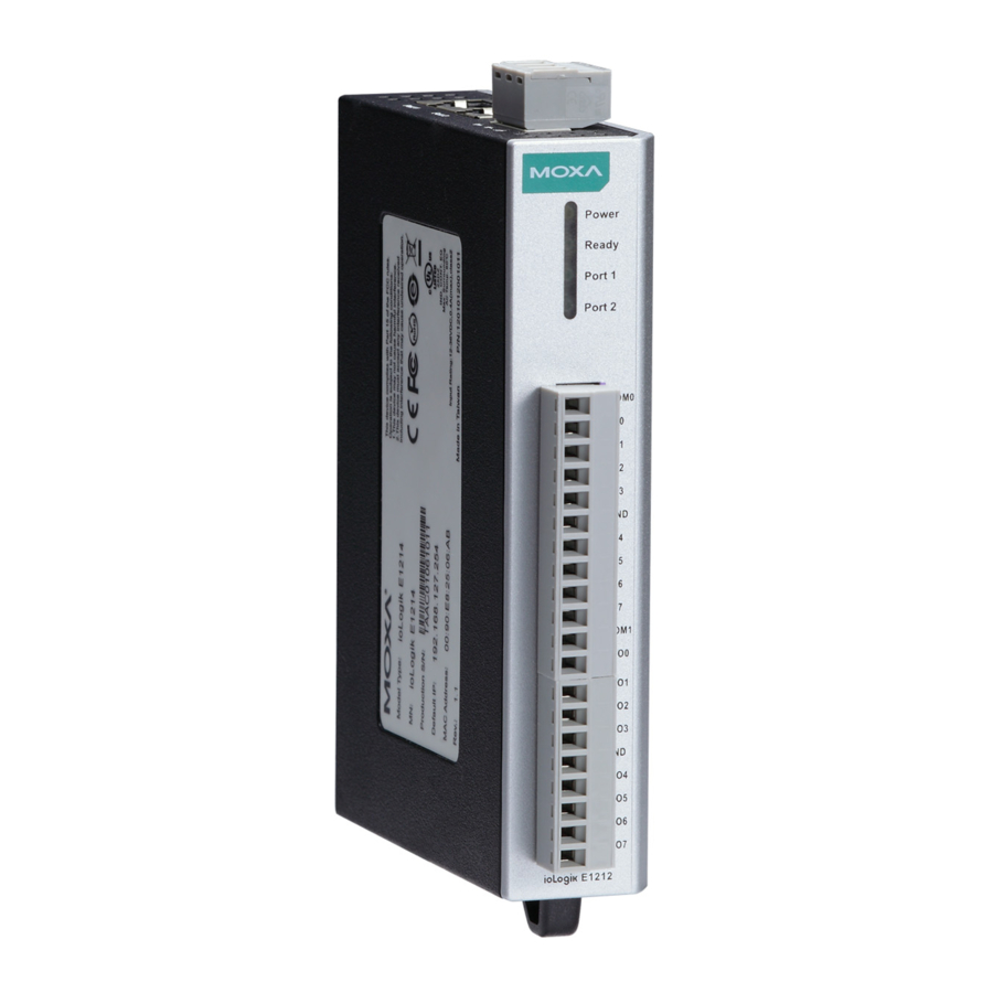
E1200 Series Introduction Product Model Information Model Description ioLogik E1210 Remote Ethernet I/O with 2-port Ethernet switch and 16 DIs ioLogik E1211 Remote Ethernet I/O with 2-port Ethernet switch and 16 DOs ioLogik E1212 Remote Ethernet I/O with 2-port Ethernet switch, 8 DIs, and 8 DIOs... -
Page 7: Product Specifications
E1200 Series Introduction Product Specifications ioLogik E1210 Digital Input Sensor Type: NPN, PNP, and Dry contact I/O Mode: DI or Event Counter Dry Contact: • Logic 0: short to GND • Logic 1: open Wet Contact: • Logic 0: 0 to 3 VDC •... - Page 8 E1200 Series Introduction Digital Output I/O Mode: DO or Pulse Output Pulse Wave Width/Frequency: 1 ms/500 Hz Over-voltage Protection: 45 VDC Over-current Protection: 2.6 A (4 channels @ 650 mA) Over-temperature Shutdown: 175°C (typical), 150°C (min.) Current Rating: 200 mA per channel...
- Page 9 E1200 Series Introduction Accuracy: ±0.1% FSR @ 25°C ±0.3% FSR @ -10 and 60°C Sampling Rate (all channels): 12 samples/sec Input Impedance: 10M ohms (minimum) Built-in Resistor for Current Input: 120 ohms Power Requirements Power Consumption: 121 mA @ 24 VDC...
- Page 10 E1200 Series Introduction Counter/Frequency: 250 Hz, power off storage Digital Output I/O Mode: DO or Pulse Output Pulse Wave Width/Frequency: 1 ms/500 Hz Over-voltage Protection: 45 VDC Over-current Protection: 2.6 A (4 channels @ 650 mA) Over-temperature Shutdown: 175°C (typical), 150°C (min.)
-
Page 11: Physical Dimensions
E1200 Series Introduction Common Specifications Ethernet: 2 x 10/100 Mbps switch ports, RJ45 Protection: 1.5 KV magnetic isolation Protocols: Modbus/TCP, TCP/IP, UDP, DHCP, Bootp, HTTP Power Requirements Power Input: 24 VDC nominal, 12 to 36 VDC Physical Characteristics Wiring: I/O cable max. 14 AWG Dimensions: 27.8 x 124 x 84 mm (1.09 x 4.88 x 3.31 in) -
Page 12: Hardware Reference
E1200 Series Introduction Hardware Reference Panel Guide NOTE The reset button restarts the server and resets all settings to factory defaults. Use a pointed object such as a straightened paper clip to hold in the reset button for 5 sec. The factory defaults will be loaded once the Ready LED turns green again. -
Page 13: Initial Setup
Initial Setup This chapter describes how to install the ioLogik E1200. The following topics are covered in this chapter: Hardware Installation Connecting the Power Grounding the ioLogik E1200 Connecting to the Network Jumper Settings I/O Wiring Diagrams ... -
Page 14: Hardware Installation
E1200 Series Initial Setup Hardware Installation Connecting the Power Connect the 12 to 36 VDC power line to the ioLogik E1200’s terminal block on the top panel. If power is properly supplied, the Power LED will glow a solid amber color. -
Page 15: Jumper Settings
E1200 Series Initial Setup Jumper Settings The ioLogik E1212, E1240, and E1242 require configuring the jumpers inside the enclosure. Remove the screw on the back panel and open the cover to configure the jumpers. DIO mode configuration is as follows (default is DO Mode) - Page 16 E1200 Series Initial Setup...
-
Page 17: Software Installation
E1200 Series Initial Setup Software Installation ioSearch is a search utility that helps the user locate ioLogik E1200 devices on the local network. Find the ioSearch utility in the Document and Software CD under Software ioSearch, or download the latest version from Moxa’s website. -
Page 18: Using The Web Console
Using the Web Console The ioLogik E1200’s main configuration and management utility is the built-in web console, which can be used to configure a wide range of options. The following topics are covered in this chapter: Introduction to the Web Console ... -
Page 19: Introduction To The Web Console
E1200 Series Using the Web Console Introduction to the Web Console The ioLogik E1200 web console is a browser-based configuration utility. When the ioLogik E1200 is connected to your network, you may enter the server’s IP address in your web browser to access the web console. -
Page 20: Network Settings
E1200 Series Using the Web Console Network Settings General Settings On the General Settings page, you can assign a server name and location to assist you in differentiating between different ioLogik E1200 units. You may also configure the Modbus/TCP idle interval or enable the Communication Watchdog function. -
Page 21: Ethernet Configuration
E1200 Series Using the Web Console Ethernet Configuration On the Ethernet Configuration page, you can set up a static or dynamic IP address for the ioLogik E1200, and configure the subnet mask and gateway address. User-defined Modbus Addressing User-defined Modbus Addressing The input and output address can be configured in a different format on a specific settings page. -
Page 22: Aopc Server Settings
E1200 Series Using the Web Console AOPC Server Settings Refer to the Tag Generation section in Chapter 5: Active OPC Server Lite. I/O Settings DI Channels The status of each DI (digital input) channel appears on the DI Channels page. -
Page 23: Do Channels
E1200 Series Using the Web Console For Event Counter mode, configure “Lo to Hi,” “Hi to Lo,” or “Both” to trigger the counter. The counter should be set to either start, or stop. If it is in stop mode, the counter can be activated by the Modbus command. -
Page 24: Ai Channels
E1200 Series Using the Web Console Users may also configure the alias name and the logic definition on this page. ATTENTION Remove the screw on the back panel and open the cover to configure the jumpers for input or output selection of the DIO channels. - Page 25 E1200 Series Using the Web Console ATTENTION Remove the screw on the back panel and open the cover to configure the jumpers to select voltage or current measurement for the AI channels. Refer to chapter 2 for detailed jumper settings.
-
Page 26: Ao Channels
E1200 Series Using the Web Console AO Channels The current status of each AO (analog output) channel can be viewed on the AO Channel page. Click on a specific channel to access the AO channel settings, and then select the “Enable AO Channel” box. -
Page 27: Rtd Channels
E1200 Series Using the Web Console RTD Channels The current status of each RTD (Resistance Temperature Detector) channel can be viewed on the RTD Channel page. Click on a specific channel to access the RTD channel settings. Select the “Enable RTD Channel” box and then select the sensor type that meets the physical attachment to the ioLogik E1200. -
Page 28: Tc Channels
E1200 Series Using the Web Console TC Channels The current status of each TC (Thermocouple) channel can be viewed on the TC Channel page. Click on a specific channel to access the enabling or disabling of the TC channel. Select the “Enable TC Channel”... -
Page 29: System Management
E1200 Series Using the Web Console The ioLogik E1200 allows you to manually adjust the current temperature reading. In each channel configuration section, select the channel, apply the offset value, and click the “Submit” button to perform the task. -
Page 30: Network Connection
E1200 Series Using the Web Console Allowed Hosts IP address/Netmask 192.168.0.1 to 192.168.255.254 192.168.0.0 / 255.255.0.0 192.168.1.1 to 192.168.1.126 192.168.1.0 / 255.255.255.128 192.168.1.129 to 192.168.1.254 192.168.1.128 / 255.255.255.128 Network Connection TCP connections from other hosts appear on the Network Connection page. This information can assist you with managing your devices. -
Page 31: Peer-To-Peer Settings
E1200 Series Using the Web Console Peer-to-peer Settings Peer-to-peer Settings (1-50) The ioLogik E1200 supports up to 50 peer-to-peer mapping rules. You can configure the channel settings 10 at a time. To enable the rules, either select the Enable All box to enable all 10 channels, or select the Enable box individually for each rule. -
Page 32: Do Safe Mode Settings
E1200 Series Using the Web Console Client settings: Note: refer to the table below for maximum number of rules supported at different signal frequencies. 1 Hz 2 Hz 4 Hz 10 Hz 20 Hz ... -
Page 33: Change Password
E1200 Series Using the Web Console Change Password For all changes to the ioLogik E1200’s password protection settings, you will first need to enter the old password. Leave this blank if you are setting up password protection for the first time. To set up a new password or change the existing password, enter your desired password under both New password and Confirm password. -
Page 34: Using Iosearch
Using ioSearch This chapter describes ioSearch, which is used to search for and locate ioLogik E1200 units. The following topics are covered in this chapter: Introduction to ioSearch ioSearch Main Screen Main Screen Overview Main Items ... -
Page 35: Introduction To Iosearch
E1200 Series Using ioSearch Introduction to ioSearch ioSearch is for locating or searching for an Logik E1200 on the physical network. The following functions are supported by the ioSearch utility. • Search for and locate ioLogik E1200 units. •... -
Page 36: Sort
E1200 Series Using ioSearch Network Interface allows you to select a network to use, if the PC has multiple network adaptors installed. Sort The Sort menu allows the server list in the navigation panel to be sorted by ioLogik connection and server... -
Page 37: Quick Links
E1200 Series Using ioSearch Quick Links Quick links are provided to search for I/O servers on the network and sort the server list. Automatically search the local network Sort by ioLogik E1200’s IP address (connection) Sort by ioLogik E1200 model... -
Page 38: Unlock
E1200 Series Using ioSearch ATTENTION Do not interrupt the firmware update process! An interruption in the process may result in your device becoming unrecoverable. Unlock If an ioLogik E1200 is password protected, unlock the ioLogik E1200 by entering the password before using any of the functions. -
Page 39: Export
E1200 Series Using ioSearch Export The export function is used to export the current configuration file of an ioLogik E1200. The export file format will be ik12xx.txt where “xx” represents the model type of the ioLogik E1200. Exporting multiple files for different models of ioLogik E1200 is allowed. The file format is ik12xx_MAC Address.txt, where the xx represents the model types of the ioLogik E1200. -
Page 40: Reset To Default
E1200 Series Using ioSearch Reset to Default Select this function to reset all settings, including console password, to factory default values. Resetting multiple ioLogik E1200 units to the default configuration is allowed. Select the ioLogik E1200 and right click to process this function. -
Page 41: Active Opc Server Lite
Active OPC Server Lite This chapter explains how to use the web console of the ioLogik E1200 to connect to the Active OPC Server Lite package. The following topics are covered in this chapter: Introduction to Active OPC Server Lite ... -
Page 42: Introduction To Active Opc Server Lite
E1200 Series Active OPC Server Lite Introduction to Active OPC Server Lite Moxa’s Active OPC Server Lite is a software package operated as an OPC driver of an HMI or SCADA system. It offers a seamless connection from Moxa’s ioLogik series products to SCADA systems, including Wonderware, Citect, and iFix. -
Page 43: Active Opc Server Lite
E1200 Series Active OPC Server Lite Active OPC Server Lite Main Screen Overview Active OPC Server Lite’s main screen displays a figure of the mapped ioLogik with the status of every I/O tag. Note that configuration and tags are not available until the ioLogik creates the tags. -
Page 44: System
E1200 Series Active OPC Server Lite System Several operations can be accessed from the System menu. Network Interface allows users to select a network interface on this Active OPC Server which will accept connections from the remote ioAdmin utility. -
Page 45: Sort
E1200 Series Active OPC Server Lite Sort The Sort menu allows the server list in the navigation panel to be sorted by connection and type (model). Quick Links Quick links are provided to sort the server list and import/export configuration. -
Page 46: Heartbeat Interval
E1200 Series Active OPC Server Lite Click the “Submit” button and click the Save/Restart button on the next page. On the Create AOPC Tag page, click on the Create Tags button to push the tag configuration to Active OPC Server Lite. -
Page 47: Read/Write Privilege
E1200 Series Active OPC Server Lite Read/Write Privilege An input channel can only be read while an output channel shows “read/write acceptable” on the Active OPC Server Lite. OPC Test Client An OPC client software is embedded in the Active OPC Server Lite package for test purposes. After configuring the tags on the Active OPC Server Lite, this ClientTest can be launched from the Windows Start menu: Start Program Files MOXAIO Server ActiveOPCClientTest. - Page 48 E1200 Series Active OPC Server Lite Click Item Browse and select the channel that needs to be monitored. To write to the output channel, specify an output channel, and then select Item Write from the menu bar.
- Page 49 E1200 Series Active OPC Server Lite...
-
Page 50: Modbus/Tcp Default Address Mappings
Modbus/TCP Default Address Mappings The following topics are covered in this appendix: E1210 Modbus Mapping E1211 Modbus Mapping E1212 Modbus Mapping E1214 Modbus Mapping E1240 Modbus Mapping E1241 Modbus Mapping E1242 Modbus Mapping ... -
Page 51: E1210 Modbus Mapping
E1200 Series Modbus/TCP Default Address Mappings NOTE The Modbus/TCP ID of the ioLogik E1200 is set to “1” by default. E1210 Modbus Mapping 0xxxx Read/Write Coils (Functions 1, 5, 15) Reference Address Data Type Description 00257 0x0100 1 bit... - Page 52 E1200 Series Modbus/TCP Default Address Mappings 0 : Return illegal data value(0x03) 00280 0x0117 1 bit CH7 DI Clear Count Value Read A lways return:0 Write: 1 : Clear counter value 0 : Return illegal data value(0x03) 00281 0x0118...
-
Page 53: E1211 Modbus Mapping
E1200 Series Modbus/TCP Default Address Mappings 10013 0x000C 1 bit CH12 DI Value,0=OFF,1=ON (Read only) 10014 0x000D 1 bit CH13 DI Value,0=OFF,1=ON (Read only) CH14 DI Value,0=OFF,1=ON (Read only) 10015 0x000E 1 bit CH15 DI Value,0=OFF,1=ON (Read only) 10016... -
Page 54: E1212 Modbus Mapping
E1200 Series Modbus/TCP Default Address Mappings 00002 0x0001 1 bit CH1 DO Value 0 : Off 1 : On 00003 0x0002 1 bit CH2 DO Value 0 : Off 1 : On 00004 0x0003 1 bit CH3 DO Value 0 : Off 1 : On... - Page 55 E1200 Series Modbus/TCP Default Address Mappings 00022 0x0015 1 bit CH5 DO Pulse Operate Status 0: Off 1: On 00023 0x0016 1 bit CH6 DO Pulse Operate Status 0: Off 1: On 00024 0x0017 1 bit CH7 DO Pulse Operate Status 0: Off 1: On...
- Page 56 E1200 Series Modbus/TCP Default Address Mappings Write: 1 : Clear counter value 0 : Return illegal data value(0x03) 00282 0x0119 1 bit CH9 DI Clear Count Value Read A lways return:0 Write: 1 : Clear counter value 0 : Return illegal data value(0x03)
- Page 57 E1200 Series Modbus/TCP Default Address Mappings 3xxxx Read Only Registers (Function 4) Reference Address Data Type Description 30018 0x0011 1 word CH0 DI Counter Value Lo- Word (Read only) 30019 0x0012 1 word CH1 DI Counter Value Hi- Word (Read only)
-
Page 58: E1214 Modbus Mapping
E1200 Series Modbus/TCP Default Address Mappings E1214 Modbus Mapping 0xxxx Read/Write Coils (Functions 1, 5, 15) Reference Address Data Type Description DO Channel 00001 0x0000 1 bit CH0 DO Value 0 : Off 1 : On 00002 0x0001 1 bit... - Page 59 E1200 Series Modbus/TCP Default Address Mappings 1xxxx Read Only Coils (Function 2) Reference Address Data Type Description CH0 DI Value,0=OFF,1=ON (Read only) 10001 0x0000 1 bit CH1 DI Value,0=OFF,1=ON (Read only) 10002 0x0001 1 bit 10003 0x0002 1 bit CH2 DI Value,0=OFF,1=ON (Read only)
-
Page 60: E1240 Modbus Mapping
E1200 Series Modbus/TCP Default Address Mappings E1240 Modbus Mapping 3xxxx Read Only Registers (Function 4) Reference Address Data Type Description 30001 0x0000 1 word CH0 Read AI Value 30002 0x0001 1 word CH1 Read AI Value 30003 0x0002 1 word... -
Page 61: E1242 Modbus Mapping
E1200 Series Modbus/TCP Default Address Mappings E1242 Modbus Mapping 0xxxx Read/Write Coils (Functions 1, 5, 15) Reference Address Data Type Description DO Channel 00001 0x0000 1 bit CH0 DO Value 0 : Off 1 : On 00002 0x0001 1 bit... - Page 62 E1200 Series Modbus/TCP Default Address Mappings 00276 0x0113 1 bit CH7 DI Clear Count Value Read A lways return:0 Write: 1 : Clear counter value 0 : Return illegal data value(0x03) 1xxxx Read Only Coils (Function 2) Reference Address...
-
Page 63: E1260 Modbus Mapping
E1200 Series Modbus/TCP Default Address Mappings 4xxxx Read/Write Registers (Functions 3, 6, 16) Reference Address Data Type Description 40033 0x0020 1 word DO all Value (Ch0~3) Bit0 = Ch0 DO Value (0=OFF, 1=ON) Bit3 = Ch3 DO Value (0= OFF, 1= ON) ……... - Page 64 E1200 Series Modbus/TCP Default Address Mappings 32065 0x0810 1 word CH8 TC Minimum Value Hi Word 32066 0x0811 1 word CH8 TC Minimum Value Lo Word A-15...
-
Page 65: Network Port Numbers
Network Port Numbers ioLogik E1200 Network Port Usage Port Type Usage Web console service Modbus/TCP communication BOOTP/DHCP 4800 Auto search Export/import configuration file 9900 Active OPC Server Lite 9950 Active OPC Server Lite 9020 (default) Peer-to-peer... -
Page 66: Factory Defaults
Factory Defaults ioLogik E1200 series products are configured with the following factory defaults: Default IP address 192.168.127.254 Default Netmask 255.255.255.0 Default Gateway 0.0.0.0 Communication watchdog Disable Modbus/TCP Alive Check Modbus/TCP Timeout Interval 60 sec DI Mode Filter time 100 ms... -
Page 67: Pinouts
Pinouts Pin assignment of Terminal Blocks... -
Page 68: Fcc Interference Statement
FCC Interference Statement Federal Communication Commission Warning! This equipment has been tested and found to comply with the limits for a Class A digital device, pursuant to part 15 of the FCC Rules. Operation is subject to the following two conditions: (1) This device may not cause harmful interference, and (2) this device must accept any interference received, including interference that may cause undesired operation. -
Page 69: European Community (Ce
European Community (CE) This is a Class A product. In a domestic environment, this product may cause radio interference in which case the user may be required to take adequate measures.
Need help?
Do you have a question about the ioLogik E1200 Series and is the answer not in the manual?
Questions and answers