Moxa Technologies NPort IA5450A Quick Installation Manual
Nport ia5450a series
Hide thumbs
Also See for NPort IA5450A:
- Quick installation manual (2 pages) ,
- User manual (194 pages) ,
- Quick installation manual (2 pages)
Table of Contents
Advertisement
Quick Links
NPort IA5450A Series
Quick Installation Guide
Third Edition, December 2010
1. Overview
The NPort IA5450A series device servers deliver easy and reliable
serial-to-Ethernet connectivity for the industrial automation
market. The servers support several operation modes—TCP Server,
TCP Client, UDP, Real COM, RFC2217, RTelnet, Pair Connection,
and Ethernet Modem—ensuring the compatibility of network
software, and are an ideal choice for connecting RS-232/422/485
serial devices, such as PLCs, sensors, meters, motors, drives,
barcode readers, and operator displays.
2. Package Checklist
Before installing the NPort IA5450A series device servers, verify
that the package contains the following items:
•
NPort IA5450A series device server
•
Documentation and software CD
•
Quick installation guide
•
Warranty card
Optional Accessories
•
DR-4524: 45W/2A DIN-Rail 24 VDC Power Supply with
universal 85 to 264 VAC input
•
DR-75-24: 75W/3.2A DIN-Rail 24 VDC Power Supply with
universal 85 to 264 VAC input
•
DR-120-24: 120W/5A DIN-Rail 24 VDC Power Supply with 88
to 132 VAC/176 to 264 VAC input by switch
•
WK-51-01: Wall mounting kit
Notify your sales representative if any of the above items is
missing or damaged.
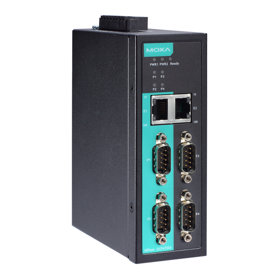
3. Hardware Introduction
Each model in the NPort IA5450A Series has four RS-232/422/485
3-in-1 DB9 serial ports for serial data communication, which are
located on the front of the unit, and there is an 8-contact
screw-type terminal block located on the top for power input and
relay output.
P/N: 1802051500311
– 1 –
NPort IA5450A Series Appearance
Top View
Front View
Side View
PWR1 PWR2 Ready
P1
P2
P3
P4
10
10
E1
E2
100
100
P1
P3
P2
P4
NPort IA5450A
Ethernet switch ports
LED indicators
Reset to default button
RS-232/422/485 serial ports
Dual power inputs and
relay output
The Reset to Default Button—Depress the Reset to default
button for 5 continuous seconds to load the factory default settings:
Use a pointed object, such as a straightened paper clip or toothpick,
to depress the Reset to default button. This will cause the Ready
LED to blink on and off. The factory default settings are loaded
once the Ready LED stops blinking (after about 5 seconds). At this
point, you can release the Reset to default button.
NPort IA5450A Series LED Indicators (front panel)
Name
Color
Function
PWR1,
red
Power is being supplied to power input PWR1,
PWR2
PWR2.
Ready
red
Steady on: Power is on and the NPort IA5450A
series is booting up.
Blinking: Indicates an IP conflict, the DHCP or
BOOTP server did not respond properly, or a relay
output occurred.
green
Steady on: Power is on and the NPort IA5450A
series is functioning normally.
Blinking: The device server has been located by
Administrator's "Locate" function.
off
Power is off, or a power error condition exists.
E1, E2
orange 10 Mbps Ethernet connection.
green
100 Mbps Ethernet connection.
off
Ethernet cable is disconnected, or has a short.
P1, P2,
orange Serial port is receiving data.
P3, P4
green
Serial port is transmitting data.
off
No data is being transmitted or received through
the serial port.
– 2 –
4. Hardware Installation Procedure
STEP 1: After removing the NPort IA5450A series from the box,
the first thing you should do is connect the power
adaptor. Connect the 12-48 VDC power line with the
NPort IA5450A series' terminal block, or connect the
DIN-Rail power supply with the NPort IA5450A series'
terminal block.
STEP 2: Connect the NPort IA5450A series to a network. Use a
standard straight-through Ethernet cable to connect to a
Hub or Switch. When setting up or testing the NPort
IA5450A series, you might find it convenient to connect
directly to your computer's Ethernet port. In this case,
use a cross-over Ethernet cable.
STEP 3: Connect the NPort IA5450A series' serial port to a serial
device.
DIN-Rail
STEP 4: The NPort IA5450A series is designed to be attached to a
DIN-Rail or mounted on a wall. For DIN-Rail mounting,
push down the spring and properly attach it to the
DIN-Rail until it "snaps" into place. For wall mounting,
install the wall mount kit (optional) first, and then screw
the device onto the wall. The following figure illustrates
the two mounting options:
Wall Mount
Step1: Install Wall mount kit
Step2: Screw onto wall
5. Software Installation Information
To install NPort Administration Suite, insert the Document &
Software CD into your computer's CD-ROM drive. Once the
installation window opens, click on the Installation
Administration Suite button, and then follow the instructions on
the screen. To view detailed information about NPort
Administration Suite, click on the Documents button, and then
select NPort IA5450A series User's Manual to open the pdf version
of this user's manual.
DIN-Rail
Step1: Push down the spring
Step2: Click into DIN rail
– 3 –
Advertisement
Table of Contents

Related Manuals for Moxa Technologies NPort IA5450A


Summary of Contents for Moxa Technologies NPort IA5450A
-
Page 1: Hardware Installation Procedure
RS-232/422/485 Reset to default button RS-232/422/485 serial ports STEP 4: The NPort IA5450A series is designed to be attached to a Dual power inputs and serial devices, such as PLCs, sensors, meters, motors, drives, relay output DIN-Rail or mounted on a wall. -
Page 2: Specifications
Four cables are available as optional accessories that can be used Operating Temperature: to connect the NPort IA5450A series to RS-232 serial devices. For Standard models: 0 to 60°C (32 to 140°F) your convenience, we show precise cable wiring diagrams for each of the two cables.
Need help?
Do you have a question about the NPort IA5450A and is the answer not in the manual?
Questions and answers