Moxa Technologies ioLogik E1210 User Manual
Hide thumbs
Also See for ioLogik E1210:
- User manual (117 pages) ,
- Manual (7 pages) ,
- Quick installation manual (2 pages)

Related Manuals for Moxa Technologies ioLogik E1210


Summary of Contents for Moxa Technologies ioLogik E1210
- Page 1 ioLogik E1200 Series User’s Manual Second Edition, April 2010 www.moxa.com/product © 2010 Moxa Inc. All rights reserved. Reproduction without permission is prohibited.
-
Page 2: Copyright Notice
ioLogik E1200 series User’s Manual The software described in this manual is furnished under a license agreement, and may be used only in accordance with the terms of that agreement. Copyright Notice Copyright © 2010 Moxa Inc. All rights reserved. Reproduction without permission is prohibited. -
Page 3: Table Of Contents
Table of Contents Chapter 1. Introduction ....................1-1 Overview ..........................1-2 Star Topology of Ethernet Automation ................ 1-2 Daisy-chain Ethernet I/O Connection................1-3 Efficient Ethernet Device Connectivity ................ 1-3 Product Model Information ....................1-4 Product Features ........................1-4 Package List ......................... 1-4 Product Specifications ...................... - Page 4 Chapter 4. Using ioSearch ..................4-1 Introduction to ioSearch ....................... 4-2 ioSearch Main Screen......................4-2 Main Screen Overview ....................4-2 Main Items..........................4-3 System .......................... 4-3 Sort ..........................4-4 Quick Links ........................4-4 Main Function ........................4-5 Locate ........................... 4-5 Firmware Upgrade......................4-5 Unlock ..........................
- Page 5 Appendix D. Pinouts ...................... D-2 Pin Assignment of Terminal Blocks ..................D-2 Appendix E. Federal Communication Commission Interference Statement .... E-1 Appendix F. European Community (CE)...............F-1...
-
Page 6: Chapter 1. Introduction
Introduction Chapter 1. The ioLogik E1200 series is a stand-alone remote Ethernet I/O server that can connect sensors and on/off switches for automation applications over Ethernet and IP-based networks. The following topics are covered in this chapter: Overview Star Topology of Ethernet Automation Daisy-chain Ethernet I/O Connection Efficient Ethernet Device Connectivity Product Model Information... -
Page 7: Overview
ioLogik E1200 Series User’s Manual Introduction Overview The ioLogik E1200 series is a stand-alone, remote Ethernet I/O which has two embedded switch ports. They are designed for remote data acquisition and monitoring of attached sensors, transmitters, transducers, and valves over a network. Star Topology of Ethernet Automation Ethernet requires infrastructure equipment such as switches for connecting a variety of different devices to the network. -
Page 8: Daisy-Chain Ethernet I/O Connection
ioLogik E1200 Series User’s Manual Introduction Daisy-chain Ethernet I/O Connection The ioLogik E1200 industrial remote Ethernet I/O has two embedded Ethernet switch ports that allow information to flow to another local Ethernet device or connect to the next ioLogik in the daisy-chain. -
Page 9: Product Model Information
E1200 Series User’s Manual Introduction Product Model Information Model Description ioLogik E1210 Remote Ethernet I/O with 2-port Ethernet switch and 16 DIs Remote Ethernet I/O with 2-port Ethernet switch and 16 DOs ioLogik E1211 ioLogik E1212 Remote Ethernet I/O with 2-port Ethernet switch, 8 DIs, and 8 DIOs... -
Page 10: Product Specifications
ioLogik E1200 Series User’s Manual Introduction Product Specifications Ethernet 2 x 10/100 Mbps switch ports, RJ45 Protection 1.5 KV magnetic isolation Protocols Modbus/TCP, OPC Server, TCP/IP, UDP, DHCP, Bootp, HTTP Analog Input Type Differential input 16 bits Resolution 12 samples per second (all channels) Sampling Rate I/O Mode Voltage or Current... - Page 11 ioLogik E1200 Series User’s Manual Introduction Wet Contact Logic 0: 0 to 3 VDC; Logic 1: 10 to 30 VDC (DI COM to DI) Isolation 3K VDC or 2K Vrms Counter/Frequency 250 Hz, power off storage Digital Output I/O Mode DO or Pulse Output (up to 500 Hz) Pulse Wave Width/Frequency 1 ms/500 Hz Over-voltage Protection...
-
Page 12: Physical Dimensions
ioLogik E1200 Series User’s Manual Introduction IEC 61000-4-3 (RS), Level 2 IEC 61000-4-4 (EFT), Level 2 IEC 61000-4-5 (Surge), Level 3 IEC 61000-4-6 (CS), Level 2 IEC 61000-4-8 (PM), Level 1 IEC 61000-4-11 (DIP) IEC 61000-6-2 IEC 61000-6-4 (EMC) Safety UL508 Warranty 2 years... -
Page 13: Led Indicators
ioLogik E1200 Series User’s Manual Introduction NOTE: The reset button restarts the server and resets all settings to factory defaults. Use a pointed object such as a straightened paper clip to hold in the reset button for 5 sec. The factory defaults will be loaded once the Ready LED turns green again. -
Page 14: Chapter 2. Initial Setup
Initial Setup Chapter 2. This chapter describes how to install the ioLogik E1200. The following topics are covered: Hardware Installation Connecting the Power Grounding the ioLogik E1200 Connecting to the Network Jumper Settings I/O Wiring Diagrams Software Installation Load Factory Default... -
Page 15: Hardware Installation
ioLogik E1200 User’s Manual Initial Setup Hardware Installation Connecting the Power Connect the 12 to 36 VDC power line to the ioLogik E1200’s terminal block on the top panel. If power is properly supplied, the Power LED will glow a solid amber color. ATTENTION Disconnect the power before installing or wiring Disconnect the power cord before installing or wiring your ioLogik E1200. -
Page 16: Jumper Settings
ioLogik E1200 User’s Manual Initial Setup Jumper Settings The ioLogik E1212, E1240, and E1242 require configuring the jumpers inside the enclosure. Remove the screw on the back panel and open the cover to configure the jumpers. DIO mode configuration is as follows (default is DO Mode) Analog mode configuration is as follows (default is Voltage Mode) ATTENTION Remove the screw on the back panel and open the cover to configure the jumpers. - Page 17 ioLogik E1200 User’s Manual Initial Setup...
-
Page 18: Software Installation
ioLogik E1200 User’s Manual Initial Setup Software Installation ioSearch is a search utility that helps the user locate an ioLogik E1200 on the local network. Find the ioSearch utility in the Document and Software CD under Software ioSearch, or download the latest version from Moxa’s website. -
Page 19: Chapter 3. Using The Web Console
Using the Web Console Chapter 3. The ioLogik E1200’s main configuration and management utility is the built-in web console, which can be used to configure a wide range of options. The following topics are covered: Introduction to the Web Console Overview Network Settings General Settings... -
Page 20: Introduction To The Web Console
ioLogik E1200 User’s Manual Using the Web Console Introduction to the Web Console The ioLogik E1200 web console is a browser-based configuration utility. When the ioLogik E1200 is connected to your network, you may enter the server’s IP address in your web browser to access the web console. -
Page 21: Overview
ioLogik E1200 User’s Manual Using the Web Console Overview The Overview page contains basic information about the ioLogik E1200, including the model name, serial number, firmware version, MAC address, and current IP address. Most importantly, you can see the current I/O status by hitting the F5 key on the computer keyboard to refresh the page. Network Settings General Settings On the General Settings page, you can assign a server name and location to assist you in... -
Page 22: Ethernet Configuration
ioLogik E1200 User’s Manual Using the Web Console Ethernet Configuration On the Ethernet Configuration page, you can set up a static or dynamic IP address for the ioLogik E1200, and configure the subnet mask and gateway address. User-defined Modbus Addressing To control an input or output channel of a remote Ethernet I/O device running the most general Modbus/TCP protocol requires specifying the Modbus address of those input and output channels. -
Page 23: Default Address
ioLogik E1200 User’s Manual Using the Web Console User-defined Modbus Addressing The input and output address can be configured in a different format on a specific settings page. Check the “Enable User-defined Modbus Addressing” box, select the Modbus function, and then configure the start address of each item. -
Page 24: I/O Settings
ioLogik E1200 User’s Manual Using the Web Console I/O Settings DI Channels The status of each DI (digital input) channel appears on the DI Channels page. You can also configure each channel’s digital input mode and parameters by clicking on the channel. DI channels can operate in DI mode or Event Counter mode. -
Page 25: Do Channels
ioLogik E1200 User’s Manual Using the Web Console DO Channels On the DO Channels page, configure each DO (digital output) channel by clicking on the channel. DO Channels can operate in DO mode or Pulse Output mode. In DO mode, output is either on or off. In Pulse Output mode, a configurable square wave is generated. -
Page 26: Ai Channels
ioLogik E1200 User’s Manual Using the Web Console AI Channels The current status of each AI (analog input) channel can be viewed on the AI Channels page. Click on a specific channel to enable or disable the AI channel by checking the “Enable AI Channel”... -
Page 27: Ao Channels
ioLogik E1200 User’s Manual Using the Web Console The Auto scaling function maps the original AI value linearly to a scaled value. Note that the scaled value’s Modbus address differs from the original value. The slope-intercept function is used to compensate when the measurement requires a slight adjustment. - Page 28 ioLogik E1200 User’s Manual Using the Web Console The Auto scaling function maps the original AO output linearly to a scaled value. Note that the scaled value’s Modbus address differs from the original value. 3-10...
-
Page 29: Rtd Channels
ioLogik E1200 User’s Manual Using the Web Console RTD Channels The current status of each RTD (Resistance Temperature Detector) channel can be viewed on the RTD Channel page. Click on a specific channel to access the RTD channel settings. Select the “Enable RTD Channel” box and then select the sensor type that meets the physical attachment to the ioLogik E1200. -
Page 30: Tc Channels
ioLogik E1200 User’s Manual Using the Web Console The ioLogik E1200 allows you to manually adjust the current temperature reading. In each channel configuration section, select the channel, apply the offset value, and click the “Submit” button to perform the task. TC Channels The current status of each TC (Thermocouple) channel can be viewed on the TC Channel page. - Page 31 ioLogik E1200 User’s Manual Using the Web Console The ioLogik E1200 allows you to calibrate the temperature sensors. In each channel configuration section, follow the instructions and click the “Calibrate” button to start the TC sensor calibration. Each calibration requires about 30 seconds (per channel). The ioLogik E1200 allows you to manually adjust the current temperature reading.
-
Page 32: System Management
ioLogik E1200 User’s Manual Using the Web Console System Management IP Accessibility You can control network access to the ioLogik E1200 from the IP Accessibility page by only allowing access from specific IP addresses. When the accessible IP list is enabled, a host’s IP address must be listed in order to gain access to the ioLogik E1200. -
Page 33: Network Connection
ioLogik E1200 User’s Manual Using the Web Console Network Connection TCP connections from other hosts appear on the Network Connection page. This information can assist you with managing your devices. Firmware Update Load new or updated firmware onto the ioLogik from the Firmware Update page. Import System Config Import a configuration into the ioLogik server from the Import System Config page. -
Page 34: Export System Config
ioLogik E1200 User’s Manual Using the Web Console Export System Config On the Export System Config page, you can save the ioLogik’s configuration into a file for backup or import into another ioLogik server. Change Password For all changes to the ioLogik E1200’s password protection settings, you will first need to enter the old password. -
Page 35: Save/Restart
ioLogik E1200 User’s Manual Using the Web Console Save/Restart If you change the configuration, do not forget to reboot the system. 3-17... -
Page 36: Chapter 4. Using Iosearch
Using ioSearch Chapter 4. In this chapter we cover ioSearch, which is used to search and locate ioLogik E1200 units. The following topics are covered: Introduction to ioSearch ioSearch Main Screen Main Screen Overview Main Items System Sort Quick Links Main Function Locate Firmware Upgrade... -
Page 37: Introduction To Iosearch
ioLogik E1200 User’s Manual Using ioSearch Introduction to ioSearch ioSearch is for locating or searching for an Logik E1200 on the physical network. The following functions are supported by the ioSearch utility. Search for and locate ioLogik E1200 units. IP address configuration. Firmware upgrade for multiple ioLogik E1200 units (same model). -
Page 38: Main Items
ioLogik E1200 User’s Manual Using ioSearch Main Items System Several operations are possible from the System menu. Auto Scan Active Ethernet I/O Servers will search for ioLogik servers on the network. When connecting for the first time or recovering from a network disconnection, you can use this command to find I/O servers that are on the network. -
Page 39: Sort
ioLogik E1200 User’s Manual Using ioSearch Sort The Sort menu allows the server list in the navigation panel to be sorted by ioLogik connection and server (model). Quick Links Quick links are provided to search for I/O servers on the network and sort the server list. Automatically search the local network Sort by ioLogik E1200’s IP address (connection) Sort by ioLogik E1200 model... -
Page 40: Main Function
ioLogik E1200 User’s Manual Using ioSearch Main Function Right click on a particular ioLogik E1200 to view the ioSearch function menu. Locate The locate function helps users find a dedicated ioLogik on the network. When this function is triggered, the ready LED on the selected unit will start to blink indicating its location. Firmware Upgrade The ioLogik E1200 supports a remote firmware upgrade function. -
Page 41: Unlock
ioLogik E1200 User’s Manual Using ioSearch Unlock If an ioLogik E1200 is password protected, unlock the ioLogik E1200 by entering the password before using any of the functions. Import Select this command to reload a configuration that was exported to a text file. Importing one configuration file to multiple ioLogik E1200 units (same model) is allowed. -
Page 42: Export
ioLogik E1200 User’s Manual Using ioSearch Export The export function is used to export the current configuration file of an ioLogik E1200. The export file format will be ik12xx.txt where “xx” represents the model type of the ioLogik E1200. Exporting multiple files for different models of ioLogik E1200 is allowed. The file format is ik12xx_MAC Address.txt, where the xx represents the model types of the ioLogik E1200. -
Page 43: Restart System
ioLogik E1200 User’s Manual Using ioSearch Restart System Select this command to restart the selected ioLogik E1200. Restarting multiple ioLogik E1200 units is allowed. Select the ioLogik E1200 and right click to process this function. Reset to Default Select this function to reset all settings, including console password, to factory default values. Resetting multiple ioLogik E1200 units to the default configuration is allowed. -
Page 44: Chapter 5. Active Opc Server Lite
Active OPC Server Lite Chapter 5. In this chapter, we explain how to use the web console of the ioLogik E1200 to connect to the Active OPC Server Lite package. The following topics are covered in this chapter: OLE for Process Control Introduction to Active OPC Server Lite Active OPC Server Lite—From Pull to Push Features of Active OPC Server Lite... -
Page 45: Ole For Process Control
ioLogik E1200 User’s Manual Active OPC Server Lite OLE for Process Control OPC (originally OLE for process control) is an industry standard created with the collaboration of a number of leading worldwide automation hardware and software suppliers working in cooperation with Microsoft. The standard defines methods for exchanging real-time automation data between PC-based clients using Microsoft operating systems. -
Page 46: Active Opc Server Lite-From Pull To Push
ioLogik E1200 User’s Manual Active OPC Server Lite Active OPC Server Lite—From Pull to Push When first looking up the I/O devices’ Modbus table, creating one tag requires 19 or more steps, including specifying the IP address, selection of the protocols, and definition of the data type. The procedure is repeated over and over until all the devices and tags have been created. -
Page 47: Features Of Active Opc Server Lite
ioLogik E1200 User’s Manual Active OPC Server Lite The “push” technology also supports tag updates. When the I/O the status changes, updates will be sent from the ioLogik to Active OPC Server Lite. Compared with constantly polling (pull-based) the status, this feature efficiently reduces network bandwidth usage and speeds up the response time with event-driven, push-based status updates. -
Page 48: Active Opc Server Lite Specifications
1.0a, 2.0, 2.05a, 3.0 Max. tags 1,200 (V1.7 or later) ioLogik Support Product Models ioLogik E1210, E1211, E1212, E1214, E1240, E1241, E1242, E1260, E1262 ioLogik E2210, E2212, E2214, E2240, E2242, E2242-T, E2260, E2262 ioLogik E4200 ioLogik W5340, W5340-T, W5312, W5312-T... -
Page 49: Active Opc Server Lite
ioLogik E1200 User’s Manual Active OPC Server Lite Active OPC Server Lite Main Screen Overview Active OPC Server Lite’s main screen displays a figure of the mapped ioLogik with the status of every I/O tag. Note that configuration and tags are not available until the ioLogik creates the tags. Active OPC Server Lite Main Screen 1. -
Page 50: Menu Items
ioLogik E1200 User’s Manual Active OPC Server Lite Menu Items File From the File menu, you can export the list ioLogik units that are currently displayed in the navigation panel. You also can import a list into Active OPC Server Lite. The file will have the .mdb extension, and can be opened using Microsoft Office Access. -
Page 51: Sort
ioLogik E1200 User’s Manual Active OPC Server Lite Stop Listen allows users to stop receiving tag generation messages and I/O status updates. Output Control Timeout allows users to define the timeout interval of a controlling output channel on a remote ioLogik. Register OPC Server is used to register the DCOM components to the Windows system. -
Page 52: Tag Generation
ioLogik E1200 User’s Manual Active OPC Server Lite Tag Generation Tag configuration of an ioLogik E1200 is specified by its web console. Open the browser and go to the Active OPC Server Settings page. Follow these steps to create the tag from the ioLogik E1200 to Active OPC Server Lite: 1. -
Page 53: Heartbeat Interval
ioLogik E1200 User’s Manual Active OPC Server Lite 2. On the Create AOPC Tag page, click on the Create Tags button to push the tag configuration to Active OPC Server Lite. 3. Launch the Active OPC Server Lite program; tags will be automatically created. 4. -
Page 54: Read/Write Privilege
ioLogik E1200 User’s Manual Active OPC Server Lite Read/Write Privilege An input channel can only be read while an output channel shows “read/write acceptable” on the Active OPC Server Lite. OPC Test Client An OPC client software is embedded in the Active OPC Server Lite package for test purposes. After configuring the tags on the Active OPC Server Lite, this ClientTest can be launched from the Windows Start menu: Start Program Files... - Page 55 ioLogik E1200 User’s Manual Active OPC Server Lite Click on Group Add and specify the Group Name (user-defined). A blank tag monitoring screen will open. Click Item Browse and select the channel that needs to be monitored. 5-12...
- Page 56 ioLogik E1200 User’s Manual Active OPC Server Lite To write to the output channel, specify an output channel, and then select Item Write from the menu bar. 5-13...
-
Page 57: Appendix A. Modbus/Tcp Default Address Mappings
Modbus/TCP Default Address Mappings Appendix A. E1210 Modbus Mapping 0xxxx Read/Write Coils (Functions 1, 5, 15) Reference Address Data Type Description 00257 0x0100 1 bit CH0 DI Counter Operate Status 0: Stop 1: Start(R/W) 00258 0x0101 1 bit CH1 DI Counter Operate Status 0: Stop 1: Start(R/W) 00259 0x0102 1 bit... - Page 58 ioLogik E1200 User’s Manual Modbus/TCP Address Mappings 0 : Return illegal data value(0x03) 00278 0x0115 1 bit CH5 DI Clear Count Value Read Always return:0 Write: 1 : Clear counter value 0 : Return illegal data value(0x03) 00279 0x0116 1 bit CH6 DI Clear Count Value Read Always return:0...
- Page 59 ioLogik E1200 User’s Manual Modbus/TCP Address Mappings 1xxxx Read Only Coils (Function 2) Reference Address Data Type Description 10001 0x0000 1 bit CH0 DI Value,0=OFF,1=ON (Read only) 10002 0x0001 1 bit CH1 DI Value,0=OFF,1=ON (Read only) 10003 0x0002 1 bit CH2 DI Value,0=OFF,1=ON (Read only) 10004 0x0003...
-
Page 60: E1211 Modbus Mapping
ioLogik E1200 User’s Manual Modbus/TCP Address Mappings 30042 0x0029 1 word CH12 DI Counter Value Lo- Word (Read only) 30043 0x002A 1 word CH13 DI Counter Value Hi- Word (Read only) 30044 0x002B 1 word CH13 DI Counter Value Lo- Word (Read only) 30045 0x002C 1 word... -
Page 61: E1212 Modbus Mapping
ioLogik E1200 User’s Manual Modbus/TCP Address Mappings E1212 Modbus Mapping 0xxxx Read/Write Coils (Functions 1, 5, 15) Reference Address Data Type Description DO Channel 00001 0x0000 1 bit CH0 DO Value 0: Off 1: On 00002 0x0001 1 bit CH1 DO Value 0: Off 1: On 00003 0x0002 1 bit... - Page 62 ioLogik E1200 User’s Manual Modbus/TCP Address Mappings 0 : Return illegal data value(0x03) 00276 0x0113 1 bit CH3 DI Clear Count Value Read Always return:0 Write: 1 : Clear counter value 0 : Return illegal data value(0x03) 00277 0x0114 1 bit CH4 DI Clear Count Value Read Always return:0...
- Page 63 ioLogik E1200 User’s Manual Modbus/TCP Address Mappings Write: 1 : Clear counter value 0 : Return illegal data value(0x03) 1xxxx Read Only Coils (Function 2) Reference Address Data Type Description 10001 0x0000 1 bit CH0 DI Value,0=OFF,1=ON (Read only) 10002 0x0001 1 bit CH1 DI Value,0=OFF,1=ON (Read only)
-
Page 64: E1214 Modbus Mapping
ioLogik E1200 User’s Manual Modbus/TCP Address Mappings 30037 0x0024 1 word CH10 DI Counter Value Hi- Word (Read only) 30038 0x0025 1 word CH10 DI Counter Value Lo- Word (Read only) 30039 0x0026 1 word CH11 DI Counter Value Hi- Word (Read only) 30040 0x0027 1 word... - Page 65 ioLogik E1200 User’s Manual Modbus/TCP Address Mappings 00262 0x0105 1 bit CH5 DI Counter Operate Status 0: Stop 1: Start(R/W) 00273 0x0110 1 bit CH0 DI Clear Count Value Read Always return:0 Write: 1 : Clear counter value 0 : Return illegal data value(0x03) 00274 0x0111 1 bit...
-
Page 66: E1240 Modbus Mapping
ioLogik E1200 User’s Manual Modbus/TCP Address Mappings 30022 0x0015 1 word CH2 DI Counter Value Lo- Word (Read only) 30023 0x0016 1 word CH3 DI Counter Value Hi- Word (Read only) 30024 0x0017 1 word CH3 DI Counter Value Lo- Word (Read only) 30025 0x0018 1 word... -
Page 67: E1241 Modbus Mapping
ioLogik E1200 User’s Manual Modbus/TCP Address Mappings 30023 0x0016 1 word CH7 Read AI Scaling Value Hi (float) 30024 0x0017 1 word CH7 Read AI Scaling Value Low (float) E1241 Modbus Mapping 3xxxx Read Only Registers (Function 4) Reference Address Data Type Description 30001 0x0000... - Page 68 ioLogik E1200 User’s Manual Modbus/TCP Address Mappings 00275 0x0112 1 bit CH2 DI Clear Count Value Read Always return:0 Write: 1 : Clear counter value 0 : Return illegal data value(0x03) 00276 0x0113 1 bit CH3 DI Clear Count Value Read Always return:0 Write:...
-
Page 69: E1260 Modbus Mapping
ioLogik E1200 User’s Manual Modbus/TCP Address Mappings 30023 0x0016 1 word CH3 DI Counter Value Hi- Word (Read only) 30024 0x0017 1 word CH3 DI Counter Value Lo- Word (Read only) 30025 0x0018 1 word CH4 DI Counter Value Hi- Word (Read only) 30026 0x0019 1 word... -
Page 70: E1262 Modbus Mapping
ioLogik E1200 User’s Manual Modbus/TCP Address Mappings E1262 Modbus Mapping 3xxxx Read Only Registers (Function 4) Reference Address Data Type Description 32049 0x0800 1 word CH0 TC Minimum Value Hi Word Unit:0.1 (Celsius, Fahrenheit) 0.0001(mV) 32050 0x0801 1 word CH0 TC Minimum Value Lo Word Hi+Lo Range: 0~4294967295 Unit:0.1 (Celsius, Fahrenheit) 0.0001(mV) 32051... -
Page 71: Appendix B. Used Network Port Numbers
Used Network Port Numbers Appendix B. ioLogik E1200 Network Port Usage Port Type Usage Web console service Modbus/TCP communication BOOTP/DHCP 4800 Auto search Export/import configuration file 9900 Active OPC Server Lite 9950 Active OPC Server Lite... -
Page 72: Appendix C. Factory Defaults
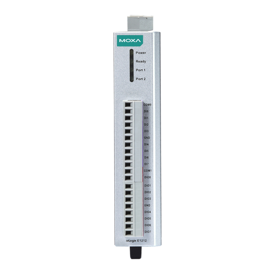
Factory Defaults Appendix C. The ioLogik E1200 series products are configured with the following factory defaults: Default IP address: 192.168.127.254 Default Netmask: 255.255.255.0 Default Gateway: 0.0.0.0 Communication watchdog: Disable Modbus/TCP Alive Check: Modbus/TCP Timeout Interval: 60 sec DI Mode: Filter time: 100 ms Trigger for counter: Lo to Hi... - Page 73 E2210 User’s Manual Pinouts and Cable Wiring Pinouts Appendix D. Pin Assignment of Terminal Blocks ioLogik E1210 ioLogik E1211 ioLogik E1212 ioLogik E1214 ioLogik E1240 (top to bottom) (top to bottom) (top to bottom) (top to bottom) (top to bottom)
- Page 74 Federal Communication Commission Appendix E. Interference Statement FCC Warning! This equipment has been tested and found to comply with the limits for a Class A digital device, pursuant to part 15 of the FCC Rules. Operation is subject to the following two conditions: (1) This device may not cause harmful interference, and (2) this device must accept any interference received, including interference that may cause undesired operation.
- Page 75 European Community (CE) Appendix F. This is a Class A product. In a domestic environment, this product may cause radio interference in which case the user may be required to take adequate measures.
Need help?
Do you have a question about the ioLogik E1210 and is the answer not in the manual?
Questions and answers