Table of Contents
Advertisement
Quick Links
Advertisement
Table of Contents

Subscribe to Our Youtube Channel
Related Manuals for Moxa Technologies ioLogik R2110 Series


Summary of Contents for Moxa Technologies ioLogik R2110 Series
- Page 1 R2110 Series User’s Manual RS-485 Remote I/O Server with 12 DI, 8 DO First Edition, July 2006 www.moxa.com/product MOXA Technologies Co., Ltd. Tel: +886-2-8919-1230 Fax: +886-2-8919-1231 Web: www.moxa.com MOXA Technical Support Worldwide: support@moxa.com...
- Page 2 The software described in this manual is furnished under a license agreement, and may be used only in accordance with the terms of that agreement. Copyright Notice Copyright © 2006 MOXA Technologies Co., Ltd. All rights reserved. Reproduction without permission is prohibited.
-
Page 3: Table Of Contents
Table of Contents Chapter 1 Introduction ....................1-1 Overview ..........................1-2 Features of the ioLogik R2110 RS-485 Remote I/O Server ..........1-2 Package Checklist......................... 1-3 Product Specifications ......................1-3 All ioLogik R2000 Series Remote I/O Servers............. 1-3 Specific to the ioLogik R2110 ..................1-4 Pin Assignment........................ - Page 4 Function 8........................A-8 Appendix B Factory Default Settings ................B-1 Appendix C Port Pinout Diagrams................C-1 Serial Port Pinouts ........................C-1 Appendix D Service Information.................. D-1 MOXA Internet Services ..................... D-2 Problem Report Form ......................D-3 Product Return Procedure....................D-4...
-
Page 5: Chapter 1 Introduction
Introduction Chapter 1 The ioLogik R2110 is an Easy View, stand-alone, remote digital I/O server that can be used to connect sensors and on/off switches over an RS-485 connection for use in automation applications. The following topics are covered in this chapter: Overview Features of the ioLogik R2110 RS-485 Remote I/O Server Package Checklist... -
Page 6: Overview
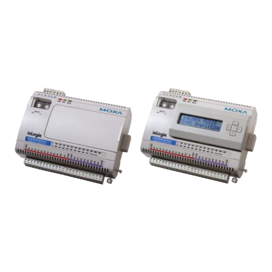
R2110 Series User’s Manual Introduction Overview Without LCD Display Module With LCD Display Module The ioLogik R2110 is part of the R2000 series of ioLogik Remote I/O servers, which are designed to link sensors, transmitters, transducers, and valves to an RS-485 network. The ioLogik R2110 is differentiated from other R2000 series models by its digital I/O and its Easy View function. -
Page 7: Package Checklist
R2110 Series User’s Manual Introduction Package Checklist The ioLogik R2110 is shipped with the following items: Standard Accessories ioLogik R2110 RS-485 I/O Server × 1 Software CD with documentation × 1 Optional Accessories LDP1602 ioLogik LCD display module (16 × 2 text screen and 5 push-buttons) NOTE: Notify your sales representative if any of these items are missing or damaged. -
Page 8: Specific To The Iologik R2110
R2110 Series User’s Manual Introduction Ground Connection DIN-rail, and panel mount holes equipped ground connection Terminal Block Removable terminal block (3.81 mm) (DI/O) Signal indication LEDs for each channel (DI/O) Regulatory approval Shock, free fall, vibration CE Class A, Level 3, Criteria B... -
Page 9: Pin Assignment
R2110 Series User’s Manual Introduction Pin Assignment Terminal Blocks UNIT ID R2110 RS-485 Signals Signals V+ (12 to 48 VDC) Data+ Data- Signals DI.COM DI 0 DI 1 DI 2 DI 3 DI 4 DI 5 DI 6 Signals... -
Page 10: Chapter 2 Hardware Installation
Hardware Installation Chapter 2 In this chapter, we describe the hardware installation procedure for the ioLogik R2110 remote I/O server. The following topics are covered in this chapter. Connecting the Hardware Connecting the Power Grounding the ioLogik R2110 Connecting to I/O Device Servers LED Indicators Factory Default Settings ioAdmin... -
Page 11: Connecting The Hardware
R2110 Series User’s Manual Hardware Installation Connecting the Hardware Connecting the Power Connect the 12 to 48 VDC power line with the ioLogik R2110’s terminal block. If the power is properly supplied, the power LED will glow a solid red color until the system is ready Grounding the ioLogik R2110 The ioLogik R2110 is equipped with two protection ground points. -
Page 12: Led Indicators
R2110 Series User’s Manual Hardware Installation 3. DO sink type * DO PWR is for powering up the field power LED LED Indicators Description System LEDs The power is on. There is a system error. Green The ioLogik is functioning normally. -
Page 13: Lcd Display Module
R2110 Series User’s Manual Hardware Installation LCD Display Module As an Easy View device, the ioLogik R2110 supports an optional detachable LCD display module for easier field maintenance. The display module is hot-pluggable and can be used to both display and modify the server settings. -
Page 14: Configuring The Iologik R2110 With Ioadmin
Configuring the ioLogik R2110 Chapter 3 with ioAdmin This chapter covers the following topics explains how to configure the I/O channels. Overview Installing ioAdmin Searching for the ioLogik R2110 Monitoring I/O Status On-line Wiring Guide Modbus/RTU Server Information Logging In Configuring Digital Input/Output Channels Testing DI/O Channels Configuring Digital Input Channels... -
Page 15: Overview
R2110 Series User’s Manual Configuring with ioAdmin Overview ioAdmin is a monitoring and configuration utility designed for use with ioLogik R2000 series I/O servers. It supports Windows 2000 and Windows XP and consists of the following software. ioAdmin ioLogik R2110 Wiring Guide... -
Page 16: Searching For The Iologik R2110
R2110 Series User’s Manual Configuring with ioAdmin Searching for the ioLogik R2110 From the pull-down menu, choose System Auto Scan Remote I/O Server. A system dialog window will pop up Make sure that RS-232/485 I/O server is selected and click on Port Settings to set/verify the... - Page 17 R2110 Series User’s Manual Configuring with ioAdmin When you click on Start Search, ioAdmin will begin searching up to 99 ports for your ioLogik R2110. The timeout interval is for RS-485 communication and defaults to 2000 ms. As soon as your ioLogik R2110 appears as shown below, you may click Stop.
-
Page 18: Monitoring I/O Status
R2110 Series User’s Manual Configuring with ioAdmin ATTENTION If ioAdmin is unable to find your ioLogik R2110, make sure that the baudrates match. See Chapter 2 for setting or viewing the baudrate on your ioLogik R2110. ATTENTION Even if ioAdmin is unable to find your ioLogik R2110, you may still access the On-line Wiring Guide. -
Page 19: On-Line Wiring Guide
R2110 Series User’s Manual Configuring with ioAdmin On-line Wiring Guide To access the On-line Wiring Guide, right click on the ioLogik R2110 graphic, then left click on Wiring Guide. This displays a help file showing the wiring information and electrical... -
Page 20: Modbus/Rtu
R2110 Series User’s Manual Configuring with ioAdmin If ioAdmin was unable to find your ioLogik R2110, you may still access the On-line Wiring Guide through the Help menu on the menu bar. Modbus/RTU The RS-485 port runs Modbus/RTU that can connect to any Modbus devices. You may use different methods to connect different combinations of ioLogik R2000 servers, I/O devices, and other servers. -
Page 21: Server Information
R2110 Series User’s Manual Configuring with ioAdmin Server Information The Server Information tab provides the Modbus addresses for all system configurations. This helps you verify the access authority of each address. The screen also displays a clear explanation of each item. -
Page 22: Testing Di/O Channels
R2110 Series User’s Manual Configuring with ioAdmin Testing DI/O Channels You may test each DI/O channel with ioAdmin. The settings are as follows: DI-DI: depends on the device DI-Counter: activate or stop event counting DO-DO: change status of the DO to ON or OFF... -
Page 23: Configuring Digital Input Channels
R2110 Series User’s Manual Configuring with ioAdmin Configuring Digital Input Channels The ioLogik R2110 is equipped with 12 digital inputs that can be set individually to DI or Event Counter mode. In DI mode, the specification is as follows:... - Page 24 R2110 Series User’s Manual Configuring with ioAdmin In Event Counter mode, the ioLogik R2110’s DI can connect to the limit switch or the proximity switch and can count the time based on the ON/OFF status. You can set the trigger for two modes, Lo to Hi, or Hi to Lo.
-
Page 25: Configuring Digital Output Channels
R2110 Series User’s Manual Configuring with ioAdmin Configuring Digital Output Channels The ioLogik R2110 is equipped with 8 digital output (sink) channels that can be set individually to DO or Pulse Output mode. In DO mode, the specification is Logic 0 (OFF)=open; Logic 1... -
Page 26: About Power On Settings
R2110 Series User’s Manual Configuring with ioAdmin In Pulse Output mode, the selected digital output channel will generate a square wave as specified in the pulse mode parameters. The Low and High parameters are in multiples of 10.0 ms, so a... -
Page 27: Host Connection Watchdog
R2110 Series User’s Manual Configuring with ioAdmin Safe Status is controlled by the ioLogik R2110’s Host Connection Watchdog and is activated after a break in RS-485 communication for a specified time interval. When the ioLogik R2110 enters Safe Status (i.e. after the break in RS-485 communication), your DI/O channel will respond as configured in its Safe Status settings. -
Page 28: Restarting The System
R2110 Series User’s Manual Configuring with ioAdmin Restarting the System You may use the Restart System command to restart the ioLogik R2110 from a remote site. Restoring Default Settings You may use ioAdmin to reset the system to factory defaults. -
Page 29: Exporting Iologik R2110 Settings
R2110 Series User’s Manual Configuring with ioAdmin Exporting ioLogik R2110 Settings ioLogik R2110 settings can be exported to a text file for backup. ioLogik 2000 RS-485 I/O Server Configuration ============================================ Date: 2006/6/25 Time: 下午 11:21:33 1. Model -------- IOLOGIK R2110 - RS-485 Remote I/O Server (12DI + 8DO) 2. -
Page 30: Password Protection
R2110 Series User’s Manual Configuring with ioAdmin 3. Modbus address table ----------------------- Channel No. I/O type Modbus reference Modbus address (Dec, Hex) DI00 Input 10001 0000, 0x0000 DI01 Input 10002 0001, 0x0001 DI02 Input 10003 0002, 0x0002 DI03 Input... - Page 31 R2110 Series User’s Manual Configuring with ioAdmin Firmware Upgrade Screens 3-18...
-
Page 32: Appendix A Modbus/Rtu Address Mappings
Modbus/RTU Address Mappings Appendix A ioLogik R2110 Modbus Mapping 0xxxx Read/Write Coils (Support Functions 1, 5, 15) Reference Address Data Type Description 00001 0x0000 1 bit CH0 DO Value 0: Off 1: On 00002 0x0001 1 bit CH1 DO Value 0: Off 1: On 00003 0x0002 1 bit... - Page 33 R2110 Series User’s Manual Modbus/RTU Address Mappings Reference Address Data Type Description 00035 0x0022 1 bit CH2 DO Power-On Pulse Operate Status 0: Off 1: On 00036 0x0023 1 bit CH3 DO Power-On Pulse Operate Status 0: Off 1: On...
- Page 34 R2110 Series User’s Manual Modbus/RTU Address Mappings Reference Address Data Type Description 00069 0x0044 1 bit CH8 DI Clear Counter Value read always: 0 Write: 1: Clear counter value 0: return Illegal Data Value 00070 0x0045 1 bit CH9 DI Clear Counter Value read always: 0...
- Page 35 R2110 Series User’s Manual Modbus/RTU Address Mappings Reference Address Data Type Description 00081 0x0050 1 bit CH8 DI Counter Overflow Status Read: 0: Normal 1: Overflow Write: 0: clear overflow status 1: return Illegal Data Value 00082 0x0051 1 bit...
-
Page 36: 1Xxxx Read-Only Coils (Support Function 2
R2110 Series User’s Manual Modbus/RTU Address Mappings Reference Address Data Type Description 00116 0x0073 1 bit CH7 DI Counter Safe Status 0: Off 1: On 00117 0x0074 1 bit CH8 DI Counter Safe Status 0: Off 1: On 00118... -
Page 37: 4Xxxx Read/Write Registers (Support Functions 3, 6, 16
R2110 Series User’s Manual Modbus/RTU Address Mappings 4xxxx Read/Write Registers (Support Functions 3, 6, 16) Reference Address Data Type Description 40001 0x0000 word CH0 DO Pulse Output Count Value Hi-Word 40002 0x0001 word CH0 DO Pulse Output Count Value Lo-Word... - Page 38 R2110 Series User’s Manual Modbus/RTU Address Mappings Reference Address Data Type Description 40041 0x0028 word CH0 DI / Counter Filter 40042 0x0029 word CH1 DI / Counter Filter 40043 0x002A word CH2 DI / Counter Filter 40044 0x002B word...
-
Page 39: Function 8
R2110 Series User’s Manual Modbus/RTU Address Mappings Function 8 Sub-function Data Field (Request) Data Field (Response) Description 0x0001 0x0000 Echo Request Data Reboot 0x0001 0xFF00 Echo Request Data Reset to Factory defaults... -
Page 40: Appendix B Factory Default Settings
Factory Default Settings Appendix B The ioLogik R2110 is configured with the following factory defaults: RS-485 Unit ID: Default baudrate: 115200 Kbps Communication watchdog: Disable DI Mode: 1 × 10 ms Filter time: Trigger for counter: Lo to Hi Counter status: Stop DO Mode: DO Safe Status:... -
Page 41: Appendix C Port Pinout Diagrams
Port Pinout Diagrams Appendix C Serial Port Pinouts ioLogik R2110 RS-485 Network Adapter Pin Assignment... -
Page 42: Appendix D Service Information
Service Information Appendix D This appendix contains information on how to contact MOXA for information about this and other MOXA products, as well as the procedure for reporting problems. In this appendix, we cover the following topics. MOXA Internet Services Problem Report Form Product Return Procedure... -
Page 43: Moxa Internet Services
R2110 Series User’s Manual Service Information MOXA Internet Services Customer satisfaction is our primary concern. To ensure that customers receive the full benefit of our products, MOXA Internet Services has been set up to provide technical support, driver updates, product information, and user’s manual updates. -
Page 44: Problem Report Form
R2110 Series User’s Manual Service Information Problem Report Form MOXA ioLogik R2110 RS-485 Remote I/O Server Customer name: Company: Tel: Fax: Email: Date: Product Model: ioLogik R2110 RS-485 Remote I/O Server Serial Number: _________________ Problem Description: Please describe the symptoms of the problem as clearly as possible, including any error messages you see. -
Page 45: Product Return Procedure
R2110 Series User’s Manual Service Information Product Return Procedure For product repair, exchange, or refund, please follow these instructions: Provide evidence of original purchase. Obtain a Product Return Agreement (PRA) from the sales representative or dealer. Fill out the Problem Report Form (PRF). Include as much detail as possible to expedite diagnosis of your product.
Need help?
Do you have a question about the ioLogik R2110 Series and is the answer not in the manual?
Questions and answers