Table of Contents
Advertisement
Quick Links
MiiNePort E1-SDK
Quick Installation Guide
First Edition, March 2012
Overview
The MiiNePort E1-SDK is a powerful and versatile software suite for
proprietary firmware development on the MiiNePort E1. To expedite
time-to-market, the MiiNePort E1-SDK provides comprehensive
tools for development, testing, and mass-production. The software
development kit includes:
•
MiiNePort-IDE - integrated platform for development of
serial-to-Ethernet firmware.
•
PComm Lite - software application for testing serial and
TCP/IP communication/transmission.
Search Utility - search-and-update firmware utility for
•
mass-production of modules and serial devices through
simultaneous multiple-unit configurations.
Available Starter Kits
•
MiiNePort E1-SDK: Software Development Kit for the
MiiNePort E1 Series
Package Checklist
Each MiiNePort package contains the following items:
•
1 MiiNePort E1-SDK module
•
1 MiiNePort E1-SDK evaluation board
•
1 MiiNePort E1-SDK Documentation and Software CD
•
1 universal power adaptor
•
2 power cords
•
1 null modem serial cable
•
1 cross-over Ethernet cable
•
1 USB cable
•
1 product warranty booklet
•
1 Quick Installation Guide (this guide)
Note: Please notify your sales representative if any of the above
items are missing or damaged.
P/N: 1802000012020
– 1 –
Hardware Installation Procedure
Follow these steps to prepare the module and evaluation board for
testing and application development.
ATTENTION
For detailed information about the pin assignments, wiring,
and board layouts, refer to Chapters 1 and 2 of the
MiiNePort E1/E2-SDK Series User's Manual
STEP1:
Connect the 12 to 48 VDC power line with the
evaluation board's power jack.
STEP 2:
Use an RJ45 Ethernet cable to connect the MiiNePort
E1 module to an Ethernet network.
STEP 3:
Use the USB cable to connect the evaluation board to
the PC.
Software Utility Installation Procedure
Use the following installation procedure for MiiNePort
E1-SDK software development kit (MiiNePort-IDE)
Software Installation
1. Start the MiiNePort-IDE setup program to begin the
installation. When the Welcome window opens, click on Next.
2. Click on Install to install program files in the default directory.
3. The Installing window reports the progress of the installation.
4. Click on Finish to complete the installation.
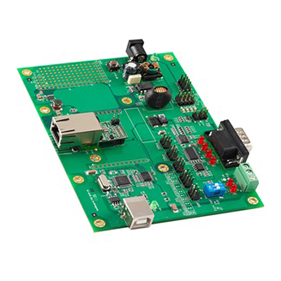
Evaluation Board Layout
– 2 –
Pin Assignment (MiiNePort E1 Series Modules)
Serial Signal Pins
Pin
Function
1
GND
2
VCC
3
Reset
4
Data Out
5
Data In
a
6
Ready/RTS
b
7
Reset to Default
c
8
CTS
a) Pin 6 can be configured as Ready/RTS (Request to Send),
Ready/DO, or RS-485 Tx Enabled (the default it Ready/RTS).
b) Pin 7 can be configured as Reset to Default, DIO, DTR, or RS-485
Tx Enabled (the default is Reset to Default).
c) Pin 8 can be configured as CTS (Clear to Send), DI, or DSR
(the default is CTS)
Ethernet Port Pins
RJ45
Pin
Signal
1
Tx+
2
3
Rx+
6
MiiNePort E1-SDK Evaluation Board
DB9 Male
Pin
RS232
1
DCD
2
RxD
3
TxD
4
DTR
5
GND
6
DSR
7
RTS
8
CTS
– 3 –
Tx-
Rx-
Advertisement
Table of Contents

Subscribe to Our Youtube Channel
Related Manuals for Moxa Technologies MiiNePort E1-SDK


Summary of Contents for Moxa Technologies MiiNePort E1-SDK
- Page 1 Chapters 1 and 2 of the MiiNePort E1/E2-SDK Series User’s Manual Overview Function The MiiNePort E1-SDK is a powerful and versatile software suite for STEP1: Connect the 12 to 48 VDC power line with the proprietary firmware development on the MiiNePort E1. To expedite evaluation board’s power jack.
- Page 2 Reference Material The following detailed user’s guides can be found on the Documentation and Software CD that came with your MiiNePort E1-SDK product. Certification This product complies with Chinese RoHS (Restriction of Hazardous Substances) regulations for Electronic Information Products. www.moxa.com/support The Americas: +1-714-528-6777 (toll-free: 1-888-669-2872) Europe: +49-89-3 70 03 99-0 Asia-Pacific: +886-2-8919-1230...
Need help?
Do you have a question about the MiiNePort E1-SDK and is the answer not in the manual?
Questions and answers