
Related Manuals for Siemens SIRIUS PROFINET


Summary of Contents for Siemens SIRIUS PROFINET
- Page 1 Industrial Controls SIRIUS PROFINET Communication Module for SIRIUS Soft Starter 3RW44 Gerätehandbuch Manual Edition 12/2013 Answers for industry.
- Page 3 ___________________ PROFINET Communication Module for Introduction SIRIUS Soft Starter 3RW44 ___________________ Safety information ___________________ Product description Industrial Controls ___________________ Installation / removal SIRIUS ___________________ Configuring/assigning PROFINET Communication Module parameters for SIRIUS Soft Starter 3RW44 ___________________ Commissioning Manual ___________________ Functions ___________________ Technical specifications ___________________ Dimension drawings...
- Page 4 Note the following: WARNING Siemens products may only be used for the applications described in the catalog and in the relevant technical documentation. If products and components from other manufacturers are used, these must be recommended or approved by Siemens. Proper transport, storage, installation, assembly, commissioning, operation and maintenance are required to ensure that the products operate safely and without any problems.
-
Page 5: Table Of Contents
Table of Contents Introduction........................... 9 Important notes ........................9 Safety information ........................13 Security information ........................ 13 Before commencing work: Isolating the equipment from the supply system and ensuring that it cannot be reconnected....................13 Data security in automation ....................14 Product description ........................ - Page 6 Table of Contents OPC UA server ........................47 7.2.1 Features of OPC UA .......................47 7.2.2 Reading and writing data ......................48 7.2.3 Activating the OPC UA server ....................48 7.2.4 Setting the IP parameters ......................49 7.2.5 Access to the OPC UA server ....................50 7.2.6 Establishing a connection to the OPC UA server ..............52 7.2.7...
- Page 7 Table of Contents A.1.13 Data record 95 - Read statistical data ..................95 A.1.14 Data record 96 - Read maximum pointer ................96 A.1.15 Data records 131, 141, 151 - Technology parameter 2: Read/write record 1, 2, 3....97 A.1.16 Data records 132, 142, 152 - Technology parameter 3: Read/write record 1, 2, 3....
- Page 8 Table of Contents PROFINET Communication Module for SIRIUS Soft Starter 3RW44 Manual, 12/2013, A5E31996495002A/RS-AA/001...
-
Page 9: Introduction
This manual is valid for the PROFINET 3RW4900-0NC00 communication module for SIRIUS 3RW44 soft starters. It contains a description of the components applicable at the time of printing the manual. SIEMENS reserves the right to provide updated information about new components or new versions of components in a product information document. - Page 10 Similarly, SIEMENS can assume no liability for recommendations that appear or are implied in the following description. No new guarantee, warranty, or liability claims beyond the scope of the SIEMENS general terms of supply are to be derived or inferred from the following description.
- Page 11 Internet (http://www.siemens.com/softstarter). For all technical queries, please contact: Technical assistance: Phone: +49 (911) 895-5900 (8:00 – 17:00 CET) Fax: +49 (911) 895-5907 Mailing address: SIEMENS AG Technical Assistance Würzburger Str. 121 D-90766 Fürth, Germany Internet: (http://www.siemens.com/sirius/technical-assistance) Email: (mailto:technical-assistance@siemens.com) Correction sheet A correction sheet is included at the end of this manual.
- Page 12 Introduction 1.1 Important notes PROFINET Communication Module for SIRIUS Soft Starter 3RW44 Manual, 12/2013, A5E31996495002A/RS-AA/001...
-
Page 13: Safety Information
Safety information Security information Siemens provides automation and drive products with industrial security functions that support the secure operation of plants or machines. They are an important component in a holistic industrial security concept. With this in mind, our products undergo continuous development. -
Page 14: Data Security In Automation
Safety information 2.3 Data security in automation DANGER Hazardous voltage Will cause death or serious injury. Qualified Personnel. The equipment / system may only be commissioned and operated by qualified personnel. For the purpose of the safety information in these operating instructions, a "qualified person"... - Page 15 Safety information 2.3 Data security in automation Threats Threats can arise from external and internal manipulation. Loss of data security is not always caused by deliberate actions. Internal threats arise due to: ● Technical faults ● Operating errors ● Errors in programs. This internal hazards are compounded by external threats.
- Page 16 Safety information 2.3 Data security in automation Guidelines on information security in industrial automation VDI guideline The VDI/VDE Association of German Engineers "Measurement and Automation" has published with the VDI guideline "VDI/VDE 2182 Part 1, IT Security for Industrial Automation - General Model"...
-
Page 17: Product Description
Product description The SIRIUS 3RW44 soft starter can be equipped with an optional PROFINET communication module (product version E12 or higher). With the help of the PROFINET communication module, the 3RW44 soft starter and its complete functionality can be integrated in a PROFINET environment. An interface enables the connection of the soft starter to PROFINET as well as its operation and parameter assignment. -
Page 18: Fieldbus Interfaces
Product description 3.1 Fieldbus interfaces Fieldbus interfaces 3.1.1 PROFINET IO PROFINET IO is an open transmission system with real-time functionality defined in accordance with the PROFINET standard. This standard defines a manufacturer- independent communication, automation and engineering model. Accessories for wiring the PROFINET components are available in industrial quality. ●... - Page 19 Communication between PC with web browser and 3RW44 via TCP/IP and HTTP/HTTPS (web server) Additional information You can find additional information about PROFINET on the Internet (http://www.siemens.com/profinet) and in system manual "SIMATIC PROFINET System Description (http://support.automation.siemens.com/WW/view/de/19292127)". PROFINET Communication Module for SIRIUS Soft Starter 3RW44...
-
Page 20: Communication Principle
Product description 3.2 Communication principle Communication principle The following figure shows the communication principle, in which different data are transferred depending on the operating mode: PROFINET Communication Module for SIRIUS Soft Starter 3RW44 Manual, 12/2013, A5E31996495002A/RS-AA/001... -
Page 21: Display When Profinet Communication Module Is Activated
Product description 3.3 Display when PROFINET communication module is activated Display when PROFINET communication module is activated There is a graphic display on the front of the device from which the functions and states of the 3RW44 can be read in plain text and with the help of symbols when control voltage is applied. -
Page 22: Fieldbus For Profinet Menu Structure
Product description 3.4 Fieldbus for PROFINET menu structure Fieldbus for PROFINET menu structure Additional menu commands when PROFINET communication module is activated On the display of the 3RW44 soft starter, select "Settings > Fieldbus > Fieldbus interface > On" to activate the PROFINET communication module. The following menu structure is displayed: only if web server is activated only if NTP time synchronization is activated... -
Page 23: Installation / Removal
Installation / removal WARNING Hazardous Voltage. Can Cause Death or Serious Injury. Turn off and lock out all power supplying this device before working on this device. Read the information in operating instructions "PROFINET Communication Module for Soft Starter 3RW44", order no. 3ZX1012-0RW40-0NA1. Inserting the PROFINET communication module NOTICE Danger of material damage. - Page 24 Installation / removal 4.1 Inserting the PROFINET communication module To install the PROFINET communication module, follow these steps: Step Description Slide a small screwdriver into the opening of the cover of the 3RW44 soft starter (1). Gently press down with the screwdriver (2) and remove the cover (3).
-
Page 25: Ethernet Cable To Rj45 Socket
Ethernet connector Connect using only industrial Ethernet connectors, e.g. • Siemens IE FC RJ45 PLUG 180 2x2, RJ45 connector (10/100MBIT/S) with robust metal housing and Fast Connect connection method, for IE FC Cable 2x2 180° cable outlet, order number 6GK1901-1BB10-2AA0 or •... - Page 26 Installation / removal 4.3 Removal of the PROFINET communication module PROFINET Communication Module for SIRIUS Soft Starter 3RW44 Manual, 12/2013, A5E31996495002A/RS-AA/001...
-
Page 27: Configuring/Assigning Parameters
IO device by means of the GSD file. You require a GSD file, which you can download from the Internet at: PROFINET GSD files (http://support.automation.siemens.com/WW/view/de/38702563) > PROFINET communication module Following installation of the GSD file, you can find the SIRIUS Soft Starter 3RW44 PN in the HW Catalog of STEP 7 V5 under "HW Catalog >... -
Page 28: Diagnostics Package
● Integration with the object manager (OM) in STEP 7 You can find detailed information about "Soft Starter ES" in the online help for the program. You can download the "Soft Starter ES 2007" software under Test version (http://support.automation.siemens.com/WW/view/de/28323168). This is a free, 14-day test version. 5.1.3 Diagnostics package A free diagnostics package is available for the 3RW44 soft starters. - Page 29 Configuring/assigning parameters 5.2 Configuring the properties of 3RW44 PN as IO device 1. When the user performs the configuration, the device is given a technological name (e.g.: Motor-1). STEP 7 automatically assigns an IP address. This requires that "Assign IP address via IO controller"...
- Page 30 Configuring/assigning parameters 5.2 Configuring the properties of 3RW44 PN as IO device Possibilities for this are: ● The IO controller assigns the IP parameters to the IO device. Note Deleting IP parameters IP parameters assigned by the IO controller are not stored retentively in the device, i.e., they are deleted when the supply voltage is switched off.
-
Page 31: Commissioning
Commissioning Activation of the PROFINET communication module via the display You can activate the PROFINET communication module ("Fieldbus" device function) via the display on the 3RW44 soft starter. Note The PROFINET communication module only works with 3RW44 devices with product version "E12"... -
Page 32: Activation Of The Fieldbus Interface
1. During first commissioning of the soft starter, you must run through the Quick Start menu. See also the operating instructions "Soft Starter 3RW44", order no.: 3ZX1012-0RW44- 0AA0 (http://support.automation.siemens.com/WW/view/de/21189750). 2. Press the designated button on the device. 3. The "BUS" LED flashes red. -
Page 33: Saving Settings Retentively
Commissioning 6.1 Activation of the PROFINET communication module via the display Note If the "Parameters disabled CPU/Master" parameter is "Off" (basic factory setting), the parameters set on the soft starter are overwritten with the values stored in the GSD file or OM during bus startup. -
Page 34: Activation Of The Profinet Communication Module Via Software
Commissioning 6.2 Activation of the PROFINET communication module via software Activation of the PROFINET communication module via software You activate the PROFINET communication module ("Fieldbus" device function) using the "Soft Starter ES 2007 + SP5" software. Note The PROFINET communication module only works with 3RW44 devices with product version "E12"... - Page 35 Commissioning 6.2 Activation of the PROFINET communication module via software 8. Select the "Field bus interface" check box on the right side of the window. 9. Select "Device parameters > Field bus interface" on the left side of the window. 10.
-
Page 36: Parameter Settings In The Soft Starter Under Fieldbus
Commissioning 6.3 Parameter settings in the soft starter under Fieldbus 14. Acknowledge the activation of the PROFINET communication module with "OK": The PROFINET communication module is activated. 15. If the BUS LED on the communication module flashes red and the fieldbus symbol appears in the display, the communication module has been successfully activated. - Page 37 When the device name is entered by way of the menu, only names that conform to the naming convention may be entered. For information on PROFINET naming conventions, see PROFINET conventions (http://support.automation.siemens.com/WW/view/de/36062700). The length of the device name is limited to 20 characters when the name is entered by way of the menu.
- Page 38 Commissioning 6.3 Parameter settings in the soft starter under Fieldbus Router address If data must be forwarded via TCP/IP to a partner located outside the soft starter's own network, this takes place via the router. 1. Navigate in the menu of the 3RW44 to the "Fieldbus interface > On" menu command (see Activation of the fieldbus interface (Page 32)) 2.
- Page 39 Commissioning 6.3 Parameter settings in the soft starter under Fieldbus User name A user name is not assigned in the factory state. You must assign a user name so that a password can be assigned later. A user name and password is required for the web browser login in order to control the device.
- Page 40 Commissioning 6.3 Parameter settings in the soft starter under Fieldbus OPC UA server 1. Navigate in the menu of the 3RW44 to the "Fieldbus interface > On" menu command (see Activation of the fieldbus interface (Page 32)) 2. Use the arrow keys to navigate to "OPC UA server". 3.
- Page 41 Commissioning 6.3 Parameter settings in the soft starter under Fieldbus NTP display offset The offset of the NTP display is the time difference between the actual local time and the UTC time (UTC = Universal Time Coordinated) in minutes. This can be used to indicate the actual local time. A value from -1440 min (-1 day) to 1440 min (+1 day) can be entered.
- Page 42 Commissioning 6.3 Parameter settings in the soft starter under Fieldbus PROFINET Communication Module for SIRIUS Soft Starter 3RW44 Manual, 12/2013, A5E31996495002A/RS-AA/001...
-
Page 43: Functions
Functions PROFIenergy PROFIenergy, a profile defined by the PROFINET user organization, lays the foundations for a vendor-neutral, universal system for flexible, short-term, and intelligent shutdown of individual consumers or whole production units. PROFIenergy (PE) supports the following two functions: ● PE_Energy_Saving_Function Supports targeted shutdown of consumers during idle times. -
Page 44: Energy Saving Function Command
Functions 7.1 PROFIenergy 7.1.1 Energy saving function command Command "PE_Energy_Saving_Function" The 3RW44 soft starter distinguishes between two different data transmission modes: PE_Mode_ID = 255 Ready to operate PE_Mode_ID = 01 Energy saving mode Time_to_Pause Time the soft starter requires in order to change to energy saving mode. - Page 45 Functions 7.1 PROFIenergy Reaction of the starter when the energy-saving function is activated: Shutdown of the motor by suppressing (masking) of the PIO bits Motor right, Motor left, Brake. The other PIO bits (e.g., Trip Reset) remain active. Interactions with the various operating modes ●...
-
Page 46: Measured Value Function Command
The application description "Saving Energy with SIMATIC S7 and ET 200S" (http://support.automation.siemens.com/WW/view/en/41986454) is available on the Internet Service Portal of Siemens AG. It also contains an example program for use of the PROFIenergy functions. You can also make use of the blocks from the example to implement PROFIenergy functions in conjunction with the 3RW44 soft starter with PROFINET. -
Page 47: Opc Ua Server
Background information on OPC UA You can find background information on OPC UA in the application description "Programming an OPC UA .NET Client with C# for the SIMATIC NET OPC UA Server" (http://support.automation.siemens.com/WW/view/de/42014088). 7.2.1 Features of OPC UA OPC UA offers the following features: ●... -
Page 48: Reading And Writing Data
Functions 7.2 OPC UA server 7.2.2 Reading and writing data Writing data Writing data means that data are transmitted to the soft starter. Reading data Reading data means that data are transmitted from the soft starter. 7.2.3 Activating the OPC UA server In the default setting, the OPC UA server and the OPC UA server control function are not active. -
Page 49: Setting The Ip Parameters
Functions 7.2 OPC UA server Note Activation of the "OPC UA Server" function You only have access to read-only variables. Note Activation of the "OPC UA Server control function" function The "OPC UA Server" function must be activated. In addition, you have write-access to variables. -
Page 50: Access To The Opc Ua Server
Functions 7.2 OPC UA server 7.2.5 Access to the OPC UA server The OPC UA server integrated in SIRIUS 3RW44 soft starter PROFINET makes available the following structured objects in its address space. The client has read access and, in some cases, write access to these objects. - Page 51 Functions 7.2 OPC UA server Read/Write Write accesses in the "Process image of the outputs (PIO)" are limited to one OPC UA client: only the client that sets the "OPC UA - server controlling" tag (node ID 270) to 1 without error assumes the control priority and thus write access. If the value of the "OPC UA server controlling"...
-
Page 52: Establishing A Connection To The Opc Ua Server
Functions 7.2 OPC UA server 7.2.6 Establishing a connection to the OPC UA server An OPC UA client can access process values in the hierarchical namespace of the OPC UA server. To enable this, the OPC UA server and the OPC UA client authorize each other by exchanging certificates. -
Page 53: Connection Monitoring
Functions 7.2 OPC UA server WARNING Unsecured connection between the client and the server possible! Use the setting "none" for test purposes only. During productive operation, use at least the following settings for secure communication between the client and server: - Security Policy: Basic128Rsa15 - Message Security Mode: Sign. -
Page 54: Web Server
Functions 7.3 Web server Web server 7.3.1 Contents of web pages Together with the web server, the PROFINET communication module allows you to call up information of the 3RW44 soft starter from a programming device or PC using an HTTP client. -
Page 55: Setting The Ip Parameters
Functions 7.3 Web server Activating the web server via the display The web server can be activated via the display of the 3RW44 soft starter. 1. Select "Einstellungen > Feldbus > Webserver > Ein" (Settings > Field bus > Web server > On) in the menu. -
Page 56: Access To The Web Server
Functions 7.3 Web server 7.3.4 Access to the web server For access to web pages in the 3RW44 PN, you need a web browser. Web browser The following web browsers are suitable for communication with 3RW44: ● Internet Explorer (recommended version as from 8.0) ●... -
Page 57: Time Synchronization
Functions 7.4 Time synchronization Certificates: Certificates are mutually exchanged in order for the web browser to access the web server via an https connection. On each change of the 3RW44 PN IP address, a unique certificate with a validity of five years is created for this purpose. You can also install a CA certificate with a validity up to 2037 via the integrated web server as follows: 1. -
Page 58: Snmp
Functions 7.5 SNMP Activation of time synchronization via the display You can specify the time synchronization via the display of 3RW44. Select "Settings > Fieldbus > NTP time synchronization". Activation of time synchronization via the software To activate the time synchronization using the "Soft Starter ES 2007" software, select "Device parameters >... -
Page 59: Diagnostic Functions
Functions 7.6 Diagnostic functions Diagnostic functions 7.6.1 Diagnostics of the communication module via LED display LED display Description Measures in cases of error / error causes Green Device performing data exchange Yellow Device is not initialized and Send in the basic unit bus error Yellow blinking Communication module is... -
Page 60: Diagnostics With Step 7
Additional information regarding the data records for PROFINET IO The structure of the diagnostic data records and examples for programming can be found in the From PROFIBUS DP to PROFINET IO programming manual. (http://support.automation.siemens.com/WW/view/en/19289930) Options for reading diagnostics data Automation system... -
Page 61: Error Types
Functions 7.6 Diagnostic functions Triggering of a diagnostics interrupt When an incoming or outgoing event (e.g., a wire break) is registered, the module triggers a diagnostics interrupt Diagnostics interrupt" is set. The CPU interrupts the user program and executes the diagnostics block OB 82. The interrupt triggering event will be logged in the start information of OB 82. -
Page 62: Diagnostics And Alarms
Functions 7.6 Diagnostic functions Error Error type Meaning / cause Delete alarm bit / acknowledgement 11000: Alarm bit is always deleted Tripping due to overload • Actuator tripping when acknowledged with Tripping due to zero current • "Trip Reset". Tripping due to asymmetry •... -
Page 63: Firmware Update Of The Profinet Communication Module
After adding (compatible) functions or upgrading performance, you should update the firmware of the 3RW44 soft starter and the PROFINET communication module to the latest version. You can obtain the most recent firmware versions from your Siemens representative, or download them from the Internet. (http://www.siemens.com/sirius/technical-assistance) Note If the new firmware cause any problems, you can restore the previous firmware to the communication module. - Page 64 Functions 7.7 Firmware update of the PROFINET communication module Note Do not disconnect the communication module from the basic device You should never disconnect the PROFINET communication module from the basic device during the firmware update. The voltage supply to the device must not be interrupted. If the update is interrupted, it must be restarted.
-
Page 65: Factory Settings
Select "Einstellungen > Sicherungsoptionen > Werksgrundeinstellung ausführen > Ja" (Settings > Saving options > Restore factory settings > Yes) in the menu (see Operating instructions 3RW44 (http://support.automation.siemens.com/WW/view/de/21189750)) The following settings are reset depending on the procedure used: PROFINET (STEP 7) - Page 66 Functions 7.8 Factory settings PROFINET Communication Module for SIRIUS Soft Starter 3RW44 Manual, 12/2013, A5E31996495002A/RS-AA/001...
-
Page 67: Technical Specifications
Technical specifications Conditions for storage and operation Technical specifications Permissible ambient temperature for - Storage -25 °C ... +80 °C - Operation 0 °C ... +60 °C Permissible relative humidity 10 ... 95 % Permissible maximum installation altitude 5000 m Atmospheric pressure 700 ... - Page 68 Technical specifications 8.2 Standards and approvals PROFINET Communication Module for SIRIUS Soft Starter 3RW44 Manual, 12/2013, A5E31996495002A/RS-AA/001...
-
Page 69: Dimension Drawings
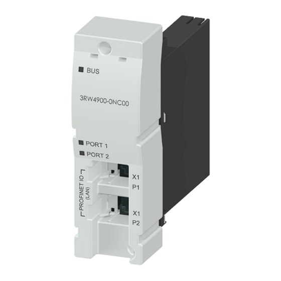
Dimension drawings PROFINET communication module Figure 9-1 Communication Module 3RW4900-0NC00 PROFINET Communication Module for SIRIUS Soft Starter 3RW44 Manual, 12/2013, A5E31996495002A/RS-AA/001... -
Page 70: Profinet Communication Module With Connectors
Dimension drawings 9.2 PROFINET communication module with connectors PROFINET communication module with connectors Figure 9-2 PROFINET communication module in installed/connected state with straight connectors PROFINET Communication Module for SIRIUS Soft Starter 3RW44 Manual, 12/2013, A5E31996495002A/RS-AA/001... - Page 71 Dimension drawings 9.2 PROFINET communication module with connectors Figure 9-3 PROFINET communication module in installed/connected state with angled connectors PROFINET Communication Module for SIRIUS Soft Starter 3RW44 Manual, 12/2013, A5E31996495002A/RS-AA/001...
- Page 72 Dimension drawings 9.2 PROFINET communication module with connectors PROFINET Communication Module for SIRIUS Soft Starter 3RW44 Manual, 12/2013, A5E31996495002A/RS-AA/001...
-
Page 73: Circuit Diagram Example
Circuit diagram example Figure 10-1 Control via PROFINET with switchover to manual operation local mode (e.g., at the control cabinet) PROFINET Communication Module for SIRIUS Soft Starter 3RW44 Manual, 12/2013, A5E31996495002A/RS-AA/001... - Page 74 Circuit diagram example PROFINET Communication Module for SIRIUS Soft Starter 3RW44 Manual, 12/2013, A5E31996495002A/RS-AA/001...
-
Page 75: Appendix
Appendix Data formats and data records A.1.1 Process data and process images Process image The process image is a component of the system memory of the CPU. At the start of the cyclic program, the signal states of the inputs are transferred to the process image of the inputs. - Page 76 Appendix A.1 Data formats and data records Process data Process image: (16 O, DO 0.0 to DO 1.7) (16 I, DI 0.0 to DI 1.7) Outputs ⇐ DO 1.2 Parameter set bit 0 ⇐ DO 1.3 Parameter set bit 1 DO 1.4 Not assigned DO 1.5...
- Page 77 Appendix A.1 Data formats and data records Alarms Data that are transferred from the soft starter and that indicate the current operating status, e.g., Motor left, etc. Data format: Bit Diagnostics Data that are transferred from the soft starter and that indicate the current operating status, e.g., Overload fault, etc.
- Page 78 Appendix A.1 Data formats and data records Statistics data for device service life ● Operating hours The soft starter records 2 operating hour values: – The operating hours of the motor. This indicates how long the motor was switched on. –...
- Page 79 Appendix A.1 Data formats and data records The following data are available as a maximum pointer: ● Number of overload trips. ● Phase current I to I and I to I . Maximum and minimum phase current as L1max L3max L1min L3min a percentage [%] of set current I...
-
Page 80: Data Record 68 - Read/Write Process Image Of The Outputs (Pio)
Appendix A.1 Data formats and data records Byte arrangements When data longer than one byte is stored, the bytes are arranged as follows ("big endian"): A.1.2 Data record 68 - Read/write process image of the outputs (PIO) Note Note that data record 68 is overwritten by the cyclic process image in automatic mode! Byte Meaning Header... - Page 81 Appendix A.1 Data formats and data records Process data Process image (16 O (outputs), DO 0.0 to DO 1.7) DO 0.0 Motor right DO 0.1 Motor left DO 0.2 Not assigned (brake) DO 0.3 Trip Reset DO 0.4 Emergency start DO 0.5 Not assigned (self-test) DO 0.6...
-
Page 82: Data Record 69 - Process Image Of The Inputs (Pii)
Appendix A.1 Data formats and data records A.1.3 Data record 69 - Process image of the inputs (PII) Byte Meaning Process image of the inputs Process data DI 0.0 to DI 0.7, table below Process data DI 1.0 to DI 1.7, table below Reserved = 0 Reserved = 0 Process data... -
Page 83: Data Record 72 - Log List - Read Device Error
Appendix A.1 Data formats and data records A.1.4 Data record 72 - Log list - Read device error Byte Meaning Value range Increment Comment 0 ... 3 Operating hours 0 … 2 1 second Entry 1 = oldest device entry 4 ... -
Page 84: Data Record 73 - Log List - Read Trips
Appendix A.1 Data formats and data records A.1.5 Data record 73 - Log list - Read trips Byte Meaning Value range Increment Comment 0 ... 3 Operating hours 0 ... 2 1 second device Entry 1 = oldest 4 ... 5 Object number 0 ... -
Page 85: Data Record 75 - Log List - Read Events
Appendix A.1 Data formats and data records Object No. Trips alarms 1408 No load 1409 Loss of phase L1 1410 Loss of phase L2 1411 Loss of phase L3 1421 Impermissible I /CLASS setting 1479 Phase angle control failure 1481 System voltage too high 1482 Current measuring range exceeded... -
Page 86: Data Record 81 - Read Basic Setting Of Data Record 131
Appendix A.1 Data formats and data records The following alarms can be entered: Object No. Events alarms Comment Warnings Temperature sensor overload ± Temperature sensor wire break ± Temperature sensor short-circuit ± Thermal motor model overload ± Current limit exceeded ±... -
Page 87: Data Record 83 - Read Basic Setting Of Data Record 133
Appendix A.1 Data formats and data records A.1.9 Data record 83 - Read basic setting of data record 133 Data record 83 corresponds in structure and content to data record 133. Data record 83 supplies the default values for all parameters of data record 133. A.1.10 Data record 92 - Read device diagnostics Byte... - Page 88 Appendix A.1 Data formats and data records Byte Alarm bit Error No.*) Meaning/acknowledgment Protective function: Motor / cable / short-circuit Temperature sensor overload 4, 24 Overload detected, alarm bit is updated continually. Temperature sensor wire break 6, 24 Thermistor circuit interrupted, alarm bit is updated continually.
- Page 89 Appendix A.1 Data formats and data records Byte Alarm bit Error No.*) Meaning/acknowledgment Reserved = 0 4...7 Ground fault detected Ground fault is present, alarm bit is updated continually. Ground fault tripping 9, 24 Tripping of motor due to ground fault. Alarm bit is deleted when the cause of tripping has been eliminated and acknowledged with "Trip Reset".
- Page 90 Appendix A.1 Data formats and data records Byte Alarm bit Error No.*) Meaning/acknowledgment Parameters Parameter assignment active Alarm bit is updated continually. Incorrect parameter value 16, 24 Alarm bit is always deleted when acknowledged with "Trip Reset" or valid parameters have been received. Parameters cannot be changed in ON state Attempted parameter change while motor is running or during relevant device function,...
- Page 91 Appendix A.1 Data formats and data records Byte Alarm bit Error No.*) Meaning/acknowledgment Reserved = 0 17, 24 Loss of phase L1 17, 24 Loss of phase L2 17, 24 Loss of phase L3 17, 24 Main power rotation right Main power rotation left System voltage too high 17, 24...
- Page 92 Appendix A.1 Data formats and data records Byte Alarm bit Error No.*) Meaning/acknowledgment Reserved = 0 Reserved = 0 Prewarnings Reserved = 0 0...1 Prewarning limit - remaining time for tripping undershot Prewarning limit - motor heating overshot Reserved = 0 4...7 Reserved = 0 Reserved = 0...
-
Page 93: Data Record 93 - Write Commands
Appendix A.1 Data formats and data records A.1.11 Data record 93 - Write commands Structure of the command data record Byte Meaning Comment Header Coordination 0x20 Write via C1 channel (PLC) 1 ... 3 Reserved = 0 Command Number of commands Value range 1 ... -
Page 94: Data Record 94 - Read Measured Values
Appendix A.1 Data formats and data records A.1.12 Data record 94 - Read measured values Byte Meaning Value range/ [coding] Increment Comment Measured values Phase current I 0 ... 797 % / [0 ... 255] 3.125 % 8-bit current format Phase current I 0 ... -
Page 95: Data Record 95 - Read Statistical Data
Appendix A.1 Data formats and data records A.1.13 Data record 95 - Read statistical data Byte Meaning Value range/ [coding] Increment Comment Statistics Motor current I 0 ... 797 % / [0 ... 255] 3.125 % 8-bit current format max (%) Reserved = 0 2 ... -
Page 96: Data Record 96 - Read Maximum Pointer
Appendix A.1 Data formats and data records A.1.14 Data record 96 - Read maximum pointer Byte Meaning Value range/ [coding] Increment Comment Phase current I 0 ... 797 % / [0 ... 255] 3,125 % In bypass operation L1 min Phase current I 0 ... -
Page 97: Data Records 131, 141, 151 - Technology Parameter 2: Read/Write Record 1, 2, 3
Appendix A.1 Data formats and data records A.1.15 Data records 131, 141, 151 - Technology parameter 2: Read/write record 1, 2, 3 Byte Value Comment Header Coordination 0x20 Write via C1 channel (PLC) 1 ... 3 Reserved = 0 Object Byte Meaning Only in... - Page 98 Appendix A.1 Data formats and data records Object Byte Meaning Only in Value range/ [coding] Factor data record Temperature sensor monitoring No [0] • Yes [1] • 25 ... 26 Reserved = 0 Minimum current limit 18.75 ... 100 % [6 ... 32] 3.125 % Maximum current limit 50 ...
- Page 99 Appendix A.1 Data formats and data records Object Byte Meaning Only in Value range/ [coding] Factor data record Starting mode 0...3 Direct on line [0] • Voltage ramp [1] • Torque control [2] • Motor heating [3] • Voltage ramp + current limiting •...
- Page 100 Appendix A.1 Data formats and data records Object Byte Meaning Only in Value range/ [coding] Factor data record Output 1 action No action (default) [0] • Control source PIO DO 1.0 • output 1 [1] Control source PIO DO 1.1 •...
- Page 101 Appendix A.1 Data formats and data records Object Byte Meaning Only in Value range/ [coding] Factor data record Stopping torque 10 ... 100 % [2 ... 20] Reserved = 0 Reserved = 0 Motor thermal capacity 1 ... 100 % [1 ... 100] 126 ...
-
Page 102: Data Records 132, 142, 152 - Technology Parameter 3: Read/Write Record 1, 2, 3
Appendix A.1 Data formats and data records A.1.16 Data records 132, 142, 152 - Technology parameter 3: Read/write record 1, 2, 3 Byte Value Comment Header Coordination 0x20 Write via C1 channel (PLC) 1 ... 3 Reserved = 0 Object Byte Meaning Value range [coding]... -
Page 103: Data Record 165 - Read/Write Comment
Appendix A.1 Data formats and data records Object Byte Meaning Value range [coding] Factor Brightness lighting 4...7 Lighting on [0] • Off with time delay [4] • Off [5] • Contrast display 0 ... 100 % [0 ... 20] Response of LEDs to fault 0...3 Unchanged [0] •... -
Page 104: Opc Ua Variables
OPC UA variables Node ID The variables can be accessed as follows: ns=http://siemens.com/automation/simocode/3rw44pn;i=Node ID of the relevant variable. Example: You want to access the RMS motor current in phase L1. You search for the Node ID of tag of variable "Phase current I (rms)"... - Page 105 Appendix A.1 Data formats and data records Node ID Coding Meaning Bool Phase angle control failure Bool Electrical braking active Bool DC braking active Bool Dynamic braking active Bool Emergency start active Diagnostics - Protection Bool Overload tripping Bool Prewarning limit - remaining time for tripping undershot Bool Prewarning limit - motor heating overshot Bool...
- Page 106 Appendix A.1 Data formats and data records Node ID Coding Meaning Diagnostics - Communication Bool Process image error Bool Automatic mode Bool Manual mode bus Bool Manual mode bus - PC controls Bool Manual mode local Bool Manual mode local - Input controls Bool Manual mode local - HMI controls Bool...
- Page 107 Appendix A.1 Data formats and data records Node ID Coding Meaning Unsigned Word Line-to-line voltage U (rms) L1-L2 Unsigned Word Line-to-line voltage U (rms) L2-L3 Unsigned Word Line-to-line voltage U (rms) L3-L1 Signed DWord Phase current I (rms) Signed DWord Phase current I (rms) Signed DWord...
- Page 108 Appendix A.1 Data formats and data records Node ID Coding Meaning Signed DWord Phase current I (rms) L1 min Signed DWord Phase current I (rms) L2 min Signed DWord Phase current I (rms) L3 min Signed DWord Phase current I (rms) L1 max Signed DWord...
- Page 109 Appendix A.1 Data formats and data records Node ID Coding Meaning Bool Parameter set Bit 0 (read) Bool Parameter set Bit 1 (read) Bool Disable quick stop (read) PROFINET Communication Module for SIRIUS Soft Starter 3RW44 Manual, 12/2013, A5E31996495002A/RS-AA/001...
-
Page 110: List Of Abbreviations
Appendix A.2 List of abbreviations List of abbreviations Abbreviation Meaning Operator control and monitoring station Binary Unit System System for transferring data between multiple nodes Certificate Authority Certificate authority China Compulsory Certification. The CCC certificate is the compulsory Chinese certificate for various product groups, especially electronic products and products in the automobile industry. - Page 111 Appendix A.2 List of abbreviations Abbreviation Meaning International Electrotechnical Commission International Electrotechnical Commission IO controller Controller used as component of PROFIBUS IO Internet Protocol IPsec Internet Protocol Security IRTtop Isochronous Real-Time Communication Light emitting diode LLDP Link Layer Discovery Protocol Vendor-neutral Layer 2 protocol MAC address Media Access Control address...
- Page 112 Appendix A.2 List of abbreviations Abbreviation Meaning Association for Electrical, Electronic and Information Technologies (Germany) Verein Deutscher Ingenieure (Association of German Engineers) Virtual private network PROFINET Communication Module for SIRIUS Soft Starter 3RW44 Manual, 12/2013, A5E31996495002A/RS-AA/001...
-
Page 113: Correction Sheet
Have you noticed any errors while reading this manual? If so, please use this form to tell us about them. We welcome comments and suggestions for improvement. Fax response From (please complete): Name SIEMENS AG I IA CE MK&ST 3 Company/Department 92220 Amberg / Germany Address... - Page 114 Appendix A.3 Correction sheet PROFINET Communication Module for SIRIUS Soft Starter 3RW44 Manual, 12/2013, A5E31996495002A/RS-AA/001...
-
Page 115: Glossary
Glossary Device name Before an IO device can be addressed by an IO controller, it must have a device name since its IP address is a fixed address assigned to the device name. This approach has been chosen for PROFINET because names are easier to manage than complex IP addresses. - Page 116 Glossary IP address In order for a PROFINET device to be addressed as an Industrial Ethernet node, it must also have an IP address that is unique within the network. The IP address consists of 4 decimal numbers, each ranging from 0 to 255, separated by dots. The IP address is composed of ●...
- Page 117 Glossary OLE for Process Control - industrial standard that defines vendor-neutral access to industrial communication networks on the basis of OLE. OPC (OLE for Process Control) refers to a standard interface for communication in automation engineering. With OPC, you can access OLE (Object Linking and Embedding). OLE is a component model of Microsoft.
- Page 118 Glossary PROFINET PROFINET (Process Field Network) is the open Industrial Ethernet standard of Profibus & Profinet International (PI) for automation. Within the framework of Totally Integrated Automation (TIA), PROFINET is a consistent continuation of: ● PROFIBUS DP, the established fieldbus ●...
-
Page 119: Index
Index 3RW44 Data records, 79 Control inputs, 21 Data security, 14 Display, 21 Data transmission Interface, 21 Acyclic, 45 Menu, 22 Cyclic, 45 Motor status, 21 Device configuration, 34 PC via Bus, 21 Device interface, 27 PLC via fieldbus, 21 Device name, 28, 36 User levels, 21 Device service life, 78... - Page 120 Index Establishing a connection, 52 Supported services, 52 Initial commissioning, 32 Operating instructions Installation, 24 3RW44 soft starter, 10 Installation altitude, 67 PROFINET communication module, 10, 23 Interrupts Overload trip, 79 Diagnostic interrupt, 60 Evaluating, 60 Triggering, 60 IO controller, 18 IO device, 18 Parameter settings IP address, 37, 55...
- Page 121 Index Write, 51 RJ45 socket, 25 Router address, 38 Write access, 51 Security settings, 52 SIMATIC S7, 60 Simple Network Management Protocol, 58 SNMP, 58 Standards, 67 STEP 7, 17, 27 Subnet mask, 37 Substitute value, 41 Target group, 9 Technical Assistance, 11 Test version, 28 Time synchronization...
- Page 122 Index PROFINET Communication Module for SIRIUS Soft Starter 3RW44 Manual, 12/2013, A5E31996495002A/RS-AA/001...
- Page 124 Contact for all technical information: Technical Assistance Tel.: +49 (911) 895-5900 e-mail: technical-assistance@siemens.com www.siemens.com/sirius/technical-assistance Siemens AG Subject to change without prior notice Industry Sector 3ZX1012-0RW40-0AC0 Postfach 23 55 90713 FUERTH © Siemens AG 2013 GERMANY Industrial Controls SIRIUS www.siemens.com/automation...
Need help?
Do you have a question about the SIRIUS PROFINET and is the answer not in the manual?
Questions and answers