
Related Manuals for Motorola HC700-G


Summary of Contents for Motorola HC700-G
- Page 1 HC700-G & HCe700-G Handheld Computers Models F4708A (HC700-G) & F4707A (HCe700-G) User Manual...
-
Page 3: Table Of Contents
Waste (Disposal) of your Electronic and Electric Equipment 22 Eye Safety Standard for Imager Engines 22 Trademarks 24 Internet Links 24 What is the HC700-G Handheld Computer? 1 Unpacking 4 Front Panel and Top Side Features 8 Rear and Bottom Side Features 10... - Page 4 Using the Keypad 33 Keypad Backlight 36 Screen Backlight 36 Adjusting Earpiece/Speaker Volume 37 Voice Recording 38 Resetting the HC700-G 39 Persistent Registry Reset (Clean Registry) 40 miniSD Memory Card 41 Installing a miniSD Card 41 miniSD Card Handling Precautions 42...
- Page 5 Battery Replacement 58 Battery Maintenance 60 Battery Disposal 61 Updating the Software 61 Update Image 61 See how much memory is available 61 Remove programs 62 See available storage card memory 62 Automatically save files on a storage card 62 Overview of Phone 63 SIM Card Installation 63 Wireless Manager 65...
- Page 6 Use Call Waiting 76 Mute a call 76 Turn the phone on and off 77 View available networks 77 Put a call on hold 77 To put a call on hold, tap Hold. 77 Assign a ring tone to a contact 77 Copy a contact from a SIM to a device 78 Limit calls to specific area codes or phone numbers 78 Add a network 78...
- Page 7 Accept a Bluetooth partnership 101 Use a Bluetooth phone as a modem 101 Create a Bluetooth partnership 102 End a Bluetooth partnership 103 Make your HC700-G visible 103 Receive a Bluetooth beam 103 Rename a Bluetooth partnership 104 Turn on and off Bluetooth 104...
- Page 8 Vehicle Power Adapter 137 Charging Inside the Vehicle 137 Protection Fuse 138 Charging Temperature 138 HC700 Vehicle Cradle 139 Charging the HC700-G Battery 139 Cradle Connections 140 Charging Temperature 141 Mounting the Cradle 142 USB Cable 144 Administering the Cradle Using Telnet 145...
- Page 9 Configuring the Cradle 148 General Menu (1.1) 149 Network Menu (1.2) 150 Event Log Configuration Menu (1.3) 151 Configuring the SNMP Agent (1.4) 152 Telnet Access Menu (1.5) 152 2.2 Event Log Interaction Menu 154 2.3 Status Menu 156 2.4 Restart Cradle 159 2.5 Set Date &...
-
Page 10: Computer Software Copyrights
No duplication or distribution of this document or any portion thereof shall take place without the express written permission of Motorola. No part of this manual may be reproduced, distributed, or transmitted in any form or by any means, electronic or mechanical, for any purpose without the express written permission of Motorola. -
Page 11: Commercial Warranty
Product Accessories One (1) Year Motorola, at its option, will at no charge either repair the Product (with new or reconditioned parts), replace it (with a new or reconditioned Product), or refund the purchase price of the Product during the warranty period provided it is returned in accordance with the terms of this warranty. - Page 12 This warranty sets forth the full extent of MOTOROLA’s responsibilities regarding the Product. Repair, replacement or refund of the purchase price, at MOTOROLA’s option, is the exclusive remedy. THIS WARRANTY IS GIVEN IN LIEU OF ALL OTHER EXPRESS WARRANTIES. IMPLIED...
- Page 13 E. A Product subjected to unauthorized Product modifications, disassemblies or repairs (including, without limitation, the addition to the Product of non-Motorola supplied equipment) which adversely affect performance of the Product or interfere with Motorola's normal warranty inspection and testing of the Product to verify any warranty claim.
- Page 14 A. that MOTOROLA will be notified promptly in writing by such purchaser of any notice of such claim; B. that MOTOROLA will have sole control of the defense of such suit and all negotiations for its settlement or compromise; and C.
-
Page 15: Notational Conventions
Notational Conventions Throughout this publication, you will notice the use of cautions and notes. These notations are used to emphasize that safety hazards exist, and care must be taken. CAUTION Indicates a potentially hazardous situation which, if not avoided, may result in minor or moderate injury. - Page 16 2402 - 2480 MHz 1 mW Changes or modifications made in the handheld computer, not expressly approved by Motorola, will void the user's authority to operate the equipment. Caution Wi-Fi Certification This product is certified: IEEE 802.11b, IEEE 802.11g, WPA, WPA2 and EAP.
- Page 17 For detailed product safety and RF exposure refer to Safety and General Information leaflet, Motorola publication Number 6802979C37.
- Page 18 DECLARATION OF CONFORMITY Per FCC CFR 47 Part 2 Section 2.1077(a) Responsible Party Name: Motorola, Inc. Address: 8000 West Sunrise Boulevard, Plantation, FL 33328 USA Phone Number: 1 (800) 453-0920 Hereby declares that the product: Product Name: HC700G Model Number: F4708A...
- Page 19 73/23/EEC Low Voltage Directive. You can view your product's Declaration of Conformity (DoC) to Directives 89/336/EEC and 73/23/ EEC at www.motorola.com/rtte - to find your DoC, enter the product Approval Number from your product's label in the "Search" bar on the Web site.
- Page 20 2402 - 2480 MHz 1 mW Changes or modifications made in the handheld computer, not expressly approved by Motorola, will void the user's authority to operate the equipment. Caution HCe700-G (EU) Transmission Modes HC700-G contains GPRS, WLAN and BT radios.
-
Page 21: Waste (Disposal) Of Your Electronic And Electric Equipment
Eye Safety Standard for Imager Engines The HC700-G and the HCe700-G is manufactured with the following Imager Engine options: - 5300 series with Laser aiming technology. - 5100 series with light emitting diodes aiming technology. - Page 22 The Standard also recommends that the following be included in user documentation: Use of controls or adjustments or performance of procedures other than those specified herein may result in hazardous radiation exposure. Caution Note: This warning states that altering the inner parts of the scanner in a way not specified in the user guide may cause light levels to exceed Class 1 limits.
-
Page 23: Trademarks
© Motorola, Inc. 2007. Wi-Fi and the Wi-Fi CERTIFIED logo are registered trademarks of the Wi-Fi Alliance. Internet Links This manual contain links to Motorola and third party web sites. Please note that internet links are subject to change. -
Page 24: What Is The Hc700-G Handheld Computer
Microsoft.NET Compact Framework 2.0 technology. The HC700-G has two models: the HC700-G model is the USA version and the HCe700-G model is the European/Asian version. This manual refers to all models as HC700-G. - Page 25 A drained battery can be replaced without data loss from the HC700-G memory. A built-in power source, independent of the battery pack, maintains the data in the HC700-G memory for at least 30 minutes until a charged battery is placed.
- Page 26 What is the HC700-G Handheld Computer?
-
Page 27: Unpacking
Carefully unpack each item from the shipping carton. Check all items for shipping damage, and check that you have received all items ordered. Note: Retain the original carton packaging in the event that the HC700-G should need to be returned for service. - Page 28 Unpacking...
- Page 29 Welcome...
- Page 30 HC700-G Features CHAPTER 2...
-
Page 31: Front Panel And Top Side Features
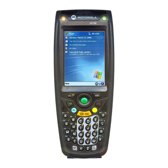
HC700 devices. The maximum speed is 115kbps. (The current models do not HC700-G - Front Panel and Top Side Features FIGURE 1. support IrDA communication). Speaker - integrated speaker for sound playback (The current models do not support Phone sound). - Page 32 Front Panel and Top Side Features Main Scan/Picture Key. In Suspend mode, pressing the SCAN key wakes-up the HC700-G. Microphone - integrated microphone that provides audio input for phone and voice recording. Application LED - programmable indication LED. Earpiece - integrated audio earpiece when using the HC700-G as a phone.
-
Page 33: Rear And Bottom Side Features
When connected to a power source, the HC700-G battery is charged via this connector. The connector also enables the following communication HC700-G - Rear and Bottom Side Features connections: full serial RS232, USB FIGURE 2. 1.1 and Ethernet 10/100. - Page 34 Rear and Bottom Side Features...
- Page 35 HC700-G Features...
-
Page 36: Starting To Work
CHAPTER 3 Starting to Work The HC700-G is shipped with a plastic film used for protecting the screen and the IrDA window. Before usage, remove the protective film from the screen and the IrDA window. To avoid damage to the screen, do not use a sharp object to remove the protective film. -
Page 37: Using The Touch Screen
Starting to Work The Motorola logo will show on the screen for about 30 seconds and Windows Mobile screen will appear. The Windows Mobile screen will instruct you to tap on the screen and to follow the Align Screen procedure (touch screen calibration). - Page 38 Using the Touch Screen Motorola recommends using a screen protector to minimize wear and avoiding damage. A screen protector is applied to the HC700-G screen surface. Screen protector provides: • Scratches and marks protection • Tactile feel when writing or tapping on the screen •...
-
Page 39: Align Screen Procedure
You are prompted to align the screen by tapping the cross five times (see Figure 6). Use only the stylus supplied with your HC700-G. Make sure to tap at the center of the target to ensure accurate calibration. Press the stylus firmly once and release. -
Page 40: Turning On
The Power button is disabled while the HC700-G is in cradle or connected to an external power source. Important: Do not press the Power Button when the HC700-G is out of the cradle and the Status LED (inside the Power button) illuminates red. -
Page 41: Attaching The Hand-Strap
To attach the hand-strap to the back of the HC700-G, perform the following: Turn over the HC700-G to view the back side and insert the U shaped clip of the hand-strap into the notches on the imager housing (see Figure 9). -
Page 42: Windows Mobile Basics
Windows Mobile Basics Today Screen When the HC700-G powers-on for the first time, you see the Today screen. The Today screen shows a summery of important information regarding your daily activities and serves as a start point for setting and operating the HC700-G. When working with the HC700-G, you can always display the Today screen by tapping Start >... -
Page 43: Status Bar, Start Menu And Command Bar
Start > Settings > Menus. The mid section shows a list of the most recently used programs. The lower section is used for the entering the HC700-G Programs folder and Setting the device. -
Page 44: Customize The Start Menu
Windows Mobile Basics Customize the Start menu You can choose which items appear in the Start menu. To customize the Start menu, perform the following: Tap Start > Settings > Personal tab > Menus. Select the check boxes of the items you want to appear in the Start menu. You can select up to seven items. - Page 45 Starting to Work Calls are forwarded Call on hold Missed call Battery level Low battery Battery charging No battery Signal strength No signal Roaming Sync error Radio off Radio connected Speaker on...
- Page 46 Windows Mobile Basics Speaker off Bluetooth on Wi-Fi on Wi-Fi data call...
- Page 47 Starting to Work...
-
Page 48: Suspend Mode
Suspend Mode Shifting to Suspend Mode To manually shift to Suspend mode - while the HC700-G is turned on, momentarily press the Power Button (see Figure 1). In Suspend mode, the battery power is conserved by automatically turning off the display and the computer sections of the HC700-G. -
Page 49: Waking-Up From Suspend Mode
Using the HC700-G G is powered by an external power charger, or from 0 to 1 minute when the HC700-G is running only on battery power (see Figure 12). Configuring time-out for entering Suspend mode FIGURE 12. Important: • The HC700-G does not enter automatically to Suspend mode while in the cradle •... -
Page 50: Waking-Up From Suspend Mode
• Connecting or removing the USB cable to/from the external connector • Connecting power to the Cradle Interface Connector • The HC700-G generates an alarm indication Note: Tapping on the touch screen or pressing the keypad keys does not wake-up the HC700-G. -
Page 51: Turning Off
Turn off the HC700-G when not in use for long duration and when charging is not available. Important: When the HC700-G is out of the cradle, do not attempt to turn off the unit when the Status LED (inside the Power button) shows red. Pressing the Power button when the Status LED shows red (system initialization), may cause damage to the operating system. -
Page 52: Resuming Operation
If the HC700-G is left for more than 5 minutes, Cold reset (See “Cold Reset” on page 39.) will be performed. During Cold reset, the status LED, inside the Power button, illuminates red for about 6... -
Page 53: How To Save Battery Power
How to Save Battery Power Use the following guidelines to save battery power: • When not in use, dock the HC700-G in a cradle or connect to any power source • Set the HC700-G to turn off automatically after a short period of non-use •... -
Page 54: Led Indications
LED Indications LED Indications The HC700-G has two LED indicators. The Status LED indicates power related status. The Application LED is an application notification LED. This LED is designed to be programed according to specific requirements. The Status LED The status LED, located inside the Power Button... -
Page 55: The Application Led
Using the HC700-G Status LED indications when HC700-G is docked inside the cradle The Status LED indications, when HC700-G is docked inside the cradle, are listed in Table 2 Status LED indications when HC700-G is docked in the Cradle TABLE 2. -
Page 56: Using The Keypad
Keys active when in Alphabetic mode, which are those seen on the overlay of the HC700-G key- pad. Keys active when in Shift or Function mode which are those seen next to each key on the HC700-G keypad panel. Press the key to toggle between the Alphabetic and Numeric keypad modes. - Page 57 Using the HC700-G Key assignment The key assignment of the HC700-G keypad is listed in Table 3 . HC700-G - Key Assignment TABLE 3. Function Use the <TAB/Send> key to make & answer phone calls. The key also serves as <TAB>...
- Page 58 The <SHIFT> is also used for screen and keypad illumination page 36. The Application <P1/P2> key functionality is set by the software application running on the HC700-G. Use the <SHIFT> key to toggle between P1 and P2. To learn more about these keys, consult the software application guide.
-
Page 59: Keypad Backlight
Using the HC700-G Keypad Backlight Turning backlight on/off • To turn on - hold down the <SHIFT> key for four seconds and release - the keypad backlight will turn on. • To turn off - hold down the <SHIFT> key for two seconds - the keypad backlight will turn off. -
Page 60: Adjusting Earpiece/Speaker Volume
LED Indications Adjusting Earpiece/Speaker Volume You can adjust the Earpiece/Speaker volume for sounds, such as the sound you hear when you make a phone call, replay audio, scan bar codes or when you tap on the screen. Important: Phone calls are routed only through the earpiece. Earpiece/Speaker volume can be adjusted by one of the following methods: Using the Earpiece/Speaker Volume keys (see Fig-... -
Page 61: Voice Recording
Using the HC700-G Voice Recording To record sound, press the Voice Recording button - the Notes application will run, enabling you to record and play sounds. To assign different functionality to this button, go to: Voice Recording Button Start Menu > Settings > Personal > Buttons. -
Page 62: Resetting The Hc700-G
30 seconds and then Windows Mobile desktop or application screen will appear - the HC700-G functions again. Warm Reset can also be performed in the following way: go to: Start Menu > TaskManager and tap on “Soft Reset”. -
Page 63: Persistent Registry Reset (Clean Registry)
To reset the persistent registry, perform Cold Reset and than, immediately, before the HC700-G boots- up, hold down the <S> and <X> and <H> keys for 5 seconds. The HC700-G will boot-up, showing the Motorola logo on the screen with the following line of text on the upper left corner: “clean registry... -
Page 64: Minisd Memory Card
Memory Card miniSD Memory Card Note: When using the HC700-G with Windows Mobile 2003 operating system, The memory size of the miniSD memory card is limited to a maximum of 1GB. Installing a miniSD Card Important: Turn off the HC700-G before removing or installing the miniSD (Secure Digital) card. -
Page 65: Minisd Card Handling Precautions
• Do not store the miniSD card in locations subjected to high humidity or temperatures Allocating Memory You can allocate the HC700-G memory by setting the size of the storage and the programs memory. You can also view the amount of memory used by running programs or storage space. To view and... -
Page 66: Scanning Barcodes
Scanning Barcodes Scanning Barcodes The HC700-G houses a digital camera (imager) that scans the most commonly used 1D and 2D bar- codes (depend on your imager option). The HC700-G and the HCe700-G are manufactured with the following imager engine types: •... - Page 67 Using the HC700-G About 7 inches from barcode ± 40 degrees Aim the green light bar at the barcode Red Ambient Light Scan/Picture Key Scan/Picture Keys Capturing bar codes with LED aimer imager FIGURE 23.
- Page 68 ° daily work. The green aiming bar can be positioned at any angle across the bar code symbol. Key scanning concepts There are four key concepts related to bar code reading with the HC700-G. • Aiming • Distance • Motion...
- Page 69 Note that when the HC700-G is held closer to the bar code the aiming pattern appears smaller and when held farther from the bar code it appears larger. Bar code symbols with dense symbol elements should be read closer to the HC700-G while large bar HC700-G with larger symbol elements should be read at a larger distance (Depth-of-Focus) from the HC700-G.
-
Page 70: Bar Code Types
Scanning Barcodes Angle The angle of the bar code in relation to the imager is a factor in reading performance. The device is designed to read typical bar code over a range of side angles from about -40° to +40°. Note: When adjusting your position, you may rotate the wrist left or wright and pitch by dropping or lifting the wrist. - Page 71 Using the HC700-G Sample bar codes Use the following bar code samples, shown in Table 5 , to experiment scanning and decoding. Sample bar codes TABLE 5. Bar code type Bar code sample UPC A CODE 93 EAN 8 Interleaved 2 of 5...
- Page 72 Scanning Barcodes Sample bar codes TABLE 5. Bar code type Bar code sample CODE 128 CODABAR USS-128 Code 39 @1234567@ PLESSEY UCC/EAN 128...
- Page 73 Using the HC700-G Sample bar codes TABLE 5. Bar code type Bar code sample INTERLEAVED 2 of 5 2 of 5 CODABAR PDF417 Datamatrix...
-
Page 74: Capturing Images
To demonstrate a signature capture, print and use the Signature Capture Form (see Figure 26). Hold the HC700-G 6 to 9 inches from the form, so that the signature and the bar code are in the imager’s field of view. - Page 75 Position the green aiming bar between the signature and the bar code (see Figure 28). The HC700- G identifies the signature area, using the bar code on the lower part of the form as reference point. To capture again, use one of the HC700-G scan buttons. Capturing Images - Aiming FIGURE 28.
-
Page 76: Save Picture In Memory
• When outdoors the green aiming bar light may not be visible • The image presented on the screen generally shows with lower quality than the one stored on the HC700-G and sent over to the server. Save picture in memory After an image had been captured you may want to save it directly in the memory. -
Page 77: Scanning With Laser Aimer Imager
Run the Bcr barcode reader application: Start Menu -> Programs -> Sample Applications -> Bcr. Aim and hold the HC700-G at about 7 inches from the target. Press one of the Scan/Picture keys and adjust your position to place the emitted red pattern at the target. - Page 78 Scanning Barcodes The HC700-G supports 360 omni-directional capture for easy use in daily work. The aiming pattern ° can be positioned at any angle across the barcode symbol (see Figure 32). Laser Aimer Imager - Barcode Capture Positions FIGURE 32.
-
Page 79: Charging The Battery
Using the HC700-G Charging the Battery The battery is charged when the HC700-G is docked in cradle. A fully charged battery provides 10 hours of typical usage or 24 hours in Standby mode. The charging status of the spare battery is indicated by the Spare battery Status LED. -
Page 80: Checking The Remaining Battery Power
Charging the Battery Checking the Remaining Battery Power To the status of the remaining battery power is shown as an icon on the upper status bar and pops-up as a message at the bottom of the screen (see Figure 33). Sufficient Battery Power Battery Power Low Battery Power Very Low... -
Page 81: Routine Battery Charge
Make sure that the HC700-G is powered off (See “Turning Off” on page 28.). Remove the HC700-G hand-strap. Press the battery snap on the battery (see Figure 35) and pull away the battery from the HC700-G. Insert a fresh battery, bottom end first, into the battery compartment. - Page 82 Charging the Battery Press the Power Button - the HC700-G is now ready for use. Battery Snap Hand-strap Battery Compartment Battery Installation and Removal FIGURE 35. Battery Safety The battery or HC700-G may carry warning symbols, defined as follows: Important safety information will follow.
-
Page 83: Battery Maintenance
The performance of the battery depends on the way the battery is treated. Therefore, to comply with Motorola Warranty for batteries and to assure high performance and a long life for the rechargeable battery, please read and follow the battery maintenance instructions described in the following sections. -
Page 84: Battery Disposal
Updating the Software To ensure maximum service life of the HC700-G, always replace the battery with a genuine Motorola replacement. Battery Disposal Batteries must be recycled or disposed of properly in accordance with local requirements. Recycling facilities may not exist in all areas. Please contact your local environmental agency for more information regarding proper disposal. -
Page 85: Remove Programs
Using the HC700-G Remove programs You can only remove programs that you installed. Programs that come with your HC700-G cannot be removed. To remove a program, perform the following: Tap Start > Settings > System tab > Remove Programs. In the Programs in storage memory list, select the program you want to remove, and tap Remove. -
Page 86: Overview Of Phone
SIM Card Installation Before using the HC700-G as a phone, make sure that your HC700-G is equipped with a SIM (Subscriber Identity Module) card. SIM card is a small smart card that fits inside the HC700-G. The SIM card holds the personalized information about its user, including the network activation and even phone book entries. - Page 87 Using the Phone Lower the SIM card holder and press downward to lock the SIM card holder. Close the SIM card door install the battery. Perform Cold Reset. SIM Card Installation FIGURE 36.
-
Page 88: Wireless Manager
Wireless Manager Before making a call, connecting to wireless network or sending files via Bluetooth, you should turn on the wireless radio using the Wireless Manager application. Start the Wireless Manager by performing the following: Antenna icon Tap on the antenna icon on the status bar (see Figure 37). -
Page 89: Switching On The Phone
Using the Phone Switching On the Phone Another way to turn on/off the GSM phone is via the radio setting application (see Figure 39). Before making a call, you should verify that the phone radio is turned on. To turn on the phone perform the following: Tap: Start Menu >... -
Page 90: Answer A Call
Answer a call To answer a call, tap Answer (see Figure 40). Answer a Call FIGURE 40. Tips: • When you receive a phone call, you have the option to ignore it. If you ignore the call, the phone will stop ringing and the caller may be sent to your voice mail, depending on your service provider. To ignore a call, tap Ignore. -
Page 91: Change Network Settings
Using the Phone To place an emergency call: If HC700 is in Suspend (screen is blank), press briefly on the Power button. Start and select Phone form the menu (see upper, left-hand side of the screen). Dial the emergency number by tapping the on-screen keys. Press the on-screen Talk key to call the emergency number. -
Page 92: Change The Ringer Volume
You can customize phone settings, such as the ring type and ring tone to be used for incoming calls, and the keypad tone to be used when entering phone numbers. You can also protect your phone from unauthorized use. You can customize phone settings, such as the ring type and ring tone to be used for incoming calls, and the keypad tone to be used when entering phone numbers. - Page 93 Using the Phone In the Ring tone list, tap the sound you want to use. Tip: to use custom .wav, .mid, or .wma files as ring tones, use ActiveSync on your PC to copy the file to the /Windows/Rings folder on your device. Then, select the sound from the Ring tone list. For more information on copying files to your device, see ActiveSync Help on your PC.
-
Page 94: Change The Ring Type
Change the ring type You can change the way that you are notified of incoming calls. For example, you can choose to be notified by a ring, a vibration, or a combination of both. From the Phone keypad, tap Menu > Options > Phone tab. In the Ring type list, tap the desired option (see Figure 42). -
Page 95: Enter A Voice Mail Or Text Message Phone Number
Using the Phone Enter a voice mail or text message phone number To use voice mail or send text messages (SMS), ensure that you enter the correct voice mail phone number or text message phone number in Phone settings. To use voice mail or send text messages (SMS), ensure that you enter the correct voice mail phone number or text message phone number in Phone settings. -
Page 96: Make A Call Using Speed Dial
Tip: to create a speed dial from Contacts, tap and hold the contact name, tap Add to Speed Dial, and then select an available location for the new speed dial. Make a call using speed dial Tap Start Menu > Phone. On the Phone keypad, tap and hold the speed dial number assigned to the contact you want to call. -
Page 97: Manually Select A Network
Using the Phone To view Call History, from the Phone keypad, tap Call History. To change the Call History view, tap Menu > Filter and select a different view. For example, you can view only missed or incoming calls. When you filter By Caller, you see a list of all contacts on your device who have a phone number assigned to them. -
Page 98: Set Preferred Networks
Tip: emergency calls can be placed at any time, without requiring a PIN. Set preferred networks You can set your preferred networks in the order you want your device to access them. For example, if your first preferred network is unavailable, your device will try to access your second preferred network. -
Page 99: Forward Calls
Using the Phone Tap Call Barring > Get Settings. Select the type of incoming and/or outgoing calls you want to block. Forward calls Use Call Forwarding to forward all incoming calls to a different number. From the Phone keypad, tap Menu > Options > Services tab. Tap Call Forwarding >... -
Page 100: Turn The Phone On And Off
Turn the phone on and off You can turn your phone on and off while keeping your device turned on. While using any program on your device, tap Tap Wireless Manager. Tap the Phone button to turn the phone off. If it is already turned off, the button is a lighter color and displays an icon marked with an X. -
Page 101: Copy A Contact From A Sim To A Device
Using the Phone Tap Menu > Edit. Tap Ring tone and tap the ring tone you want. Tap OK. Copy a contact from a SIM to a device Tap Start Menu > Contacts. Tap the contact. Tap Menu > Save to Contacts. Limit calls to specific area codes or phone numbers You can restrict your phone to dial only the phone number(s) or area code(s) that you specify in a Fixed Dialing list. - Page 102 Select Add a network from the list if you don't know the code of the network, and select a network from the list. Tap OK.
- Page 103 Using the Phone...
-
Page 104: Turning On/Off
Wireless LAN Connection CHAPTER 6 Turning On/Off Ensure that your HC700-G is within active Wireless LAN coverage. Note that in Flight Mode, Wireless LAN is turned off. Tap Start Menu -> Settings -> System tab (see Figure 45). Tap Wireless LAN Power icon. -
Page 105: Turn Wireless Power On Or Off
Wireless LAN Connection Turn wireless power on or off You can turn the power off to your wireless connections in a single location. This is a quick way to preserve bat- tery power or to prepare your device for an airplane flight. Tap Start >... -
Page 106: Connect To The Internet
Connect to the Internet Before you begin, obtain the following information from your Internet service provider (ISP) or wireless service provider: ISP server phone number or access point, user name, and password. Tap Start > Settings > Connections tab (see Figure 45). Connect to the Internet FIGURE 45. -
Page 107: Connect To Work
Wireless LAN Connection Connect to Work Before you begin, obtain the following information from your network administrator: server phone number, user name, and password. Tap Start > Settings > Connections tab. Do one of the following: •Tap Connections, and in My Work Network, set up a modem or VPN server connection. -
Page 108: Connect To Intranet Urls
Connect to intranet URLs If you want to connect to intranet sites that have periods in their URLs (for example, intranet.companyname.com), you must add them to the Work URL Exceptions list. Tap Start > Settings > Connections tab (see Figure 46). Tap Connections >... -
Page 109: View Intranet Urls
Wireless LAN Connection View intranet URLs Some companies use periods in their intranet URLs (for example, intranet.companyname.com). If you attempt to connect to one of these URLs, Internet Explorer Mobile will search for the Web site in the Internet rather than the company's intranet. To connect to such intranet URLs, they need to be entered as Work URL Exceptions. -
Page 110: Add A Dialing Location
Add a dialing location Tap Start > Settings > Connections tab. Tap Connections > Advanced tab > Dialing Rules. Tap New. In the Name box, enter a location name, for example, New York (see Figure 47). Enter or edit the area code and country code. If you have a pulse phone line, select the Pulse dialing check box. -
Page 111: Change Dialing Patterns
Wireless LAN Connection Change dialing patterns (see Figure 6) lists supported dialing patterns. list of supported dialing patterns TABLE 6. Enter Dial a country code Dial an area code Dial a local number Make an international call when using a GSM-network phone, the plus sign is + (plus sign) used to indicate that you are about to make an international call (rather than entering the international access number for the country you are in) -
Page 112: Change Network Card Settings
To connect faster when using a modem, clear the Wait for dial tone before dialing check box. To pay for calls with a credit card, in the Wait for credit card box, enter the number of seconds you want the device to wait for a credit card prompt, and enter the credit card number in the Extra dial- string modem commands box. -
Page 113: Configure Network Security Settings
Wireless LAN Connection Configure network security settings A wireless network can be added either when the network is detected, or manually by entering settings information. Before doing these steps, determine if authentication information is needed. To manually enter information, tap Start > Settings > Connections tab > Wi-Fi > Wireless tab. In Wireless networks, select the network you want to configure. -
Page 114: Enter New Settings
Tap Select Networks. In the appropriate lists, select My ISP or My Work Network. Enter new settings A wireless network can be added either when the network is detected, or manually by entering settings information. To manually enter information, tap Start > Settings > Connections tab > Wi-Fi > Wireless tab. Note that your device may say Wireless Ethernet or Network Cards instead of Wi-Fi. -
Page 115: Configure Advanced Proxy Settings
Wireless LAN Connection To create a new connection, in either My ISP or My Work Network, tap Add a new modem con- nection, and follow the instructions in the New Connection wizard. Enter a name for the connection, such as your company's name. In the Select a modem list, tap your modem type. -
Page 116: Set Up A Wireless Network
Set up a wireless network Tap Start > Settings > Connections tab > Wi-Fi > Wireless tab. Note that your device may say Wireless Ethernet or Network Cards instead of Wi-Fi. Do one of the following: If you do not see a desired network, tap Add New and follow the instructions on the screen. Any networks that you have already configured are preferred networks and are listed under Wire- less networks. -
Page 117: Set Up A Wap Gateway
Wireless LAN Connection Note: If you use your network card with two networks, such as a private network at work and one at home for the Internet, you will need to change the network to which the network card connects. Set up a WAP gateway To access WAP sites through Internet Explorer Mobile, configure your device to use a WAP gateway. -
Page 118: Set Up Proxy Server Settings
Tips: • To manually start a connection, tap and hold the connection, and tap Connect. • To delete a connection, tap and hold the connection you want to remove, and tap Delete. Set up proxy server settings If you are connected to your ISP or private network during synchronization, your device should download proper proxy settings during synchronization from your PC. -
Page 119: Use Dialing Rules
Wireless LAN Connection To change existing settings, in My Work Network, tap Manage existing connections > VPN tab. Select the desired VPN connection, tap Edit, and follow the instructions on the screen. To manually start a connection, tap and hold the connection, and tap Connect. To delete a connection, tap and hold the connection you want to remove, and tap Delete. -
Page 120: Set Up An Automatic Choice For Connections
put all of your corporate settings under My Work Network connections, you can change the name from My Work Network to your company's name. Tap Start > Settings > Connections tab > Connections. Under My ISP or My Work Network, tap Manage existing connections. Tap the General tab. - Page 121 Wireless LAN Connection...
-
Page 122: Overview Of Bluetooth
You can use Bluetooth as follows: • Beam information, such as files, appointments, tasks, and contact cards, between your HC700-G and other devices that have Bluetooth capabilities. -
Page 123: Turning The Bluetooth Radio On/Off
Bluetooth Connection Turning the Bluetooth radio On/Off Ensure that both Bluetooth devices are within 10 meters (30 feet) of each other and that both Bluetooth-enabled devices are discoverable. Note that in Flight Mode Bluetooth is turned off. Tap Start Menu > Settings > System tab (see Figure 48). Tap Bluetooth Enable/Disable icon (note that the default state of the Bluetooth radio is turned on). -
Page 124: Accept A Bluetooth Partnership
have Bluetooth turned on to exchange information; they do not need to be visible. For instructions on creating a partnership, see Create a Bluetooth partnership. You need only create a partnership once between two devices. Then, the devices can exchange information without your entering a passcode. -
Page 125: Create A Bluetooth Partnership
Next. Enter the same passcode on the phone. To give the partnership a more meaningful name, change the name of the device in Name to HC700-G. Tap Finish. In the My Connections list, tap the phone, and tap Next. -
Page 126: End A Bluetooth Partnership
Select the Turn on Bluetooth check box, and then select the Make this device visible to other devices check box. Tip: If you no longer want your HC700-G to be visible, clear the Make this device visible to other devices check box. -
Page 127: Rename A Bluetooth Partnership
Select or clear the Turn on Bluetooth check box. Note: By default, Bluetooth is turned off. If you turn it on, and then turn off your HC700-G, Bluetooth also turns off. When you turn on your HC700-G again, Bluetooth turns on automatically. -
Page 128: Set Up An Outgoing Bluetooth Com Port
If the port cannot be created, it is in use. Select a different numbered port. To use this COM port to communicate only with devices with which your HC700-G has a Blue- tooth partnership, select the Secure Connection check box. - Page 129 Here are some examples of how to use incoming and outgoing virtual COM ports. Outgoing COM port You have a program on your HC700-G that cannot use Bluetooth directly but can print to a serial (COM) port. You can create a Bluetooth partnership with a Bluetooth-enabled printer, and then set up an outgoing COM port (for example, COM 7).
-
Page 130: General
ActiveSync allows the HC700-G to be synchronized with a PC over USB. The program synchronizes Personal Information Manager (PIM) data such as Microsoft Outlook, along with Internet surfing. ActiveSync enables the manual transfer of files between the HC700-G and a PC and the ability to install and uninstall mobile device applications. -
Page 131: Routine Connection
ActiveSync (USB) Connectivity request you to point to the HC700-G USB driver provided with this product. The HC700 USB driver can also be downloaded from MOTODEV web site (https://developer.motorola.com/?path=1.870). Host PC Personal Desktop Cradle PC USB Port HC700-G USB Port ActiveSync - USB Connectivity FIGURE 49. -
Page 132: Change The Synchronization Schedule
Important note: The HC700-G power-down timer is reset each time you synchronize. If you schedule a synchronization interval that is shorter than the time interval set for the HC700-G to automatically power down, the HC700-G will never turn off to save battery power. -
Page 133: Start And Stop Synchronization
You can sync directly with Exchange Server using a connection to either a wireless network or a PC. In ActiveSync on the HC700-G, tap Menu > Configure Server. If you have not yet set up sync with Exchange Server, this will say Add Server Source. -
Page 134: What Happens To My Information When I Synchronize With Multiple Computers
What happens to my information when I synchronize with multiple computers? You can set up your HC700-G to synchronize with more than one PC or with a combination of one or more PCs and Exchange Server. When synchronizing with multiple computers, the items that you synchronize will appear on all of the computers with which they are synchronized. -
Page 135: Synchronizing Calendar, Contacts, And Tasks
Mobile workbooks, and Notes. To synchronize files, select the Files information type for synchronization in ActiveSync. The <device name> My Documents folder is created on the desktop of your PC. Place all files you want to synchronize with the HC700-G in this folder. Password-protected files cannot be synchronized. -
Page 136: Synchronize A Favorite Link
• Messages in the Outbox folder on your HC700-G are transferred to Exchange Server or Outlook and then sent from those programs. • When you delete a message on your HC700-G, it's deleted from your PC or Exchange Server the next time you synchronize. -
Page 137: Change E-Mail Security Options
ActiveSync can help you manage your e-mail by eliminating your main e-mail address when you reply to all senders from the HC700-G. This can reduce the number of e-mails you receive and synchronize by ensuring that you do not receive your own e-mail. -
Page 138: Troubleshoot An Activesync Cable Connection
Troubleshoot an ActiveSync cable connection Troubleshoot as described here if you are using a USB cable to connect your HC700-G to the PC, and ActiveSync does not recognize the HC700-G or the program stops responding (or hangs) while connecting to ActiveSync. Troubleshooting is often a matter of systematically testing the possible solutions, usually beginning with the simplest for speed and convenience and then moving on to more complex solution tasks. - Page 139 Connections, then open Network Connections •Right-click the local area connection created by ActiveSync, and click Properties. In the Connect using box, Windows Mobile-based HC700-G is displayed. •In This connection uses the following items, select every check box (to select all protocols).
-
Page 140: Hc700-G Diagnostics Application
CHAPTER 9 HC700-G Diagnostics Application The Diagnostic application is used to troubleshoot the HC700-G and isolate problems at assembly or component level. Using the application helps to determine if a problem originates from the hardware platform or software system and plan corrective action. Corrective action may include battery replacement, replacement of the miniSD card, cleaning of the imager window or cradle interface connector, memory cleanup or software patch/image installation. - Page 141 Media Real-time test of memory devices (Flash, RAM, miniSD) Scanner HC700-G imager and bar code recognition test. The test also shows a log of events that occur during the test. Bluetooth Perform internal functional test or remote communication test for the HC700-G Bluetooth radio.
- Page 142 To perform a test, tap on one of the tests, listed on the left hand side of the screen, and follow the instructions shown on the screen. Important: Most tests requires your feedback entry in order to be marked as Pass or Fail. Ones a test is over, tap the Pass or Fail button shown on the screen of each test.
-
Page 143: Troubleshooting
HC700- the HC700-G Cradle Place the HC700-G properly in HC700-G G Cradle Cradle. (Verify that the HC700-G Cradle LED is On and charge for 4 hours) HC700-G battery contacts Clean the battery contacts, see “Cleaning” on are not clean... -
Page 144: Service
HC700-G and HC700-G Cradle Communication software Refer to your system administrator for program was incorrectly installed or installation or configuration configured Service The HC700-G does not contain user serviceable parts. However, the following sections provide maintenance guidelines. -
Page 145: Maintaining The Hc700-G
HC700-G before storage. Cleaning If the battery contacts, screen or surface of the HC700-G become dirty, use a soft lint cloth moistened with solution to remove dirt. Before using any of the materials detailed below, refer to the safety instructions shown on the product’s label or package. -
Page 146: And 8 Bay Charging/Communication Cradles
The cradle (HCC700-8, -4) is a network access point for all docked HC700-G units. The HC700-G exchanges data with a server or a host computer through the cradle is also used to charge the HC700-G. The HC700-G cradle is available in four (see Figure 51) and eight docking bay versions. -
Page 147: Getting Started
Whenever the cradle is connected to the network the cradle acquires separate IP address for itself and for each one of its bays (note that IP address is assigned to a bay and not to a HC700-G inside a bay). -
Page 148: Cradle Operating System
4 and 8 Bay Charging/Communication Cradles When a bay is empty, the corresponding bay LEDs should be off. When you insert a HC700-G into a bay, its "CHARGE" LED will turn on slow blinking amber (every 1.5 second) indicating that the HC700-G is properly docked and after a while the LED will start indicating the battery charge status. -
Page 149: Powering The Cradle
Accessories Service Port Service Port Power Mounting screw Cable Port Inlet Cable Cable Charging/Communication cradles - Cradle Basic Connections FIGURE 52. Powering the Cradle The cradle is configured with default values to run correctly out-of-the box. Once the cradle is con- nected to the network, all you need to do is turn on the power by connecting the power cord of power supply unit to an AC power outlet. -
Page 150: Cradle Led Indications
Cradle LED Indications Each bay in the cradle has two LED indicators (see Figure 53): Charging LED - "CHARGE" is a bi-color LED used to indicate the HC700-G docking and battery charging status Communication LED – "COMM" is a multi-color LED used to indicate the status of the out-bound... -
Page 151: Resetting The Cradle
Charging/Communication cradles - CHARGE LED Indications TABLE 9. LED Status Description Steady green. HC700-G charging is completed - HC700-G is ready for operation. Alternating red/green. Defective HC700-G battery. Replace HC700-G battery. Resetting the Cradle Your cradle is a reliable product. However, in rare events, it may require hardware resetting if the cra- dle fails to respond. -
Page 152: Mounting The Cradle
• Do not operate the cradle with a damaged cord or plug replace them immediately • The cradle and HC700-G may become warm during operation, but not hot. If it becomes hot to the touch, unplug the power supply of the cradle from the power outlet immediately and discontinue its •... - Page 153 - The cord size is 18AWG for lengths up to 100 feet and 16AWG for lengths up to 150 feet. • To reduce the risk of injury, charge only batteries installed within the HC700-G • The mounting location must allow easy access to the power connector •...
- Page 154 4 and 8 Bay Charging/Communication Cradles Wall mount of 4 bay cradle The wall mount for 4 bay Charging/Communication cradle is designed secure the cradle to a flat verti- cal surface by mounting screws (see Figure 54). Note: 2 screws (P/N 0308390Y64), 2 flat washers (P/N 0487623U10) and 2 spring washers (P/N 0487623U16) are included.
- Page 155 Accessories 19 Inch Rack Mount Assembly The 19 Inch Rack Mount for the 4 bay Charging/Communication cradle is designed to secure the cra- dle to a 19 Inch Rack by mounting screws (see Figure 55). Note: 8 screws (P/N 0308390Y64), 8 flat washers (P/N 0487623U10) and 8 spring washers (P/N 0487623U16) are included.
-
Page 156: Personal Desktop Cradle
The battery fully charges in approximately four hours. The HC700-G Status LED indicates the power status of the battery of the HC700-G docked inside the cradle. The cradle is equipped with a pass-through USB connection that interfaces the HC700-G to a Personal computer. Connection can be establish by using Microsoft Activesync program. -
Page 157: Personal Desktop Cradle - Spare Battery Status Led
Accessories Personal Desktop Cradle - Spare Battery Status LED Table 12 describes the Status LED indications of the spare battery of the Personal Desktop Cradle. Personal Desktop Cradle - Status LED indications TABLE 12. LED Status Description LED is off Battery bay is empty or no power applied to the cradle when a battery is placed in the bay. -
Page 158: Cradle Connections
Personal Desktop Cradle Cradle Connections The Personal Desktop Cradle connections are shown in Figure 57 and described in Table 13 . Service Port Serial Power Port Inlet Port Cable Cable Personal Desktop Cradle Connections FIGURE 57. Personal Desktop Cradle Connections TABLE 13. -
Page 159: Charging Temperature
Accessories Personal Desktop Cradle Connections TABLE 13. Connector Description Service Port Access door to the service connector USB Port USB Communications Pass Through Connector Type: Mini USB AB 5 pin receptacle. Max. Rate: 12Mbps Serial Port RS232 Communications Pass Through Connector Type: D type 9 pin male. -
Page 160: Vehicle Power Adapter
Charging Inside the Vehicle Perform the following steps to charge the HC700-G using the Vehicle Power Adapter: Press the Release lever and insert a HC700-G, with a battery inside, into the Adapter Pocket, as shown in Figure 58. Plug the cigarette lighter adapter into the cigarette lighter receptacle of the vehicle. -
Page 161: Protection Fuse
If power to the cigarette lighter socket does not run through the ignition switch - electrical current will not maintain at the HC700-G once the vehicle has been switched off. Protection Fuse The adapter is equipped with a protection fuse. -
Page 162: Hc700 Vehicle Cradle
When dock in the cradle, the battery inside the HC700-G charges. Charging the HC700-G Battery To dock and charge the HC700-G in the cradle, perform the following steps: Press the Release Lever to release the cradle locking mechanism (see Figure 60). -
Page 163: Cradle Connections
Accessories Cradle Connections The components of the Vehicle Power Adapter are shown in Figure 61 and described in Table 14 . Release Lever Release Lever Power Inlet RS232 Serial Port USB Port Power LED HC700 Vehicle Cradle Connections FIGURE 61. Vehicle Power Adapter Components TABLE 14. -
Page 164: Charging Temperature
Important: the power LED will not illuminate and charging will not resume unless the HC700-G is locked inside the cradle. Release Lever Press the Release Lever to unlock and remove the HC700-G from the cradle. Charging Temperature • CRADLE OPERATING TEMPERATURE: -22º to +140º F (-30º to +60ºC) -
Page 165: Mounting The Cradle
Accessories Mounting the Cradle The Cradle can be installed using the four threaded holes on its back side (see Figure 59). Use four screws to connect AMPS compatible bracket to Vehicle Cradle body. Use four 5 mm diameter screws to connect bracket to vehicle body. Planning is the key to fast, easy Vehicle Cradle installation. 5 mm diameter screws The Vehicle Cradle should not be... - Page 166 HC700 Vehicle Cradle When routing the power cable to the Cradle, it is important to use as much cable as needed and cut off the remainder. Using the exact cable length ensures proper power supply to the Cradle. Make sure that the power cable is equipped with a 5 Amp UL approved fast acting fuse (Littelfuse 297 005 or equiva- lent).
-
Page 167: Usb Cable
The USB Cable is designed to adapt to the bottom of the HC700-G. The Pocket side of the USB cable is connected to the Cradle Interface Connector of the HC700-G. At the other end, the USB cable connects to the USB port of a personal computer. -
Page 168: Administering The Cradle Using Telnet
Administering the 4 and APPENDIX A 8 Bay Charging/ Communication Cradles Administering the Cradle Using Telnet The operations described in this Appendix should be restricted to expert administrative or repair personnel only. The Cradle presents a set of hierarchical menus using a simple command line interface, for administering and configuring (future functionality) the Cradle. - Page 169 Administering the 4 and 8 Bay Charging/Communication Cradles • at symbol • number sign • dollar sign • percent sign • caret • asterisk Figure 64 shows an example of invoking a Telnet connection with a Cradle. Upon connecting, the user is prompted for a password.
- Page 170 Administering the Cradle Using Telnet Select an option from the top-level menu by typing in the option number and pressing Enter (for example: type 1 for the Configuration option.). Top Level Menu FIGURE 65.
-
Page 171: Configuring The Cradle
Administering the 4 and 8 Bay Charging/Communication Cradles Configuring the Cradle Cradle - Configuration Main Menu FIGURE 66. Option 1 is the Configuration menu. Use this to set individual configuration values for the Cradle. Note that a configurable value will be displayed in parentheses next to each item. When a menu is displayed (see Figure 67), select the option number that you want to change (for example 1. -
Page 172: General Menu (1.1)
Configuring the Cradle General Menu (1.1) Menu 1.1 (see Figure 67) includes the following configrable items, related to the cradle identification as a unit: • Facility ID (1.1.1) - This parameter enables to change the facility ID of the Cradle. •... -
Page 173: Network Menu (1.2)
Menu 1.2 (see Figure 68) presents the items that affect the Cradle network configuration and visibility. UDP Broadcast Port (1.2.1) - This port is the User Datagram Protocol (UDP) port on which the Cradle listens for broadcast messages and forward them to all the docked HC700-G units. The factory default is 702. -
Page 174: Event Log Configuration Menu (1.3)
Configuring the Cradle Event Log Configuration Menu (1.3) Menu 1.3 (see Figure 69) is used to configure the following event log parameters: • Event Log Size (1.3.1) - This parameter enables to set the maximum number of bytes (size limit) available in the log. -
Page 175: Configuring The Snmp Agent (1.4)
Administering the 4 and 8 Bay Charging/Communication Cradles Configuring the SNMP Agent (1.4) Menu 1.4 (see Figure 70) enables a user to configure the following SNMP Agent parameter: SNMP Startup (1.4.1): This parameter determines whether the SNMP interface is accessible to a user. If the SNMP start-up is “enabled”, the SNMP Agent daemon is started and the SNMP interface is available. - Page 176 Configuring the Cradle Telnet Startup (1.5.3): This parameter determines whether the Telnet server is started at start-up of the PC. If the value is “enabled”, the server is started; otherwise it is not. Note that if the Telnet server is not running, neither the Telnet administrative nor the runtime debug interfaces are available, regardless of their configuration settings.
-
Page 177: 2.2 Event Log Interaction Menu
Administering the 4 and 8 Bay Charging/Communication Cradles 2.2 Event Log Interaction Menu Menu 2 (see Figure 72) sets the following interface operations to the event log of the Cradle: Event Log Interaction Menu FIGURE 72. View Log (2.1): This interface enables you to retrieve the next n log entries from the log, where 0<= n <=10, depending on where you are in the list and how many entries remain. - Page 178 Configuring the Cradle Event Log - Viewing the first 10 events FIGURE 73. View Log and Clear It (2.2): This interface enables you to retrieve the next n log entries from the log, where 0<= n <=10, depending on where you are in the list and how many entries remain. This operation is destructive, reading the entries clear them from the log.
-
Page 179: 2.3 Status Menu
Administering the 4 and 8 Bay Charging/Communication Cradles 2.3 Status Menu Menu 3 (see Figure 75) enables to see the current state of the Cradle as a unit, or a specific HC700-G bay (pocket). The following operations are available: Status Menu... - Page 180 Configuring the Cradle Cradle Status (3.1): This operation retrieves the following status information of the unit (see Figure 75). Cradle Status Information FIGURE 75.
- Page 181 Administering the 4 and 8 Bay Charging/Communication Cradles Pocket Status (3.2): This operation retrieves current bay (pocket) status information for the specified HC700-G bay. Figure 76 shows this information for pocket number 1. HC700-G Bay Status FIGURE 76. All Pockets Status (3.3): This operation retrieves sequential information of the status of all bays.
-
Page 182: 2.4 Restart Cradle
Configuring the Cradle 2.4 Restart Cradle Menu item 4 (see Figure 77) is used for restarting the cradle. Restart Cradle FIGURE 77. 2.5 Set Date & Time Menu item 5 enables the user to set the date and time of the Cradle. This function is disabled if the cradle is configured to use SNTP. -
Page 183: 2.6 Get Cradle Log
Administering the 4 and 8 Bay Charging/Communication Cradles 2.6 Get Cradle Log Menu item 6 enables the user to retrieve the cradle log file by using FTP. The user will be prompt for the following information: • Hostname (IP address of the host running the FTP server) •... -
Page 184: Exit (Logout/Terminate Session)
Configuring the Cradle 2.8 Exit (Logout/terminate session) To log out or terminate the current session, select the last option on the top-level Telnet menu. If you have made changes, you will be asked whether or not to save those changes. Alternatively, you can just close the window any time. -
Page 185: Runtime Debug Information Using Telnet
Administering the 4 and 8 Bay Charging/Communication Cradles 3. Runtime Debug Information Using Telnet Using Telnet, the cradle can display software trace information for debugging purposes. If a problem is encountered that cannot be resolved by examining the Cradle status/confirmation information or the error log, Telnet may be used to view trace records generated by trace points in the cradle software. - Page 186 3. Runtime Debug Information Using Telnet The port to which to connect to the tracing interface on the target Cradle (the default port number is 1235). The software modules, pockets and types of events for which you want to see data. How to filter on specific modules, bays, and/or events.
-
Page 187: Administering The Cradle Using Snmp
Administering the 4 and 8 Bay Charging/Communication Cradles 4. Administering the Cradle Using SNMP Use of this interface should be restricted to expert administrative or repair personnel only. Simple Network Management Protocol (SNMP) is a standard network protocol that runs over User Datagram Protocol (UDP) and is a virtual information database. - Page 188 4. Administering the Cradle Using SNMP MIBII information FIGURE 80.
-
Page 189: 4.1 Cradle Custom Mib
Administering the 4 and 8 Bay Charging/Communication Cradles MIBII UDP information FIGURE 81. 4.1 Cradle Custom MIB The SNMP was designed to be a standard protocol for network device management and to provide interoperability between networked devices. SNMP is a management paradigm for system administrators to: Configure and monitor network devices Keep track of network performance Diagnose and correct network problems... - Page 190 4. Administering the Cradle Using SNMP In the SNMP model of network management, a management station accesses a set of variables known as a Management Information Base (MIB) which are on the managed device. This sectiont describes cradle Enterprise MIB; an enterprise MIB is really accessing data in our system or application. How to start a SNMP monitoring with the Cradle: Make sure you have a MIB browser tool, one can use iReasoning freeware tool.
- Page 191 Administering the 4 and 8 Bay Charging/Communication Cradles Figures 19, 20 illustrates connection to cradle and load of cradle custom MIB file using iReasoning MIB browser. Connection to cradle and load of cradle custom MIB file using iReasoning MIB FIGURE 82.
- Page 192 4. Administering the Cradle Using SNMP Cradle Custom MIB load FIGURE 83. 4.1.1 The Communication Cradle MIB tree As shown in the Figure 84, CRADLE CUSTOMER MIB currently is consists from 3 nodes: configuration, status and statistic. Each node is divided into a sub tree, describes later on.
- Page 193 Administering the 4 and 8 Bay Charging/Communication Cradles Communication cradle custom SNMP tree FIGURE 84. Configuration MIB tree The configuration MIB tree just as its name contains read-write accessed attributes, attributes that are configured through the SNMP agent tool. Figure 86 shows the 4 sub-trees of the Configuration tree: •...
- Page 194 4. Administering the Cradle Using SNMP Configuration SNMP sub-tree FIGURE 85. General configuration of sub MIB tree This section describes leafs of the general configuration sub tree: syntax, max-access and description of each leaf. SelfTest: • Syntax: INTEGER • Access: read-only •...
- Page 195 Administering the 4 and 8 Bay Charging/Communication Cradles • Description: The number of pockets present on this system cradle. General Configuration SNMP sub-tree FIGURE 86. Network configuration sub MIB tree This section describes leafs of the network configuration sub tree: syntax, max-access and description of each leaf.
- Page 196 4. Administering the Cradle Using SNMP • Access: read-only • Description: The gateway address for the cradle. Network Configuration SNMP sub-tree FIGURE 87. Event Log configuration sub MIB tree 4.1.2.3 This section describes leafs of the event log configuration sub tree: syntax, max-access and description of each leaf.
- Page 197 Administering the 4 and 8 Bay Charging/Communication Cradles • Description: Whether Roll over should stop when the log is full. If this is set to true, the log will operate in circular mode with the oldest log entry being overwritten by the newest log entry. Event log Configuration SNMP sub-tree FIGURE 88.
- Page 198 4. Administering the Cradle Using SNMP startupTelnet: • Syntax: DisplayString (SIZE (0..10)) • Access: read-only • Description: The Telnet startup field. Choices are enabled or disabled startupAdminShell: • Syntax: DisplayString (SIZE (0..10)) • Access: read-only • Description: The Admin Shell startup field. Choices are enabled or disabled startupDebugShell: •...
- Page 199 Administering the 4 and 8 Bay Charging/Communication Cradles 4.1.3 STATUS MIB tree The status MIB tree just as its name contains read-only accessed attributes, attributes that are not configured through the SNMP agent tool. Figure 90 shows the 3 sub-trees of status tree: •...
- Page 200 4. Administering the Cradle Using SNMP • Pocket status: exposes information on the each pocket in Cradle system Status SNMP sub-tree FIGURE 90.
- Page 201 Administering the 4 and 8 Bay Charging/Communication Cradles 4.1.3.1 Cradle Status sub MIB tree This section describes leafs of the cradle status sub tree: syntax, max-access and description of each leaf. osId: • Syntax: DisplayString (SIZE (0..20)) • Access: read-only •...
- Page 202 4. Administering the Cradle Using SNMP Cradle Status SNMP sub-tree FIGURE 91. 4.1.3.2 DHCP Status sub MIB tree This section describes leafs of the DHCP status sub tree: syntax, max-access and description of each leaf. dhcpServerIP: • Syntax: IpAddress • Access: read-only •...
- Page 203 Administering the 4 and 8 Bay Charging/Communication Cradles • Access: read-only • Description: this returns the IP address of DHCP primary Wins server dhcpSecondaryWins: • Syntax: IpAddress • Access: read-only • Description: This returns the IP address of DHCP secondary Wins server dhcpPrimaryDns: •...
- Page 204 4. Administering the Cradle Using SNMP Cradle Status DHCP sub-tree FIGURE 92. 4.1.3.3Bay (Pocket) Status sub MIB tree This section describes leafs of the pocket status sub tree: syntax, max-access and description of each leaf. pocketsNum: • Syntax: INTEGER (1..8) •...
- Page 205 Administering the 4 and 8 Bay Charging/Communication Cradles pocketEntry: • Syntax: PocketEntry • Access: not-accessible • Description: A bay entry containing information of bay location “pocketIndex” pocketIndex: • Syntax: INTEGER (1..8) • Access: read-only • Description: a unique value for each interface. Its value ranges between 1 and the value of pocketNums pocketIP: •...
- Page 206 4. Administering the Cradle Using SNMP pocketCntUndocked: • Syntax: Counter • Access: read-only • Description: The total number free bays pocketCntDocked: • Syntax: Counter • Access: read-only • Description: The total number docked bays pocketCntInUsbRecog: • Syntax: Counter • Access: read-only •...
- Page 207 Administering the 4 and 8 Bay Charging/Communication Cradles • Access: read-only • Description: The total number of PPP connections that were established pocketCntPPPCanceled: • Syntax: Counter • Access: read-only • Description: The total number of PPP connection that were canceled...
-
Page 208: Update Cradle Software: System Image And Bootrom
5.Update Cradle Software: System Image and Bootrom 5.Update Cradle Software: System Image and Bootrom Connect the Cradle serial port to a terminal emulator (9600, 8 bit, no parity, no flow control). Connect the Cradle to a host where the new image, CradleRom.bin or Cradle BootRom.bin are stored using an Ethernet cross cable. - Page 209 Administering the 4 and 8 Bay Charging/Communication Cradles Pressing “?” will display the help menu as shown in Figure 94. Help menu FIGURE 94.
-
Page 210: 5.1 Changing The Boot Parameters
5.Update Cradle Software: System Image and Bootrom 5.1 Changing the boot parameters To display the current boot parameters, type <S> at the boot prompt. A display similar to the one shown in Figure 95 will appear. Show boot parameters FIGURE 95. boot device: The type of device to boot from;... -
Page 211: 5.2 Programming New Image
Administering the 4 and 8 Bay Charging/Communication Cradles user (u): The user name that the Cradle uses to access the host; that user must have permission to read the image file. ftp password (pw): The "user" password. target name (tn): The name of the target system to be added to the host. To change the current boot parameters, type <c>... - Page 212 5.Update Cradle Software: System Image and Bootrom Figure 96 show the programming process, system image update may take few minutes, Boot ROM may take up to 1 minute. Image Programming FIGURE 96. Figure 97 show system package programming.
- Page 213 Administering the 4 and 8 Bay Charging/Communication Cradles System Package Programming FIGURE 97.
-
Page 214: Getting Cradle Log File
6.Getting Cradle Log File 6.Getting Cradle Log File The Log File is valid from version R01.00.11 and above. There are 2 ways to retrieve a Log file. One way is over FTP, and the second is by sending the log file over the debug serial port, or using the Telnet menu, and capturing as a file using the MS Hyper Terminal application. - Page 215 Administering the 4 and 8 Bay Charging/Communication Cradles • Press on New User button. The following dialog is displayed: Getting the cradle log File over FTP - User Name FIGURE 99. • Type your desire user name, for example: cradle, and press OK. The following dialog is displayed: Getting the cradle log File over FTP - New Password FIGURE 100.
-
Page 216: 6.3 Getting The Cradle Log File Over Debug Serial Port
6.Getting Cradle Log File FTP Sever IP-The IP of the PC which the FTP server application is running. “”- empty field. User Name-The User name you set in the FTP server settings in step 4. Password - The password you set in the FTP server settings in step 4. You should get value=0, for successful transfer. - Page 217 Administering the 4 and 8 Bay Charging/Communication Cradles Go to the PC Hyper Terminal application and type the following command: PrintCradleLog and press <Enter>. The cradle log file will be dumped to the Service port and will be captured to a file by the Hyper Terminal application.
-
Page 218: Cradle Configuration File
7. Cradle Configuration File 7. Cradle Configuration File The Configuration file is a text document. Figure 103 shows an example file, which also specifies current factory default values as of the time of the writing of this manual. Cradle comes with a working factory configurations installed out-of-the-box as part of the cradle software package. -
Page 219: Cradle Double Image Mechanism
Administering the 4 and 8 Bay Charging/Communication Cradles 8.Cradle Double Image Mechanism The cradle Flash memory contains two software images: the primary software image which is upgradeable in the field, and a secondary image installed in the factory or Depot. The cradle secondary image is a backup image used in case the primary image is damaged. - Page 220 8.Cradle Double Image Mechanism Both valid tag of primary and secondary isn’t correct, damaged or not existed, and primary image isn’t reside in the flash, in this the boot loader won’t loader software image Valid Tag of both images are damaged or do not exist FIGURE 104.
- Page 221 Administering the 4 and 8 Bay Charging/Communication Cradles Primary image valid, boot from primary FIGURE 105.
- Page 222 8.Cradle Double Image Mechanism Boot from secondary image, since primary image is damaged FIGURE 106.
- Page 223 Administering the 4 and 8 Bay Charging/Communication Cradles...
-
Page 224: 6802983C30-A
Schaumburg, IL 60196 U.S.A. For Motorola Customer Support call: 1-888-877-7023 (US domestic) 1-847-725-4150 (International) MOTOROLA and the Stylized M Logo are registered in the U.S. Patent and Trademark Office. All other product or service names are the property of their respective owners.
Need help?
Do you have a question about the HC700-G and is the answer not in the manual?
Questions and answers