Table of Contents
Advertisement
Advertisement
Table of Contents

Related Manuals for Motorola WT41NO


Summary of Contents for Motorola WT41NO
- Page 1 WT41N0 WEARABLE TERMINAL USER GUIDE...
- Page 3 WT41N0 WEARABLE TERMINAL USER GUIDE 72E-159561-01 Rev. 1 February 2012...
- Page 4 Motorola. No right to copy a licensed program in whole or in part is granted, except as permitted under copyright law. The user shall not modify, merge, or incorporate any form or portion of a licensed program with other program material, create a derivative work from a licensed program, or use a licensed program in a network without written permission from Motorola.
-
Page 5: Revision History
Revision History Changes to the original manual are listed below: Change Date Description... - Page 6 WT41N0 User Guide...
-
Page 7: Table Of Contents
TABLE OF CONTENTS Revision History ..........................iii About This Guide Introduction ............................. ix Documentation Set ........................ix Configurations..........................x Software Versions ........................x Chapter Descriptions ........................xi Notational Conventions........................xi Related Documents and Software ....................xii Service Information ......................... xii Chapter 1: Getting Started Introduction ............................ - Page 8 WT41N0 User Guide Power Button ..........................2-1 LED Indicators ..........................2-2 Keypads ............................2-4 Two-color Alphanumeric Keypad ..................... 2-4 Voice Only Keypad ........................2-7 Display ............................2-8 App Launcher Window ......................2-8 Windows CE 7.0 Desktop ......................2-9 Status Icons ........................2-9 Programs Menu ........................
- Page 9 Table of Contents Four Slot Ethernet Cradle ......................5-5 Battery Charging ........................5-5 LED Charge Indications ......................5-6 Speed LED ..........................5-6 Link LED ..........................5-6 Battery Charging Indicators ..................... 5-6 Four Slot Spare Battery Charger ....................5-7 Spare Battery Charging with the Four Slot Spare Battery Charger .......... 5-7 Battery Charging Indicators .....................
- Page 10 viii WT41N0 User Guide RS507 Scanner ........................A-6 Glossary Index...
-
Page 11: About This Guide
ABOUT THIS GUIDE Introduction This guide provides information about using the WT41N0 family of mobile terminals and accessories. The WT41N0 has two versions, one with a display and a voice only version without a display. Throughout this guide Voice Only WT41N0 refers to the version without the display and WT41N0 refers to the version with a display. -
Page 12: Configurations
WT41N0 User Guide Configurations This guide covers the following configurations: Data Operating Configuration Radios Display Memory Keypads Capture System WT41N0 WLAN: 2.8” QVGA 2 GB Flash/ Optional Windows Two-color 802.11a/b/g/n Color; 512 MB RAM accessory CE 7.0 Alphanumeric non-touch Professional Keypad WPAN: Bluetooth 2.8”... -
Page 13: Chapter Descriptions
About This Guide Fusion Software To determine the Fusion software version: Press . The menu appears. Wireless Using the navigation keys, select Wireless Status Press . The window displays. ENTER Wireless Status Press . The screen appears. Versions Chapter Descriptions Topics covered in this guide are as follows: •... -
Page 14: Related Documents And Software
For the latest version of this guide and all guides, go to: http://www.motorola.com/enterprisemobility/manuals. Service Information If you have a problem with your equipment, contact Motorola Enterprise Mobility support for your region. Contact information is available at: http://www.motorola.com/enterprisemobility/contactsupport. When contacting Enterprise Mobility support, please have the following information available: •... - Page 15 Software type and version number Motorola responds to calls by email, telephone or fax within the time limits set forth in support agreements. If your problem cannot be solved by Motorola Enterprise Mobility Support, you may need to return your equipment for servicing and will be given specific directions.
- Page 16 WT41N0 User Guide...
-
Page 17: Chapter 1 Getting Started
CHAPTER 1 GETTING STARTED Introduction This chapter lists the parts and accessories for the wearable terminal and explains how to install and charge the batteries and start the wearable terminal for the first time. Power Button Display Charge Status LED Application Microphone Keypad... - Page 18 1 - 2 WT41N0 User Guide Application Battery Status LED WLAN Status LED Controlled LED Power Button Charge Status LED Speaker Action Keypad Voice Only WT41N0 Wearable Terminal Front View Figure 1-2 Interface Connector Rubber Plug Battery Battery Release Cleat Interface Connector Cradle Connector (shown without Rubber Plug)
-
Page 19: Unpacking The Wearable Terminal
• Regulatory Guide • Quick Start Guide. Inspect the equipment for damage. If you are missing any equipment or if you find any damaged equipment, contact the Motorola Solutions Global Customer Support Center immediately. See page xii for contact information. -
Page 20: Rs419 Scanner
1 - 4 WT41N0 User Guide Scan LED Connector Rotating Scan Assembly Exit Window Trigger Assembly Ring Mount Finger Strap Scan Trigger RS419 Scanner Figure 1-4 Scan LED Trigger Connector Exit Window Protective Cap Trigger Cable Scan Button Interface Cable RS309 Scanner Figure 1-5... - Page 21 Getting Started 1 - 5 RS507 Scanner Figure 1-6...
-
Page 22: Getting Started
1 - 6 WT41N0 User Guide Getting Started In order to start using the wearable terminal for the first time: • Install the main battery • Charge the main battery and backup battery • Install the wearable terminal onto the wrist mount •... -
Page 23: Charging The Battery
Getting Started 1 - 7 Charging the Battery CAUTION Ensure that you follow the guidelines for battery safety described in Battery Safety Guidelines on page 6-3. Charging the Main Battery and Memory Backup Battery Before using the wearable terminal for the first time, charge the main battery until the amber Charge Status LED remains lit (see Table 1-2 on page 1-7 for charge status indications). -
Page 24: Charging Spare Batteries
1 - 8 WT41N0 User Guide Charging Spare Batteries Use the following accessories to charge spare batteries: • Single Slot USB Cradle • Four Slot Spare Battery Charger. To charge a spare battery: Ensure the accessory used to charge the spare battery is connected to the appropriate power source. Insert the spare battery into the accessory’s spare battery charging slot with the charging contacts facing down (over the charging pins) and gently press down on the battery to ensure proper contact. -
Page 25: Installing The Wrist Mount
Getting Started 1 - 9 Installing the Wrist Mount The wrist mount provides the mounting of the wearable terminal on the forearm for hands-free applications. Refer to the Wrist Mount Installation Guide for information on the wrist mount. Mounting Bracket Release Lever Wrist Mount Figure 1-9... - Page 26 1 - 10 WT41N0 User Guide Wearable Terminal and Wrist Mount Figure 1-11 To remove the wearable terminal from the wrist mount, press down on the release lever and slide the wearable terminal out. Release Lever Wearable Terminal Removal Figure 1-12...
-
Page 27: Install A Hip Mount
Getting Started 1 - 11 Install a Hip Mount The hip mount allows the user to mount the wearable terminal on the hip for use in voice picking applications. An RS309, RS409 or RS419 scanner with an extended cable is required when using the hip mount. Slide the wearable terminal into the hip mount. -
Page 28: Routing An Extended Cable Scanner
Motorola offers for sale cable clips, which attach to clothing and hold the scanner cable so that the cable does not interfere with the user. The cable clips are similar to badge clips and can be purchased at any office supply store as well. -
Page 29: Connecting A Scanner
Getting Started 1 - 13 Routing RS309 Scanner Cable from Hip to Hand Figure 1-17 Connecting a Scanner The RS309, RS409 and RS419 scanners and the RS507 imager can be used with the wearable terminal. See RS309 Scanner on page 5-10 and RS409/RS419 Scanner on page 5-8 for procedures for connecting the scanner to the wearable terminal. -
Page 30: Voice Only Wt41N0 Boot Up
1 - 14 WT41N0 User Guide Splash Screen Figure 1-18 Start Up Window Figure 1-19 Use the screen to align the touch screen: Calibration Carefully press and briefly hold on the center of the Calibration screen target. Repeat the procedure as the target moves and stops at different locations on the screen. - Page 31 Getting Started 1 - 15 WLAN Status LED off, Battery Status LED off, Application Controlled LED off. The WLAN Status LED blinks indicating that the wireless connection is not connected or is solid indicating that the wireless connection is connected.
- Page 32 1 - 16 WT41N0 User Guide...
-
Page 33: Power Button
CHAPTER 2 USING THE WEARABLE TERMINAL Introduction This chapter explains the physical buttons and controls on the wearable terminal, and provides basic instructions for using the wearable terminal, including powering on and resetting the wearable terminal, using a headset, entering information and scanning. This chapter also details the operation of the Windows CE 7.0 operating system including the desktop, applications and settings. -
Page 34: Led Indicators
2 - 2 WT41N0 User Guide LED Indicators The Charge Status LED indicates the wearable terminal charging status when the WT41N0 is in a cradle. Table describes the Charge Status LED indications. Programmable LED1 Charge Status LED Programmable LED2 Wearable Terminal LED Indicators Figure 2-2 Charge Status LED Indications Table 2-1... - Page 35 Using the Wearable Terminal 2 - 3 Application WLAN Status LED Charging Status LED Battery Status LED Controlled LED Voice Only WT41N0 LED Indicators Figure 2-3 The Voice Only WT41N0 has three status LEDs. Table 2-2 lists the default LED indications. LED functionality can be changed by an application.
-
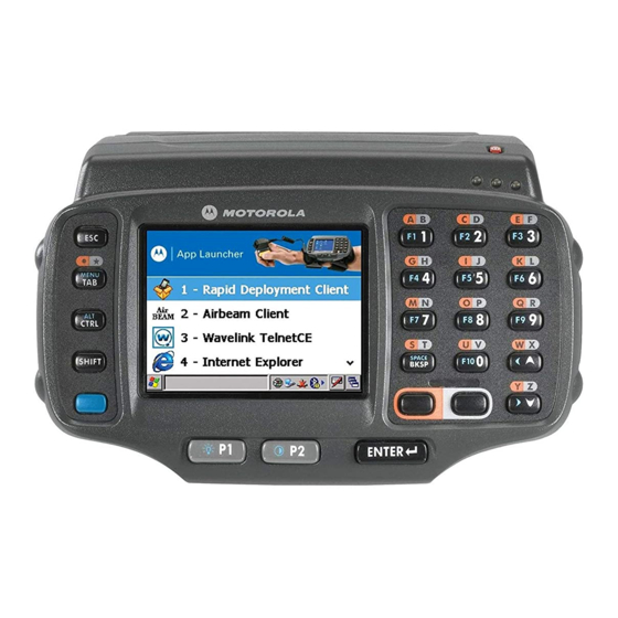
Page 36: Keypads
2 - 4 WT41N0 User Guide Keypads The wearable terminal has the following keypads: • Two-color alphanumeric keypad • Voice Only keypad. Two-color Alphanumeric Keypad The two-color alphanumeric keypad contains application keys, scroll keys and function keys. The keypad is color-coded to indicate the alternate function keys (blue, orange and gray). - Page 37 Using the Wearable Terminal 2 - 5 Two-color Alphanumeric Keypad Descriptions (Continued) Table 2-3 Description Scroll Keys Moves up or down from one item to another or increases/decreases specified values. Moves left or right from one item to another when used with the Blue key. For each left or right scroll, the Blue key must be pressed first.
- Page 38 2 - 6 WT41N0 User Guide Special Character Generation Map (Continued) Table 2-4 Special Character Two-color Keypad Triple-tap Keypad Blue - Orange - Blue - Orange - (period) Orange - Blue - Orange - 8 Blue - Orange - 8 (semi-colon) Blue - Orange - 9 Blue - Orange - 9...
-
Page 39: Voice Only Keypad
Using the Wearable Terminal 2 - 7 Special Character Generation Map (Continued) Table 2-4 Special Character Two-color Keypad Triple-tap Keypad Shift - Blue - Orange - 4 Shift - Blue - Orange - 4 (pipe) Shift - Blue - Orange - 5 Shift - Blue - Orange - 5 (tilde) <... -
Page 40: Display
2 - 8 WT41N0 User Guide Display To view the software versions on the Voice Only WT41N0, the Voice Only WT41N0 must be NOTE connected to a host computer running remote desktop software. See the WT41N0 Integrator Guide for more information. The wearable terminal is factory installed with the Windows CE 7.0 operating system. -
Page 41: Windows Ce 7.0 Desktop
Using the Wearable Terminal 2 - 9 Windows CE 7.0 Desktop The following paragraphs describe the Windows CE 7.0 desktop. Depending upon the customer’s configuration of the wearable terminal, the desktop may not be available. Status Icons The Taskbar at the bottom of the window displays the active programs, current time, battery status and communication status. -
Page 42: Programs Menu
Indicates that the Orange key is selected. Indicates that the Gray key is selected. Indicates that the Motorola Remote Control software is connected to the wearable terminal. Programs Menu NOTE For the non-touch configurations, see ????? for instruction on navigating using the navigation pad. -
Page 43: Troubleshooting
Using the Wearable Terminal 2 - 11 Applications in the Programs Menu Table 2-7 Icon Description Icon Description AppLauncher: Fusion Folder: Open the Wireless Companion folder. See Chapter 5, Wireless Applications for more BTScannerCtlPanel: information. Internet Explorer Microsoft WordPad MotoBTUI Command Prompt: Opens a DOS CtlPanel: View and change wearable command prompt window. -
Page 44: Control Panel
2 - 12 WT41N0 User Guide Control Panel Table 2-8 lists the applications in the Control Panel. Programs on the Control Panel Table 2-8 Icon Description Icon Description Backlight: Adjust the backlight Bluetooth Device Properties: Launch brightness and power settings. the Bluetooth application. -
Page 45: Using The Keypad To Navigate Applications
Using the Wearable Terminal 2 - 13 Using the Keypad to Navigate Applications NOTE Not available on the Voice Only configuration. On wearable computers without touch-enabled screens navigation and control of an application is performed using the keypad. Key Combinations The wearable terminal uses special key combinations to easily navigate applications. -
Page 46: Navigating Menus
2 - 14 WT41N0 User Guide Highlighted Item Highlighted Items Figure 2-8 Navigating Menus Most applications have drop-down menus to perform specific functions. Use the key combination open a menu. Once the menu is open, use the up and down navigation keys to move up and down the menu and use the left and right navigation keys to move to the next menu item or open a sub-menu. -
Page 47: Selecting Checkboxes And Radio Buttons
Using the Wearable Terminal 2 - 15 Selecting Checkboxes and Radio Buttons To select or deselect checkboxes and radio buttons press the TAB key until the field is highlighted. Press (SPACE) to select or deselect the checkbox or radio button. BKSP Highlighted Checkbox Radio Buttons... -
Page 48: Special Character Keypad
2 - 16 WT41N0 User Guide Calibration Screen Confirm Calibration Screen Calibration Screen Figure 2-12 Once all of the new calibration settings are input, tap the screen or press the button to save the ENTER new calibration settings. Press to discard the new calibration settings. Special Character Keypad NOTE The Special Character Keypad is only available on non-touch screen configurations with a display. -
Page 49: Resetting The Wearable Terminal
Using the Wearable Terminal 2 - 17 Special Character Keyboard - Character Layer Figure 2-14 Navigate the keypad in the same manner as described above. To return to the alphanumeric layer, press the CH key on the keypad. Pressing CAP or SH switches the keypad to the upper case alphanumeric keypad. Special Character Keyboard in upper case Alphanumeric Mode Figure 2-15 Press the... -
Page 50: Performing A Cold Boot
2 - 18 WT41N0 User Guide Performing a Cold Boot A cold boot restarts the wearable terminal and erases all user stored records and entries that are not saved in flash memory (Application and Platform folders). Never perform a cold boot unless a warm boot does not solve the problem. -
Page 51: Waking The Wearable Terminal
Using the Wearable Terminal 2 - 19 Waking the Wearable Terminal The wake up conditions define what actions wake up the wearable terminal after it has gone into suspend mode. The wearable terminal can go into suspend mode by either pressing the Power button or automatically by control panel time-out settings. - Page 52 2 - 20 WT41N0 User Guide...
-
Page 53: Chapter 3 Data Capture
CHAPTER 3 DATA CAPTURE Introduction The wearable terminal can be used with the following optional data capture accessories: • RS309 laser scanner • RS409 laser scanner • RS419 laser scanner • RS507 Hands-free imager. Laser Scanning Wearable terminals with an optional RS309, RS409 or RS419 laser scanner have the following features: •... -
Page 54: Scanning Bar Codes
3 - 2 WT41N0 User Guide Scanning angle is important for promoting quick decodes. When laser beams reflect directly back into the scanner from the bar code, this specular reflection can “blind” the scanner. To avoid this, scan the bar code so that the beam does not bounce directly back. But don’t scan at too sharp an angle;... -
Page 55: Imaging
The imager remains in this mode as long as you hold the scan button, or until it decodes a bar code. NOTE To enable Pick List Mode, download the Control Panel applet from the Support Central web site at http://www.motorola.com/enterprisemobility/support. Pick List can also be set in an application using a API command. •... - Page 56 3 - 4 WT41N0 User Guide Imager Aiming Pattern Figure 3-2 Pick List Mode with Multiple Bar Codes Figure 3-3 Release the scan button. NOTE Imager decoding usually occurs instantaneously. The RS507 repeats the steps required to take a digital picture (image) of a poor or difficult bar code as long as the scan button remains pressed.
-
Page 57: Chapter 4 Wireless Applications
Refer to the Wireless Fusion Enterprise Mobility Suite User Guide for Version X1.01 for information on configuring wireless profiles. Go to http://supportcentral.motorola.com for the latest version of this guide. See Software Versions on page x to determine the Fusion version on the wearable terminal. -
Page 58: Signal Strength Icon
4 - 2 WT41N0 User Guide Many of the items in the menu invoke one of the Fusion applications. These menu items and their corresponding applications are summarized in Table 4-1. Supported Applications Table 4-1 Application Description Find WLANs Invokes the Find WLANs application which displays a list of the WLANs available in your area. -
Page 59: Turning Off The Radio
Wireless Applications 4 - 3 Signal Strength Icons Descriptions (Continued) Table 4-2 Icon Status Action Fair signal strength WLAN network is ready to use. Notify the network administrator that the signal strength is only “Fair”. Poor signal strength WLAN network is ready to use. Performance may not be optimum. - Page 60 4 - 4 WT41N0 User Guide...
Need help?
Do you have a question about the WT41NO and is the answer not in the manual?
Questions and answers