Table of Contents
Advertisement
Quick Links
Advertisement
Table of Contents

Related Manuals for Panasonic AU-EVA1E


Summary of Contents for Panasonic AU-EVA1E
-
Page 1: Operating Instructions
Operating Instructions Memory Card Camera-Recorder AU-EVA1E Model No. Before using this product, be sure to read “Read this first!” (pages 2 to 5). Before operating this product, please read the instructions carefully and save this manual for future use. ENGLISH... -
Page 2: Read This First
Read this first! Read this first! indicates safety information. WARNING: CAUTION: • To reduce the risk of fire or electric shock, do To reduce the risk of fire or electric shock and annoying not expose this equipment to rain or moisture. interference, use the recommended accessories only. -
Page 3: Caution For Ac Mains Lead
AEEE Complies with Directive of Turkey. The rating plate is on the underside of the Camera Recorder, Battery Charger and AC Adaptor. Manufactured by: Panasonic Corporation, Osaka, Japan Importer’s name and address of pursuant to EU rules: Panasonic Marketing Europe GmbH... - Page 4 Batteries that may be used with this product (Correct as of October 2017) Panasonic AG-VBR59 / AG-VBR89 / AG-VBR118 / VW-VBD58 batteries may be used with this product. Note regarding the Power Management function specified under COMMISSION REGULATION (EC) No 1275/2008 implementing Directive 2009/125/EC of the European Parliament and of the Council.
-
Page 5: To Remove The Battery
Read this first! To remove the battery Main Power Battery (Lithium ion Battery) (Refer to page 29 for the detail.) Press the battery release button. Battery release button Back-up Battery (Lithium Battery) • For the removal of the battery for disposal at the end of its service life, please consult your dealer. Battery Charger / AC Adaptor Disconnect the AC mains plug from the AC mains socket when not in use. - Page 6 SDXC logo is a trademark of SD-3C, LLC. f AVCHD, AVCHD Progressive, and AVCHD Progressive logo are trademarks of Panasonic Corporation and Sony Corporation. f This is manufactured based on license from Dolby Laboratories, Inc. Dolby, Dolby Audio, and the double-D symbol are trademarks of Dolby Laboratories.
-
Page 7: Table Of Contents
Contents Contents Read this first! Displaying the menu Operating the menu Chapter 1 Overview Initializing the menu Menu setting contents Before using the camera [THUMBNAIL] menu Accessories [SYSTEM SETTINGS] menu Use of the camera on a system [CAMERA SETTINGS] menu Basic configuration devices [SCENE FILE SETTINGS] menu [REC SETTINGS] menu... - Page 8 Contents Copying clips Deleting clips Protecting clips Restoring clips Playing back clips Useful playback function Resume play Chapter 7 Output and Screen Display Output format Format that can be output from the <SDI OUT> terminal Format that can be output from the <HDMI> terminal Screen status display Chapter 8 Connecting to External Devices...
-
Page 9: Chapter 1 Overview
Overview Chapter 1 Before using the camera, read this chapter. -
Page 10: Before Using The Camera
Chapter 1 Overview — Before using the camera Before using the camera r Before using the camera, always check if the built-in battery is not consumed, and then set the date/time. The internal clock of the camera is reset when the built-in battery has been consumed. This may result in the meta data of the clip not recorded correctly, and it may not display correctly in the thumbnail screen. - Page 11 Panasonic will not assume liability when video or audio recording fails due to a malfunction of the camera or the memory card during the use. f Set the calendar (datetime of the internal clock) and the time zone, or check the setting before recording. This will have an effect on the management of the recorded contents.
- Page 12 Do not install in a location where the camera, cable, etc., can be easily damaged. r Security Take caution so the camera is not stolen, lost, or neglected. Note that Panasonic is not liable to leakage, falsification, or loss of information caused by them.
-
Page 13: Accessories
Chapter 1 Overview — Accessories Accessories Battery (Parts No.: AG-VBR59) (page 27) Grip (page 32) f Already mounted to the camera. Battery charger (Parts No.: AG-BRD50) (page 27) Grip belt (page 32) f Already mounted to the grip. AC adaptor (page 27) LCD monitor (page 35) AC cable (x 2) (page 27) f For AC adaptor... -
Page 14: Use Of The Camera On A System
“Preparing the SD card” * For the latest information not included in these Operating Instructions, refer to the support desk at the following website. http://pro-av.panasonic.net/ Expanded configuration devices In addition to the basic components, a wireless module can be used. -
Page 15: What You Can Do With This Camera
Connecting to monitor A monitor can be connected to output images. f Use the double shielded cable supporting 4K/60P as the HDMI cable (optional). It is also recommended to use the Panasonic 4K/60P compatible HDMI cable. f For the BNC cable (optional) connected to the <SDI OUT> terminal, prepare a double-shielded cable equivalent to 5C-FB. -
Page 16: Chapter 2 Description Of Parts
Description of Parts Chapter 2 This chapter describes the names, functions, and operations of parts on the camera. -
Page 17: Camera
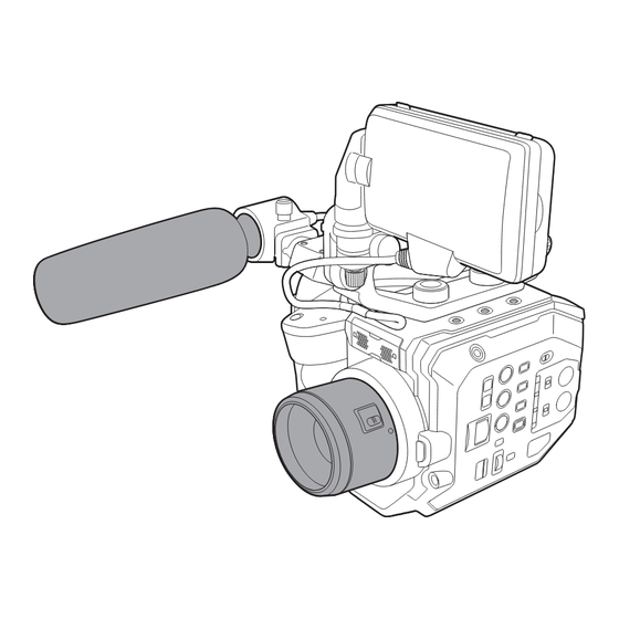
Chapter 2 Description of Parts — Camera Camera Left side Following terminal is inside the cover. f <LCD> terminal 1 Accessory mounting section The included LCD monitor mounting attachment can also be mounted. 2 HDMI cable clamp Fixes the HDMI cable. 3 Microphone cable clamp Fixes the external microphone cable. -
Page 18: Right Side
Chapter 2 Description of Parts — Camera Right side 20 21 1 LCD monitor unit mounting section Mounts the included LCD monitor mounting attachment. 2 Handle This is a removable handle. Already mounted to the camera. 3 REC button Starts or stops the recording. 4 <ND FILTER>... -
Page 19: Front Side
Chapter 2 Description of Parts — Camera 14 Built-in speaker Outputs audio during playback. Audio is not output from the built-in speaker when headphones are connected to the headphone terminal. 15 USER buttons (<USER 1>, <USER 2>/<VIEW>, <USER 3>/<INFO>) A function selected by the user can be assigned to each button. Pressing the button while the VIEW screen is displayed will perform the assigned function. -
Page 20: Rear Side
Chapter 2 Description of Parts — Camera 4 EF lens mount EF lens is mounted. f The figure shows the status when the mount cap is attached. Remove the mount cap when the lens is to be mounted. 5 Lens lock unlock button The lock is unlocked when the lens is to be removed from the camera. -
Page 21: Top Side
Chapter 2 Description of Parts — Camera 10 <SERVICE> terminal A maintenance terminal. 11 Battery release button Used when removing the battery from the camera. 12 Headphone terminal Connects audio monitoring headphones. 13 <SDI OUT> terminal A terminal to output SDI signal by connecting a monitor, etc. 14 Fan outlet Fan outlet for cooling fan. -
Page 22: Bottom Side
Chapter 2 Description of Parts — Camera Bottom side 1 Tripod holes Attach the tripod. f Mounting hole size - 1/4-20 UNC (screw length 5.5 mm or shorter) - 3/8-16 UNC (screw length 5.5 mm or shorter) – 22 –... -
Page 23: Lcd Monitor Unit
Chapter 2 Description of Parts — LCD monitor unit LCD monitor unit 1 LCD monitor hood Blocks the light from outside, making it easier to view the LCD monitor. 2 LCD monitor Displays the screen to set the basic setting of the camera and check the status of the camera. In addition to the HOME screen that is the starting point of the operation, the VIEW screen that displays the recording image, the INFO screen that displays the information of the camera, etc., can be displayed. -
Page 24: Grip
Chapter 2 Description of Parts — Grip Grip The grip is already mounted to the camera. 1 <EXIT>/<USER 8> button Returns to one level higher from the current menu when the menu is displayed. Pressing the <EXIT> button without confirming the setting value will not reflect the change in the setting. -
Page 25: Basic Operation
Chapter 2 Description of Parts — Basic operation Basic operation Multidial operation Operate the multidial on the camera by turning it in vertical direction or pushing it. f Turning the multidial in vertical direction will move the cursor. f Pressing the multidial will select or confirm the item with cursor. NOTE t For details on menu operation method, refer to “When operating with the multidial”. -
Page 26: Chapter 3 Preparation
Preparation Chapter 3 Before you use the camera, mount the battery following the procedures in this chapter. The mounting of accessories is also described in this chapter. -
Page 27: Power Supply
Chapter 3 Preparation — Power supply Power supply A battery or the supplied AC adaptor can be used as the power supply for the camera. f The camera is compatible to following batteries. (As of October 2017) - AG-VBR59 (supplied/optional, supports quick charging) - AG-VBR89 (optional, supports quick charging) - AG-VBR118 (optional, supports quick charging) - VW-VBD58 (optional) - Page 28 Chapter 3 Preparation — Power supply Standard charging time and recording time Battery parts number Voltage/capacity (minimum) Charging time Continuous shootable time AG-VBR59 (supplied/optional) 7.28 V/5900 mAh Approx. 3 hours 20 minutes Approx. 2 hours 50 minutes AG-VBR89 (optional) 7.28 V/8850 mAh Approx.
-
Page 29: Attaching And Removing The Battery
Chapter 3 Preparation — Power supply Attaching and removing the battery Attaching the battery Press the battery against the battery mounting section of the camera, and mount it by sliding it downward. f Press in the battery until it clicks and gets locked. Removing the battery Battery release button Set the power switch to <... -
Page 30: Using The Ac Adaptor
Chapter 3 Preparation — Power supply Using the AC adaptor Attaching the AC adaptor Use the supplied AC adaptor. Do not use an AC adaptor for other device. The supplied AC cable is dedicated for this camera. Do not use with any other device. Also, do not use AC cable from other device on this camera. To the power outlet Fig. -
Page 31: Mounting Accessories
Chapter 3 Preparation — Mounting accessories Mounting accessories Handle The handle is already mounted to the camera. Mounting the handle Mount the handle to the accessory mounting holes at the top of the camera body using the handle mounting screws (x 2). NOTE t Use the handle after securely tightening the handle mounting screws (x 2). -
Page 32: Grip
Chapter 3 Preparation — Mounting accessories Grip The grip is already mounted to the camera. Mounting the grip Mount reference points Fig. 1 Fig. 2 Grip cable clamp <REMOTE> terminal Grip cable Fig. 3 Insert the grip to the camera. (Fig. 1) f Align the mount reference points on the grip mounting section of the camera and the grip mounting section of the grip when inserting into the camera. -
Page 33: Mounting Accessories
Chapter 3 Preparation — Mounting accessories r Adjusting the angle of the grip Grip rotation lever Pull the grip rotation lever to the <UNLOCK> side. Adjust the angle of the grip, and return the grip rotation lever at the position to fix. The grip is fixed. -
Page 34: Mounting Accessories
Chapter 3 Preparation — Mounting accessories Removing the grip <GRIP RELEASE> button Remove the grip cable from the grip cable clamp. Remove the grip cable from the <REMOTE> terminal. While pressing the <GRIP RELEASE> button on the camera, turn the grip clockwise. NOTE t Remove the grip after placing the camera body on a level location, such as desk. -
Page 35: Lcd Monitor Unit
Chapter 3 Preparation — Mounting accessories LCD monitor unit Mounting the LCD monitor unit Mount the supplied LCD monitor unit to the LCD monitor mounting section. Screw Fig. 1 Fig. 2 Fig. 3 Insert the supplied LCD monitor mounting attachment to the LCD monitor unit mounting section of the handle. (Fig. 1) f This can also be mounted to the accessory mounting holes at the top of the camera. -
Page 36: Mounting Accessories
Chapter 3 Preparation — Mounting accessories Removing the LCD monitor unit Remove in the reverse procedure as mounting. NOTE t To disconnect the LCD monitor unit cable, pull out while pressing on the lock buttons on both sides of the cable connection terminal (s). LCD monitor hood The LCD monitor hood is already mounted to the LCD monitor unit. -
Page 37: Attaching The Shoulder Strap
Chapter 3 Preparation — Mounting accessories Mounting the LCD monitor hood Align the tabs at the top of the LCD monitor hood (2 locations) to the dimples at the top of the LCD monitor unit. Align the tabs at the bottom of the LCD monitor hood (2 locations) to the dimples at the bottom of the LCD monitor unit. Attaching the shoulder strap Mount the supplied shoulder strap to the shoulder strap mounting section. -
Page 38: Mounting The External Microphone
Chapter 3 Preparation — Mounting accessories Mounting the external microphone External microphone such as the super-directional microphone AG-MC200G (optional) can be mounted onto the handle. Microphone holder adaptor Microphone holder Screw for the microphone holder Fig. 1 Fig. 2 Screw Microphone cable clamp <AUDIO INPUT 1>... -
Page 39: Mounting The Lens
Chapter 3 Preparation — Mounting accessories Mounting the lens Mount/remove the lens in a location away from direct sunlight or intense lighting. Take care not to drop the camera or the lens. Prevent dirt or dust from entering into the EF lens mount. Mount cap Mark Fig. -
Page 40: Attaching A Tripod
Chapter 3 Preparation — Mounting accessories f Mount the mount cap turning in clockwise direction with the mark on the mount cap at the top. NOTE t Do not touch the EF lens mount and inside the EF lens mount. t Attach the mount cap to the EF lens mount. -
Page 41: Turning On/Off The Power
Chapter 3 Preparation — Turning on/off the power Turning on/off the power Power switch How to turn on the power Set the power switch to <l> (ON). The power lamp will illuminate in red when the power is on. f The [TIME ZONE] screen, and then the [CLOCK SETTING] screen are displayed in sequence when the power is turned on for the first time. Set the time zone, date, and time. -
Page 42: Charging The Built-In Battery
Chapter 3 Preparation — Charging the built-in battery Charging the built-in battery The date/time set in the camera is maintained by the built-in battery. The built-in battery may exhaust when the camera is not turned on for approximately two months. The built-in battery is exhausted when [BACKUP BATT EMPTY] is displayed on the LCD monitor when the power switch is set to <l>... -
Page 43: Setting The Date/Time Of The Internal Clock
Chapter 3 Preparation — Setting the date/time of the internal clock Setting the date/time of the internal clock The date/time/time zone are recorded as meta data in the clip while shooting. It will affect the management of the recorded contents, so always check and set the date/time and time zone before using the camera for the first time. Do not change the setting of the date/time and time zone while shooting. -
Page 44: Preparing The Sd Card
48 GB - 128 GB f Operation is not guaranteed for any SD cards other than above. f It is recommended to use the Panasonic SD card. f Following SD cards cannot be used since they are not compliant with the SD standards. -
Page 45: Inserting/Removing Of The Sd Card
Chapter 3 Preparation — Preparing the SD card Card access lamp SD card status No remaining recordable capacity There is no more SD card recording capacity. Only reading is possible. Write-protected The lock switch of the SD card is set to the LOCK side. Green (slowly flashing) It cannot record with the recording format that is currently set. -
Page 46: Formatting The Sd Card
Chapter 3 Preparation — Preparing the SD card Formatting the SD card Select the [REC SETTINGS] menu → [CARDS/MEDIA] → [FORMAT MEDIA] → [SLOT1]/[SLOT2]. When the confirmation message is displayed, select [SET]. When the completion message is displayed, select NOTE t This function can be operated also by touching the LCD monitor. -
Page 47: Handling Of The Recording Data
Chapter 3 Preparation — Preparing the SD card t The recording is stopped once when the recording time reaches ten hours, and recording is automatically resumed after few seconds. Image and audio during the pause will not be recorded. This includes the case of special recording, such as relay recording. t Protection by DVD recorders will be automatically removed from SD cards that are AVCHD protected. - Page 48 Video format: Progressive recording (MOV, LPCM) File name of the MOV format video data The file name format is the same as Panasonic VARICAM series (AU-V35LT1G, etc) CINE format. Clip can be managed in the same manner as VARICAM.
-
Page 49: Setting Of Time Data
Use with this setting when using the frame rate information of the user bits with an editing device such as a PC. Use this setting to control the recording operation in TYPE1 or TYPE2 method against the Panasonic recorder (AJ-PG50, etc.). -
Page 50: Setting The Time Code
Chapter 3 Preparation — Setting of time data Memory function of the user bits Setting contents of the user bits is automatically recorded, and it is maintained even if the power is set to < > (standby). Frame rate information The relationship between frame rate, image pull-down, time code, and user bits is as follows. -
Page 51: Presetting The Time Code To External
Chapter 3 Preparation — Setting of time data Time code with variable frame rate record The time code is fixed to [REC RUN] when the variable frame rate recording function is set to enable. The time code will advance in the speed corresponding to the ratio setting values of [FREQUENCY] (system frequency) and [FPS] (frame rate). -
Page 52: Supplying The Time Code Externally
Chapter 3 Preparation — Setting of time data Supplying the time code externally The time code output from the camera corresponding to the camera video or the playback video can be supplied to an external recording device. <SDI OUT> terminal SDI IN terminal VTR, etc. -
Page 53: Assigning Function To The User Buttons
Chapter 3 Preparation — Assigning function to the USER buttons Assigning function to the USER buttons Selected function can be assigned to the USER buttons. f The buttons that can be used as a USER button are as follows. - <USER 1> to <USER 9> buttons These can be used as the USER buttons when the VIEW screen is displayed. -
Page 54: Checking The Function Assigned To The User Buttons
Chapter 3 Preparation — Assigning function to the USER buttons NOTE t Following functions will be disabled when the camera is set to < > (standby) and then turned on again. [ATW LOCK], [D.ZOOM], [EXPAND], [PEAK./SQUARES F.A.], [WFM], [SPOT METER], [LCD CLEAN VIEW], [COLOR BARS], [POWER LCD] t Following functions will be enabled when the camera is set to <... -
Page 55: Tally Lamp
Chapter 3 Preparation — Tally lamp Tally lamp The front tally lamp and the rear tally lamp can be illuminated during the shooting. Select the [SYSTEM SETTINGS] menu → [LED & FAN] → [TALLY LED] → [FRONT]/[REAR]/[BOTH]. f The tally lamp will flash when the camera is in the following status. - When the remaining capacity of the SD card or the remaining battery level is low (one time per second) - The SD card has no more space to record (four times per second) - When a warning such as a system error or a recording abnormality has occurred (four times per second) -
Page 56: Chapter 4 Operation
Operation Chapter 4 This chapter describes how to operate the screen of this camera, how to operate the menu, the structure of the menu, and details of the menu. -
Page 57: Basic Operation Of The Screen
Chapter 4 Operation — Basic operation of the screen Basic operation of the screen Major button operation and screen display 1 <VIEW> button 2 <INFO> button 3 <THUMBNAIL> button 4 <HOME> button r <VIEW> button Displays the VIEW screen. Displays the shooting screen. The VIEW screen is displayed when the camera is turned on. -
Page 58: Major Button Operation And Switching Screen
Chapter 4 Operation — Basic operation of the screen Major button operation and switching screen Switches the screen as follows when the <HOME> button, <INFO> button, <VIEW> button, or <THUMBNAIL> button is pressed. Thumbnail screen HOME screen VIEW screen Clip information INFO screen 1 <HOME>... -
Page 59: Displaying The Home Screen
Chapter 4 Operation — Displaying the HOME screen Displaying the HOME screen Status of the camera can be confirmed. 1 [FPS] Displays the setting status of the variable frame rate recording function and the recording frame rate. 2 [COLOR] Displays the color setting of the video recorded to the main recorder. 3 [SHUTTER] Displays the shutter speed. -
Page 60: Displaying The Home Screen
Chapter 4 Operation — Displaying the HOME screen 12 Power status display Displays the remaining battery level, or the drive status of the AC adaptor. : Driving with the battery (remaining battery level) : Driving with the AC adaptor 13 Main recording codec Displays the recording codec of the main recorder. -
Page 61: Operating Each Screen
Chapter 4 Operation — Operating each screen Operating each screen The HOME screen, which is the starting point of screen operation is displayed by pressing the <HOME> button. Display the HOME screen, select [FPS], [COLOR], [SHUTTER], [EI], [AUDIO], or [WB], and change the value, etc., in the displayed screen. f There is a method to operate with the multidial or a grip multidial, or a method to operate by touching the LCD monitor. -
Page 62: Operating Each Screen
Chapter 4 Operation — Operating each screen [COLOR] When [COLOR] is selected in the HOME screen, the COLOR screen is displayed allowing to set the color of the image (gamma and gamut). [MAIN COLOR]: Sets the color of video recorded in the main recorder (entire camera system). [SDI OUT]: Sets the output image from the <SDI OUT>... -
Page 63: Info Screen
Chapter 4 Operation — Operating each screen [WB] When [WB] is selected in the HOME screen, the VIEW screen is displayed, allowing to set the color temperature (white balance). f Select from the previously registered white balance setting values in [`]/[{]. f The white balance setting value can be added/deleted in the [CAMERA SETTINGS] menu →... -
Page 64: Basic Operation Of The Menu
Chapter 4 Operation — Basic operation of the menu Basic operation of the menu The setting of the camera can be changed with the menu in accordance to the shooting scene or recording contents. Set data is written and saved in the camera memory. f There is a method to operate with the multidial or a grip multidial, or a method to operate by touching the LCD monitor. -
Page 65: Displaying The Menu
Chapter 4 Operation — Basic operation of the menu Displaying the menu Displays the menu, and select the menu or item to set. Press the <MENU> button when not recording. The menu is displayed. 1 Level display Displays the path of the menu to the currently displayed screen. 2 [`]/[{] Moves the cursor up or down when selected. -
Page 66: Operating The Menu
Chapter 4 Operation — Basic operation of the menu Operating the menu Various settings are possible from the menu. There are two methods of operation, a method to operate with the multidial or grip multidial, or a method to touch the LCD monitor. When operating with the multidial Operate the multidial on the camera by turning it in vertical direction or pushing it. -
Page 67: Initializing The Menu
Chapter 4 Operation — Basic operation of the menu When operating by touching the LCD monitor Operate by touching the LCD monitor. Press the <MENU> button when not recording. The menu is displayed. f VIEW menu screen is also displayed by touching the LCD monitor for one second or more and releasing while the screen is displayed. Select the menu to set. -
Page 68: Menu Setting Contents
Chapter 4 Operation — Menu setting contents Menu setting contents [THUMBNAIL] menu Performs confirmation or deleting of the recording clip. This menu can be set when the thumbnail screen is displayed. [PLAYBACK] [SLOT SEL] Selects a clip to be displayed on the thumbnail screen. [ALL SLOT] Displays the clips recorded on all the SD cards in each card slot. - Page 69 Chapter 4 Operation — Menu setting contents NOTE t When the [SYSTEM SETTINGS] menu → [SENSOR MODE] → [4/3 CROP&MIX 2.2K] is set - The sensitivity will be lower than when [S35 5.7K] or [S35 MIX 2.8K] is set. - [400 ISO] or [1250 ISO] can be set in the [SYSTEM SETTINGS] menu → [EI] → [NATIVE ISO]. [MAIN PIXEL] Sets the main recorder’s number of recording pixels.
- Page 70 Chapter 4 Operation — Menu setting contents [V-709] Outputs by converting to a color comparable to the standard CINE-LIKE. This is the setting appropriate for preview. f When [MAIN] in [COLOR SETTINGS] is set to [SCENE1], [SCENE2], [SCENE3], [SCENE4], or [SCENE5] [SCENE1], [SCENE2], [SCENE3], Outputs with the same color as the video recorded in the main recorder.
- Page 71 Chapter 4 Operation — Menu setting contents [USER4] Sets if the <USER 4> button is to be locked or not with the <LOCK> switch. [LOCK] It will be locked. [UNLOCK] It will not be locked. (Factory setting: [LOCK]) [USER5] Sets if the <USER 5> button is to be locked or not with the <LOCK> switch. [LOCK] It will be locked.
- Page 72 Chapter 4 Operation — Menu setting contents [MULTI DIAL] Sets if the multidial is to be locked or not with the <LOCK> switch. [LOCK] It will be locked. [UNLOCK] It will not be locked. (Factory setting: [LOCK]) [LED & FAN] [TALLY LED] Sets if the tally lamp is to illuminate or not.
- Page 73 Chapter 4 Operation — Menu setting contents [CLOCK] [CLOCK SETTING] Sets the calendar (date of the built-in clock) and time. [YEAR] [2017]…[2037] [MONTH] [JAN]…[DEC] ([1]…[12]) [DAY] [1]…[31] ([28], [29], [30]) [HOUR] [0]…[23] [MINUTE] [0]…[59] (Factory setting: [YEAR]: [2017], [MONTH]: [1], [DAY]: [1], [HOUR]: [0], [MINUTE]: [0]) [TIME ZONE] Sets the time zone.
-
Page 74: [Camera Settings] Menu
Chapter 4 Operation — Menu setting contents [CAMERA SETTINGS] menu Sets the basic camera function. This menu cannot be set when the thumbnail screen is displayed. [FPS] [VFR SW] Enables/disables the variable frame rate recording function. [ON] Enables the variable frame rate recording function. The arbitrary frame rate can be set in [VALUE] of [FPS]. Audio cannot be recorded when [FREQUENCY] and [FPS] are different. - Page 75 Chapter 4 Operation — Menu setting contents [ADD sec] Newly registers the value of time to select when the display unit in [MODE] of [SHUTTER] is set to [sec]. The newly registered value can be selected in [VALUE sec]. Maximum of 12 values can be registered. It cannot be registered when there are 12 registered already. [EDIT sec] The currently selected setting value can be edited.
-
Page 76: Lens Settings
Chapter 4 Operation — Menu setting contents When [GAMMA SELECT] is set to [−12dB], [−10dB], [−8dB], [−6dB], [−4dB], [−2dB], [0dB], [2dB], [4dB], [6dB], [8dB] anything other than [VIDEO] When [GAMMA SELECT] is set [−8dB], [−6dB], [−4dB], [−2dB], [0dB], [2dB], [4dB], [6dB], [8dB], [10dB], [12dB], [14dB], [16dB], [18dB], [20dB] to [VIDEO] f When [HIGH] is selected in [GAIN MODE] When [GAMMA SELECT] is set to... -
Page 77: Auto Black Balance
For the latest information regarding the EF lens supporting the acquisition of the focal distance information with the communication between the camera and the lens, refer to the support desk at the following website. http://pro-av.panasonic.net/ [ZOOM POSITION VALUE] Sets the focal distance (mm) used when [ZOOM POSITION DATA] is set to [MANUAL]. -
Page 78: [Scene File Settings] Menu
Chapter 4 Operation — Menu setting contents [SCENE FILE SETTINGS] menu Sets the detailed image quality adjustment of the camera video. This menu cannot be set when the thumbnail screen is displayed. [NAME EDIT] Edits the name of the scene file selected in the [SYSTEM SETTINGS] menu → [COLOR SETTINGS] → [MAIN]. (Maximum eight characters) [SCENE DATA] For saving and loading target, refer to “Target items for scene file/setup file/initialization”. - Page 79 Chapter 4 Operation — Menu setting contents [HLG] A hybrid log gamma (HLG) curve. (Factory setting: [V-255570L1]) [MASTER GAMMA] Sets the master gamma in 0.01 steps. The items that can be set are as follows. f [0.30]…[0.75] (Factory setting: [0.45]) [BLACK GAMMA] Sets the gamma curves of dark areas.
- Page 80 Chapter 4 Operation — Menu setting contents [KNEE POINT] Sets the position of the knee point for HLG. The items that can be set are as follows. f [55%]…[109%] (1% steps) (Factory setting: [55%]) [KNEE SLOPE] Sets the inclination of knee for HLG. The items that can be set are as follows.
-
Page 81: Color Correction
Chapter 4 Operation — Menu setting contents The items that can be set are as follows. f [ON], [OFF] (Factory setting: [OFF]) [CHROMA] [LEVEL] Sets the chroma level of P and P signals. The items that can be set are as follows. f [OFF], [−99%]…[99%] (Factory setting: [0%]) [MATRIX]... -
Page 82: [Rec Settings] Menu
Chapter 4 Operation — Menu setting contents [REC SETTINGS] menu Sets the various items in the recording function. [CARDS/MEDIA] [FORMAT MEDIA] Formats the SD card in the specified slot. Data deleted as a result of formatting cannot be restored. Always confirm the data before formatting. The items that can be selected are as follows. - Page 83 Chapter 4 Operation — Menu setting contents Minute [00]…[59] Second [00]…[59] Frame [00] … [23] (when [24.00p] or [23.98p] is set) [00] … [24] (when [50.00i], [50.00p], or [25.00p] is set) [00] … [29] (when [59.94i], [59.94p], or [29.97p] is set) (Factory setting: [00]) (each item) [SET UB] Sets user bits.
-
Page 84: [Audio Settings] Menu
Chapter 4 Operation — Menu setting contents [AUDIO SETTINGS] menu Sets the input/output function of audio. [AUDIO CH SETTINGS] [CH1 IN SELECT] Sets the audio to be recorded in the audio channel 1. [INT(L)] Records the audio from the built-in microphone <L>. [INPUT1] Records the input signal from the <AUDIO INPUT 1>... - Page 85 Chapter 4 Operation — Menu setting contents [INPUT1 MIC POWER] Enables/disables the phantom power supply for the external microphone connected to the <AUDIO INPUT 1> terminal. The items that can be set are as follows. f [ON], [OFF] (Factory setting: [OFF]) [INPUT2 MIC POWER] Enables/disables the phantom power supply for the external microphone connected to the <AUDIO INPUT 2>...
-
Page 86: [Output Settings] Menu
Chapter 4 Operation — Menu setting contents [START] The beep sound is generated only when the recording is started. [STOP] The beep sound is generated only when the recording is stopped. [START&STOP] The beep sound is generated when the recording is started and stopped. (Factory setting: [OFF]) [VOLUME] Sets the volume of the beep sound when starting or stopping the recording. -
Page 87: Hdmi Out
Chapter 4 Operation — Menu setting contents [3G-SDI OUT] Sets the format of the 3G SDI signal output from the <SDI OUT> terminal. Can be set when the 3G SDI signal is output. [LEVEL-A] Selects the LEVEL-A method. [LEVEL-B] Selects the LEVEL-B DL method. (Factory setting: [LEVEL-B]) [SDI REC REMOTE] Sets if the recording operation against the external equipment connected to the <SDI OUT>... - Page 88 Chapter 4 Operation — Menu setting contents [OFF] Does not control the recording operation of the external equipment. (Factory setting: [OFF]) [INDICATOR DISP] Displays/hides the item set in [SDI/HDMI INDICATOR] for the output from the <HDMI> terminal. [ON] Displays the shutter speed, remaining battery level, etc. Content of display follows the setting in [SDI/HDMI INDICATOR]. [OFF] Hides all.
- Page 89 Chapter 4 Operation — Menu setting contents The items that can be set are as follows. f [ON], [OFF] (Factory setting: [ON]) [TC] Displays/hides the time code, user bits, and duration counter. The display contents follow the setting in the [REC SETTINGS] menu → [TC] → [TC/UB/ Dur.].
- Page 90 Chapter 4 Operation — Menu setting contents (Factory setting: [ON]) [WLAN] Displays/hides the connection status display of the wireless LAN. The items that can be set are as follows. f [ON], [OFF] (Factory setting: [ON]) [IR SHOOTING] Displays/hides the setting in the [CAMERA SETTINGS] menu → [IR SHOOTING]. The items that can be set are as follows.
- Page 91 Chapter 4 Operation — Menu setting contents [LCD INDICATOR] Selects the indicator displayed in the LCD monitor. For details of the displayed contents, refer to “Screen status display”. [CLIP NAME] Displays/hides file name of the clip to record. Displays maximum of 8 characters from beginning. The items that can be set are as follows.
- Page 92 Chapter 4 Operation — Menu setting contents [FPS] Displays/hides the setting in the [CAMERA SETTINGS] menu → [FPS]. The items that can be set are as follows. f [ON], [OFF] (Factory setting: [ON]) [SHUTTER] Displays/hides the shutter speed. The items that can be set are as follows. f [ON], [OFF] (Factory setting: [ON]) [EI]...
- Page 93 Chapter 4 Operation — Menu setting contents [LCD MARKER] [CENTER MARKER] Switch the type of the center marker. + (large) Open center (large) + (small) Open center (small) [OFF] Does not display. (Factory setting: [1]) [SAFETY MARKER] Selects the type of frame for the safety zone marker. Corners [OFF] Does not display.
- Page 94 Chapter 4 Operation — Menu setting contents [PEAKING LEVEL] Sets the intensity of the peaking display. The items that can be set are as follows. f [LOW], [MID], [HIGH] (Factory setting: [MID]) [PEAKING COLOR] Sets the color of the peaking display. The items that can be set are as follows.
-
Page 95: [File] Menu
Chapter 4 Operation — Menu setting contents [SPOT METER UNIT] Sets the display unit for the spot meter. This is fixed to [%] when set to anything other than the [SYSTEM SETTINGS] menu → [COLOR SETTINGS] → [MAIN] → [V-Log]. The items that can be set are as follows. -
Page 96: [Network Settings] Menu
Chapter 4 Operation — Menu setting contents [NETWORK SETTINGS] menu Sets the setting regarding the network function. [NETWORK SEL] Sets if the external equipment (PC, etc.) and the camera is to be connected to the network using the wireless LAN. [WLAN] Connects with wireless LAN. - Page 97 Chapter 4 Operation — Menu setting contents [ENCRYPT KEY] Sets the encryption key. Set the key using a string of 8 to 63 characters or a hexadecimal number with 64 digits. (Factory setting: [01234567890123456789abcdef]) [DHCP] Sets if the automatic acquisition by DHCP is used or to use the DHCP function of the camera. [OFF] DHCP is not used.
-
Page 98: Factory Setting Value Of The Scene File
Chapter 4 Operation — Factory setting value of the scene file Factory setting value of the scene file [SCENE FILE SETTINGS] menu The factory setting values and items that can be selected in [SCENE FILE SETTINGS] differ depending on the [SYSTEM SETTINGS] menu → [COLOR SETTINGS] →... - Page 99 Chapter 4 Operation — Factory setting value of the scene file [MAIN] Item [SCENE1] [SCENE2] [SCENE3] [SCENE4] [SCENE5] [P2]([PHASE]) [P3]([SAT]) [P3]([PHASE]) [Yl]([SAT]) [Yl]([PHASE]) [P4]([SAT]) [P4]([PHASE]) [P5]([SAT]) [P5]([PHASE]) [G]([SAT]) [G]([PHASE]) [P6]([SAT]) [P6]([PHASE]) [Cy]([SAT]) [Cy]([PHASE]) [P7]([SAT]) [P7]([PHASE]) [B]([SAT]) [B]([PHASE]) [P8]([SAT]) [P8]([PHASE]) [Mg]([SAT]) [Mg]([PHASE]) [P9]([SAT]) [P9]([PHASE])
-
Page 100: Target Items For Scene File/Setup File/Initialization
Chapter 4 Operation — Target items for scene file/setup file/initialization Target items for scene file/setup file/initialization f SCENE: Items saved in scene files. f SETUP: Items saved in setup files. f INITIALIZE: Items that are initialized with the [SYSTEM SETTINGS] menu → [INITIALIZE] → [LOAD FACTORY DATA]. f Meaning of the symbols used in the table are as follows. -
Page 101: [Camera Settings] Menu
Chapter 4 Operation — Target items for scene file/setup file/initialization Item SCENE SETUP INITIALIZE [CLOCK] [CLOCK SETTING] — — — [TIME ZONE] — — — [DATE FORMAT] — [INFORMATION] [VERSION] — — — [OPERATION TIME] — — — [SENSOR TEMP] —... -
Page 102: [Rec Settings] Menu
Chapter 4 Operation — Target items for scene file/setup file/initialization Item SCENE SETUP INITIALIZE [BLACK] [M.PED] — [R PED] — [G PED] — [B PED] — [PEDESTAL OFFSET] — [GAMMA] [GAMMA SELECT] — [MASTER GAMMA] — [BLACK GAMMA] — [B.GAMMA RANGE] —... -
Page 103: [Output Settings] Menu
Chapter 4 Operation — Target items for scene file/setup file/initialization Item SCENE SETUP INITIALIZE [CH1 LIMITER] — [CH2 LIMITER] — [HEAD ROOM] — [AUDIO INPUT] [INPUT1 LINE/MIC SEL] — [INPUT2 LINE/MIC SEL] — [INPUT1 MIC POWER] — [INPUT2 MIC POWER] —... -
Page 104: [File] Menu
Chapter 4 Operation — Target items for scene file/setup file/initialization Item SCENE SETUP INITIALIZE [FRAME MARKER] — [FRAME COLOR] — [PLAYBACK MARKER] — [LCD INDICATOR] [CLIP NAME] — [PIXEL/FREQ] — [MAIN COLOR] — [REC FORMAT] — [SLOT1/2 STATUS] — [2 SLOTS FUNC.] —... -
Page 105: [Network Settings] Menu
Chapter 4 Operation — Target items for scene file/setup file/initialization [NETWORK SETTINGS] menu Item SCENE SETUP INITIALIZE [NETWORK SEL] — [NETWORK FUNC] [USER ACCOUNT] — — [NETWORK PROPERTY] [MAC ADDRESS] — — — [TYPE] — [SSID] — [BAND] — [CHANNEL(2.4GHz)] —... -
Page 106: Handling Setting Data
Chapter 4 Operation — Handling setting data Handling setting data Scene files File structure of the setting data The scene files of [SCENE1] to [SCENE5] can be saved in the camera memory in accordance to the scene file number. What can be saved as a scene file is the setting contents of the [SCENE FILE SETTINGS] menu. Also, the current setting value of the scene files [SCENE1] to [SCENE5] can be saved as a file to the camera memory and the SD card, and that data can be read and used in the camera. -
Page 107: Setup File
Chapter 4 Operation — Handling setting data Saving the scene file as a new file in the SD card Saves the current setting value of the camera into the SD card in the card slot 1 as a new file by specifying the file name. Select the [FILE] menu →... - Page 108 Chapter 4 Operation — Handling setting data Reading the setup file Reads the setup file saved in the SD card in the card slot 1. Select the [FILE] menu → [SETUP FILE] → [LOAD]. The list of setup files stored in the specified folder in the SD card in the card slot 1 is displayed. Select the file name for the file to read.
-
Page 109: Chapter 5 Shooting
Shooting Chapter 5 This chapter describes the basic procedure for recording. This chapter also describes the special recording method. -
Page 110: Shooting
Chapter 5 Shooting — Shooting Shooting For shooting, use the following steps. 1 REC button (camera body) 2 REC button (grip) Set the video settings and the audio input. f Before shooting, the followings must be set or adjusted. - Image settings for the brightness function (iris, gain, shutter) and the white balance adjustment function, etc. - Audio input settings for audio recording. - Page 111 Chapter 5 Shooting — Shooting [SENSOR MODE] [MAIN PIXEL] [MAIN CODEC] [4/3 CROP&MIX 2.2K] [2048x1080] [420LongGOP 50M] 1fps - 240fps [1920x1080] [420LongGOP 50M] When [FREQUENCY] is set to [24.00p] [SENSOR MODE] [MAIN PIXEL] [MAIN CODEC] [S35 5.7K] [4096x2160] [420LongGOP 100M] 1fps - 60fps [422LongGOP 150M] 1fps - 30fps...
- Page 112 Chapter 5 Shooting — Shooting When [FREQUENCY] is set to [59.94p] [SENSOR MODE] [MAIN PIXEL] [MAIN CODEC] [S35 5.7K] [4096x2160] [420LongGOP 150M] 1fps - 60fps [3840x2160] [420LongGOP 150M] [2048x1080] [422LongGOP 100M] 1fps - 60fps [1920x1080] [422LongGOP 100M] [AVCHD PS] — [1280x720] [AVCHD PM] —...
-
Page 113: Image Quality Adjustment
Chapter 5 Shooting — Image quality adjustment Image quality adjustment The image quality of the video to be recorded can be adjusted in the camera when the [SYSTEM SETTINGS] menu → [COLOR SETTINGS] → [MAIN] → [SCENE1] to [SCENE5]is set. f Adjust the image quality in the [CAMERA SETTINGS] menu. -
Page 114: [Black]
Chapter 5 Shooting — Image quality adjustment f Required size of white pattern is as follows. 1/2 or more of the screen width 1/2 or more of the screen height f Keep bright spotlights out of the screen. f The white pattern must be placed at the center of the screen. Manually setting the color temperature (setting with [VALUE]) Can be selected from the up to 12 registered color temperatures (white balance). - Page 115 Chapter 5 Shooting — Image quality adjustment Output (%) -7.5 Input/Stop [V-Log] [V-255570L1] ([SCENE1]: EVA-LOOK) [V-504580L1] ([SCENE2]: EVA-LOOK) Output (%) [VIDEO] ([SCENE3]/[SCENE4]: BC-LOOK) [KNEE SW] = [ON] [KNEE POINT] = [85%] [KNEE SLOPE] = [100] Input/dynamic range (%) Output (-) -7.5 1200 Input/dynamic range (%)
-
Page 116: [Knee]
Chapter 5 Shooting — Image quality adjustment It is recommended to shoot at 40% to 55% for face tone. f [V-504580L1] This is the EVA-LOOK gamma curve with 14Stop latitude equivalent to [V-Log]. The rise is equivalent to approximately 5.0 times, and the gamma factor is 0.45, which means up to 80%. This is a setting focused on soft texture. -
Page 117: [Hlg Knee]
Chapter 5 Shooting — Image quality adjustment [KNEE MODE] (setting for knee operation mode) Select the [SCENE FILE SETTINGS] menu → [KNEE] → [KNEE SW] → [ON]. Select the [SCENE FILE SETTINGS] menu → [KNEE] → [KNEE MODE] → [D RANGE]/[PRESS]. [D RANGE]: Determines the dynamic range that can be represented by the [KNEE SLOPE] value. -
Page 118: [Skin Detail]
Chapter 5 Shooting — Image quality adjustment Set the [SCENE FILE SETTINGS] menu → [DETAIL] → [CORING]/[MASTER LEVEL]/[FREQUENCY]. [CORING]: Sets the level of signal (including noise) not to activate the detail effect. [MASTER LEVEL]: Sets the level of the detail effect of the whole part. [FREQUENCY]: Sets the thickness of the detail as a whole. -
Page 119: [Color Correction]
Chapter 5 Shooting — Image quality adjustment [COLOR CORRECTION] This function sets color saturation and phase. This affects individually against the 16 phases of the image. It can be set to individual color hue. (Yl-R)-R (Yl-R) Yl-(Yl-R) Yellow (G-Yl)-Yl (G-Yl) PHASE(+) Green SAT(-) -
Page 120: Variable Frame Rate (Vfr) Recording Function
Chapter 5 Shooting — Variable frame rate (VFR) recording function Variable frame rate (VFR) recording function It is possible to acquire smooth slow motion or quick motion vide by shooting with a different frame rate from the frame rate to play back. Variable frame rate (VFR) Allows the high-speed shooting from 1fps to maximum of 240fps. -
Page 121: Special Recording Function
Chapter 5 Shooting — Special recording function Special recording function Special recording such as pre-recording or relay recording is possible by setting the menu. Pre-recording Records the video and audio from specific time before the operation to start the recording. Operation to start recording Operation to stop recording (Time) -
Page 122: Simultaneous Recording
Chapter 5 Shooting — Special recording function t The recording is stopped once when the recording time of relay recording exceeds ten hours. The recording is automatically resumed after few seconds. t For recording limitation of the relay recording, refer to “Recording function that cannot be used simultaneously”. Simultaneous recording Insert SD cards into two card slots, and record the same video onto two SD cards. -
Page 123: Convenient Shooting Functions
Chapter 5 Shooting — Convenient shooting functions Convenient shooting functions Zebra patterns display The camera can display two types of zebra patterns to the output image from the <LCD> terminal. Select the [OUTPUT SETTINGS] menu → [LCD EI ASSIST] → [ZEBRA] → [ON]. f Factory setting: [OFF] Setting the detection level Set the [OUTPUT SETTINGS] menu →... -
Page 124: Displaying Frame Marker
Chapter 5 Shooting — Convenient shooting functions Setting the size of the frame. Select the size of the frame in the [OUTPUT SETTINGS] menu → [LCD MARKER] → [SAFETY AREA]. Displaying frame marker A frame marker can be displayed. From the [OUTPUT SETTINGS] menu → [LCD MARKER] → [FRAME MARKER], select the angle of view. f The frame marker is not displayed when [OFF] is selected. - Page 125 Chapter 5 Shooting — Convenient shooting functions r Using the enlarged display function Press the USER button that [EXPAND] is assigned. Press the USER button again to return to the normal display. Setting the mode for enlarged display function Select the mode for enlarged display function in the [OUTPUT SETTINGS] menu → [LCD FOCUS ASSIST] → [EXPAND MODE]. [10SEC]: Disables the enlarged display function after ten seconds have elapsed.
-
Page 126: Electronic Image Stabilization Function
Chapter 5 Shooting — Convenient shooting functions How to view the focus square display Adjust the focus so that the square size displayed in the area of the subject to be focused becomes the largest. When focused on the doll When the panel is focused NOTE t The peaking display/focus square display cannot be recorded. -
Page 127: Waveform Monitor Function
Chapter 5 Shooting — Convenient shooting functions Waveform monitor function Waveform of the image can be displayed. r Assigning [WFM] to the USER button Set this function so that the waveform monitor can be displayed/hidden with an arbitrary USER button. Select the [SYSTEM SETTINGS] menu →... -
Page 128: Color Bars
Chapter 5 Shooting — Convenient shooting functions NOTE t The display of level gauge cannot be recorded. t The level gauge is not displayed when the enlarged display function of the focus assist function is enabled, or when displaying the color bars. t The level gauge may not display correctly while moving the camera. -
Page 129: Audio Input
Chapter 5 Shooting — Audio input Audio input The camera can record two channels of audio. The audio to input to each channel can be switched to the built-in microphone, an external microphone, or a connected audio device. Switching the audio input r Audio recording format The audio recording format such as compression format varies depending on the recording mode. -
Page 130: Monitoring The Audio
Chapter 5 Shooting — Audio input Manual adjustment of the recording level Set the <CH1>/<CH2> switch to <MANU>. Adjust the recording level with the <AUDIO LEVEL CH1>/<AUDIO LEVEL CH2> dial. f When the input level of audio exceeds 0 dB, the level display exceeding 0 dB is displayed in red in the audio level meter in the HOME screen. This is indicating that the input volume is too high. -
Page 131: Confirming Audio Input Setting
Chapter 5 Shooting — Audio input Operate the multidial to adjust the audio level. Confirming audio input setting Setting of the audio input can be confirmed in the [AUDIO] screen. Press the <INFO> while the HOME screen is displayed. The INFO screen is displayed. Select [AUDIO]. -
Page 132: Chapter 6 Playback
Playback Chapter 6 Data including additional information such as image, audio, and meta data that are recorded by single shooting is saved as a clip. Playback, copy, etc., of the clip can be performed on the camera. -
Page 133: Thumbnail Operation
Chapter 6 Playback — Thumbnail operation Thumbnail operation Thumbnail operation overview A clip is a group of data recorded by a single shooting, which includes additional information such as image, audio, and meta data. The following operations can be performed while viewing the clip thumbnails displayed on the LCD monitor. f Playback, delete, and copy of a clip (only possible for a clip recorded in AVCHD) There is a method to operate with the multidial or a grip multidial, or a method to operate by touching the LCD monitor. - Page 134 Chapter 6 Playback — Thumbnail operation 9 Page switching button Switches the page of the thumbnail screen. [`]: Moves to previous page [{]: Moves to next page 10 Scroll bar Indicates which part of the whole thumbnail is currently being viewed. Display of the clips in the thumbnail screen 1 Thumbnail number Displays the thumbnail number in [001] to [9999].
- Page 135 Chapter 6 Playback — Thumbnail operation r Clip information 1 Clip that cannot be played back This is displayed when the clip cannot be played back with the camera because the system frequency is different, etc. 2 Thumbnail number 3 Protection status of the clip This is displayed when the clip is protected.
-
Page 136: Copying Clips
Chapter 6 Playback — Thumbnail operation Copying clips Clip can be copied between the SD cards. Only the clip recorded in AVCHD can be copied. COPY Fig. 1 Fig. 2 Fig. 3 Fig. 4 Fig. 5 Press the <THUMBNAIL> button. The thumbnail screen is displayed. -
Page 137: Deleting Clips
Chapter 6 Playback — Thumbnail operation NOTE t The clip with MOV as the recording codec cannot be copied. t The copy is not possible when the volume of the selected clip is larger than the available card capacity of the destination. t It cannot copy when the copy destination card is write protected. -
Page 138: Restoring Clips
Chapter 6 Playback — Thumbnail operation Select the [THUMBNAIL] menu → [CLIP] → [PROTECT]. Select [SELECT]. The thumbnail screen is displayed. Select the clip to protect in the thumbnail screen. is displayed on the selected clip. f Protect is cancelled when the protected clip is selected. NOTE t It cannot protect when the card with the clip to protect is write protected. -
Page 139: Playing Back Clips
Chapter 6 Playback — Thumbnail operation Playing back clips From the [SYSTEM SETTINGS] menu → [SYSTEM MODE] → [FREQUENCY]/[MAIN PIXEL], select the system frequency and the number of recording pixels to play back. From the [SYSTEM SETTINGS] menu → [SYSTEM MODE] → [MAIN CODEC], select the codec (MOV or AVCHD) to play back. Press the <THUMBNAIL>... - Page 140 Chapter 6 Playback — Thumbnail operation Playback operation Operating procedure Slow playback Touch and hold during pause. is for reverse slow playback) It will perform slow playback with continuous frame-by-frame while touched. f It will return to normal speed playback by touching / . f The frame-by-frame interval and the display time for each frame for the reverse slow playback differ depending on the type of the clip.
-
Page 141: Useful Playback Function
Chapter 6 Playback — Useful playback function Useful playback function Resume play When the playback of a clip is stopped midway, it will start the playback from the position that stopped the playback when it is played back the next time. Select the [THUMBNAIL] menu →... -
Page 142: Chapter 7 Output And Screen Display
Output and Screen Display Chapter 7 This chapter describes the screen displayed on the output video and LCD monitor. -
Page 143: Output Format
Chapter 7 Output and Screen Display — Output format Output format The format to be output differs depending on the setting in the [SYSTEM SETTINGS] menu → [SYSTEM MODE] → [FREQUENCY]/[MAIN PIXEL]. Format that can be output from the <SDI OUT> terminal The format that can be output from the <SDI OUT>... -
Page 144: Format That Can Be Output From The
Chapter 7 Output and Screen Display — Output format Item Output Format [OUT FORMAT] [FREQUENCY] [MAIN PIXEL] [SIGNAL SEL] [LCD(1080p)] 1920×1080 over 50p* [LCD(1080i)] 1920×1080 over 50i* [3840x2160] [SDI] 3840×2160p 1920×1080p 1920×1080PsF (Factory setting) [LCD(1080p)] 1920×1080 over 50p* [LCD(1080i)] 1920×1080 over 50i* [2048x1080] [SDI] 1920×1080p*...Terminal - Page 145 Chapter 7 Output and Screen Display — Output format Item Output Format [OUT FORMAT] [FREQUENCY] [MAIN PIXEL] [2048x1080] 1920×1080p* (Factory setting) [1920x1080] 1920×1080p (Factory setting) * Displayed in the letterbox format. Quality is slightly lower compared to recorded image. NOTE t The 2048×1080 output is not supported.
-
Page 146: Screen Status Display
Chapter 7 Output and Screen Display — Screen status display Screen status display r During shooting A001C003 4096 x 2160 23.98p SCN1 MOV-422L 999min P 999min SIMUL TC 12:59:59:23 +7.3STOP 23.98fps 180.0deg ISO12800 A15000K+10.0 F11.0A 1000.0mm ND:1.8 D1.4x 16 17 1 Clip name Displays the clip name being recorded with maximum of eight characters from beginning. - Page 147 Chapter 7 Output and Screen Display — Screen status display : Recording. (Flashing red dot): Processing to stop the recording. f [P ]: Recording is stopped with the pre-recording is enabled and the recording target SD card is inserted. f [P]: Pre-recording is enabled, and the SD card is not inserted in the card slot, or the SD card is not recognized. f (No display): The SD card is not inserted or the SD card is not recognized.
- Page 148 Chapter 7 Output and Screen Display — Screen status display 15 Shutter speed Displays the shutter speed. Display of [sec] and [deg] can be switched with the [CAMERA SETTINGS] menu → [SHUTTER] → [MODE]. Displays in time (minutes) display when set to [sec], and in aperture angle when set to [deg].
- Page 149 Chapter 7 Output and Screen Display — Screen status display r During playback A001C003 TC 12:59:59:23 1 Playback status Displays the status of playback. Displays only during playback. f : Stop f : Playback f : Pause f : Frame-by-frame rewind f : Frame-by-frame : Fast-forward playback (10x speed) : Fast-forward playback (20x speed)
-
Page 150: Chapter 8 Connecting To External Devices
Connecting to External Devices Chapter 8 This chapter describes the external devices that can be connected to the camera. -
Page 151: Connecting With Headphones And Tv/Monitor
For the BNC cable (optional) connected to the <SDI OUT> terminal, prepare a double-shielded cable equivalent to 5C-FB. t Use the double shielded cable supporting 4K/60P as the HDMI cable (optional). Also, it is recommended to use the Panasonic HDMI cable compatible to 4K/60P as the HDMI cable. -
Page 152: Remote Operation By Ipad Or Android Terminal
Following remote operation is possible using the EVA ROP app. f Confirming the status of the camera f Remote controlling of the camera NOTE t For details of operation of EVA ROP app, refer to the support desk at the following website: http://pro-av.panasonic.net/ – 152 –... -
Page 153: Preparing To Connect The Ipad Or Android Terminal
Insert it all the way. f For details on the wireless module supporting the camera, visit the support desk at the following website. http://pro-av.panasonic.net/ Cautions when using wireless module AJ-WM50 Read the operating manual of the wireless module thoroughly and understand it before using. -
Page 154: Camera Settings
Chapter 8 Connecting to External Devices — Camera settings Camera settings Following information of the camera is necessary to connect the iPad or the Android terminal to the camera. f User account name Refer to “Setting the user account name and the password”. f Password Refer to “Setting the user account name and the password”. -
Page 155: Connecting The Camera And The Ipad/Android Terminal
Chapter 8 Connecting to External Devices — Connecting the camera and the iPad/Android terminal Connecting the camera and the iPad/Android terminal This is the setting to connect with the iPad or the Android terminal directly or to connect to the wireless access point via wireless LAN. Direct connection ([DIRECT]) This is the setting to connect the camera to the iPad/Android terminal directly. - Page 156 Chapter 8 Connecting to External Devices — Connecting the camera and the iPad/Android terminal If the [ENCRYPT KEY] is set, enter the password, and select [Enter]. Check the network connection. Once connected, is displayed on the screen of the camera. NOTE t ENCRYPTION in WEP is not supported.
- Page 157 Chapter 8 Connecting to External Devices — Connecting the camera and the iPad/Android terminal Select the SSID to connect. Check the network connection. Once connected, is displayed on the screen of the camera. When deleting the history Select the [NETWORK SETTINGS] menu → [CONNECTION HISTORY] → [DELETE]. The connection history is listed with the SSID of the wireless access point.
-
Page 158: Chapter 9 Notes
Notes Chapter 9 Maintenance of the camera or frequently asked questions are described. -
Page 159: Frequently Asked Questions
Can the battery that was used in the previous models used? f VW-VBD58 (optional) can be used. It is recommended to use the following Panasonic genuine batteries. - AG-VBR59 (supplied/optional, 7.28 V, 5900 mAh) - AG-VBR89 (optional, 7.28 V, 8850 mAh) - AG-VBR118 (optional, 7.28 V, 11800 mAh) -
Page 160: Playback
The contents recorded in MOV format/MP4 format cannot be played back. The camera has changed the folder structure of the SD card to maintain the compatibility of the file name with the Panasonic VARICAM series (AU-V35LT1G etc.). f The contents recorded in AVCHD format can be played back. Contents recorded in the format that cannot be recorded with the camera cannot be played back. -
Page 161: Warning System
Chapter 9 Notes — Warning system Warning system When an error is detected right after the camera is turned on or during the operation, occurrence of error is notified in the HOME screen, VIEW screen, or by the tally lamp. Deal with the error by following the indications. Cases indicated by error messages System error Screen display... - Page 162 Chapter 9 Notes — Warning system Alert Screen display Description Behavior and cause VIEW screen HOME screen [SIMUL REC WARNING <SLOT An error has occurred in one of the SD card during A message is displayed for approximately five 1>]/[SIMUL REC WARNING simultaneous recording.
- Page 163 Chapter 9 Notes — Warning system Message Screen display Description Behavior and cause VIEW screen HOME screen [CANNOT PLAY.] — This is a clip that cannot be played back. A message is displayed. (When it cannot be played back due to difference of f Confirm if the system frequency of the clip is the the system frequency, etc.) same as the system frequency of the camera.
- Page 164 Chapter 9 Notes — Warning system Screen display Description Behavior and cause VIEW screen HOME screen [ERROR HAS OCCURRED. — The remaining battery capacity was low when the A message is displayed. TO REPAIR THE CONTROL restoring of the management information is started. f Replace with a fully charged battery, or connect DATA, PLEASE CONNECT the AC adaptor.
-
Page 165: Recording Function That Cannot Be Used Simultaneously
Chapter 9 Notes — Recording function that cannot be used simultaneously Recording function that cannot be used simultaneously Depending on the recording function that is set, there are recording functions that cannot be used simultaneously. f Meaning of the symbols used in the table are as follows. - l: Can be used simultaneously. -
Page 166: Updating The Camera Firmware
Update is completed by loading the downloaded file to the camera via the SD card. Insert the SD card that stores the update file into the card slot 1, and select the [SYSTEM SETTINGS] menu → [INFORMATION] → [UPDATE]. For update method, refer to the support desk at the following website: http://pro-av.panasonic.net/ t Always perform update of the firmware with the LCD monitor unit mounted. -
Page 167: Cleaning And Storing
Chapter 9 Notes — Cleaning and storing Cleaning and storing Cleaning the camera body f Remove the battery or disconnect the AC cable from the power outlet before cleaning. f Do not use benzine or thinner to clean the camera. Using benzine or thinner may cause deformation or peeling off of the paint of the camera body. f Wipe the camera body with a soft and clean cloth. -
Page 168: Chapter 10 Specification
Specification Chapter 10 This chapter describes the specifications of this product. -
Page 169: Dimensions
Chapter 10 Specification — Dimensions Dimensions 100 mm 170 mm 183 mm 217 mm – 169 –... -
Page 170: Specifications
Chapter 10 Specification — Specifications Specifications General Power DC e 7.28 V (when battery is used) DC e 12 V (when the AC adaptor is used) Power consumption 19 W (when LCD monitor is used) indicates safety information. Operating ambient temperature 0 °C - 40 °C Operating ambient humidity 10% - 80% (relative humidity, no condensation) -
Page 171: Digital Video
Chapter 10 Specification — Specifications Recording and playback time When using a 64 GB SDXC memory card f 4096×2160/420LongGOP 150M/59.94p, 50p Approx. 55 minutes f 2048×1080/420LongGOP 100M/59.94p, 50p Approx. 1 hour 20 minutes f 1920×1080/420LongGOP 50M/29.97p, 25p, 23.98p Approx. 2 hours 20 minutes Two-slot function Simultaneous recording, relay recording Special recording... -
Page 172: Other Input/Output
Chapter 10 Specification — Specifications Other input/output <TC IN/OUT> terminal BNC×1 Used as input/output terminal, input/output switch by menu f Input: 1.0 V - 4.0 V [p-p], 10 kΩ f Output: 2.0 V±0.5 V [p-p], low impedance <LCD> terminal 40-pin (for connecting LCD monitor) <REMOTE>... -
Page 173: Index
Index Index AC adaptor LCD monitor Attaching Status display Audio input LCD monitor unit Audio device Mounting Built-in microphone Removing Confirming setting Lens Direct volume control function Mounting External microphone Level gauge Level adjustment Monitor Menu Switching [AUDIO SETTINGS] [CAMERA SETTINGS] Battery Configuration Charging... - Page 174 Index Time data Tripod Update Usage Restriction User bits USER buttons Assignment Confirm VIEW screen Warning system Waveform monitor function Wireless LAN Direct connection Wireless access point Wireless module Zebra patterns – 174 –...
- Page 175 Note for the battery symbol (bottom symbol): This symbol might be used in combination with a chemical symbol. In this case it complies with the requirement set by the Directive for the chemical involved. Web Site: http://www.panasonic.com © Panasonic Corporation 2017...
Need help?
Do you have a question about the AU-EVA1E and is the answer not in the manual?
Questions and answers