Table of Contents
Advertisement
Quick Links
Operating Instructions
Memory Card Camera-Recorder
AU-EVA1
Model No.
Before using this product, be sure to read "Read this first!" (pages 2 to 6).
Before operating this product, please read the instructions carefully and save this manual for future use.
P
PJ
EN
ED
AN
PX
ENGLISH
W1017HM4098 -YI
DVQP1561VA
Advertisement
Table of Contents

Related Manuals for Panasonic AU-EVA1


Summary of Contents for Panasonic AU-EVA1
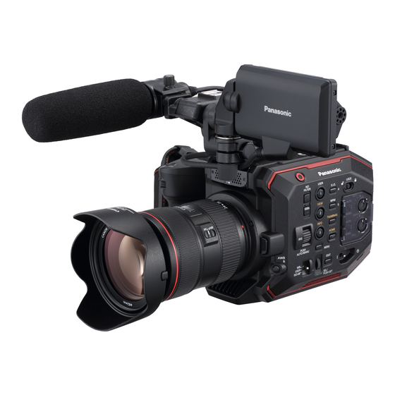
- Page 1 Operating Instructions Memory Card Camera-Recorder AU-EVA1 Model No. Before using this product, be sure to read “Read this first!” (pages 2 to 6). Before operating this product, please read the instructions carefully and save this manual for future use. ENGLISH...
-
Page 2: Read This First
Read this first! Read this first! indicates safety information. CAUTION: CAUTION Danger of explosion or fire if battery is incorrectly RISK OF ELECTRIC SHOCK replaced or mistreated. DO NOT OPEN • Do not disassemble the battery or dispose of it CAUTION: TO REDUCE THE RISK OF ELECTRIC SHOCK, in fire. - Page 3 Operation at a voltage other than 120 V AC may require the use of a different AC plug. Please contact either a local or foreign Panasonic authorized service center for assistance in selecting an alternate AC plug. FCC NOTICE (USA)
- Page 4 Read this first! indicates safety information. NOTIFICATION (Canada) CAN ICES-3(B)/NMB-3(B) The rating plate is on the underside of the Camera Recorder, Battery Charger and AC Adaptor. IMPORTANT SAFETY INSTRUCTIONS 1) Read these instructions. 2) Keep these instructions. 3) Heed all warnings. 4) Follow all instructions.
- Page 5 Read this first! Brazil Only Brasil Apenas r Manuseio de baterias usadas BRASIL Após o uso, as pilhas e /ou baterias poderão ser entregues ao estabelecimento comercial ou rede de assistência técnica autorizada. Cobrir os terminais positivo (+) e negativo (-) com uma fita isolante adesiva, antes de depositar numa caixa destinada para o recolhimento.
- Page 6 Batteries that may be used with this product (as of October 2017) Panasonic AG-VBR59 / AG-VBR89 / AG-VBR118 / VW-VBD58 batteries may be used with this product. It has been found that counterfeit battery packs which look very similar to the genuine product are made available to purchase in some markets.
- Page 7 SDXC logo is a trademark of SD-3C, LLC. f AVCHD, AVCHD Progressive, and AVCHD Progressive logo are trademarks of Panasonic Corporation and Sony Corporation. f This is manufactured based on license from Dolby Laboratories, Inc. Dolby, Dolby Audio, and the double-D symbol are trademarks of Dolby Laboratories.
-
Page 8: Table Of Contents
Contents Contents Read this first! VIEW screen Thumbnail screen Chapter 1 Overview Basic operation of the menu Configuration of the menu Before using the camera Displaying the menu Accessories Operating the menu Setting the region of use Initializing the menu [AREA SETTINGS] Menu setting contents [TIME ZONE]... - Page 9 Contents Direct volume control function Confirming audio input setting Chapter 6 Playback Thumbnail operation Thumbnail operation overview Thumbnail screen Copying clips Deleting clips Protecting clips Restoring clips Playing back clips Useful playback function Resume play Chapter 7 Output and Screen Display Output format Format that can be output from the <SDI OUT>...
-
Page 10: Chapter 1 Overview
Overview Chapter 1 Before using the camera, read this chapter. -
Page 11: Before Using The Camera
Chapter 1 Overview — Before using the camera Before using the camera r Before using the camera, always check if the built-in battery is not consumed, and then set the date/time. The internal clock of the camera is reset when the built-in battery has been consumed. This may result in the meta data of the clip not recorded correctly, and it may not display correctly in the thumbnail screen. - Page 12 Panasonic will not assume liability when video or audio recording fails due to a malfunction of the camera or the memory card during the use. f Set the calendar (datetime of the internal clock) and the time zone, or check the setting before recording. This will have an effect on the management of the recorded contents.
- Page 13 Do not install in a location where the camera, cable, etc., can be easily damaged. r Security Take caution so the camera is not stolen, lost, or neglected. Note that Panasonic is not liable to leakage, falsification, or loss of information caused by them.
-
Page 14: Accessories
Chapter 1 Overview — Accessories Accessories Battery (Parts No.: AG-VBR59) (page 30) Grip (page 35) f Already mounted to the camera. Battery charger (Parts No.: AG-BRD50) (page 30) Grip belt (page 35) f Already mounted to the grip. AC adaptor (page 30) LCD monitor (page 38) AC cable (page 30) f For AC adaptor... -
Page 15: Setting The Region Of Use
Chapter 1 Overview — Setting the region of use Setting the region of use The camera is shipped with the region of use not set. [AREA SETTINGS] is displayed in the LCD monitor when the power is turned on for the first time. Follow the guidance and make the settings in the order of [AREA SETTINGS], [TIME ZONE], and then [CLOCK SETTING]. -
Page 16: [Clock Setting]
Chapter 1 Overview — Setting the region of use [CLOCK SETTING] Once the setting for [TIME ZONE] is completed, the [CLOCK SETTING] screen is displayed. Set the year, month, date, and time. Set the year, month, date, and time. Select [SET]. Once the setting is completed, the VIEW screen is displayed in the LCD monitor. -
Page 17: Use Of The Camera On A System
“Preparing the SD card” * For the latest information not included in these Operating Instructions, refer to the support desk at the following website. https://pro-av.panasonic.net/ Expanded configuration devices In addition to the basic components, a wireless module can be used. -
Page 18: What You Can Do With This Camera
Connecting to monitor A monitor can be connected to output images. f Use the double shielded cable supporting 4K/60P as the HDMI cable (optional). It is also recommended to use the Panasonic 4K/60P compatible HDMI cable. f For the BNC cable (optional) connected to the <SDI OUT> terminal, prepare a double-shielded cable equivalent to 5C-FB. -
Page 19: Chapter 2 Description Of Parts
Description of Parts Chapter 2 This chapter describes the names, functions, and operations of parts on the camera. -
Page 20: Camera
Chapter 2 Description of Parts — Camera Camera Left side Following terminal is inside the cover. f <LCD> terminal 1 Accessory mounting section The included LCD monitor mounting attachment can also be mounted. 2 HDMI cable clamp Fixes the HDMI cable. 3 Microphone cable clamp Fixes the external microphone cable. -
Page 21: Right Side
Chapter 2 Description of Parts — Camera Right side 20 21 1 LCD monitor unit mounting section Mounts the included LCD monitor mounting attachment. 2 Handle This is a removable handle. Already mounted to the camera. 3 REC button Starts or stops the recording. 4 <ND FILTER>... -
Page 22: Front Side
Chapter 2 Description of Parts — Camera 13 Power lamp Indicates the status of power. Illuminates in red when the power is on. To flash the lamp or not can be set in the menu. 14 Built-in speaker Outputs audio during playback. Audio is not output from the built-in speaker when headphones are connected to the headphone terminal. -
Page 23: Rear Side
Chapter 2 Description of Parts — Camera 3 Front tally lamp Illuminates when the recording is started. Flashes when the battery level becomes low. To flash the lamp or not can be set in the menu. 4 EF lens mount EF lens is mounted. -
Page 24: Top Side
Chapter 2 Description of Parts — Camera 8 <HDMI> terminal A terminal to output video signal by connecting a monitor, etc. 9 <USB2.0 HOST> terminal Can connect to wireless LAN when the wireless module (optional) compatible to camera is mounted. 10 <SERVICE>... -
Page 25: Bottom Side
Chapter 2 Description of Parts — Camera Bottom side 1 Tripod holes Attach the tripod. f Mounting hole size - 1/4-20 UNC (screw length 5.5 mm or shorter) - 3/8-16 UNC (screw length 5.5 mm or shorter) – 25 –... -
Page 26: Lcd Monitor Unit
Chapter 2 Description of Parts — LCD monitor unit LCD monitor unit 1 LCD monitor hood Blocks the light from outside, making it easier to view the LCD monitor. 2 LCD monitor Displays the screen to set the basic setting of the camera and check the status of the camera. In addition to the HOME screen that is the starting point of the operation, the VIEW screen that displays the recording image, the INFO screen that displays the information of the camera, etc., can be displayed. -
Page 27: Grip
Chapter 2 Description of Parts — Grip Grip The grip is already mounted to the camera. 1 <EXIT>/<USER 8> button Returns to one level higher from the current menu when the menu is displayed. Pressing the <EXIT> button without confirming the setting value will not reflect the change in the setting. -
Page 28: Basic Operation
Chapter 2 Description of Parts — Basic operation Basic operation Multidial operation Operate the multidial on the camera by turning it in vertical direction or pushing it. f Turning the multidial in vertical direction will move the cursor. f Pressing the multidial will select or confirm the item with cursor. NOTE t For details on menu operation method, refer to “When operating with the multidial”. -
Page 29: Chapter 3 Preparation
Preparation Chapter 3 Before you use the camera, mount the battery following the procedures in this chapter. The mounting of accessories is also described in this chapter. -
Page 30: Power Supply
Chapter 3 Preparation — Power supply Power supply A battery or the supplied AC adaptor can be used as the power supply for the camera. f The camera is compatible to following batteries. (As of October 2017) - AG-VBR59 (supplied/optional, supports quick charging) - AG-VBR89 (optional, supports quick charging) - AG-VBR118 (optional, supports quick charging) - VW-VBD58 (optional) - Page 31 Chapter 3 Preparation — Power supply Standard charging time and recording time Battery parts number Voltage/capacity (minimum) Charging time Continuous shootable time AG-VBR59 (supplied/optional) 7.28 V/5900 mAh Approx. 3 hours 20 minutes Approx. 2 hours 50 minutes AG-VBR89 (optional) 7.28 V/8850 mAh Approx.
-
Page 32: Attaching And Removing The Battery
Chapter 3 Preparation — Power supply Attaching and removing the battery Attaching the battery Press the battery against the battery mounting section of the camera, and mount it by sliding it downward. f Press in the battery until it clicks and gets locked. Removing the battery Battery release button Set the power switch to <... -
Page 33: Using The Ac Adaptor
Chapter 3 Preparation — Power supply Using the AC adaptor Attaching the AC adaptor Use the supplied AC adaptor. Do not use an AC adaptor for other device. The supplied AC cable is dedicated for this camera. Do not use with any other device. Also, do not use AC cable from other device on this camera. To the power outlet Fig. -
Page 34: Mounting Accessories
Chapter 3 Preparation — Mounting accessories Mounting accessories Handle The handle is already mounted to the camera. Mounting the handle Mount the handle to the accessory mounting holes at the top of the camera body using the handle mounting screws (x 2). NOTE t Use the handle after securely tightening the handle mounting screws (x 2). -
Page 35: Grip
Chapter 3 Preparation — Mounting accessories Grip The grip is already mounted to the camera. Mounting the grip Mount reference points Fig. 1 Fig. 2 Grip cable clamp <REMOTE> terminal Grip cable Fig. 3 Insert the grip to the camera. (Fig. 1) f Align the mount reference points on the grip mounting section of the camera and the grip mounting section of the grip when inserting into the camera. - Page 36 Chapter 3 Preparation — Mounting accessories r Adjusting the angle of the grip Grip rotation lever Pull the grip rotation lever to the <UNLOCK> side. Adjust the angle of the grip, and return the grip rotation lever at the position to fix. The grip is fixed.
- Page 37 Chapter 3 Preparation — Mounting accessories Removing the grip <GRIP RELEASE> button Remove the grip cable from the grip cable clamp. Remove the grip cable from the <REMOTE> terminal. While pressing the <GRIP RELEASE> button on the camera, turn the grip clockwise. NOTE t Remove the grip after placing the camera body on a level location, such as desk.
-
Page 38: Lcd Monitor Unit
Chapter 3 Preparation — Mounting accessories LCD monitor unit Mounting the LCD monitor unit Mount the supplied LCD monitor unit to the LCD monitor mounting section. Screw Fig. 1 Fig. 2 Fig. 3 Insert the supplied LCD monitor mounting attachment to the LCD monitor unit mounting section of the handle. (Fig. 1) f This can also be mounted to the accessory mounting holes at the top of the camera. - Page 39 Chapter 3 Preparation — Mounting accessories Removing the LCD monitor unit Remove in the reverse procedure as mounting. NOTE t To disconnect the LCD monitor unit cable, pull out while pressing on the lock buttons on both sides of the cable connection terminal (s). LCD monitor hood The LCD monitor hood is already mounted to the LCD monitor unit.
-
Page 40: Attaching The Shoulder Strap
Chapter 3 Preparation — Mounting accessories Mounting the LCD monitor hood Align the tabs at the top of the LCD monitor hood (2 locations) to the dimples at the top of the LCD monitor unit. Align the tabs at the bottom of the LCD monitor hood (2 locations) to the dimples at the bottom of the LCD monitor unit. Attaching the shoulder strap Mount the supplied shoulder strap to the shoulder strap mounting section. -
Page 41: Mounting The External Microphone
Chapter 3 Preparation — Mounting accessories Mounting the external microphone External microphone such as the super-directional microphone AG-MC200G (optional) can be mounted onto the handle. Microphone holder adaptor Microphone holder Screw for the microphone holder Fig. 1 Fig. 2 Screw Microphone cable clamp <AUDIO INPUT 1>... -
Page 42: Mounting The Lens
Chapter 3 Preparation — Mounting accessories Mounting the lens Mount/remove the lens in a location away from direct sunlight or intense lighting. Take care not to drop the camera or the lens. Prevent dirt or dust from entering into the EF lens mount. Mount cap Mark Fig. -
Page 43: Attaching A Tripod
Chapter 3 Preparation — Mounting accessories f Mount the mount cap turning in clockwise direction with the mark on the mount cap at the top. NOTE t Do not touch the EF lens mount and inside the EF lens mount. t Attach the mount cap to the EF lens mount. -
Page 44: Turning On/Off The Power
Chapter 3 Preparation — Turning on/off the power Turning on/off the power Power switch How to turn on the power Set the power switch to < > (ON). The power lamp will illuminate in red when the power is on. f The [AREA SETTINGS] screen is displayed when the power is turned on for the first time. -
Page 45: Charging The Built-In Battery
Chapter 3 Preparation — Charging the built-in battery Charging the built-in battery The date/time set in the camera is maintained by the built-in battery. The built-in battery may exhaust when the camera is not turned on for approximately two months. The built-in battery is exhausted when [BACKUP BATT EMPTY] is displayed on the LCD monitor when the power switch is set to <... -
Page 46: Setting The Date/Time Of The Internal Clock
Chapter 3 Preparation — Setting the date/time of the internal clock Setting the date/time of the internal clock The date/time/time zone are recorded as meta data in the clip while shooting. It will affect the management of the recorded contents, so always check and set the date/time and time zone before using the camera for the first time. Do not change the setting of the date/time and time zone while shooting. -
Page 47: Preparing The Sd Card
48 GB - 128 GB f Operation is not guaranteed for any SD cards other than above. f It is recommended to use the Panasonic SD card. f Following SD cards cannot be used since they are not compliant with the SD standards. -
Page 48: Inserting/Removing Of The Sd Card
Chapter 3 Preparation — Preparing the SD card Card access lamp SD card status Recognizing the SD card The SD card is being recognized. Orange (rapidly flashing) An error has occurred. This will flash even if the SD card is not inserted Error when an error has occurred. -
Page 49: Formatting The Sd Card
Chapter 3 Preparation — Preparing the SD card f Avoid charging with electricity. Use or store the SD card with the card inserted into the camera and with the slot cover closed. Formatting the SD card Select the [REC SETTINGS] menu → [CARDS/MEDIA] → [FORMAT MEDIA] → [SLOT1]/[SLOT2]. When the confirmation message is displayed, select [SET]. -
Page 50: Handling Of The Recording Data
Chapter 3 Preparation — Preparing the SD card Recording capacity Recording format Recording rate 64 GB 128 GB 21 Mbps Approx. 6 hours Approx. 12 hours 30 minutes 17 Mbps Approx. 8 hours 30 minutes Approx. 17 hours 8 Mbps Approx. - Page 51 Video format: Progressive recording (MOV, LPCM) File name of the MOV format video data The file name format is the same as Panasonic VARICAM series (AU-V35LT1G, etc) CINE format. Clip can be managed in the same manner as VARICAM.
- Page 52 Chapter 3 Preparation — Preparing the SD card t Number of clips that can be recorded on a single SD card is approximately 4000. Data will not be able to record when it reaches the maximum number of clips that can recorded even if number in between is open. –...
-
Page 53: Setting Of Time Data
Use with this setting when using the frame rate information of the user bits with an editing device such as a PC. Use this setting to control the recording operation in TYPE1 or TYPE2 method against the Panasonic recorder (AJ-PG50, etc.). -
Page 54: Setting The Time Code
Chapter 3 Preparation — Setting of time data Memory function of the user bits Setting contents of the user bits is automatically recorded, and it is maintained even if the power is set to < > (standby). Frame rate information The relationship between frame rate, image pull-down, time code, and user bits is as follows. -
Page 55: Presetting The Time Code To External
Chapter 3 Preparation — Setting of time data Time code with variable frame rate record The time code is fixed to [REC RUN] when the variable frame rate recording function is set to enable. The time code will advance in the speed corresponding to the ratio setting values of [FREQUENCY] (system frequency) and [FPS] (frame rate). -
Page 56: Supplying The Time Code Externally
Chapter 3 Preparation — Setting of time data Supplying the time code externally The time code output from the camera corresponding to the camera video or the playback video can be supplied to an external recording device. <SDI OUT> terminal SDI IN terminal VTR, etc. -
Page 57: Assigning Function To The User Buttons
Chapter 3 Preparation — Assigning function to the USER buttons Assigning function to the USER buttons Selected function can be assigned to the USER buttons. f The buttons that can be used as a USER button are as follows. - <USER 1> to <USER 9> buttons These can be used as the USER buttons when the VIEW screen is displayed. -
Page 58: Checking The Function Assigned To The User Buttons
Chapter 3 Preparation — Assigning function to the USER buttons NOTE t Following functions will be disabled when the camera is set to < > (standby) and then turned on again. [ATW LOCK], [D.ZOOM], [EXPAND], [PEAK./SQUARES F.A.], [WFM], [SPOT METER], [LCD CLEAN VIEW], [COLOR BARS], [POWER LCD] t Following functions will be enabled when the camera is set to <... -
Page 59: Tally Lamp
Chapter 3 Preparation — Tally lamp Tally lamp The front tally lamp and the rear tally lamp can be illuminated during the shooting. Select the [SYSTEM SETTINGS] menu → [LED & FAN] → [TALLY LED] → [FRONT]/[REAR]/[BOTH]. f The tally lamp will flash when the camera is in the following status. ‑... -
Page 60: Chapter 4 Operation
Operation Chapter 4 This chapter describes how to operate the screen of this camera, how to operate the menu, the structure of the menu, and details of the menu. -
Page 61: Basic Operation Of The Screen
Chapter 4 Operation — Basic operation of the screen Basic operation of the screen Major button operation and screen display 1 <VIEW> button 2 <INFO> button 3 <THUMBNAIL> button 4 <HOME> button r <VIEW> button Displays the VIEW screen. Displays the shooting screen. The VIEW screen is displayed when the camera is turned on. -
Page 62: Major Button Operation And Switching Screen
Chapter 4 Operation — Basic operation of the screen Major button operation and switching screen Switches the screen as follows when the <HOME> button, <INFO> button, <VIEW> button, or <THUMBNAIL> button is pressed. Thumbnail screen HOME screen VIEW screen Clip information INFO screen 1 <HOME>... -
Page 63: Displaying The Home Screen
Chapter 4 Operation — Displaying the HOME screen Displaying the HOME screen Status of the camera can be confirmed. 1 [FPS] Displays the setting status of the variable frame rate recording function and the recording frame rate. 2 [COLOR] Displays the color setting of the video recorded to the main recorder. 3 [SHUTTER] Displays the shutter speed. - Page 64 Chapter 4 Operation — Displaying the HOME screen 11 Wireless LAN connection status display Displays the connection status of the wireless LAN. (No display): When the [NETWORK SETTINGS] menu → [NETWORK SEL] → [OFF] is set : When ROP is not connected : When ROP is connected 12 Power status display Displays the remaining battery level, or the drive status of the AC adaptor.
-
Page 65: Operating Each Screen
Chapter 4 Operation — Operating each screen Operating each screen The HOME screen, which is the starting point of screen operation is displayed by pressing the <HOME> button. Display the HOME screen, select [FPS], [COLOR], [SHUTTER], [EI], [AUDIO], or [WB], and change the value, etc., in the displayed screen. f There is a method to operate with the multidial or a grip multidial, or a method to operate by touching the LCD monitor. - Page 66 Chapter 4 Operation — Operating each screen r [VFR] display When the [CAMERA SETTINGS] menu → [FPS] → [VFR SW] → [ON] is set, [VFR] is displayed at the top left of [FPS], and recorded with the frame rate set in [FPS]. Audio cannot be recorded when [FREQUENCY] and [FPS] are different. When the [CAMERA SETTINGS] menu →...
- Page 67 Chapter 4 Operation — Operating each screen [EI] The EI screen is displayed when [EI] is selected in the HOME screen, allowing to set EXPOSURE INDEX (gain), and to set the operation in accordance with the setting of the [CAMERA SETTINGS] menu → [EI] → [MODE]. [NATIVE ISO]/[800BASE ISO]/[2500BASE ISO]/[GAIN SELECT]: The VIEW screen is displayed, and EXPOSURE INDEX (gain) can be set.
-
Page 68: Info Screen
Chapter 4 Operation — Operating each screen [WB] When [WB] is selected in the HOME screen, the VIEW screen is displayed, allowing to set the color temperature (white balance). f Select from the previously registered white balance setting values in [`]/[{]. f The white balance setting value can be added/deleted in the [CAMERA SETTINGS] menu →... -
Page 69: Basic Operation Of The Menu
Chapter 4 Operation — Basic operation of the menu Basic operation of the menu The setting of the camera can be changed with the menu in accordance to the shooting scene or recording contents. Set data is written and saved in the camera memory. f There is a method to operate with the multidial or a grip multidial, or a method to operate by touching the LCD monitor. -
Page 70: Displaying The Menu
Chapter 4 Operation — Basic operation of the menu Displaying the menu Displays the menu, and select the menu or item to set. Press the <MENU> button when not recording. The menu is displayed. 1 Level display Displays the path of the menu to the currently displayed screen. 2 [`]/[{] Moves the cursor up or down when selected. -
Page 71: Operating The Menu
Chapter 4 Operation — Basic operation of the menu Operating the menu Various settings are possible from the menu. There are two methods of operation, a method to operate with the multidial or grip multidial, or a method to touch the LCD monitor. When operating with the multidial Operate the multidial on the camera by turning it in vertical direction or pushing it. -
Page 72: Initializing The Menu
Chapter 4 Operation — Basic operation of the menu When operating by touching the LCD monitor Operate by touching the LCD monitor. Press the <MENU> button when not recording. The menu is displayed. f Menu is displayed even when the LCD monitor is touched for one second or longer and then released while the VIEW screen is displayed. Select the menu to set. -
Page 73: Menu Setting Contents
Chapter 4 Operation — Menu setting contents Menu setting contents [THUMBNAIL] menu Performs confirmation or deleting of the recording clip. This menu can be set when the thumbnail screen is displayed. [PLAYBACK] [SLOT SEL] Selects a clip to be displayed on the thumbnail screen. [ALL SLOT] Displays the clips recorded on all the SD cards in each card slot. - Page 74 Chapter 4 Operation — Menu setting contents [CROP&MIX 2K] Performs the RAW output of the 2048×1080 pixels by cutting out the center section of the image sensor and performing the pixel mixing read. This allows high-speed shooting up to 240p. Angle of view will change. (Factory setting: [OFF]) NOTE t When the [SYSTEM SETTINGS] menu →...
- Page 75 Chapter 4 Operation — Menu setting contents [COLOR SETTINGS] [MAIN] Sets the colors of videos (entire camera system) recorded in the main recorder. [V-Log] Sets to the gamma curve that can achieve gradation and wide latitude (exposure range). A grading process after recording is required.
- Page 76 Chapter 4 Operation — Menu setting contents [USER4] Sets the function to assign to the <USER 4> button. (Factory setting: [E.I.S.]) [USER5] Sets the function to assign to the <USER 5> button. (Factory setting: [WFM]) [USER6] Sets the function to assign to the <USER 6> button. (Factory setting: [AWB]) [USER7] Sets the function to assign to the <USER 7>...
- Page 77 Chapter 4 Operation — Menu setting contents [USER7] Sets if the <USER 7> button is to be locked or not with the <LOCK> switch. [LOCK] It will be locked. [UNLOCK] It will not be locked. (Factory setting: [LOCK]) [THUMBNAIL] Sets if the <THUMBNAIL> button is to be locked or not with the <LOCK> switch. [LOCK] It will be locked.
- Page 78 Chapter 4 Operation — Menu setting contents [ACCESS LED] Sets if the card access lamp is to illuminate or not. The items that can be set are as follows. f [ON], [OFF] (Factory setting: [ON]) [POWER LED] Sets if the power lamp is to illuminate or not. The items that can be set are as follows.
-
Page 79: [Camera Settings] Menu
Chapter 4 Operation — Menu setting contents [DATE FORMAT] Sets the display order of the year, month, and date of the calendar (date of the built-in clock). This is reflected to the date display of the clip information. The items that can be set are as follows. f [Y-M-D], [M-D-Y], [D-M-Y] (Factory setting: [Y-M-D] (when [AREA SETTINGS] is set to [AREA 1]), [M-D-Y] (when [AREA SETTINGS] is set to [AREA 2]), [D-M-Y] (when [AREA SETTINGS] is set to [AREA 3])) - Page 80 Chapter 4 Operation — Menu setting contents [SW] Enables/disables the shutter function. The items that can be set are as follows. f [ON], [OFF] (Factory setting: [ON]) [MODE] Sets the displaying method of the shutter speed. [sec] Displays in time. [deg] Displays in the shutter aperture angle.
- Page 81 Chapter 4 Operation — Menu setting contents [ISO SELECT] Sets the operation when [ISO] is selected in [MODE] of [EI]. The items that can be set are as follows. f [NATIVE ONLY], [800BASE], [2500BASE] (Factory setting: [NATIVE ONLY]) [NATIVE ISO] Sets the value when [NATIVE ONLY] is selected in [ISO SELECT] of [EI].
- Page 82 Chapter 4 Operation — Menu setting contents [WHITE] [AWB] Executes the adjustment of auto white balance. This can be executed when [VALUE] is set to [AWB MEMORY]. The items that can be selected are as follows. f [EXECUTE], [CANCEL] [VALUE] Selects the adjustment value of auto white balance.
-
Page 83: [Scene File Settings] Menu
For the latest information regarding the EF lens supporting the acquisition of the focal distance information with the communication between the camera and the lens, refer to the support desk at the following website. https://pro-av.panasonic.net/ [ZOOM POSITION VALUE] Sets the focal distance (mm) used when [ZOOM POSITION DATA] is set to [MANUAL]. - Page 84 Chapter 4 Operation — Menu setting contents For details of saving and loading, refer to “Handling setting data”. [LOAD] Loads the scene file saved in the camera memory, and reflects to the current setting value. The items that can be selected are as follows. f [YES], [NO] [SAVE] Saves the current setting value as a scene file into the camera memory.
- Page 85 Chapter 4 Operation — Menu setting contents [B.GAMMA RANGE] Sets the maximum level to perform compression/expansion of dark area. The items that can be set are as follows. Around 20% Around 30% Around 40% [KNEE] [KNEE SW] Enables/disables operation of the knee. The items that can be set are as follows.
- Page 86 Chapter 4 Operation — Menu setting contents [CORING] Sets the level of coring against the detail. The items that can be set are as follows. f [0]…[60] [MASTER LEVEL] Sets the level of the detail effect of the whole part. The items that can be set are as follows.
-
Page 87: [Rec Settings] Menu
Chapter 4 Operation — Menu setting contents [(B-G)] Adjusts the linear matrix. (Blue - Green) The items that can be set are as follows. f [−63]…[63] [COLOR CORRECTION] For details of setting, refer to “[COLOR CORRECTION]”. [SW] Enables/disables the color correction function. The items that can be set are as follows. - Page 88 Chapter 4 Operation — Menu setting contents [PRE REC] Sets whether to perform pre-recording. The pre-recording time differs depending on the setting of the [SYSTEM SETTINGS] menu → [SYSTEM MODE] → [MAIN PIXEL]/[MAIN CODEC]. [ON] Performs the pre-recording. The pre-recording time is as follows. f When [MAIN PIXEL] is [1280x720], [1920x1080], or [2048x1080]: Approximately 10 seconds f When [MAIN CODEC] is [422ALL-I 400M]: Approximately 3 seconds f Other than above: Approximately 5 seconds...
-
Page 89: [Audio Settings] Menu
Chapter 4 Operation — Menu setting contents NOTE t It will be fixed to [REC RUN] when the [CAMERA SETTINGS] menu → [FPS] → [VFR SW] → [ON] is set. t It will be fixed to [FREE RUN] when the [REC SETTINGS] menu → [PRE REC] → [ON] is set. t It will be fixed to [REC RUN] when the [REC SETTINGS] menu →... - Page 90 Chapter 4 Operation — Menu setting contents [CH2 MIC LOWCUT] Enables/disables the lowcut filter for audio channel 2. The items that can be set are as follows. f [ON], [OFF] (Factory setting: [OFF]) [CH1 LIMITER] Enables/disables the limiter when the method to adjust the audio input level for audio channel 1 is manual. The items that can be set are as follows.
- Page 91 Chapter 4 Operation — Menu setting contents The items that can be set are as follows. f [4dB], [0dB] (Factory setting: [4dB]) [INPUT2 LINE LEVEL] Sets the audio input level of the audio device connected to the <AUDIO INPUT 2> terminal. Enabled when the audio device is connected and [INPUT2 LINE/MIC SEL] of [AUDIO INPUT] is set to [LINE].
-
Page 92: [Output Settings] Menu
Chapter 4 Operation — Menu setting contents [OUTPUT SETTINGS] menu Sets the display content or output format of the video. [SDI OUT] [OUTPUT SW] Enables/disables the output from the <SDI OUT> terminal. [ON] Outputs the video. [OFF] Does not output the video. (Factory setting: [ON]) NOTE t It will be fixed to [ON] when the [SYSTEM SETTINGS] menu →... - Page 93 Chapter 4 Operation — Menu setting contents NOTE t This is not displayed in the output from the <SDI OUT> terminal when the menu is displayed in the LCD monitor. t When the [SYSTEM SETTINGS] menu → [SYSTEM MODE] → [SDI RAW] is set to anything other than [OFF], this cannot be set. [MARKER DISP] Sets if the marker set in [SDI/HDMI MARKER] is displayed or not in the output from the <SDI OUT>...
- Page 94 Chapter 4 Operation — Menu setting contents [HDMI REC REMOTE] Sets if the recording operation against the external equipment connected to the <HDMI> terminal (such as recorder) is to be controlled or not. This can be set when [HDMI TC OUT] in [HDMI OUT] is enabled. [ON] Controls the recording operation of the external equipment.
- Page 95 Chapter 4 Operation — Menu setting contents The items that can be set are as follows. f [ON], [OFF] (Factory setting: [ON]) [SLOT1/2 STATUS] Displays/hides the status of the card slot and remaining recordable capacity. The items that can be set are as follows. f [ON], [OFF] (Factory setting: [ON]) [2 SLOTS FUNC.]...
- Page 96 Chapter 4 Operation — Menu setting contents (Factory setting: [ON]) [IRIS/ZOOM] Displays/hides the lens aperture value and zoom value. The items that can be set are as follows. f [ON], [OFF] (Factory setting: [ON]) [ND FILTER] Displays/hides the ND filter transmittance. The items that can be set are as follows.
- Page 97 Chapter 4 Operation — Menu setting contents [FRAME MARKER] Sets the aspect ratio of the frame marker. The frame marker is not displayed when [OFF] is selected. The items that can be set are as follows. f [1.33:1], [1.44:1], [1.56:1], [1.78:1], [1.85:1], [2.00:1], [2.201:1], [2.35:1], [2.39:1], [OFF] (Factory setting: [OFF]) [FRAME COLOR] Sets the color of the frame marker.
- Page 98 Chapter 4 Operation — Menu setting contents [BATTERY REMAIN] Displays/hides the power status display. The items that can be set are as follows. f [ON], [OFF] (Factory setting: [ON]) [REC MODE] Displays/hides the status of the interval recording. The items that can be set are as follows. f [ON], [OFF] (Factory setting: [ON]) [REC REMOTE]...
- Page 99 Chapter 4 Operation — Menu setting contents The items that can be set are as follows. f [ON], [OFF] (Factory setting: [ON]) [IR SHOOTING] Displays/hides the setting in the [CAMERA SETTINGS] menu → [IR SHOOTING]. The items that can be set are as follows. f [ON], [OFF] (Factory setting: [ON]) [SPOT METER]...
- Page 100 Chapter 4 Operation — Menu setting contents [LCD FOCUS ASSIST] [EXPAND MODE] Sets the enlargement display function mode. [10SEC] Disables the enlarged display function after ten seconds have elapsed. [HOLD] The enlarged display function is enabled until the USER button assigned with [EXPAND] is pressed again. [UNTIL REC] Enables the enlarged display function until performing recording operation.
- Page 101 Chapter 4 Operation — Menu setting contents [ZEBRA2 DETECT] Sets the detection level of zebra pattern 2. The items that can be set are as follows. f [0%]…[109%] (Factory setting: [100%]) [ZEBRA2] Enables/disables zebra pattern 2 and selects [SPOT]. The items that can be set are as follows. f [ON], [SPOT], [OFF] (Factory setting: [OFF]) [WFM MODE]...
-
Page 102: [File] Menu
(Factory setting: [DIRECT]) [SSID] Enters or displays the network name of the camera (SSID). (Factory setting: [AU-EVA1]) [BAND] Switches between two communication methods ([2.4GHz] or [5GHz]) when [NETWORK PROPERTY] → [TYPE] → [DIRECT] is selected. The items that can be set are as follows. - Page 103 Chapter 4 Operation — Menu setting contents The items that can be set are as follows. f [AUTO], [CH1], [CH6], [CH11] (Factory setting: [AUTO]) [CHANNEL(5GHz)] Sets the channel to be used when connected to the wireless LAN with following items set. f The [NETWORK SETTINGS] menu →...
-
Page 104: [Option] Menu
Chapter 4 Operation — Menu setting contents [CONNECTION HISTORY] Displays the connection history with the wireless access point. Maximum of 20 histories that were recently connected can be saved. [SELECT] The list of connection history is displayed when [SELECT] is selected. Connection can be made using previous setting by selecting the wireless access point to connect from the list. -
Page 105: Factory Setting Value Of The Scene File
Chapter 4 Operation — Factory setting value of the scene file Factory setting value of the scene file [SCENE FILE SETTINGS] menu The factory setting values and items that can be selected in [SCENE FILE SETTINGS] differ depending on the [SYSTEM SETTINGS] menu → [COLOR SETTINGS] →... - Page 106 Chapter 4 Operation — Factory setting value of the scene file [MAIN] Item [SCENE1 (eV-LOOK1)]* [SCENE2 (eV-LOOK2)]* [SCENE3 (BC-LOOK1)]* [SCENE4 (BC-LOOK2)]* [SCENE5 (HDR)]* [P2]([SAT]) [P2]([PHASE]) [P3]([SAT]) [P3]([PHASE]) [Yl]([SAT]) [Yl]([PHASE]) [P4]([SAT]) [P4]([PHASE]) [P5]([SAT]) [P5]([PHASE]) [G]([SAT]) [G]([PHASE]) [P6]([SAT]) [P6]([PHASE]) [Cy]([SAT]) [Cy]([PHASE]) [P7]([SAT]) [P7]([PHASE]) [B]([SAT]) [B]([PHASE])
-
Page 107: Target Items For Scene File/Setup File/Initialization
Chapter 4 Operation — Target items for scene file/setup file/initialization Target items for scene file/setup file/initialization f SCENE: Items saved in scene files. f SETUP: Items saved in setup files. f INITIALIZE: Items that are initialized with the [SYSTEM SETTINGS] menu → [INITIALIZE] → [LOAD FACTORY DATA]. f Meaning of the symbols used in the table are as follows. -
Page 108: [Camera Settings] Menu
Chapter 4 Operation — Target items for scene file/setup file/initialization Item SCENE SETUP INITIALIZE [LCD] [BRIGHTNESS] — [COLOR LEVEL] — [CONTRAST] — [BACK LIGHT] — [CLOCK] [CLOCK SETTING] — — — [TIME ZONE] — — — [DATE FORMAT] — [INFORMATION] [VERSION] —... -
Page 109: [Scene File Settings] Menu
Chapter 4 Operation — Target items for scene file/setup file/initialization [SCENE FILE SETTINGS] menu Item SCENE SETUP INITIALIZE [NAME EDIT] — [SCENE DATA] [LOAD] — — — [SAVE] — — — [INITIALIZE] — — — [BLACK] [M.PED] — [R PED] —... -
Page 110: [Audio Settings] Menu
Chapter 4 Operation — Target items for scene file/setup file/initialization [AUDIO SETTINGS] menu Item SCENE SETUP INITIALIZE [AUDIO CH SETTINGS] [CH1 IN SELECT] — [CH2 IN SELECT] — [CH1 MIC LOWCUT] — [CH2 MIC LOWCUT] — [CH1 LIMITER] — [CH2 LIMITER] —... - Page 111 Chapter 4 Operation — Target items for scene file/setup file/initialization Item SCENE SETUP INITIALIZE [E.I.S./D.ZOOM] — [WLAN] — [IR SHOOTING] — [SPOT METER] — [PLAYBACK STATUS] — [SDI/HDMI MARKER] [CENTER MARKER] — [SAFETY MARKER] — [SAFETY AREA] — [FRAME MARKER] —...
-
Page 112: [File] Menu
Chapter 4 Operation — Target items for scene file/setup file/initialization [FILE] menu Item SCENE SETUP INITIALIZE [SCENE FILE] [LOAD] — — — [SAVE] — — — [SAVE AS] — — — [SETUP FILE] [LOAD] — — — [SAVE] — — —... -
Page 113: Handling Setting Data
Chapter 4 Operation — Handling setting data Handling setting data Scene files File structure of the setting data The scene files of [SCENE1] to [SCENE5] can be saved in the camera memory in accordance to the scene file number. What can be saved as a scene file is the setting contents of the [SCENE FILE SETTINGS] menu. Also, the current setting value of the scene files [SCENE1] to [SCENE5] can be saved as a file to the camera memory and the SD card, and that data can be read and used in the camera. -
Page 114: Setup File
Chapter 4 Operation — Handling setting data Saving the scene file as a new file in the SD card Saves the current setting value of the camera into the SD card in the card slot 1 as a new file by specifying the file name. Select the [FILE] menu →... - Page 115 Chapter 4 Operation — Handling setting data Select the file to overwrite from the list of setup files. The file name entry screen and the keyboard are displayed. Leave it as is when overwriting. Select [Enter]. A confirmation screen is displayed. Select [SET].
-
Page 116: Chapter 5 Shooting
Shooting Chapter 5 This chapter describes the basic procedure for recording. This chapter also describes the special recording method. -
Page 117: Shooting
Chapter 5 Shooting — Shooting Shooting For shooting, use the following steps. 1 REC button (camera body) 2 REC button (grip) Set the video settings and the audio input. f Before shooting, the followings must be set or adjusted. ‑ Image settings for the brightness function (iris, gain, shutter) and the white balance adjustment function, etc. ‑... - Page 118 Chapter 5 Shooting — Shooting When [FREQUENCY] is set to [23.98p] Can be set only when [SDI RAW] is set to [OFF]. [SENSOR MODE] [MAIN PIXEL] [MAIN CODEC] [S35 5.7K] [4096x2160] [420LongGOP 100M] 1fps - 60fps [422LongGOP 150M] 1fps - 30fps [422ALL-I 400M] [3840x2160] [420LongGOP 100M]...
- Page 119 Chapter 5 Shooting — Shooting [SENSOR MODE] [MAIN PIXEL] [MAIN CODEC] [3840x2160] [420LongGOP 100M] 1fps - 60fps [422LongGOP 150M] 1fps - 30fps [422ALL-I 400M] [2048x1080] [422LongGOP 50M] 1fps - 60fps [422ALL-I 100M] [1920x1080] [422LongGOP 50M] [422ALL-I 100M] [S35 MIX 2.8K] [2048x1080] [422LongGOP 50M] 1fps - 120fps...
-
Page 120: Selecting The Resolution And Frame Rate Of The Raw Output
Chapter 5 Shooting — Shooting When [FREQUENCY] is set to [50.00i] Can be set only when [SDI RAW] is set to [OFF]. [SENSOR MODE] [MAIN PIXEL] [MAIN CODEC] [S35 5.7K] [1920x1080] [422LongGOP 50M] — [422ALL-I 100M] [AVCHD PH] [AVCHD HA] Selecting the resolution and frame rate of the RAW output Resolution of the RAW output from the <SDI OUT>... -
Page 121: Image Quality Adjustment
Chapter 5 Shooting — Image quality adjustment Image quality adjustment The image quality of the video to be recorded can be adjusted in the camera when the [SYSTEM SETTINGS] menu → [COLOR SETTINGS] → [MAIN] → [SCENE1] to [SCENE5]is set. f Adjust the image quality in the [CAMERA SETTINGS] menu. -
Page 122: [Black]
Chapter 5 Shooting — Image quality adjustment f Required size of white pattern is as follows. 1/2 or more of the screen width 1/2 or more of the screen height f Keep bright spotlights out of the screen. f The white pattern must be placed at the center of the screen. Manually setting the color temperature (setting with [VALUE]) Can be selected from the up to 12 registered color temperatures (white balance). - Page 123 Chapter 5 Shooting — Image quality adjustment Output (%) -7.5 Input/Stop [V-Log] [V-255570L1] ([SCENE1]: EVA-LOOK) [V-504580L1] ([SCENE2]: EVA-LOOK) Output (%) [VIDEO] ([SCENE3]/[SCENE4]: BC-LOOK) [KNEE SW] = [ON] [KNEE POINT] = [85%] [KNEE SLOPE] = [100] Input/dynamic range (%) Output (%) -7.5 1200 Input/dynamic range (%)
-
Page 124: [Knee]
Chapter 5 Shooting — Image quality adjustment It is recommended to shoot at 40% to 55% for face tone. f [V-504580L1] This is the EVA-LOOK gamma curve with 14Stop latitude equivalent to [V-Log]. The rise is equivalent to approximately 5.0 times, and the gamma factor is 0.45, which means up to 80%. This is a setting focused on soft texture. -
Page 125: [Hlg Knee]
Chapter 5 Shooting — Image quality adjustment [KNEE MODE] (setting for knee operation mode) Select the [SCENE FILE SETTINGS] menu → [KNEE] → [KNEE SW] → [ON]. Select the [SCENE FILE SETTINGS] menu → [KNEE] → [KNEE MODE] → [D RANGE]/[PRESS]. [D RANGE]: Determines the dynamic range that can be represented by the [KNEE SLOPE] value. -
Page 126: [Skin Detail]
Chapter 5 Shooting — Image quality adjustment [SKIN DETAIL] A function to make human skin look smoother. Select the [SCENE FILE SETTINGS] menu → [SKIN DETAIL]. Set one of [SKIN DTL1]/[SKIN DTL2]/[SKIN DTL3] to [ON]. [SKIN DTL1]/[SKIN DTL2]/[SKIN DTL3] can be used in conjunction. [CHROMA] Sets the color saturation. -
Page 127: [Color Correction]
Chapter 5 Shooting — Image quality adjustment [COLOR CORRECTION] This function sets color saturation and phase. This affects individually against the 16 phases of the image. It can be set to individual color hue. (Yl-R)-R (Yl-R) Yl-(Yl-R) Yellow (G-Yl)-Yl (G-Yl) PHASE(+) Green SAT(-) -
Page 128: Variable Frame Rate (Vfr) Recording Function
Chapter 5 Shooting — Variable frame rate (VFR) recording function Variable frame rate (VFR) recording function It is possible to acquire smooth slow motion or quick motion vide by shooting with a different frame rate from the frame rate to play back. Variable frame rate (VFR) Allows the high-speed shooting from 1fps to maximum of 240fps. -
Page 129: Special Recording Function
Chapter 5 Shooting — Special recording function Special recording function Special recording such as pre-recording or relay recording is possible by setting the menu. Pre-recording Records the video and audio from specific time before the operation to start the recording. Operation to start recording Operation to stop recording (Time) -
Page 130: Simultaneous Recording
Chapter 5 Shooting — Special recording function t The recording is stopped once when the recording time of relay recording exceeds ten hours. The recording is automatically resumed after few seconds. t For recording limitation of the relay recording, refer to “Recording function that cannot be used simultaneously”. Simultaneous recording Insert SD cards into two card slots, and record the same video onto two SD cards. -
Page 131: Ir Shooting
Chapter 5 Shooting — Special recording function f To clear the setting, set the [REC SETTINGS] menu → [REC FUNCTION] → [REC MODE] to [NORMAL]. f The setting is not cleared even when the power is turned off. NOTE t Audio is not recorded. t Recorded data (data recorded until recording was stopped) is included in one clip. -
Page 132: Convenient Shooting Functions
Chapter 5 Shooting — Convenient shooting functions Convenient shooting functions Zebra patterns display The camera can display two types of zebra patterns to the output image from the <LCD> terminal. Select the [OUTPUT SETTINGS] menu → [LCD EI ASSIST] → [ZEBRA] → [ON]. f Factory setting: [OFF] Setting the detection level Set the [OUTPUT SETTINGS] menu →... -
Page 133: Displaying Frame Marker
Chapter 5 Shooting — Convenient shooting functions Setting the size of the frame. Select the size of the frame in the [OUTPUT SETTINGS] menu → [LCD MARKER] → [SAFETY AREA]. Displaying frame marker A frame marker can be displayed. From the [OUTPUT SETTINGS] menu → [LCD MARKER] → [FRAME MARKER], select the angle of view. f The frame marker is not displayed when [OFF] is selected. - Page 134 Chapter 5 Shooting — Convenient shooting functions r Using the enlarged display function Press the USER button that [EXPAND] is assigned. Press the USER button again to return to the normal display. Setting the mode for enlarged display function Select the mode for enlarged display function in the [OUTPUT SETTINGS] menu → [LCD FOCUS ASSIST] → [EXPAND MODE]. [10SEC]: Disables the enlarged display function after ten seconds have elapsed.
-
Page 135: Electronic Image Stabilization Function
Chapter 5 Shooting — Convenient shooting functions How to view the focus square display Adjust the focus so that the square size displayed in the area of the subject to be focused becomes the largest. When focused on the doll When the panel is focused NOTE t The peaking display/focus square display cannot be recorded. -
Page 136: Waveform Monitor Function
Chapter 5 Shooting — Convenient shooting functions Waveform monitor function Waveform of the image can be displayed. r Assigning [WFM] to the USER button Set this function so that the waveform monitor can be displayed/hidden with an arbitrary USER button. Select the [SYSTEM SETTINGS] menu →... -
Page 137: Color Bars
Chapter 5 Shooting — Convenient shooting functions NOTE t The display of level gauge cannot be recorded. t The level gauge is not displayed when the enlarged display function of the focus assist function is enabled, or when displaying the color bars. t The level gauge may not display correctly while moving the camera. -
Page 138: Audio Input
Chapter 5 Shooting — Audio input Audio input The camera can record two channels of audio. The audio to input to each channel can be switched to the built-in microphone, an external microphone, or a connected audio device. Switching the audio input r Audio recording format The audio recording format such as compression format varies depending on the recording mode. -
Page 139: Monitoring The Audio
Chapter 5 Shooting — Audio input Manual adjustment of the recording level Set the <CH1>/<CH2> switch to <MANU>. Adjust the recording level with the <AUDIO LEVEL CH1>/<AUDIO LEVEL CH2> dial. f When the input level of audio exceeds 0 dB, the level display exceeding 0 dB is displayed in red in the audio level meter in the HOME screen. This is indicating that the input volume is too high. -
Page 140: Confirming Audio Input Setting
Chapter 5 Shooting — Audio input Operate the multidial to adjust the audio level. Confirming audio input setting Setting of the audio input can be confirmed in the [AUDIO] screen. Press the <INFO> while the HOME screen is displayed. The INFO screen is displayed. Select [AUDIO]. -
Page 141: Chapter 6 Playback
Playback Chapter 6 Data including additional information such as image, audio, and meta data that are recorded by single shooting is saved as a clip. Playback, copy, etc., of the clip can be performed on the camera. -
Page 142: Thumbnail Operation
Chapter 6 Playback — Thumbnail operation Thumbnail operation Thumbnail operation overview A clip is a group of data recorded by a single shooting, which includes additional information such as image, audio, and meta data. The following operations can be performed while viewing the clip thumbnails displayed on the LCD monitor. f Playback, delete, and copy of a clip (only possible for a clip recorded in AVCHD) There is a method to operate with the multidial or a grip multidial, or a method to operate by touching the LCD monitor. - Page 143 Chapter 6 Playback — Thumbnail operation 9 Page switching button Switches the page of the thumbnail screen. [`]: Moves to previous page [{]: Moves to next page 10 Scroll bar Indicates which part of the whole thumbnail is currently being viewed. Display of the clips in the thumbnail screen 1 Thumbnail number Displays the thumbnail number in [0001] to [9999].
- Page 144 Chapter 6 Playback — Thumbnail operation r Clip information 1 Clip that cannot be played back This is displayed when the clip cannot be played back with the camera because the system frequency is different, etc. 2 Thumbnail number 3 Protection status of the clip This is displayed when the clip is protected.
-
Page 145: Copying Clips
Chapter 6 Playback — Thumbnail operation Copying clips Clip can be copied between the SD cards. Only the clip recorded in AVCHD can be copied. COPY Fig. 1 Fig. 2 Fig. 3 Fig. 4 Fig. 5 Press the <THUMBNAIL> button. The thumbnail screen is displayed. -
Page 146: Deleting Clips
Chapter 6 Playback — Thumbnail operation NOTE t The clip with MOV as the recording codec cannot be copied. t The copy is not possible when the volume of the selected clip is larger than the available card capacity of the destination. t It cannot copy when the copy destination card is write protected. -
Page 147: Restoring Clips
Chapter 6 Playback — Thumbnail operation Press the <MENU> button while the thumbnail screen is displayed. The menu is displayed. Select the [THUMBNAIL] menu → [CLIP] → [PROTECT]. Select [SELECT]. The thumbnail screen is displayed. Select the clip to protect in the thumbnail screen. is displayed on the selected clip. -
Page 148: Playing Back Clips
Chapter 6 Playback — Thumbnail operation Playing back clips From the [SYSTEM SETTINGS] menu → [SYSTEM MODE] → [FREQUENCY]/[MAIN PIXEL], select the system frequency and the number of recording pixels to play back. From the [SYSTEM SETTINGS] menu → [SYSTEM MODE] → [MAIN CODEC], select the codec (MOV or AVCHD) to play back. Press the <THUMBNAIL>... - Page 149 Chapter 6 Playback — Thumbnail operation Playback operation Operating procedure Slow playback Touch and hold during pause. is for reverse slow playback) It will perform slow playback with continuous frame-by-frame while touched. f It will return to normal speed playback by touching / . f The frame-by-frame interval and the display time for each frame for the reverse slow playback differ depending on the type of the clip.
-
Page 150: Useful Playback Function
Chapter 6 Playback — Useful playback function Useful playback function Resume play When the playback of a clip is stopped midway, it will start the playback from the position that stopped the playback when it is played back the next time. Select the [THUMBNAIL] menu →... -
Page 151: Chapter 7 Output And Screen Display
Output and Screen Display Chapter 7 This chapter describes the screen displayed on the output video and LCD monitor. -
Page 152: Output Format
Chapter 7 Output and Screen Display — Output format Output format The format to be output differs depending on the setting in the [SYSTEM SETTINGS] menu → [SYSTEM MODE] → [FREQUENCY]/[MAIN PIXEL]. Format that can be output from the <SDI OUT> terminal The format that can be output from the <SDI OUT>... -
Page 153: Format That Can Be Output From The
Chapter 7 Output and Screen Display — Output format Item Output Format [OUT FORMAT] [FREQUENCY] [MAIN PIXEL] [SIGNAL SEL] [LCD(1080p)] 1920×1080 over 50p* [LCD(1080i)] 1920×1080 over 50i* [3840x2160] [SDI] 3840×2160p 1920×1080p 1920×1080PsF (Factory setting) [LCD(1080p)] 1920×1080 over 50p* [LCD(1080i)] 1920×1080 over 50i* [2048x1080] [SDI] 1920×1080p*...Terminal - Page 154 Chapter 7 Output and Screen Display — Output format Item Output Format [OUT FORMAT] [FREQUENCY] [MAIN PIXEL] [SIGNAL SEL] [LCD(1080p)] 1920×1080 over 59.94p* [2048x1080] [HDMI] 1920×1080p* (Factory setting) [LCD(1080p)] 1920×1080 over 59.94p* [1920x1080] [HDMI] 1920×1080p (Factory setting) [LCD(1080p)] 1920×1080 over 59.94p* [24.00p] [4096x2160] [HDMI]...
-
Page 155: Screen Status Display
Chapter 7 Output and Screen Display — Screen status display Screen status display r During shooting A001C003 4096 x 2160 23.98p SCN1 MOV-422L 999min P 999min SIMUL TC 12:59:59:23 INTRVL +7.3STOP 23.98fps 180.0deg ISO12800 A15000K+10.0 F11.0A 1000.0mm ND:1.8 D1.4x 16 17 1 Clip name Displays the clip name being recorded with maximum of eight characters from beginning. - Page 156 Chapter 7 Output and Screen Display — Screen status display 6 Recording status (card slot 1) Displays the recording status of the SD card in the card slot 1. : Not target for recording. (flashing): Recognizing the SD card. : The recording is stopped with the recording target SD card is inserted. (flashing): Recognizing the SD card.
- Page 157 Chapter 7 Output and Screen Display — Screen status display 11 Time code Displays the time code, user bits, and duration in accordance with the [REC SETTINGS] menu → [TC] → [TC/UB/Dur.] setting. f [TC **:**:**:**]: Displays the time code. (Displayed black and white inverted when slave locked to the externally input time code) f [UB ** ** ** **]: Displays the user bits.
- Page 158 Chapter 7 Output and Screen Display — Screen status display 27 External equipment recording operation control status (<SDI OUT>/<HDMI> terminal) Displays the control status of the recording start and recording stop on the external equipment connected to the <SDI OUT> terminal and the <HDMI>...
-
Page 159: Chapter 8 Connecting To External Devices
Connecting to External Devices Chapter 8 This chapter describes the external devices that can be connected to the camera. -
Page 160: Connecting With Headphones And Tv/Monitor
For the BNC cable (optional) connected to the <SDI OUT> terminal, prepare a double-shielded cable equivalent to 5C-FB. t Use the double shielded cable supporting 4K/60P as the HDMI cable (optional). Also, it is recommended to use the Panasonic HDMI cable compatible to 4K/60P as the HDMI cable. -
Page 161: Remote Operation By Ipad Or Android Terminal
Following remote operation is possible using the EVA ROP app. f Confirming the status of the camera f Remote controlling of the camera NOTE t For details of operation of EVA ROP app, refer to the support desk at the following website: https://pro-av.panasonic.net/ – 161 –... -
Page 162: Preparing To Connect The Ipad Or Android Terminal
Insert it all the way. f For details on the wireless module supporting the camera, visit the support desk at the following website. https://pro-av.panasonic.net/ Cautions when using wireless module AJ-WM50 Read the operating manual of the wireless module thoroughly and understand it before using. -
Page 163: Camera Settings
Chapter 8 Connecting to External Devices — Camera settings Camera settings Following information of the camera is necessary to connect the iPad or the Android terminal to the camera. f User account name Refer to “Setting the user account name and the password”. f Password Refer to “Setting the user account name and the password”. -
Page 164: Connecting The Camera And The Ipad/Android Terminal
Select the SSID of the camera from the SSID list in the iPad/Android terminal, and enter the password (encryption key). Display the wireless access point list screen in wireless LAN setting, and select SSID of the camera. f Factory setting: [AU-EVA1] When the password confirmation screen appears, enter the password (encryption key). - Page 165 Chapter 8 Connecting to External Devices — Connecting the camera and the iPad/Android terminal If the [ENCRYPT KEY] is set, enter the password, and select [Enter]. Check the network connection. Once connected, is displayed on the screen of the camera. NOTE t ENCRYPTION in WEP is not supported.
- Page 166 Chapter 8 Connecting to External Devices — Connecting the camera and the iPad/Android terminal Select the SSID to connect. Check the network connection. Once connected, is displayed on the screen of the camera. When deleting the history Select the [NETWORK SETTINGS] menu → [CONNECTION HISTORY] → [DELETE]. The connection history is listed with the SSID of the wireless access point.
-
Page 167: Chapter 9 Notes
Notes Chapter 9 Maintenance of the camera or frequently asked questions are described. -
Page 168: Frequently Asked Questions
Can the battery that was used in the previous models used? f VW-VBD58 (optional) can be used. It is recommended to use the following Panasonic genuine batteries. - AG-VBR59 (supplied/optional, 7.28 V, 5900 mAh) - AG-VBR89 (optional, 7.28 V, 8850 mAh) - AG-VBR118 (optional, 7.28 V, 11800 mAh) -
Page 169: Playback
The contents recorded in MOV format/MP4 format cannot be played back. The camera has changed the folder structure of the SD card to maintain the compatibility of the file name with the Panasonic VARICAM series (AU-V35LT1G etc.). f The contents recorded in AVCHD format can be played back. Contents recorded in the format that cannot be recorded with the camera cannot be played back. -
Page 170: Warning System
Chapter 9 Notes — Warning system Warning system When an error is detected right after the camera is turned on or during the operation, occurrence of error is notified in the HOME screen, VIEW screen, or by the tally lamp. Deal with the error by following the indications. Cases indicated by error messages System error Screen display... - Page 171 Chapter 9 Notes — Warning system Alert Screen display Description Behavior and cause VIEW screen HOME screen [SIMUL REC WARNING <SLOT An error has occurred in one of the SD card during A message is displayed for approximately five 1>]/[SIMUL REC WARNING simultaneous recording.
- Page 172 Chapter 9 Notes — Warning system Message Screen display Description Behavior and cause VIEW screen HOME screen [CANNOT PLAY.] — This is a clip that cannot be played back. A message is displayed. (When it cannot be played back due to difference of f Confirm if the system frequency of the clip is the the system frequency, etc.) same as the system frequency of the camera.
- Page 173 Chapter 9 Notes — Warning system Screen display Description Behavior and cause VIEW screen HOME screen [ERROR HAS OCCURRED. — The remaining battery capacity was low when the A message is displayed. TO REPAIR THE CONTROL restoring of the management information is started. f Replace with a fully charged battery, or connect DATA, PLEASE CONNECT the AC adaptor.
-
Page 174: Recording Function That Cannot Be Used Simultaneously
Chapter 9 Notes — Recording function that cannot be used simultaneously Recording function that cannot be used simultaneously Depending on the recording function that is set, there are recording functions that cannot be used simultaneously. f Meaning of the symbols used in the table are as follows. - l: Can be used simultaneously. -
Page 175: Updating The Camera Firmware
Update is completed by loading the downloaded file to the camera via the SD card. Insert the SD card that stores the update file into the card slot 1, and select the [SYSTEM SETTINGS] menu → [INFORMATION] → [UPDATE]. For update method, refer to the support desk at the following website: https://pro-av.panasonic.net/ t Always perform update of the firmware with the LCD monitor unit mounted. -
Page 176: Cleaning And Storing
Chapter 9 Notes — Cleaning and storing Cleaning and storing Cleaning the camera body f Remove the battery or disconnect the AC cable from the power outlet before cleaning. f Do not use benzine or thinner to clean the camera. Using benzine or thinner may cause deformation or peeling off of the paint of the camera body. f Wipe the camera body with a soft and clean cloth. - Page 177 Specification Chapter 10 This chapter describes the specifications of this product.
-
Page 178: Dimensions
Chapter 10 Specification — Dimensions Dimensions 170 mm (6-11/16 inches) 100 mm (3-15/16 inches) 183 mm (7-7/32 inches) 217 mm (8-17/32 inches) – 178 –... -
Page 179: General
Chapter 10 Specification — Specifications Specifications General Power DC e 7.28 V (when battery is used) DC e 12 V (when the AC adaptor is used) Power consumption 19 W (when LCD monitor is used) indicates safety information. Operating ambient temperature 0 °C - 40 °C (32 °F - 104 °F) Operating ambient humidity 10% - 80% (relative humidity, no condensation) -
Page 180: Digital Video
Chapter 10 Specification — Specifications Recording video signal 4096×2160/59.94p, 50p, 29.97p, 25p, 24p, 23.98p 3840×2160/59.94p, 50p, 29.97p, 25p, 23.98p 2048×1080/59.94p, 50p, 29.97p, 25p, 24p, 23.98p 1920×1080/59.94p, 50p, 29.97p, 25p, 23.98p, 59.94i, 50i 1280×720/59.94p, 50p Recording and playback time When using a 64 GB SDXC memory card f 4096×2160/422ALL-I 400M/29.97p, 25p, 23.98p, 24p Approx. -
Page 181: Audio Output
Chapter 10 Specification — Specifications <AUDIO INPUT 1>/<AUDIO INPUT 2> terminal XLR×2, 3-pin Input high impedance, [LINE]/[MIC] switch by menu f [LINE]: 4 dBu/0 dBu (selectable menu) f [MIC]: −40 dBu/−50 dBu/−60 dBu (selectable menu), +48 V ON/OFF (switch by menu) Audio output <SDI OUT>... -
Page 182: Index
Index Index AC adaptor LCD monitor Attaching Status display Audio input LCD monitor unit Audio device Mounting Built-in microphone Removing Confirming setting Lens Direct volume control function Mounting External microphone Level gauge Level adjustment Monitor Menu Switching [AUDIO SETTINGS] [CAMERA SETTINGS] Battery Configuration Charging... - Page 183 Index Supply to external Time data Tripod Update Usage Restriction User bits USER buttons Assignment Confirm VIEW screen Warning system Waveform monitor function Wireless LAN Direct connection Wireless access point Wireless module Zebra patterns – 183 –...
- Page 184 Information on Disposal in other Countries outside the European Union These symbols are only valid in the European Union. If you wish to discard these items, please contact your local authorities or dealer and ask for the correct method of disposal. Web Site: http://www.panasonic.com © Panasonic Corporation 2017...
Need help?
Do you have a question about the AU-EVA1 and is the answer not in the manual?
Questions and answers