Table of Contents
Advertisement
Quick Links
Advertisement
Table of Contents
Troubleshooting

Related Manuals for ZyXEL Communications XGS2210-28


Summary of Contents for ZyXEL Communications XGS2210-28
- Page 1 User’s Guide XGS2210 Series Intelligent Layer 2 GbE Switch Default Login Details Version 4.50 Edition 1, 08/2017 LAN IP Address http://DHCP-assigned IP or 192.168.1.1 User Name admin Password 1234 Copyright © 2017 Zyxel Communications Corporation...
-
Page 2: Related Documentation
IMPORTANT! READ CAREFULLY BEFORE USE. KEEP THIS GUIDE FOR FUTURE REFERENCE. This is a User’s Guide for a system managing a series of products. Not all products support all features. Menushots and graphics in this book may differ slightly from what you see due to differences in release versions or your computer operating system. -
Page 3: Table Of Contents
Contents Overview Contents Overview User’s Guide ............................19 Getting to Know Your Switch ......................20 Hardware Installation and Connection ..................... 25 Hardware Panels ..........................28 Technical Reference ........................34 The Web Configurator ......................... 35 Initial Setup Example ..........................45 Tutorials ..............................49 Status and ZON ............................. - Page 4 Contents Overview Anti-Arpscan ............................369 BPDU Guard ............................376 OAM ..............................380 ZULD ..............................390 Static Route ............................396 Differentiated Services ........................400 DHCP ..............................405 ARP Setup ............................418 Maintenance ............................424 Access Control ............................ 436 Diagnostic ............................460 System Log ............................
-
Page 5: Table Of Contents
Table of Contents Table of Contents Contents Overview ..........................3 Table of Contents ..........................5 Part I: User’s Guide..................19 Chapter 1 Getting to Know Your Switch ......................20 1.1 Introduction ............................. 20 1.1.1 Backbone Application ......................21 1.1.2 Bridging Example ........................22 1.1.3 High Performance Switching Example ................ - Page 6 Table of Contents Chapter 4 The Web Configurator........................35 4.1 Overview ............................35 4.2 System Login ........................... 35 4.3 The Status Screen .......................... 37 4.3.1 Change Your Password ....................... 42 4.4 Saving Your Configuration ......................42 4.5 Switch Lockout ..........................42 4.6 Resetting the Switch ........................
- Page 7 Table of Contents 8.2.1 System Information Stacking Hardware Monitor .............. 66 8.3 General Setup ..........................67 8.4 Introduction to VLANs ........................69 8.5 Switch Setup ........................... 70 8.6 IP Setup ............................71 8.6.1 Management IP Addresses ....................71 8.6.2 IP Status Details ........................72 8.6.3 IP Configuration ........................
- Page 8 Table of Contents 9.7.1 Configuring Subnet Based VLAN ..................119 9.8 Protocol Based VLANs ......................... 121 9.8.1 Configuring Protocol Based VLAN ..................121 9.9 Voice VLAN ........................... 123 9.10 MAC Based VLAN ........................125 9.11 Port-Based VLAN Setup ......................126 9.11.1 Configure a Port-Based VLAN ..................
- Page 9 Table of Contents 13.10 Technical Reference ........................ 164 13.10.1 MSTP Network Example ....................164 13.10.2 MST Region ........................165 13.10.3 MST Instance ........................165 13.10.4 Common and Internal Spanning Tree (CIST) ............... 166 Chapter 14 Bandwidth Control ...........................167 14.1 Bandwidth Control Overview ....................167 14.1.1 What You Can Do ......................
- Page 10 Table of Contents 18.3.1 Guest VLAN ........................193 18.4 Activate MAC Authentication ....................195 Chapter 19 Port Security............................199 19.1 Port Security Overview ......................199 19.1.1 What You Can Do ......................199 19.2 Port Security Setup ........................199 Chapter 20 Time Range............................203 20.1 Time Range Overview .......................
- Page 11 Table of Contents 24.1.1 What You Can Do ......................223 24.1.2 What You Need to Know ....................223 24.2 Multicast Setup ........................... 227 24.3 IPv4 Multicast Status ........................227 24.3.1 IGMP Snooping ......................... 227 24.3.2 IGMP Snooping VLAN ...................... 231 24.3.3 IGMP Filtering Profile ......................
- Page 12 Table of Contents 26.6.3 DHCP Snooping VLAN Port Configure ................274 26.7 ARP Inspection Status ........................ 275 26.8 ARP Inspection VLAN Status ...................... 276 26.9 ARP Inspection Log Status ......................277 26.10 ARP Inspection Configure ......................278 26.10.1 ARP Inspection Port Configure ..................280 26.10.2 ARP Inspection VLAN Configure ...................
- Page 13 Table of Contents 30.1.2 What You Need to Know ....................312 30.2 PPPoE Screen ..........................314 30.3 PPPoE Intermediate Agent ....................... 315 30.3.1 PPPoE IA Per-Port ......................316 30.3.2 PPPoE IA Per-Port Per-VLAN .................... 318 30.3.3 PPPoE IA for VLAN ......................320 Chapter 31 Error Disable............................321 31.1 Error Disable Overview ......................
- Page 14 Table of Contents 35.6 LLDP Configuration ........................356 35.6.1 Basic TLV Setting ....................... 358 35.6.2 Org-specific TLV Setting ....................360 35.7 LLDP-MED Configuration ......................361 35.8 LLDP-MED Network Policy ......................363 35.9 LLDP-MED Location ........................365 Chapter 36 Anti-Arpscan ............................369 36.1 Anti-Arpscan Overview ......................
- Page 15 Table of Contents 40.1 Static Routing Overview ......................396 40.1.1 What You Can Do ......................396 40.2 Static Routing ..........................397 40.3 IPv4 Static Route ........................397 40.4 IPv6 Static Route ........................398 Chapter 41 Differentiated Services ........................400 41.1 DiffServ Overview ........................400 41.1.1 What You Can Do ......................
- Page 16 Table of Contents 44.1 Overview ............................. 424 44.1.1 What You Can Do ......................424 44.2 The Maintenance Screen ......................424 44.3 Erase Running-Configuration ....................426 44.4 Save Configuration ........................426 44.5 Reboot System ..........................426 44.5.1 Load Stacking Default ..................... 427 44.5.2 Factory Default .........................
- Page 17 Table of Contents Chapter 47 System Log............................463 47.1 Overview ............................. 463 47.2 System Log ..........................463 Chapter 48 Syslog Setup .............................464 48.1 Syslog Overview .......................... 464 48.1.1 What You Can Do ......................464 48.2 Syslog Setup ..........................464 Chapter 49 Cluster Management........................467 49.1 Cluster Management Overview ....................
- Page 18 Table of Contents Chapter 54 Path MTU Table ..........................481 54.1 Path MTU Overview ........................481 54.2 Viewing the Path MTU Table ..................... 481 Chapter 55 Configure Clone..........................482 55.1 Overview ............................. 482 55.2 Configure Clone ........................482 Chapter 56 IPv6 Neighbor Table.........................486 56.1 IPv6 Neighbor Table Overview ....................
-
Page 19: User's Guide
User’s Guide... -
Page 20: Getting To Know Your Switch
The following table shows which firmware version supports ZON and Smart Connect for each Switch. The firmware on each Switch is identified by the firmware trunk version, followed by a unique model code and release number in brackets. For example, 4.30(AAZJ.0) is a firmware version for XGS2210-28 where XGS2210 Series User’s Guide... -
Page 21: Backbone Application
Chapter 1 Getting to Know Your Switch 4.30 is the firmware trunk version, AAZJ identifies the XGS2210-28 and .0 is the first release of trunk version 4.30. Table 2 Models and Firmware Versions SWITCH MODEL FIRMWARE VERSION XGS2210-28 4.30(AAZJ.0) and later XGS2210-28HP 4.30(AAZK.0) and later... -
Page 22: Bridging Example
Chapter 1 Getting to Know Your Switch Figure 1 Backbone Application 1.1.2 Bridging Example In this example, the Switch connects different company departments (RD and Sales) to the corporate backbone. It can alleviate bandwidth contention and eliminate server and network bottlenecks. All users that need high bandwidth can connect to high-speed department servers via the Switch. -
Page 23: Ieee 802.1Q Vlan Application Examples
Chapter 1 Getting to Know Your Switch lower cost while still being able to use existing adapters and switches. Moreover, the current LAN structure can be retained as all ports can freely communicate with each other. Figure 3 High Performance Switched Workgroup Application 1.1.4 IEEE 802.1Q VLAN Application Examples A VLAN (Virtual Local Area Network) allows a physical network to be partitioned into multiple logical networks. -
Page 24: Ways To Manage The Switch
Chapter 1 Getting to Know Your Switch 1.2 Ways to Manage the Switch Use any of the following methods to manage the Switch. • Web Configurator. This is recommended for everyday management of the Switch using a (supported) web browser. See Chapter 4 on page •... -
Page 25: Hardware Installation And Connection
H A P T E R Hardware Installation and Connection 2.1 Installation Scenarios This chapter shows you how to install and connect the Switch. The Switch can be placed on a desktop or rack-mounted on a standard EIA rack. Use the rubber feet in a desktop installation and the brackets in a rack-mounted installation. -
Page 26: Attaching The Mounting Brackets To The Switch
Chapter 2 Hardware Installation and Connection 2.3.1.1 Precautions • Make sure the rack will safely support the combined weight of all the equipment it contains. • Make sure the position of the Switch does not make the rack unstable or top-heavy. Take all necessary precautions to anchor the rack securely before installing the unit. - Page 27 Chapter 2 Hardware Installation and Connection Figure 6 Mounting the Switch on a Rack Using a #2 Philips screwdriver, install the M5 flat head screws through the mounting bracket holes into the rack. Repeat steps to attach the second mounting bracket on the other side of the rack. Note: Make sure you tighten all the four screws to prevent the Switch from getting slanted.
-
Page 28: Hardware Panels
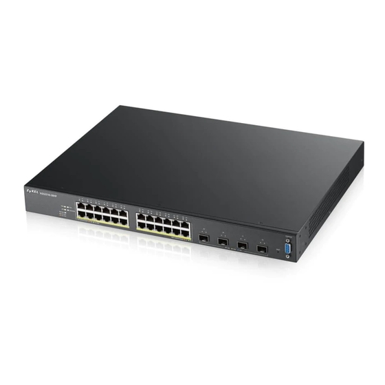
This chapter describes the front panel and rear panel of the Switch and shows you how to make the hardware connections. 3.1 Front Panel The following figures show the front panels of the Switch. Figure 7 Front Panel: XGS2210-28 Figure 8 Front Panel: XGS2210-28HP Figure 9 Front Panel: XGS2210-52 Figure 10 Front Panel: XGS2210-52HP 3.1.1 Gigabit Ethernet Ports... -
Page 29: Sfp/Sfp+ Slots
Chapter 3 Hardware Panels on the cable and using half duplex mode. When the Switch’s auto-negotiation is turned off, an Ethernet port uses the pre-configured speed and duplex mode when making a connection, thus requiring you to make sure that the settings of the peer Ethernet port are the same in order to connect. 3.1.1.1 Default Ethernet Negotiation Settings The factory default negotiation settings for the Gigabit ports on the Switch are: •... -
Page 30: Transceiver Removal
Chapter 3 Hardware Panels Figure 11 Transceiver Installation Example Figure 12 Connecting the Fiber Optic Cables 3.1.2.2 Transceiver Removal Use the following steps to remove a mini-GBIC transceiver (SFP module). Remove the fiber optic cables from the transceiver. Open the transceiver’s latch (latch styles vary). Pull the transceiver out of the slot. -
Page 31: Rear Panel
Chapter 3 Hardware Panels 3.2 Rear Panel The following figures show the rear panels of the Switch. Figure 16 Rear Panel: XGS2210-28 Figure 17 Rear Panel: XGS2210-28HP Figure 18 Rear Panel: XGS2210-52 Figure 19 Rear Panel: XGS2210-52HP 3.2.1 Console Port... -
Page 32: Leds
Chapter 3 Hardware Panels 3.3 LEDs After you connect the power to the Switch, view the LEDs to ensure proper functioning of the Switch and as an aid in troubleshooting. Table 4 LED Descriptions COLOR STATUS DESCRIPTION Green The system is receiving power from the power module in the power slot. The Switch is acting as a non-master member in a stack or it is in standalone mode. - Page 33 Chapter 3 Hardware Panels Table 4 LED Descriptions (continued) COLOR STATUS DESCRIPTION 49-52 LNK/ACT Green The port has a successful 1000 Mbps connection. Blinking The port is transmitting or receiving data at 1000 Mbps. Blue The port has a successful 10 Gbps connection. Blinking The port is transmitting or receiving data at 10 Gbps.
-
Page 34: Technical Reference
Technical Reference... -
Page 35: The Web Configurator
H A P T E R The Web Configurator 4.1 Overview This section introduces the configuration and functions of the web configurator. The web configurator is an HTML-based management interface that allows easy Switch setup and management via Internet browser. Use Internet Explorer 9.0 and later versions, Mozilla Firefox 21 and later versions, Safari 6.0 and later versions or Google Chrome 26.0 and later versions. - Page 36 Chapter 4 The Web Configurator Figure 20 Web Configurator: Login Click Log In to view the first web configurator screen. If you didn’t change the default administrator password and/or SNMP community values, a warning screen displays each time you log into the web configurator. Click Password / SNMP to open a screen where you can change the administrator and SNMP passwords simultaneously.
-
Page 37: The Status Screen
Chapter 4 The Web Configurator Change the default administrator and/or SNMP passwords, and then click Apply to save your changes. Table 5 Web Configurator: Password/SNMP LABEL DESCRIPTION Administrator This is the default administrator account with the “admin” user name. You cannot change the default administrator user name. - Page 38 Chapter 4 The Web Configurator Figure 23 Web Configurator Home Screen for PoE model(s) (Status) A - Click the menu items to open submenu links, and then click on a submenu link to open the screen in the main window. B, C, D, E, F - These are quick links which allow you to perform certain tasks no matter which screen you are currently working in.
- Page 39 Chapter 4 The Web Configurator Table 6 Navigation Panel Sub-links Overview BASIC SETTING ADVANCED APPLICATION IP APPLICATION MANAGEMENT The following table describes the links in the navigation panel. Table 7 Navigation Panel Links LINK DESCRIPTION Basic Settings System Info This link takes you to a screen that displays general system information. General Setup This link takes you to a screen where you can configure general identification information about the Switch.
- Page 40 Chapter 4 The Web Configurator Table 7 Navigation Panel Links (continued) LINK DESCRIPTION This link takes you to a screen where you can configure DNS (domain name server) IP addresses. Advanced Application VLAN This link takes you to screens where you can configure port-based or 802.1Q VLAN (depending on what you configured in the Switch Setup menu).
- Page 41 Chapter 4 The Web Configurator Table 7 Navigation Panel Links (continued) LINK DESCRIPTION MAC Pinning This link takes you to a screen where you can set specific ports to have priority over other ports in MAC address learning. Private VLAN This link takes you to a screen where you can configure private VLANs.
-
Page 42: Change Your Password
Chapter 4 The Web Configurator 4.3.1 Change Your Password After you log in for the first time, it is recommended you change the default administrator password. Click Management > Access Control > Logins to display the next screen. Figure 24 Change Administrator Login Password 4.4 Saving Your Configuration When you are done modifying the settings in a screen, click Apply to save your changes back to the run-time memory. -
Page 43: Resetting The Switch
Forget the password and/or IP address. Prevent all services from accessing the Switch. Change a service port number but forget it. Note: Be careful not to lock yourself and others out of the Switch. 4.6 Resetting the Switch If you lock yourself (and others) from the Switch or forget the administrator password, you will need to reload the factory-default configuration file or reset the Switch back to the factory defaults. -
Page 44: Help
Chapter 4 The Web Configurator Figure 25 Web Configurator: Logout Screen 4.8 Help The web configurator’s online help has descriptions of individual screens and some supplementary information. Click the Help link from a web configurator screen to view an online help description of that screen. XGS2210 Series User’s Guide... -
Page 45: Initial Setup Example
Chapter 5 Initial Setup Example H A P T E R Initial Setup Example 5.1 Overview This chapter shows how to set up the Switch for an example network. The following lists the configuration steps for the initial setup: • Create a VLAN •... -
Page 46: Setting Port Vid
Chapter 5 Initial Setup Example In the Static VLAN screen, select ACTIVE, enter a descriptive name in the Name field, enter 2 in the VLAN Group ID field for the VLAN2 network, and use the default VLAN type, Normal, in the VLAN Type field. -
Page 47: Configuring Switch Management Ip Address
Figure 27 Initial Setup Network Example: Port VID Click Advanced Applications > VLAN > VLAN Configuration in the navigation panel. Then click the VLAN Port Setup link. Enter 2 in the PVID field for port 2 and click Apply to save your changes back to the run-time memory. - Page 48 Chapter 5 Initial Setup Example Figure 28 Initial Setup Example: Management IP Address Connect your computer to any Ethernet port on the Switch. Make sure your computer is in the same subnet as the Switch. Open your web browser and enter 192.168.1.1 (the default IP address) in the address bar to access the web configurator.
-
Page 49: Tutorials
Chapter 6 Tutorials H A P T E R Tutorials 6.1 Overview This chapter provides some examples of using the web configurator to set up and use the Switch. The tutorials include: • How to Use DHCPv4 Snooping on the Switch •... - Page 50 Chapter 6 Tutorials Access the Switch through http://192.168.1.1 by default. Log into the Switch by entering the username (default: admin) and password (default: 1234). Go to Advanced Application > VLAN > VLAN Configuration > Static VLAN Setup, and create a VLAN with ID of 100.
- Page 51 Chapter 6 Tutorials Figure 31 Tutorial: Tag Untagged Frames Go to Advanced Application > IP Source Guard > IPv4 Source Guard Setup > DHCP Snooping > Configure, activate and specify VLAN 100 as the DHCP VLAN as shown. Click Apply. Figure 32 Tutorial: Specify DHCP VLAN XGS2210 Series User’s Guide...
- Page 52 Chapter 6 Tutorials Click the Port link at the top right corner. The DHCP Snooping Port Configure screen appears. Select Trusted in the Server Trusted state field for port 5 because the DHCP server is connected to port 5. Keep ports 6 and 7 Untrusted because they are connected to DHCP clients.
-
Page 53: How To Use Dhcpv4 Relay On The Switch
Chapter 6 Tutorials Connect your DHCP server to port 5 and a computer (as DHCP client) to either port 6 or 7. The computer should be able to get an IP address from the DHCP server. If you put the DHCP server on port 6 or 7, the computer will not able to get an IP address. -
Page 54: Creating A Vlan
Chapter 6 Tutorials 6.3.2 Creating a VLAN Follow the steps below to configure port 2 as a member of VLAN 102. Access the web configurator through the Switch’s management port. Go to Basic Setting > Switch Setup and set the VLAN type to 802.1Q. Click Apply to save the settings to the run-time memory. - Page 55 Chapter 6 Tutorials Figure 38 Tutorial: Create a Static VLAN Click the VLAN Configuration link in the Static VLAN Setup screen and then the VLAN Port Setup link in the VLAN Configuration screen. Figure 39 Tutorial: Click the VLAN Port Setting Link Enter 102 in the PVID field for port 2 to add a tag to incoming untagged frames received on that port so that the frames are forwarded to the VLAN group that the tag defines.
-
Page 56: Configuring Dhcpv4 Relay
Figure 40 Tutorial: Add Tag for Frames Received on Port 2 11 Click the Save link in the upper right corner of the web configurator to save your configuration permanently. 6.3.3 Configuring DHCPv4 Relay Follow the steps below to enable DHCP relay on the Switch and allow the Switch to add relay agent information (such as the VLAN ID) to DHCP requests. -
Page 57: Troubleshooting
Chapter 6 Tutorials Figure 41 Tutorial: Set DHCP Server and Relay Information Click the Save link in the upper right corner of the web configurator to save your configuration permanently. The DHCP server can then assign a specific IP address based on the DHCP request. 6.3.4 Troubleshooting Check the client A’s IP address. -
Page 58: Status And Zon
Chapter 7 Status and ZON H A P T E R Status and ZON 7.1 Overview This chapter describes the screens for System Status, ZON Utility, ZON Neighbor Management, Port Status, and Port Details. 7.1.1 What You Can Do • Use the Status screen (Section 7.2 on page 58) to see the Switch’s general device information, system status, and IP addresses. - Page 59 Chapter 7 Status and ZON Figure 42 Status (for PoE model(s)) The following table describes the labels in this screen. Table 9 Status LABEL DESCRIPTION Device Information Device Type This field displays the model name of this Switch. System Name This field displays the name used to identify the Switch on any network.
-
Page 60: Zyxel One Network (Zon) Utility Screen
Chapter 7 Status and ZON Table 9 Status (continued) LABEL DESCRIPTION IP Address Information IPv4 Address This field displays the Switch’s current IPv4 address. Subnet Mask This field displays the Switch’s subnet mask. Default This field displays the IP address of the Switch’s default gateway. Gateway IP Setup Click the link to go to the Basic Setting >... -
Page 61: Zon Neighbor Management Screen
Chapter 7 Status and ZON Figure 43 ZON Utility Screen 7.4 ZON Neighbor Management Screen The ZON neighbor management screen allows you to view and manage the Switch’s neighboring devices more conveniently. It uses Layer Link Discovery Protocol (LLDP) to discover all neighbor devices connected to the Switch including non-Zyxel devices. - Page 62 Chapter 7 Status and ZON The following table describes the fields in the above screen. Table 10 Status > Neighbor LABEL DESCRIPTION Local Port This shows the port of the Switch, on which the neighboring device is discovered. Desc. This shows the port description of the Switch. PoE Draw This shows the consumption that the neighboring device connected to this port draws from the Switch.
-
Page 63: Basic Setting
Chapter 8 Basic Setting H A P T E R Basic Setting 8.1 Overview This chapter describes how to configure the System Info, General Setup, Switch Setup, IP Setup, Port Setup, PoE, Interface Setup and IPv6 screens. 8.1.1 What You Can Do •... - Page 64 Chapter 8 Basic Setting Figure 45 Basic Setting > System Info (for PoE model(s) only) (Standalone mode) Figure 46 Basic Setting > System Info (for PoE model(s) only) (Stacking mode) XGS2210 Series User’s Guide...
- Page 65 Chapter 8 Basic Setting The following table describes the labels in this screen. Table 11 Basic Setting > System Info (Standalone and Stacking Modes) LABEL DESCRIPTION System Name This field displays the descriptive name of the Switch for identification purposes. Product Model This field displays the product model of the Switch.
-
Page 66: System Information Stacking Hardware Monitor
Chapter 8 Basic Setting Table 11 Basic Setting > System Info (Standalone and Stacking Modes) (continued) LABEL DESCRIPTION Status Normal indicates that the voltage is within an acceptable operating range at this point; otherwise Error is displayed. Hardware Status (Stacking Mode) Slot This number identifies the Switch in the stack. -
Page 67: General Setup
Chapter 8 Basic Setting Table 12 Basic Setting > System Info > Hardware Monitor (Stacking Mode) (continued) LABEL DESCRIPTION Threshold This field displays the upper temperature limit at this sensor. Status This field displays Normal for temperatures below the threshold and Error for those above. Fan Speed (RPM) A properly functioning fan is an essential component (along with a sufficiently ventilated, cool operating environment) in order for the device to stay within the temperature threshold. - Page 68 Figure 48 Basic Setting > General Setup The following table describes the labels in this screen. Table 13 Basic Setting > General Setup LABEL DESCRIPTION System Name Choose a descriptive name for identification purposes. This name consists of up to 64 printable characters;...
-
Page 69: Introduction To Vlans
Chapter 8 Basic Setting Table 13 Basic Setting > General Setup (continued) LABEL DESCRIPTION Daylight Saving Daylight saving is a period from late spring to early fall when many countries set their clocks Time ahead of normal local time by one hour to give more daytime light in the evening. Select this option if you use Daylight Saving Time. -
Page 70: Switch Setup
Chapter 8 Basic Setting 8.5 Switch Setup Click Basic Setting > Switch Setup in the navigation panel to display the screen as shown. The VLAN setup screens change depending on whether you choose 802.1Q or Port Based in the VLAN Type field in this screen. -
Page 71: Ip Setup
Chapter 8 Basic Setting Table 14 Basic Setting > Switch Setup (continued) LABEL DESCRIPTION Leave Timer Leave Time sets the duration of the Leave Period timer for GVRP in milliseconds. Each port has a single Leave Period timer. Leave Time must be two times larger than Join Timer; the default is 600 milliseconds. -
Page 72: Ip Status Details
Chapter 8 Basic Setting Note: You must configure a VLAN first. Each VLAN can have multiple management IP addresses, and you can log into the Switch via different management IP addresses simultaneously. Figure 50 Basic Setting > IP Setup The following table describes the labels in this screen. Table 15 Basic Setting >... -
Page 73: Ip Configuration
Chapter 8 Basic Setting Figure 52 Basic Setting > IP Setup > IP Status Details: DHCP The following table describes the labels in this screen. Table 17 Basic Setting > IP Setup > IP Status Details: DHCP LABEL DESCRIPTION Type This shows whether this IP address is dynamically assigned from a DHCP server or manually assigned (Static or DHCP). - Page 74 Chapter 8 Basic Setting Figure 53 Basic Setting > IP Setup > IP Configuration The following table describes the labels in this screen. Table 18 Basic Setting > IP Setup > IP Configuration LABEL DESCRIPTION Default Type the IP address of the default outgoing gateway in dotted decimal notation, for example Gateway 192.168.1.254.
-
Page 75: Port Setup
Chapter 8 Basic Setting Table 18 Basic Setting > IP Setup > IP Configuration (continued) LABEL DESCRIPTION Type This field displays the type of IP address status. Select an entry’s check box to select a specific entry. Otherwise, select the check box in the table heading row to select all entries. - Page 76 Chapter 8 Basic Setting Figure 55 Basic Setting > Port Setup (Stacking mode) The following table describes the labels in this screen. Table 19 Basic Setting > Port Setup LABEL DESCRIPTION Slot (Stacking This field appears only in stacking mode. Click the drop-down list to choose the slot number of the mode) Switch in a stack.
-
Page 77: Poe Status
Chapter 8 Basic Setting Table 19 Basic Setting > Port Setup (continued) LABEL DESCRIPTION Speed/Duplex Select the speed and the duplex mode of the Ethernet connection on this port. Choices are Auto-1000M, 10M/Half Duplex, 10M/Full Duplex, 100M/Half Duplex, 100M/Full Duplex and 1000M/ Full Duplex (Gigabit connections only). - Page 78 Chapter 8 Basic Setting A powered device (PD) is a device such as an access point or a switch, that supports PoE (Power over Ethernet) so that it can receive power from another device through an Ethernet port. In the figure below, the IP camera and IP phone get their power directly from the Switch. Aside from minimizing the need for cables and wires, PoE removes the hassle of trying to find a nearby electric outlet to power up devices.
- Page 79 Chapter 8 Basic Setting Figure 58 Basic Setting > PoE Setup (Stacking mode) The following table describes the labels in this screen. Table 20 Basic Setting > PoE Status LABEL DESCRIPTION PoE Status Slot (Stacking This field appears only in stacking mode. Click the drop-down list to choose the slot number of mode) the Switch in a stack.
-
Page 80: Poe Time Range Status
Chapter 8 Basic Setting Table 20 Basic Setting > PoE Status (continued) LABEL DESCRIPTION State This field shows which ports can receive power from the Switch. You can set this in Section 8.8.2 on page • Disable - The PD connected to this port cannot get power supply. •... -
Page 81: Poe Setup
Chapter 8 Basic Setting Figure 60 Basic Setting > PoE Setup > PoE Time Range Status (Stacking mode) The following table describes the labels in this screen. Table 21 Basic Setting > PoE Setup > PoE Time Range Status LABEL DESCRIPTION Slot (Stacking This field appears only in stacking mode. - Page 82 Chapter 8 Basic Setting Figure 61 Basic Setting > PoE Setup (Standalone mode) XGS2210 Series User’s Guide...
- Page 83 Chapter 8 Basic Setting Figure 62 Basic Setting > PoE Setup (Stacking mode) The following table describes the labels in this screen. Table 22 Basic Setting > PoE Setup LABEL DESCRIPTION PoE Mode Select the power management mode you want the Switch to use. •...
- Page 84 Chapter 8 Basic Setting Table 22 Basic Setting > PoE Setup (continued) LABEL DESCRIPTION Settings in this row apply to all ports. Use this row only if you want to make some settings the same for all ports. Use this row first to set the common settings and then make adjustments on a port-by-port basis.
-
Page 85: Interface Setup
Chapter 8 Basic Setting 8.9 Interface Setup An IPv6 address is configured on a per-interface basis. The interface can be a physical interface (for example, an Ethernet port) or a virtual interface (for example, a VLAN). The Switch supports the VLAN interface type for IPv6 at the time of writing. -
Page 86: Ipv6
Chapter 8 Basic Setting 8.10 IPv6 Use this screen to view the IPv6 interface status and configure Switch’s management IPv6 addresses. Click Basic Setting > IPv6 in the navigation panel to display the IPv6 status screen as shown next. Figure 64 Basic Setting > IPv6 The following table describes the labels in this screen. - Page 87 Chapter 8 Basic Setting Figure 65 Basic Setting > IPv6 > IPv6 Interface Status The following table describes the labels in this screen. Table 25 Basic Setting > IPv6 > IPv6 Interface Status LABEL DESCRIPTION IPv6 Active This field displays whether the IPv6 interface is activated or not. MTU Size This field displays the Maximum Transmission Unit (MTU) size for IPv6 packets on this interface.
-
Page 88: Ipv6 Configuration
Chapter 8 Basic Setting Table 25 Basic Setting > IPv6 > IPv6 Interface Status (continued) LABEL DESCRIPTION Number of This field displays the number of consecutive neighbor solicitations the Switch sends for this DAD Attempts interface. NS-Interval This field displays the time interval (in milliseconds) at which neighbor solicitations are re-sent for (millisecond) this interface. -
Page 89: Ipv6 Global Setup
Chapter 8 Basic Setting Figure 66 Basic Setting > IPv6 > IPv6 Configuration The following table describes the labels in this screen. Table 26 Basic Setting > IPv6 > IPv6 Configuration LABEL DESCRIPTION IPv6 Global Click the link to go to a screen where you can configure the global IPv6 settings on the Switch. Setup IPv6 Interface Click the link to go to a screen where you can enable an IPv6 interface on the Switch. -
Page 90: Ipv6 Interface Setup
Chapter 8 Basic Setting Figure 67 Basic Setting > IPv6 > IPv6 Configuration > IPv6 Global Setup The following table describes the labels in this screen. Table 27 Basic Setting > IPv6 > IPv6 Configuration > IPv6 Global Setup LABEL DESCRIPTION IPv6 Hop Limit Specify the maximum number of hops (from 1 to 255) in router advertisements. -
Page 91: Ipv6 Link-Local Address Setup
Chapter 8 Basic Setting Table 28 Basic Setting > IPv6 > IPv6 Configuration > IPv6 Interface Setup (continued) LABEL DESCRIPTION Apply Click Apply to save your changes to the Switch’s run-time memory. The Switch loses these changes if it is turned off or loses power, so use the Save link on the top navigation panel to save your changes to the nonvolatile memory when you are done configuring. -
Page 92: Ipv6 Global Address Setup
Chapter 8 Basic Setting Table 29 Basic Setting > IPv6 > IPv6 Configuration > IPv6 Link-Local Address Setup (continued) LABEL DESCRIPTION IPv6 Link-Local This is the static IPv6 link-local address for the interface. Address IPv6 Default This is the default gateway IPv6 address for the interface. Gateway 8.10.6 IPv6 Global Address Setup Use this screen to configure the interface’s IPv6 global address. -
Page 93: Ipv6 Neighbor Discovery Setup
Chapter 8 Basic Setting Table 30 Basic Setting > IPv6 > IPv6 Configuration > IPv6 Global Address Setup (continued) LABEL DESCRIPTION Delete Check the entry(ies) that you want to remove and then click Delete to remove the selected entry(ies) from the summary table. Cancel Click Cancel to clear the check boxes. -
Page 94: Ipv6 Router Discovery Setup
Chapter 8 Basic Setting Table 31 Basic Setting > IPv6 > IPv6 Configuration > IPv6 Neighbor Discovery Setup (continued) LABEL DESCRIPTION NS Interval This field displays the time interval (in milliseconds) at which neighbor solicitations are re-sent for this interface. Reachable This field displays how long (in milliseconds) a neighbor is considered reachable for this interface. -
Page 95: Ipv6 Prefix Setup
Chapter 8 Basic Setting Table 32 Basic Setting > IPv6 > IPv6 Configuration > IPv6 Router Discovery Setup (continued) LABEL DESCRIPTION Suppress Select this option to set the Switch to not send router advertisements and responses to router solicitations on this interface. Apply Click Apply to save your changes to the Switch’s run-time memory. -
Page 96: Ipv6 Neighbor Setup
Chapter 8 Basic Setting The following table describes the labels in this screen. Table 33 Basic Setting > IPv6 > IPv6 Configuration > IPv6 Prefix Setup LABEL DESCRIPTION Interface Select the IPv6 interface you want to configure. Prefix Set the IPv6 prefix that the Switch includes in router advertisements for this interface. Prefix Length Set the prefix length that the Switch includes in router advertisements for this interface. - Page 97 Chapter 8 Basic Setting Figure 74 Basic Setting > IPv6 > IPv6 Configuration > IPv6 Neighbor Setup The following table describes the labels in this screen. Table 34 Basic Setting > IPv6 > IPv6 Configuration > IPv6 Neighbor Setup LABEL DESCRIPTION Interface Type Select the type of IPv6 interface for which you want to configure.
-
Page 98: Dhcpv6 Client Setup
Chapter 8 Basic Setting 8.10.11 DHCPv6 Client Setup Use this screen to configure the Switch’s DHCP settings when it is acting as a DHCPv6 client. Click the link next to DHCPv6 Client Setup in the IPv6 Configuration screen to display the screen as shown next. Figure 75 Basic Setting >... -
Page 99: Stacking
The last two SFP ports of your Switch are dedicated for Switch stacking. These are the Switches that support stacking at the time of writing. Table 36 Switch Stacking MODELS WITH STACKING SUPPORT XGS2210-28 XGS2210-28HP XGS2210-52 XGS2210-52HP Note: Up to 2 Switches per stack are allowed. -
Page 100: Stacking Status
Chapter 8 Basic Setting Figure 77 Stacking Topology 8.11.1 Stacking Status Click Basic Setting > Stacking in the navigation panel to display the Stacking Status screen as shown next. Figure 78 Basic Setting > Stacking Status The following table describes the labels in this screen. Table 37 Basic Setting >... -
Page 101: Stacking Slot
Chapter 8 Basic Setting Table 37 Basic Setting > Stacking > Stacking Status (continued) LABEL DESCRIPTION Neighbor This field displays the neighbor Switch that is connected to slot channel 2 of the Switch. Speed This field displays the Ethernet speed of stacking channel 2 of the Switch. 8.11.2 Stacking Slot Click Basic Setting >... -
Page 102: Stacking Configuration
Chapter 8 Basic Setting Table 38 Basic Setting > Stacking > Stacking Status > Slot number (continued) LABEL DESCRIPTION Stacking This field displays the status of the port stacking channel 2 of the Switch. It will display up for Channel 2 active or down for inactive. - Page 103 Chapter 8 Basic Setting Use the following procedure to create a stack: Select a Switch to be the master. Change its mode to stacking mode. You will see a message asking you to confirm the change. Click OK to confirm and the Switch will reboot automatically using a new config01.
-
Page 104: Dns
Chapter 8 Basic Setting The following table describes the labels in this screen. Table 39 Basic Setting > Stacking > Configuration LABEL DESCRIPTION Active Select the Active check box to put the Switch in stacking mode. This will erase the running configuration, config01 and config02. - Page 105 Chapter 8 Basic Setting Table 40 Basic Setting > DNS (continued) LABEL DESCRIPTION Server Address Enter a domain name server IPv6/IPv4 address in order to be able to use a domain name instead of an IP address. Apply Click Apply to save your changes to the Switch’s run-time memory. The Switch loses these changes if it is turned off or loses power, so use the Save link on the top navigation panel to save your changes to the nonvolatile memory when you are done configuring.
-
Page 106: Vlan
H A P T E R VLAN 9.1 Overview This chapter shows you how to configure 802.1Q tagged and port-based VLANs. The type of screen you see here depends on the VLAN Type you selected in the Switch Setup screen. 9.1.1 What You Can Do •... -
Page 107: Forwarding Tagged And Untagged Frames
Chapter 9 VLAN The CFI (Canonical Format Indicator) is a single-bit flag, always set to zero for Ethernet switches. If a frame received at an Ethernet port has a CFI set to 1, then that frame should not be forwarded as it is to an untagged port. -
Page 108: Port Vlan Trunking
Chapter 9 VLAN Please refer to the following table for common IEEE 802.1Q VLAN terminology. Table 41 IEEE 802.1Q VLAN Terminology VLAN PARAMETER TERM DESCRIPTION VLAN Type Permanent VLAN This is a static VLAN created manually. Dynamic VLAN This is a VLAN configured by a GVRP registration/deregistration process. -
Page 109: Vlan Status
Chapter 9 VLAN Figure 83 Switch Setup > Select VLAN Type Static VLAN Use a static VLAN to decide whether an incoming frame on a port should be • sent to a VLAN group as normal depending on its VLAN tag. •... -
Page 110: Vlan Details
Chapter 9 VLAN The following table describes the labels in this screen. Table 42 Advanced Application > VLAN: VLAN Status LABEL DESCRIPTION VLAN Search by Enter an existing VLAN ID number(s) (separated by a comma) and click Search to display only the specified VLAN(s) in the list below. - Page 111 Chapter 9 VLAN Figure 86 Advanced Application > VLAN > VLAN Detail (Stacking mode) The following table describes the labels in this screen. Table 43 Advanced Application > VLAN > VLAN Detail LABEL DESCRIPTION VLAN Status Click this to go to the VLAN Status screen. This is the VLAN identification number that was configured in the Static VLAN screen.
-
Page 112: Private Vlan Status
Chapter 9 VLAN 9.3 Private VLAN Status Use this screen to view all private VLANs created on the Switch. Click Advanced Application > VLAN > Private VLAN Status to see the following screen. Figure 87 Advanced Application > VLAN > Private VLAN Status The following table describes the labels in this screen. -
Page 113: Configure A Static Vlan
Chapter 9 VLAN Figure 88 Advanced Application > VLAN > VLAN Configuration The following table describes the labels in the above screen. Table 45 Advanced Application > VLAN > VLAN Configuration LABEL DESCRIPTION Static VLAN Setup Click Click Here to configure the Static VLAN for the Switch. VLAN Port Setup Click Click Here to configure the VLAN Port for the Switch. - Page 114 Chapter 9 VLAN Figure 89 Advanced Application > VLAN > VLAN Configuration > Static VLAN Setup (Standalone Mode) XGS2210 Series User’s Guide...
- Page 115 Chapter 9 VLAN Figure 90 Advanced Application > VLAN > VLAN Configuration > Static VLAN Setup (Stacking Mode) The following table describes the related labels in this screen. Table 46 Advanced Application > VLAN > VLAN Configuration > Static VLAN Setup LABEL DESCRIPTION ACTIVE...
-
Page 116: Configure Vlan Port Settings
Chapter 9 VLAN Table 46 Advanced Application > VLAN > VLAN Configuration > Static VLAN Setup (continued) LABEL DESCRIPTION Port The port number identifies the port you are configuring. In stacking mode, the first number represents the slot and the second the port number. Settings in this row apply to all ports. - Page 117 Chapter 9 VLAN Figure 91 Advanced Application > VLAN > VLAN Configuration > VLAN Port Setup (Standalone mode) Figure 92 Advanced Application > VLAN > VLAN Configuration > VLAN Port Setup (Stacking mode) XGS2210 Series User’s Guide...
-
Page 118: Subnet Based Vlans
Chapter 9 VLAN The following table describes the labels in this screen. Table 47 Advanced Application > VLAN > VLAN Configuration> VLAN Port Setup LABEL DESCRIPTION GVRP GVRP (GARP VLAN Registration Protocol) is a registration protocol that defines a way for switches to register necessary VLAN members on ports across the network. -
Page 119: Configuring Subnet Based Vlan
Chapter 9 VLAN For example, an ISP (Internet Services Provider) may divide different types of services it provides to customers into different IP subnets. Traffic for voice services is designated for IP subnet 172.16.1.0/24, video for 192.168.1.0/24 and data for 10.1.1.0/24. The Switch can then be configured to group incoming traffic based on the source IP subnet of incoming frames. - Page 120 Chapter 9 VLAN Figure 94 Advanced Application > VLAN > VLAN Configuration > Subnet Based VLAN Setup The following table describes the labels in this screen. Table 48 Advanced Application > VLAN > VLAN Configuration > Subnet Based VLAN Setup LABEL DESCRIPTION Active...
-
Page 121: Protocol Based Vlans
Chapter 9 VLAN Table 48 Advanced Application > VLAN > VLAN Configuration > Subnet Based VLAN Setup LABEL DESCRIPTION Active This field shows whether the subnet based VLAN is active or not. Name This field shows the name the subnet based VLAN. This field shows the IP address of the subnet for this subnet based VLAN. - Page 122 Chapter 9 VLAN Note: Protocol-based VLAN applies to un-tagged packets and is applicable only when you use IEEE 802.1Q tagged VLAN. Figure 96 Advanced Application > VLAN > VLAN Configuration > Protocol Based VLAN Setup (Standalone mode) Figure 97 Advanced Application > VLAN > VLAN Configuration > Protocol Based VLAN Setup (Stacking mode) The following table describes the labels in this screen.
-
Page 123: Voice Vlan
Chapter 9 VLAN Table 49 Advanced Application > VLAN > VLAN Configuration > Protocol Based VLAN Setup LABEL DESCRIPTION Ethernet-type Use the drop down list box to select a predefined protocol to be included in this protocol based VLAN or select Others and type the protocol number in hexadecimal notation. For example the IP protocol in hexadecimal notation is 0800, and Novell IPX protocol is 8137. - Page 124 Chapter 9 VLAN Figure 98 Advanced Application > VLAN > VLAN Configuration > Voice VLAN Setup The following table describes the fields in the above screen. Table 50 Advanced Application > VLAN > VLAN Configuration > Voice VLAN Setup LABEL DESCRIPTION Voice VLAN Global Setup Voice VLAN...
-
Page 125: Mac Based Vlan
Chapter 9 VLAN Table 50 Advanced Application > VLAN > VLAN Configuration > Voice VLAN Setup LABEL DESCRIPTION Select an entry’s check box to select a specific entry. Otherwise, select the check box in the table heading row to select all entries. Delete Click Delete to remove the selected entry from the summary table. -
Page 126: Port-Based Vlan Setup
Chapter 9 VLAN Table 51 Advanced Application > VLAN > VLAN Configuration > MAC Based VLAN Setup LABEL DESCRIPTION Index This field displays the index number of the MAC-based VLAN entry. Name This field displays the name of the MAC-based VLAN entry. MAC Address This field displays the source MAC address that is bind to the MAC-based VLAN entry. - Page 127 Chapter 9 VLAN Figure 100 Advanced Application > VLAN: Port Based VLAN Setup (All Connected) XGS2210 Series User’s Guide...
- Page 128 Chapter 9 VLAN Figure 101 Advanced Application > VLAN: Port Based VLAN Setup (Port Isolation) The following table describes the labels in this screen. Table 52 Advanced Application > VLAN: Port Based VLAN Setup label Description Setting Wizard Choose All connected or Port isolation. All connected means all ports can communicate with each other, that is, there are no virtual LANs.
-
Page 129: Technical Reference
Chapter 9 VLAN Table 52 Advanced Application > VLAN: Port Based VLAN Setup (continued) label Description Outgoing These are the egress ports; an egress port is an outgoing port, that is, a port through which a data packet leaves. If you wish to allow two subscriber ports to talk to each other, you must define the egress port for both ports. - Page 130 Chapter 9 VLAN Figure 102 Protocol Based VLAN Configuration Example To add more ports to this protocol based VLAN. Click the index number of the protocol based VLAN entry. Click 1. Change the value in the Port field to the next port you want to add. Click Add.
-
Page 131: Static Mac Forward Setup
Chapter 10 Static MAC Forward Setup H A P T E R Static MAC Forward Setup 10.1 Overview This chapter discusses how to configure forwarding rules based on MAC addresses of devices on your network. Use these screens to configure static MAC address forwarding. 10.1.1 What You Can Do Use the Static MAC Forwarding screen (Section 10.2 on page... - Page 132 Figure 103 Advanced Application > Static MAC Forwarding (Standalone mode) Figure 104 Advanced Application > Static MAC Forwarding (Stacking mode) The following table describes the labels in this screen. Table 53 Advanced Application > Static MAC Forwarding LABEL DESCRIPTION Active Select this check box to activate your rule.
- Page 133 Chapter 10 Static MAC Forward Setup Table 53 Advanced Application > Static MAC Forwarding (continued) LABEL DESCRIPTION Index Click an index number to modify a static MAC address rule for a port. Active This field displays whether this static MAC address forwarding rule is active (Yes) or not (No). You may temporarily deactivate a rule without deleting it.
-
Page 134: Static Multicast Forward Setup
Chapter 11 Static Multicast Forward Setup H A P T E R Static Multicast Forward Setup 11.1 Static Multicast Forward Setup Overview This chapter discusses how to configure forwarding rules based on multicast MAC addresses of devices on your network. Use these screens to configure static multicast address forwarding. -
Page 135: Configuring Static Multicast Forwarding
Figure 105 No Static Multicast Forwarding Figure 106 Static Multicast Forwarding to A Single Port Figure 107 Static Multicast Forwarding to Multiple Ports 11.2 Configuring Static Multicast Forwarding Use this screen to configure rules to forward specific multicast frames, such as streaming or control frames, to specific port(s). - Page 136 Chapter 11 Static Multicast Forward Setup Figure 108 Advanced Application > Static Multicast Forwarding The following table describes the labels in this screen. Table 54 Advanced Application > Static Multicast Forwarding LABEL DESCRIPTION Active Select this check box to activate your rule. You may temporarily deactivate a rule without deleting it by clearing this check box.
- Page 137 Chapter 11 Static Multicast Forward Setup Table 54 Advanced Application > Static Multicast Forwarding (continued) LABEL DESCRIPTION Select an entry’s check box to select a specific entry. Otherwise, select the check box in the table heading row to select all entries. Delete Click Delete to remove the selected entry from the summary table.
-
Page 138: Filtering
H A P T E R Filtering 12.1 Filtering Overview This chapter discusses MAC address port filtering. Filtering means sifting traffic going through the Switch based on the source and/or destination MAC addresses and VLAN group (ID). 12.1.1 What You Can Do Use the Filtering screen (Section 12.2 on page 138) to create rules for traffic going through the Switch. - Page 139 Chapter 12 Filtering The following table describes the related labels in this screen. Table 55 Advanced Application > Filtering LABEL DESCRIPTION Active Make sure to select this check box to activate your rule. You may temporarily deactivate a rule without deleting it by deselecting this check box. Name Type a descriptive name (up to 32 printable ASCII characters) for this rule.
-
Page 140: Spanning Tree Protocol
H A P T E R Spanning Tree Protocol 13.1 Spanning Tree Protocol Overview The Switch supports Spanning Tree Protocol (STP), Rapid Spanning Tree Protocol (RSTP) and Multiple Spanning Tree Protocol (MSTP) as defined in the following standards. • IEEE 802.1D Spanning Tree Protocol •... -
Page 141: Stp Terminology
Chapter 13 Spanning Tree Protocol change first notifies the root bridge that then notifies the network. Both RSTP and STP flush unwanted learned addresses from the filtering database. In RSTP, the port states are Discarding, Learning, and Forwarding. Note: In this user’s guide, “STP” refers to both STP and RSTP. STP Terminology The root bridge is the base of the spanning tree. -
Page 142: Multiple Rstp
Chapter 13 Spanning Tree Protocol STP Port States STP assigns five port states to eliminate packet looping. A bridge port is not allowed to go directly from blocking state to forwarding state so as to eliminate transient loops. Table 57 STP Port States PORT STATE DESCRIPTION Disabled... -
Page 143: Spanning Tree Protocol Status Screen
Chapter 13 Spanning Tree Protocol 13.2 Spanning Tree Protocol Status Screen The Spanning Tree Protocol status screen changes depending on what standard you choose to implement on your network. Click Advanced Application > Spanning Tree Protocol to see the screen as shown. -
Page 144: Configure Rapid Spanning Tree Protocol
Chapter 13 Spanning Tree Protocol Figure 113 Advanced Application > Spanning Tree Protocol > Configuration The following table describes the labels in this screen. Table 58 Advanced Application > Spanning Tree Protocol > Configuration LABEL DESCRIPTION Spanning Tree You can activate one of the STP modes on the Switch. Mode Select Rapid Spanning Tree, Multiple Rapid Spanning Tree or Multiple Spanning Tree. - Page 145 Chapter 13 Spanning Tree Protocol Figure 114 Advanced Application > Spanning Tree Protocol > RSTP (Standalone mode) XGS2210 Series User’s Guide...
- Page 146 Chapter 13 Spanning Tree Protocol Figure 115 Advanced Application > Spanning Tree Protocol > RSTP (Stacking mode) The following table describes the labels in this screen. Table 59 Advanced Application > Spanning Tree Protocol > RSTP LABEL DESCRIPTION Status Click Status to display the RSTP Status screen (see Figure 116 on page 148).
- Page 147 Chapter 13 Spanning Tree Protocol Table 59 Advanced Application > Spanning Tree Protocol > RSTP (continued) LABEL DESCRIPTION Max Age This is the maximum time (in seconds) the Switch can wait without receiving a BPDU before attempting to reconfigure. All Switch ports (except for designated ports) should receive BPDUs at regular intervals.
-
Page 148: Rapid Spanning Tree Protocol Status
Chapter 13 Spanning Tree Protocol 13.5 Rapid Spanning Tree Protocol Status Click Advanced Application > Spanning Tree Protocol in the navigation panel to display the status screen as shown next. See Section 13.1 on page 140 for more information on RSTP. Note: This screen is only available after you activate RSTP on the Switch. - Page 149 Chapter 13 Spanning Tree Protocol Table 60 Advanced Application > Spanning Tree Protocol > Status: RSTP (continued) LABEL DESCRIPTION Forwarding Delay This is the time (in seconds) the root switch will wait before changing states (that is, listening to (second) learning to forwarding).
-
Page 150: Configure Multiple Rapid Spanning Tree Protocol
Chapter 13 Spanning Tree Protocol 13.6 Configure Multiple Rapid Spanning Tree Protocol To configure MRSTP, click MRSTP in the Advanced Application > Spanning Tree Protocol screen. See Section 13.1 on page 140 for more information on MRSTP. Figure 118 Advanced Application > Spanning Tree Protocol > MRSTP (Standalone mode) XGS2210 Series User’s Guide... - Page 151 Chapter 13 Spanning Tree Protocol Figure 119 Advanced Application > Spanning Tree Protocol > MRSTP (Stacking mode) The following table describes the labels in this screen. Table 61 Advanced Application > Spanning Tree Protocol > MRSTP LABEL DESCRIPTION Status Click Status to display the MRSTP Status screen (see Figure 120 on page 153).
- Page 152 Chapter 13 Spanning Tree Protocol Table 61 Advanced Application > Spanning Tree Protocol > MRSTP (continued) LABEL DESCRIPTION Max Age This is the maximum time (in seconds) the Switch can wait without receiving a BPDU before attempting to reconfigure. All Switch ports (except for designated ports) should receive BPDUs at regular intervals.
-
Page 153: Multiple Rapid Spanning Tree Protocol Status
Chapter 13 Spanning Tree Protocol 13.7 Multiple Rapid Spanning Tree Protocol Status Click Advanced Application > Spanning Tree Protocol in the navigation panel to display the status screen as shown next. See Section 13.1 on page 140 for more information on MRSTP. Note: This screen is only available after you activate MRSTP on the Switch. - Page 154 Chapter 13 Spanning Tree Protocol The following table describes the labels in this screen. Table 62 Advanced Application > Spanning Tree Protocol > Status: MRSTP LABEL DESCRIPTION Configuration Click Configuration to specify which STP mode you want to activate. Click MRSTP to edit MRSTP settings on the Switch.
-
Page 155: Configure Multiple Spanning Tree Protocol
Chapter 13 Spanning Tree Protocol Table 62 Advanced Application > Spanning Tree Protocol > Status: MRSTP (continued) LABEL DESCRIPTION Designated Port ID This field displays the priority and number of the bridge port (on the designated bridge), through which the designated bridge transmits the stored configuration messages. Designated Cost This field displays the path cost to the LAN segment to which the port is connected when the port is a designated port. - Page 156 Chapter 13 Spanning Tree Protocol Figure 122 Advanced Application > Spanning Tree Protocol > MSTP (Standalone mode) XGS2210 Series User’s Guide...
- Page 157 Chapter 13 Spanning Tree Protocol Figure 123 Advanced Application > Spanning Tree Protocol > MSTP (Stacking mode) XGS2210 Series User’s Guide...
- Page 158 Chapter 13 Spanning Tree Protocol The following table describes the labels in this screen. Table 63 Advanced Application > Spanning Tree Protocol > MSTP LABEL DESCRIPTION Port Click Port to display the MSTP Port screen (see Figure 124 on page 160).
-
Page 159: Multiple Spanning Tree Protocol Port Configuration
Chapter 13 Spanning Tree Protocol Table 63 Advanced Application > Spanning Tree Protocol > MSTP (continued) LABEL DESCRIPTION Slot (Stacking This field appears only in stacking mode. Click the drop-down list to choose the slot number of mode) the Switch in a stack. Port (Standalone This field displays the port number. - Page 160 Chapter 13 Spanning Tree Protocol Figure 124 Advanced Application > Spanning Tree Protocol > MSTP > Port (Standalone mode) Figure 125 Advanced Application > Spanning Tree Protocol > MSTP > Port (Stacking mode) XGS2210 Series User’s Guide...
-
Page 161: Multiple Spanning Tree Protocol Status
Chapter 13 Spanning Tree Protocol The following table describes the labels in this screen. Table 64 Advanced Application > Spanning Tree Protocol > MSTP > Port LABEL DESCRIPTION MSTP Click MSTP to edit MSTP settings on the Switch. Slot (Stacking This field appears only in stacking mode. - Page 162 Chapter 13 Spanning Tree Protocol Figure 126 Advanced Application > Spanning Tree Protocol > Status: MSTP (Standalone mode) Figure 127 Advanced Application > Spanning Tree Protocol > Status: MSTP (Stacking mode) XGS2210 Series User’s Guide...
- Page 163 Chapter 13 Spanning Tree Protocol The following table describes the labels in this screen. Table 65 Advanced Application > Spanning Tree Protocol > Status: MSTP LABEL DESCRIPTION Configuration Click Configuration to specify which STP mode you want to activate. Click MSTP to edit MSTP settings on the Switch.
-
Page 164: Technical Reference
Chapter 13 Spanning Tree Protocol Table 65 Advanced Application > Spanning Tree Protocol > Status: MSTP (continued) LABEL DESCRIPTION Port State This field displays the port state in STP. • Discarding - The port does not forward/process received frames or learn MAC addresses, but still listens for BPDUs. -
Page 165: Mst Region
Chapter 13 Spanning Tree Protocol Figure 128 STP/RSTP Network Example With MSTP, VLANs 1 and 2 are mapped to different spanning trees in the network. Thus traffic from the two VLANs travel on different paths. The following figure shows the network example using MSTP. Figure 129 MSTP Network Example 13.10.2 MST Region An MST region is a logical grouping of multiple network devices that appears as a single device to the... -
Page 166: Common And Internal Spanning Tree (Cist)
Chapter 13 Spanning Tree Protocol The following figure shows an example where there are two MST regions. Regions 1 and 2 have 2 spanning tree instances. Figure 130 MSTIs in Different Regions 13.10.4 Common and Internal Spanning Tree (CIST) A CIST represents the connectivity of the entire network and it is equivalent to a spanning tree in an STP/ RSTP. -
Page 167: Bandwidth Control
Chapter 14 Bandwidth Control H A P T E R Bandwidth Control 14.1 Bandwidth Control Overview This chapter shows you how you can cap the maximum bandwidth using the Bandwidth Control screen. Bandwidth control means defining a maximum allowable bandwidth for incoming and/or out-going traffic flows on a port. - Page 168 Figure 132 Advanced Application > Bandwidth Control (Standalone mode) XGS2210 Series User’s Guide...
- Page 169 Chapter 14 Bandwidth Control Figure 133 Advanced Application > Bandwidth Control (Stacking mode) The following table describes the related labels in this screen. Table 66 Advanced Application > Bandwidth Control LABEL DESCRIPTION Active Select this check box to enable bandwidth control on the Switch. Slot (Stacking This field appears only in stacking mode.
- Page 170 Chapter 14 Bandwidth Control Table 66 Advanced Application > Bandwidth Control (continued) LABEL DESCRIPTION Egress Rate Specify the maximum bandwidth allowed in kilobits per second (Kbps) for the out-going traffic flow on a port. Apply Click Apply to save your changes to the Switch’s run-time memory. The Switch loses these changes if it is turned off or loses power, so use the Save link on the top navigation panel to save your changes to the non-volatile memory when you are done configuring.
-
Page 171: Broadcast Storm Control
Chapter 15 Broadcast Storm Control H A P T E R Broadcast Storm Control 15.1 Broadcast Storm Control Overview This chapter introduces and shows you how to configure the broadcast storm control feature. Broadcast storm control limits the number of broadcast, multicast and destination lookup failure (DLF) packets the Switch receives per second on the ports. - Page 172 Figure 134 Advanced Application > Broadcast Storm Control (Standalone mode) XGS2210 Series User’s Guide...
- Page 173 Chapter 15 Broadcast Storm Control Figure 135 Advanced Application > Broadcast Storm Control (Stacking mode) The following table describes the labels in this screen. Table 67 Advanced Application > Broadcast Storm Control LABEL DESCRIPTION Active Select this check box to enable traffic storm control on the Switch. Clear this check box to disable this feature.
- Page 174 Chapter 15 Broadcast Storm Control Table 67 Advanced Application > Broadcast Storm Control (continued) LABEL DESCRIPTION Apply Click Apply to save your changes to the Switch’s run-time memory. The Switch loses these changes if it is turned off or loses power, so use the Save link on the top navigation panel to save your changes to the non-volatile memory when you are done configuring.
-
Page 175: Mirroring
Chapter 16 Mirroring H A P T E R Mirroring 16.1 Mirroring Overview This chapter discusses port mirroring setup screens. Port mirroring allows you to copy a traffic flow to a monitor port (the port you copy the traffic to) in order that you can examine the traffic from the monitor port without interference. - Page 176 Figure 136 Advanced Application > Mirroring (Standalone mode) Figure 137 Advanced Application > Mirroring (Stacking mode) XGS2210 Series User’s Guide...
- Page 177 Chapter 16 Mirroring The following table describes the labels in this screen. Table 68 Advanced Application > Mirroring LABEL DESCRIPTION Active Select this check box to activate port mirroring on the Switch. Clear this check box to disable the feature. Monitor The monitor port is the port you copy the traffic to in order to examine it in more detail without Port...
-
Page 178: Link Aggregation
Chapter 17 Link Aggregation H A P T E R Link Aggregation 17.1 Link Aggregation Overview This chapter shows you how to logically aggregate physical links to form one logical, higher-bandwidth link. Link aggregation (trunking) is the grouping of physical ports into one logical higher-capacity link. You may want to trunk ports if for example, it is cheaper to use multiple lower-speed links than to under-utilize a high-speed, but more costly, single-port link. -
Page 179: Link Aggregation Status
Chapter 17 Link Aggregation operational port fails, then one of the “standby” ports become operational without user intervention. Please note that: • You must connect all ports point-to-point to the same Ethernet switch and configure the ports for LACP trunking. •... - Page 180 Figure 138 Advanced Application > Link Aggregation Status The following table describes the labels in this screen. Table 71 Advanced Application > Link Aggregation Status LABEL DESCRIPTION Group ID This field displays the group ID to identify a trunk group, that is, one logical link containing multiple ports.
-
Page 181: Link Aggregation Setting
Chapter 17 Link Aggregation Table 71 Advanced Application > Link Aggregation Status (continued) LABEL DESCRIPTION Criteria This shows the outgoing traffic distribution algorithm used in this trunk group. Packets from the same source and/or to the same destination are sent over the same link within the trunk. src-mac means the Switch distributes traffic based on the packet’s source MAC address. - Page 182 Chapter 17 Link Aggregation Figure 139 Advanced Application > Link Aggregation > Link Aggregation Setting (Standalone mode) XGS2210 Series User’s Guide...
- Page 183 Chapter 17 Link Aggregation Figure 140 Advanced Application > Link Aggregation > Link Aggregation Setting (Stacking mode) The following table describes the labels in this screen. Table 72 Advanced Application > Link Aggregation > Link Aggregation Setting LABEL DESCRIPTION Link This is the only screen you need to configure to enable static link aggregation.
-
Page 184: Link Aggregation Control Protocol
Chapter 17 Link Aggregation Table 72 Advanced Application > Link Aggregation > Link Aggregation Setting (continued) LABEL DESCRIPTION Criteria Select the outgoing traffic distribution type. Packets from the same source and/or to the same destination are sent over the same link within the trunk. By default, the Switch uses the src-dst-mac distribution type. - Page 185 Chapter 17 Link Aggregation Figure 141 Advanced Application > Link Aggregation > Link Aggregation Setting > LACP (Standalone mode) XGS2210 Series User’s Guide...
- Page 186 Chapter 17 Link Aggregation Figure 142 Advanced Application > Link Aggregation > Link Aggregation Setting > LACP (Stacking mode) XGS2210 Series User’s Guide...
-
Page 187: Technical Reference
Chapter 17 Link Aggregation The following table describes the labels in this screen. Table 73 Advanced Application > Link Aggregation > Link Aggregation Setting > LACP LABEL DESCRIPTION Link Note: Do not configure this screen unless you want to enable dynamic link Aggregation aggregation. - Page 188 Chapter 17 Link Aggregation Figure 143 Trunking Example - Physical Connections Configure static trunking - Click Advanced Application > Link Aggregation > Link Aggregation Setting. In this screen activate trunk group T1, select the traffic distribution algorithm used by this group and select the ports that should belong to this group as shown in the figure below.
-
Page 189: Port Authentication
Chapter 18 Port Authentication H A P T E R Port Authentication 18.1 Port Authentication Overview This chapter describes the IEEE 802.1x and MAC authentication methods. Port authentication is a way to validate access to ports on the Switch to clients based on an external server (authentication server). -
Page 190: Mac Authentication
Chapter 18 Port Authentication Figure 145 IEEE 802.1x Authentication Process 18.1.3 MAC Authentication MAC authentication works in a very similar way to IEEE 802.1x authentication. The main difference is that the Switch does not prompt the client for login credentials. The login credentials are based on the source MAC address of the client connecting to a port on the Switch along with a password configured specifically for MAC authentication on the Switch. -
Page 191: Port Authentication Configuration
18.2 Port Authentication Configuration To enable port authentication, first activate the port authentication method(s) (both on the Switch and the port(s)), then configure the RADIUS server settings in the AAA > RADIUS Server Setup screen. Click Advanced Application > Port Authentication in the navigation panel to display the screen as shown. - Page 192 Chapter 18 Port Authentication Figure 149 Advanced Application > Port Authentication > 802.1x (Stacking mode) The following table describes the labels in this screen. Table 74 Advanced Application > Port Authentication > 802.1x LABEL DESCRIPTION Active Select this check box to permit 802.1x authentication on the Switch. Note: You must first enable 802.1x authentication on the Switch before configuring it on each port.
-
Page 193: Guest Vlan
Chapter 18 Port Authentication Table 74 Advanced Application > Port Authentication > 802.1x (continued) LABEL DESCRIPTION Max-Req Specify the number of times the Switch tries to authenticate client(s) before sending unresponsive ports to the Guest VLAN. This is set to 2 by default. That is, the Switch attempts to authenticate a client twice. If the client does not respond to the first authentication request, the Switch tries again. - Page 194 Chapter 18 Port Authentication Figure 151 Advanced Application > Port Authentication > 802.1x > Guest VLAN (Standalone mode) Figure 152 Advanced Application > Port Authentication > 802.1x > Guest VLAN (Stacking mode) XGS2210 Series User’s Guide...
-
Page 195: Activate Mac Authentication
Chapter 18 Port Authentication The following table describes the labels in this screen. Table 75 Advanced Application > Port Authentication > 802.1x > Guest VLAN LABEL DESCRIPTION Slot (Stacking This field appears only in stacking mode. Click the drop-down list to choose the slot number of mode) the Switch in a stack. - Page 196 Chapter 18 Port Authentication Figure 153 Advanced Application > Port Authentication > MAC Authentication (Standalone mode) XGS2210 Series User’s Guide...
- Page 197 Chapter 18 Port Authentication Figure 154 Advanced Application > Port Authentication > MAC Authentication (Stacking mode) The following table describes the labels in this screen. Table 76 Advanced Application > Port Authentication > MAC Authentication LABEL DESCRIPTION Active Select this check box to permit MAC authentication on the Switch. Note: You must first enable MAC authentication on the Switch before configuring it on each port.
- Page 198 Chapter 18 Port Authentication Table 76 Advanced Application > Port Authentication > MAC Authentication (continued) LABEL DESCRIPTION Timeout Specify the amount of time before the Switch allows a client MAC address that fails authentication to try and authenticate again. Maximum time is 3000 seconds. When a client fails MAC authentication, its MAC address is learned by the MAC address table with a status of denied.
-
Page 199: Port Security
Chapter 19 Port Security H A P T E R Port Security 19.1 Port Security Overview This chapter shows you how to set up port security. Port security allows only packets with dynamically learned MAC addresses and/or configured static MAC addresses to pass through a port on the Switch. The Switch can learn up to 16K MAC addresses in total with no limit on individual ports other than the sum cannot exceed 16K. - Page 200 Chapter 19 Port Security Figure 155 Advanced Application > Port Security (Standalone mode) XGS2210 Series User’s Guide...
- Page 201 Figure 156 Advanced Application > Port Security (Stacking mode) The following table describes the labels in this screen. Table 77 Advanced Application > Port Security LABEL DESCRIPTION Port List Enter the number of the port(s) (separated by a comma) on which you want to enable port security and disable MAC address learning.
- Page 202 Chapter 19 Port Security Table 77 Advanced Application > Port Security (continued) LABEL DESCRIPTION Active Select this check box to enable the port security feature on this port. The Switch forwards packets whose MAC address(es) is in the MAC address table on this port. Packets with no matching MAC address(es) are dropped.
-
Page 203: Time Range
Chapter 20 Time Range H A P T E R Time Range 20.1 Time Range Overview You can set up one-time and recurring schedules for time-oriented features, such as PoE and classifier. The UAG supports one-time and recurring schedules. One-time schedules are effective only once, while recurring schedules usually repeat. - Page 204 Chapter 20 Time Range The following table describes the labels in this screen. Table 78 Advanced Application > Time Range LABEL DESCRIPTION Name Enter a descriptive name for this rule for identifying purposes. Type Select Absolute to create a one-time schedule. One-time schedules begin on a specific start date and time and end on a specific stop date and time.
-
Page 205: Classifier
H A P T E R Classifier 21.1 Classifier Overview This chapter introduces and shows you how to configure the packet classifier on the Switch. It also discusses Quality of Service (QoS) and classifier concepts as employed by the Switch. 21.1.1 What You Can Do •... -
Page 206: Classifier Configuration
Chapter 21 Classifier Click Advanced Application > Classifier in the navigation panel to display the configuration screen as shown. Figure 158 Advanced Application > Classifier > Classifier Status The following table describes the labels in this screen. Table 79 Advanced Application > Classifier > Classifier Status LABEL DESCRIPTION Index... - Page 207 Figure 159 Advanced Application > Classifier > Classifier Configuration The following table describes the labels in this screen. Table 80 Advanced Application > Classifier > Classifier Configuration LABEL DESCRIPTION Active Select this option to enable this rule. Name Enter a descriptive name for this rule for identifying purposes. Weight Enter a number between 0 and 65535 to specify the rule’s weight.
- Page 208 Chapter 21 Classifier Table 80 Advanced Application > Classifier > Classifier Configuration (continued) LABEL DESCRIPTION Select this option to have the Switch create a log message when the rule is applied and record the number of matched packets in a particular time interval. Note: Make sure you also enable logging in the Classifier Global Setting screen.
- Page 209 Chapter 21 Classifier Table 80 Advanced Application > Classifier > Classifier Configuration (continued) LABEL DESCRIPTION Select Any to apply the rule to all MAC addresses. Address To specify a destination, select MAC/Mask to enter the destination MAC address of the packet in valid MAC address format (six hexadecimal character pairs) and type the mask for the specified MAC address to determine which bits a packet’s MAC address should match.
-
Page 210: Viewing And Editing Classifier Configuration Summary
Chapter 21 Classifier Table 80 Advanced Application > Classifier > Classifier Configuration (continued) LABEL DESCRIPTION Destination Socket Note: You must select either UDP or TCP in the IP Protocol field before you configure the Number socket numbers. Select Any to apply the rule to all TCP/UDP protocol port numbers or select the second option and enter a TCP/UDP protocol port number. -
Page 211: Classifier Global Setting Configuration
Chapter 21 Classifier The following table shows some other common Ethernet types and the corresponding protocol number. Table 82 Common Ethernet Types and Protocol Numbers ETHERNET TYPE PROTOCOL NUMBER IP ETHII 0800 X.75 Internet 0801 NBS Internet 0802 ECMA Internet 0803 Chaosnet 0804... -
Page 212: Classifier Example
Chapter 21 Classifier Figure 161 Advanced Application > Classifier > Classifier Configuration > Classifier Global Setting The following table describes the labels in this screen. Table 85 Advanced Application > Classifier > Classifier Configuration > Classifier Global Setting LABEL DESCRIPTION Match Select manual to have classifier rules applied according to the weight of each rule you configured in Order... - Page 213 Chapter 21 Classifier Figure 162 Classifier: Example XGS2210 Series User’s Guide...
-
Page 214: Policy Rule
Chapter 22 Policy Rule H A P T E R Policy Rule 22.1 Policy Rules Overview This chapter shows you how to configure policy rules. A classifier distinguishes traffic into flows based on the configured criteria (refer to Chapter 21 on page for more information). - Page 215 Chapter 22 Policy Rule Figure 163 Advanced Application > Policy Rule The following table describes the labels in this screen. Table 86 Advanced Application > Policy Rule LABEL DESCRIPTION Active Select this option to enable the policy. Name Enter a descriptive name for identification purposes. Classifier(s) This field displays the active classifier(s) you configure in the Classifier screen.
- Page 216 Table 86 Advanced Application > Policy Rule (continued) LABEL DESCRIPTION Parameters Set the fields below for this policy. You only have to set the field(s) that is related to the action(s) you configure in the Action field. General Egress Port Type the number of an outgoing port.
-
Page 217: Policy Example
Chapter 22 Policy Rule Table 86 Advanced Application > Policy Rule (continued) LABEL DESCRIPTION Diffserv Select No change to keep the TOS and/or DSCP fields in the packets. Select Set the packet’s TOS field to set the TOS field with the value you configure in the TOS field. Select Replace the IP TOS field with the 802.1p priority value to replace the TOS field with the value you configure in the Priority field. - Page 218 Chapter 22 Policy Rule Figure 164 Policy Example XGS2210 Series User’s Guide...
-
Page 219: Queuing Method
Chapter 23 Queuing Method H A P T E R Queuing Method 23.1 Queuing Method Overview This chapter introduces the queuing methods supported. Queuing is used to help solve performance degradation when there is network congestion. Use the Queuing Method screen to configure queuing algorithms for outgoing traffic. See also Priority Queue Assignment in Switch Setup and 802.1p Priority in Port Setup for related information. -
Page 220: Configuring Queuing
Chapter 23 Queuing Method Weighted Round Robin Scheduling (WRR) Round Robin Scheduling services queues on a rotating basis and is activated only when a port has more traffic than it can handle. A queue is a given an amount of bandwidth irrespective of the incoming traffic on that port. - Page 221 Figure 166 Advanced Application > Queuing Method (Stacking mode) The following table describes the labels in this screen. Table 87 Advanced Application > Queuing Method LABEL DESCRIPTION Slot This field appears only in stacking mode. Click the drop-down list to choose the slot number of the (Stacking Switch in a stack.
- Page 222 Chapter 23 Queuing Method Table 87 Advanced Application > Queuing Method (continued) LABEL DESCRIPTION Method Select SPQ (Strictly Priority Queuing), WFQ (Weighted Fair Queuing) or WRR (Weighted Round Robin). Strictly Priority Queuing services queues based on priority only. When the highest priority queue empties, traffic on the next highest-priority queue begins.
-
Page 223: Multicast
Chapter 24 Multicast H A P T E R Multicast 24.1 Multicast Overview This chapter shows you how to configure various multicast features. Traditionally, IP packets are transmitted in one of either two ways - Unicast (1 sender to 1 recipient) or Broadcast (1 sender to everybody on the network). -
Page 224: Igmp Snooping And Vlans
Chapter 24 Multicast IGMP Snooping A Switch can passively snoop on IGMP packets transferred between IP multicast routers/switches and IP multicast hosts to learn the IP multicast group membership. It checks IGMP packets passing through it, picks out the group registration information, and configures multicasting accordingly. IGMP snooping allows the Switch to learn multicast groups without you having to manually configure them. -
Page 225: Mld Messages
query from a router (X) or MLD Done or Report message from any upstream port, it will be broadcast to all connected upstream ports. MLD Messages A multicast router or switch periodically sends general queries to MLD hosts to update the multicast forwarding table. -
Page 226: Mvr Modes
Chapter 24 Multicast Figure 167 MVR Network Example Types of MVR Ports In MVR, a source port is a port on the Switch that can send and receive multicast traffic in a multicast VLAN while a receiver port can only receive multicast traffic. Once configured, the Switch maintains a forwarding table that matches the multicast stream to the associated multicast group. -
Page 227: Multicast Setup
Chapter 24 Multicast 24.2 Multicast Setup Use this screen to configure IGMP for IPv4 or MLD for IPv6 and set up multicast VLANs. Click Advanced Application > Multicast in the navigation panel. Figure 169 Advanced Application > Multicast Setup The following table describes the labels in this screen. Table 88 Advanced Application >... - Page 228 Chapter 24 Multicast Figure 171 Advanced Application > Multicast > IPv4 Multicast > IGMP Snooping (Standalone mode) XGS2210 Series User’s Guide...
- Page 229 Chapter 24 Multicast Figure 172 Advanced Application > Multicast > IPv4 Multicast > IGMP Snooping (Stacking mode) The following table describes the labels in this screen. Table 90 Advanced Application > Multicast > IPv4 Multicast > IGMP Snooping LABEL DESCRIPTION IGMP Snooping Use these settings to configure IGMP snooping.
- Page 230 Chapter 24 Multicast Table 90 Advanced Application > Multicast > IPv4 Multicast > IGMP Snooping (continued) (continued) LABEL DESCRIPTION Reserved Multicast The IP address range of 224.0.0.0 to 224.0.0.255 are reserved for multicasting on the local Group network only. For example, 224.0.0.1 is for all hosts on a local network segment and 224.0.0.9 is used to send RIP routing information to all RIP v2 routers on the same network segment.
-
Page 231: Igmp Snooping Vlan
Chapter 24 Multicast Table 90 Advanced Application > Multicast > IPv4 Multicast > IGMP Snooping (continued) (continued) LABEL DESCRIPTION Throttling IGMP throttling controls how the Switch deals with the IGMP reports when the maximum number of the IGMP groups a port can join is reached. Select Deny to drop any new IGMP join report received on this port until an existing multicast forwarding table entry is aged out. -
Page 232: Igmp Filtering Profile
Chapter 24 Multicast The following table describes the labels in this screen. Table 91 Advanced Application > Multicast > IPv4 Multicast > IGMP Snooping > IGMP Snooping VLAN LABEL DESCRIPTION Mode Select auto to have the Switch learn multicast group membership information of any VLANs automatically. - Page 233 Chapter 24 Multicast Figure 174 Advanced Application > Multicast > IPv4 Multicast > IGMP Snooping > IGMP Filtering Profile The following table describes the labels in this screen. Table 92 Advanced Application > Multicast > IPv4 Multicast > IGMP Snooping > IGMP Filtering Profile LABEL DESCRIPTION Profile Name...
-
Page 234: Ipv6 Multicast Status
Chapter 24 Multicast 24.4 IPv6 Multicast Status Click Advanced Application > Multicast > IPv6 Multicast to display the screen as shown. This screen shows the IPv6 multicast group information. See Section 24.1 on page 223 for more information on multicasting. Figure 175 Advanced Application >... -
Page 235: Mld Snooping-Proxy Vlan
Chapter 24 Multicast 24.4.2 MLD Snooping-proxy VLAN Click the VLAN link in the Advanced Application > Multicast > IPv6 Multicast > MLD Snooping-proxy screen to display the screen as shown. See Section 24.1 on page 223 for more information on multicasting. -
Page 236: Mld Snooping-Proxy Vlan Port Role Setting
Chapter 24 Multicast Table 95 Advanced Application > Multicast > IPv6 Multicast > MLD Snooping-proxy > VLAN LABEL DESCRIPTION Robustness Variable Enter the number of queries. A multicast address entry (learned only on an upstream port by snooping) is removed from the forwarding table when there is no response to the configured number of queries sent by the router connected to the upstream port. - Page 237 Chapter 24 Multicast Figure 178 Advanced Application > Multicast > IPv6 Multicast > MLD Snooping-proxy > VLAN > Port Role Setting (Standalone mode) XGS2210 Series User’s Guide...
- Page 238 Chapter 24 Multicast Figure 179 Advanced Application > Multicast > IPv6 Multicast > MLD Snooping-proxy > VLAN > Port Role Setting (Stacking mode) The following table describes the fields in the above screen. Table 96 Advanced Application > Multicast > IPv6 Multicast > MLD Snooping-proxy > Port Role Setting LABEL DESCRIPTION MLD Snooping-proxy...
-
Page 239: Mld Snooping-Proxy Filtering
Chapter 24 Multicast Table 96 Advanced Application > Multicast > IPv6 Multicast > MLD Snooping-proxy > Port Role Setting LABEL DESCRIPTION Leave Mode Select the leave mode for the specified downstream port(s) in this VLAN. This specifies whether the Switch removes an MLD snooping membership entry (learned on a downstream port) immediately (Immediate) or wait for an MLD report before the leave timeout (Normal) or fast leave timeout (Fast) when an MLD leave message is received on this port from a host. - Page 240 Chapter 24 Multicast Figure 181 Advanced Application > Multicast > IPv6 Multicast > MLD Snooping-proxy > Filtering (Stacking mode) The following table describes the fields in the above screen. Table 97 Advanced Application > Multicast > IPv6 Multicast > MLD Snooping-proxy > Filtering LABEL DESCRIPTION Active...
-
Page 241: Mld Snooping-Proxy Filtering Profile
Chapter 24 Multicast Table 97 Advanced Application > Multicast > IPv6 Multicast > MLD Snooping-proxy > Filtering LABEL DESCRIPTION Apply Click Apply to save your changes to the Switch’s run-time memory. The Switch loses these changes if it is turned off or loses power, so use the Save link on the top navigation panel to save your changes to the non-volatile memory when you are done configuring. -
Page 242: General Mvr Configuration
Chapter 24 Multicast Table 98 Advanced Application > Multicast > IPv6 Multicast > MLD Snooping-proxy > Filtering Profile LABEL DESCRIPTION Start Address This field displays the start of the multicast IPv6 address range. End Address This field displays the end of the multicast IPv6 address range. To delete the profile(s) and all the accompanying rules, select the profile(s) that you want to remove, then click the Delete button. - Page 243 Chapter 24 Multicast Figure 183 Advanced Application > Multicast > MVR (Standalone mode) XGS2210 Series User’s Guide...
- Page 244 Chapter 24 Multicast Figure 184 Advanced Application > Multicast > MVR (Stacking mode) The following table describes the related labels in this screen. Table 99 Advanced Application > Multicast > MVR LABEL DESCRIPTION Active Select this check box to enable MVR to allow one single multicast VLAN to be shared among different subscriber VLANs on the network.
-
Page 245: Mvr Group Configuration
Chapter 24 Multicast Table 99 Advanced Application > Multicast > MVR (continued) LABEL DESCRIPTION Slot (Stacking This field appears only in stacking mode. Click the drop-down list to choose the slot number of mode) the Switch in a stack. Port (Standalone This field displays the port number on the Switch. - Page 246 Chapter 24 Multicast Figure 185 Advanced Application > Multicast > MVR > Group Configuration The following table describes the labels in this screen. Table 100 Advanced Application > Multicast > MVR > Group Configuration LABEL DESCRIPTION Multicast VLAN ID Select a multicast VLAN ID (that you configured in the MVR screen) from the drop-down list box.
-
Page 247: Mvr Configuration Example
Chapter 24 Multicast Table 100 Advanced Application > Multicast > MVR > Group Configuration (continued) LABEL DESCRIPTION Delete Select the entry(ies) that you want to remove, then click the Delete button to remove the selected entry(ies) from the table. If you delete a multicast VLAN, all multicast groups in this VLAN will also be removed. Cancel Select Cancel to clear the checkbox(es) in the table. - Page 248 Chapter 24 Multicast Figure 187 MVR Configuration Example EXAMPLE To set the Switch to forward the multicast group traffic to the subscribers, configure multicast group settings in the Group Configuration screen. The following figure shows an example where two IPv4 multicast groups (News and Movie) are configured for the multicast VLAN 200.
- Page 249 Chapter 24 Multicast Figure 188 MVR Group Configuration Example-1 EXAMPLE Figure 189 MVR Group Configuration Example-2 EXAMPLE XGS2210 Series User’s Guide...
-
Page 250: Aaa
Chapter 25 AAA H A P T E R 25.1 AAA Overview This chapter describes how to configure authentication, authorization and accounting settings on the Switch. Authentication is the process of determining who a user is and validating access to the Switch. The Switch can authenticate users who try to log in based on user accounts configured on the Switch itself. -
Page 251: What You Need To Know
Chapter 25 AAA • Use the AAA Setup screen (Section 25.5 on page 255) to configure authentication, authorization and accounting settings, such as the methods used to authenticate users accessing the Switch and which database the Switch should use first. 25.1.2 What You Need to Know Authentication is the process of determining who a user is and validating access to the Switch. -
Page 252: Radius Server Setup
Chapter 25 AAA Figure 191 Advanced Application > AAA 25.3 RADIUS Server Setup Use this screen to configure your RADIUS server settings. See RADIUS and TACACS+ on page 251 for more information on RADIUS servers and Section 25.6.2 on page 259 for RADIUS attributes utilized by the authentication features on the Switch. -
Page 253: Tacacs+ Server Setup
The following table describes the labels in this screen. Table 102 Advanced Application > AAA > RADIUS Server Setup LABEL DESCRIPTION Authentication Use this section to configure your RADIUS authentication settings. Server Mode This field is only valid if you configure multiple RADIUS servers. Select index-priority and the Switch tries to authenticate with the first configured RADIUS server, if the RADIUS server does not respond then the Switch tries to authenticate with the second RADIUS server. - Page 254 Chapter 25 AAA Figure 193 Advanced Application > AAA > TACACS+ Server Setup The following table describes the labels in this screen. Table 103 Advanced Application > AAA > TACACS+ Server Setup LABEL DESCRIPTION Authentication Use this section to configure your TACACS+ authentication settings. Server Mode This field is only valid if you configure multiple TACACS+ servers.
-
Page 255: Aaa Setup
Chapter 25 AAA Table 103 Advanced Application > AAA > TACACS+ Server Setup (continued) LABEL DESCRIPTION Accounting Use this section to configure your TACACS+ accounting settings. Server Timeout Specify the amount of time in seconds that the Switch waits for an accounting request response from the TACACS+ server. - Page 256 Chapter 25 AAA Figure 194 Advanced Application > AAA > AAA Setup The following table describes the labels in this screen. Table 104 Advanced Application > AAA > AAA Setup LABEL DESCRIPTION Authentication Use this section to specify the methods used to authenticate users accessing the Switch. Privilege Enable These fields specify which database the Switch should use (first, second and third) to authenticate access privilege level for administrator accounts (users for Switch management).
- Page 257 Chapter 25 AAA Table 104 Advanced Application > AAA > AAA Setup (continued) LABEL DESCRIPTION Login These fields specify which database the Switch should use (first, second and third) to authenticate administrator accounts (users for Switch management). Configure the local user accounts in the Access Control > Logins screen. The TACACS+ and RADIUS are external servers.
-
Page 258: Technical Reference
Chapter 25 AAA Table 104 Advanced Application > AAA > AAA Setup (continued) LABEL DESCRIPTION Mode The Switch supports two modes of recording login events. Select: • start-stop - to have the Switch send information to the accounting server when a user begins a session, during a user’s session (if it lasts past the Update Period), and when a user ends a session. -
Page 259: Supported Radius Attributes
Chapter 25 AAA The following table describes the VSAs supported on the Switch. Table 105 Supported VSAs FUNCTION ATTRIBUTE Ingress Bandwidth Vendor-Id = 890 Assignment Vendor-Type = 1 Vendor-data = ingress rate (Kbps in decimal format) Egress Bandwidth Vendor-Id = 890 Assignment Vendor-Type = 2 Vendor-data =... -
Page 260: Attributes Used For Authentication
Chapter 25 AAA 25.6.3 Attributes Used for Authentication The following sections list the attributes sent from the Switch to the RADIUS server when performing authentication. 25.6.3.1 Attributes Used for Authenticating Privilege Access User-Name - The format of the User-Name attribute is $enab#$, where # is the privilege level (1-14). User-Password NAS-Identifier NAS-IP-Address... -
Page 261: Ip Source Guard
Chapter 26 IP Source Guard H A P T E R IP Source Guard 26.1 IP Source Guard Overview Use IPv4 and IPv6 source guard to filter unauthorized DHCP and ARP packets in your network. IP source guard uses a binding table to distinguish between authorized and unauthorized DHCP and ARP packets in your network. -
Page 262: What You Need To Know
Chapter 26 IP Source Guard • Use the ARP Inspection VLAN Status screen (Section 26.8 on page 276) to look at various statistics about ARP packets in each VLAN. • Use the ARP Inspection Log Status screen (Section 26.9 on page 277) to look at log messages that were generated by ARP packets and that have not been sent to the syslog server yet. -
Page 263: Ip Source Guard Screen
Chapter 26 IP Source Guard 26.2 IP Source Guard Screen Use this screen to go to the configuration screens where you can configure IPv4 or IPv6 source guard settings. Click Advanced Application > IP Source Guard in the navigation panel. Figure 195 Advanced Application >... -
Page 264: Ipv4 Source Guard Static Binding
Figure 196 Advanced Application > IP Source Guard > IPv4 Source Guard Setup The following table describes the labels in this screen. Table 108 Advanced Application > IP Source Guard > IPv4 Source Guard Setup LABEL DESCRIPTION Index This field displays a sequential number for each binding. MAC Address This field displays the source MAC address in the binding. - Page 265 Chapter 26 IP Source Guard Figure 198 Advanced Application > IP Source Guard > IPv4 Source Guard Setup > Static Binding (Stacking mode) The following table describes the labels in this screen. Table 109 Advanced Application > IP Source Guard > IPv4 Source Guard Setup > Static Binding LABEL DESCRIPTION ARP Freeze...
-
Page 266: Dhcp Snooping
Chapter 26 IP Source Guard Table 109 Advanced Application > IP Source Guard > IPv4 Source Guard Setup > Static Binding LABEL DESCRIPTION IP Address This field displays the IP address assigned to the MAC address in the binding. Lease This field displays how long the binding is valid. - Page 267 Chapter 26 IP Source Guard Figure 199 Advanced Application > IP Source Guard > IPv4 Source Guard Setup > DHCP Snooping The following table describes the labels in this screen. Table 110 Advanced Application > IP Source Guard > IPv4 Source Guard Setup > DHCP Snooping LABEL DESCRIPTION Database Status...
- Page 268 Chapter 26 IP Source Guard Table 110 Advanced Application > IP Source Guard > IPv4 Source Guard Setup > DHCP Snooping LABEL DESCRIPTION This section displays information about the current update and the next update of the DHCP snooping database. Agent running This field displays the status of the current update or access of the DHCP snooping database.
-
Page 269: Dhcp Snooping Configure
Chapter 26 IP Source Guard Table 110 Advanced Application > IP Source Guard > IPv4 Source Guard Setup > DHCP Snooping LABEL DESCRIPTION Invalid interfaces This field displays the number of bindings the Switch ignored because the port number was a trusted interface or does not exist anymore. Parse failures This field displays the number of bindings the Switch ignored because the Switch was unable to understand the binding in the DHCP binding database. - Page 270 Chapter 26 IP Source Guard Figure 200 Advanced Application > IP Source Guard > IPv4 Source Guard Setup > DHCP Snooping > Configure The following table describes the labels in this screen. Table 111 Advanced Application > IP Source Guard > IPv4 Source Guard Setup > DHCP Snooping > Configure LABEL DESCRIPTION...
-
Page 271: Dhcp Snooping Port Configure
Chapter 26 IP Source Guard Table 111 Advanced Application > IP Source Guard > IPv4 Source Guard Setup > DHCP Snooping > Configure (continued) (continued) LABEL DESCRIPTION Renew DHCP Enter the location of a DHCP snooping database, and click Renew if you want the Snooping URL Switch to load it. - Page 272 Chapter 26 IP Source Guard Figure 202 Advanced Application > IP Source Guard > IPv4 Source Guard Setup > DHCP Snooping > Configure > Port (Stacking mode) The following table describes the labels in this screen. Table 112 Advanced Application > IP Source Guard > IPv4 Source Guard Setup > DHCP Snooping > Configure >...
-
Page 273: Dhcp Snooping Vlan Configure
Chapter 26 IP Source Guard Table 112 Advanced Application > IP Source Guard > IPv4 Source Guard Setup > DHCP Snooping > Configure > Port LABEL DESCRIPTION Server Trusted state Select whether this port is a trusted port (Trusted) or an untrusted port (Untrusted). Trusted ports are connected to DHCP servers or other switches, and the Switch discards DHCP packets from trusted ports only if the rate at which DHCP packets arrive is too high. -
Page 274: Dhcp Snooping Vlan Port Configure
Chapter 26 IP Source Guard Table 113 Advanced Application > IP Source Guard > IPv4 Source Guard Setup > DHCP Snooping > Configure > VLAN (continued) LABEL DESCRIPTION End VID Enter the highest VLAN ID you want to manage in the section below. Apply Click this to display the specified range of VLANs in the section below. -
Page 275: Arp Inspection Status
Chapter 26 IP Source Guard The following table describes the labels in this screen. Table 114 Advanced Application > IP Source Guard > IPv4 Source Guard Setup > DHCP Snooping > Configure > VLAN > Port LABEL DESCRIPTION Enter the ID number of the VLAN you want to configure here. Port Enter the number of port(s) to which you want to apply the specified DHCP option 82 profile. -
Page 276: Arp Inspection Vlan Status
Chapter 26 IP Source Guard Figure 205 Advanced Application > IP Source Guard > IPv4 Source Guard Setup > ARP Inspection The following table describes the labels in this screen. Table 115 Advanced Application > IP Source Guard > IPv4 Source Guard Setup > ARP Inspection LABEL DESCRIPTION Total number of filters This field displays the current number of MAC address filters that were created because the... -
Page 277: Arp Inspection Log Status
Chapter 26 IP Source Guard Figure 206 Advanced Application > IP Source Guard > IPv4 Source Guard Setup > ARP Inspection > VLAN Status The following table describes the labels in this screen. Table 116 Advanced Application > IP Source Guard > IPv4 Source Guard Setup > ARP Inspection > VLAN Status LABEL DESCRIPTION... -
Page 278: Arp Inspection Configure
Chapter 26 IP Source Guard Figure 207 Advanced Application > IP Source Guard > IPv4 Source Guard Setup > ARP Inspection > Log Status The following table describes the labels in this screen. Table 117 Advanced Application > IP Source Guard > IPv4 Source Guard Setup > ARP Inspection > Log Status LABEL DESCRIPTION... - Page 279 Chapter 26 IP Source Guard this screen, click Advanced Application > IP Source Guard > IPv4 Source Guard Setup > ARP Inspection > Configure. Figure 208 Advanced Application > IP Source Guard > IPv4 Source Guard Setup > ARP Inspection > Configure The following table describes the labels in this screen.
-
Page 280: Arp Inspection Port Configure
Chapter 26 IP Source Guard Table 118 Advanced Application > IP Source Guard > IPv4 Source Guard Setup > ARP Inspection > Configure (continued) LABEL DESCRIPTION Log interval Enter how often (1-86400 seconds) the Switch sends a batch of syslog messages to the syslog server. - Page 281 Chapter 26 IP Source Guard Figure 210 Advanced Application > IP Source Guard > IPv4 Source Guard Setup > ARP Inspection > Configure > Port (Stacking mode) The following table describes the labels in this screen. Table 119 Advanced Application > IP Source Guard > IPv4 Source Guard Setup > ARP Inspection > Configure >...
-
Page 282: Arp Inspection Vlan Configure
Chapter 26 IP Source Guard Table 119 Advanced Application > IP Source Guard > IPv4 Source Guard Setup > ARP Inspection > Configure > Port (continued) LABEL DESCRIPTION Rate (pps) Specify the maximum rate (1-2048 packets per second) at which the Switch receives ARP packets from each port. -
Page 283: Ipv6 Source Guard Overview
Chapter 26 IP Source Guard Table 120 Advanced Application > IP Source Guard > IPv4 Source Guard Setup > ARP Inspection > Configure > VLAN (continued) LABEL DESCRIPTION Specify when the Switch generates log messages for receiving ARP packets from the VLAN. None: The Switch does not generate any log messages when it receives an ARP packet from the VLAN. -
Page 284: Ipv6 Static Binding Setup
Chapter 26 IP Source Guard Figure 212 Advanced Application > IP Source Guard >IPv6 Source Binding Status The following table describes the labels in this screen. Table 121 Advanced Application > IP Source Guard > IPv6 Source Binding Status LABEL DESCRIPTION Clear Dynamic Specify how you want the Switch to remove dynamic IPv6 source binding entries when you... - Page 285 Chapter 26 IP Source Guard Figure 213 Advanced Application > IP Source Guard > IPv6 Static Binding Setup (Standalone mode) Figure 214 Advanced Application > IP Source Guard > IPv6 Static Binding Setup (Stacking mode) The following table describes the labels in this screen. Table 122 Advanced Application >...
-
Page 286: Ipv6 Source Guard Policy Setup
Chapter 26 IP Source Guard Table 122 Advanced Application > IP Source Guard > IPv6 Static Binding Setup (continued) LABEL DESCRIPTION Cancel Click this to reset the values above based or if not applicable, to clear the fields above. Clear Click this to clear the fields above. -
Page 287: Ipv6 Source Guard Port Setup
Chapter 26 IP Source Guard The following table describes the labels in this screen. Table 123 Advanced Application > IP Source Guard > IPv6 Source Guard Policy Setup LABEL DESCRIPTION Name Enter a descriptive name for identification purposes for this IPv6 source guard policy. Validate Address Select Validate Address to have IPv6 source guard forward valid addresses that are stored in the binding table. - Page 288 Chapter 26 IP Source Guard Figure 216 Advanced Application > IP Source Guard > IPv6 Source Guard Port Setup (Standalone mode) Figure 217 Advanced Application > IP Source Guard > IPv6 Source Guard Port Setup (Stacking mode) XGS2210 Series User’s Guide...
-
Page 289: Ipv6 Snooping Policy Setup
Chapter 26 IP Source Guard The following table describes the labels in this screen. Table 124 Advanced Application > IP Source Guard > IPv6 Source Guard Port Setup LABEL DESCRIPTION Slot (Stacking This field appears only in stacking mode. Click the drop-down list to choose the slot number mode) of the Switch in a stack. -
Page 290: Ipv6 Snooping Vlan Setup
Chapter 26 IP Source Guard The following table describes the labels in this screen. Table 125 Advanced Application > IP Source Guard > IPv6 Snooping Policy Setup LABEL DESCRIPTION Name Enter a descriptive name for identification purposes for this IPv6 snooping policy. Protocol Select DHCP to let the Switch sniff DHCPv6 packets sent from a DHCPv6 server to a DHCPv6 client. -
Page 291: Ipv6 Dhcp Trust Setup
Chapter 26 IP Source Guard The following table describes the labels in this screen. Table 126 Advanced Application > IP Source Guard > IPv6 Snooping VLAN Setup LABEL DESCRIPTION Interface Select the VLAN interface to apply the selected DHCPv6 snooping policy. Policy Select the IPv6 snooping policy to apply to this VLAN interface. - Page 292 Chapter 26 IP Source Guard Figure 220 Advanced Application > IP Source Guard > IPv6 DHCP Trust Setup (Standalone mode) Figure 221 Advanced Application > IP Source Guard > IPv6 DHCP Trust Setup (Stacking mode) XGS2210 Series User’s Guide...
-
Page 293: Technical Reference
Chapter 26 IP Source Guard The following table describes the labels in this screen. Table 127 Advanced Application > IP Source Guard > IPv6 DHCP Trust Setup LABEL DESCRIPTION Active Select this to specify whether ports are trusted or untrusted ports for DHCP snooping. If you do not select this then IPv6 DHCP Trust is not used and all ports are automatically trusted. - Page 294 Chapter 26 IP Source Guard Untrusted ports are connected to subscribers. The Switch discards DHCP packets from untrusted ports in the following situations: • The packet is a DHCP server packet (for example, OFFER, ACK, or NACK). • The source MAC address and source IP address in the packet do not match any of the current bindings.
-
Page 295: Arp Inspection Overview
Chapter 26 IP Source Guard You can configure this setting for each source VLAN. This setting is independent of the DHCP relay settings (Chapter 42 on page 405). 26.19.1.4 Configuring DHCP Snooping Follow these steps to configure DHCP snooping on the Switch. Enable DHCP snooping on the Switch. -
Page 296: Configuring Arp Inspection
Chapter 26 IP Source Guard • They do not use the same space in memory that regular MAC address filters use. • They appear only in the ARP Inspection screens and commands, not in the MAC Address Filter screens and commands. 26.19.2.2 Trusted vs. -
Page 297: Loop Guard
Chapter 27 Loop Guard H A P T E R Loop Guard 27.1 Loop Guard Overview This chapter shows you how to configure the Switch to guard against loops on the edge of your network. Loop guard allows you to configure the Switch to shut down a port if it detects that packets sent out on that port loop back to the Switch. - Page 298 Chapter 27 Loop Guard The following figure shows port N on switch A connected to switch B. Switch B is in loop state. When broadcast or multicast packets leave port N and reach switch B, they are sent back to port N on A as they are rebroadcast from B.
-
Page 299: Loop Guard Setup
Chapter 27 Loop Guard 27.2 Loop Guard Setup Click Advanced Application > Loop Guard in the navigation panel to display the screen as shown. Note: The loop guard feature can not be enabled on the ports that have Spanning Tree Protocol (RSTP, MRSTP or MSTP) enabled. - Page 300 Chapter 27 Loop Guard Figure 229 Advanced Application > Loop Guard (Stacking mode) The following table describes the labels in this screen. Table 128 Advanced Application > Loop Guard LABEL DESCRIPTION Active Select this option to enable loop guard on the Switch. The Switch generates syslog, internal log messages as well as SNMP traps when it shuts down a port via the loop guard feature.
- Page 301 Chapter 27 Loop Guard Table 128 Advanced Application > Loop Guard (continued) LABEL DESCRIPTION Active Select this check box to enable the loop guard feature on this port. The Switch sends probe packets from this port to check if the switch it is connected to is in loop state. If the switch that this port is connected is in loop state the Switch will shut down this port.
-
Page 302: Layer 2 Protocol Tunneling
H A P T E R Layer 2 Protocol Tunneling 28.1 Layer 2 Protocol Tunneling Overview This chapter shows you how to configure layer 2 protocol tunneling on the Switch. 28.1.1 What You Can Do Use the Layer 2 Protocol Tunnel screen (Section 28.2 on page 303) to enable layer 2 protocol tunneling on the Switch and specify a MAC address with which the Switch uses to encapsulate the layer 2... -
Page 303: Configuring Layer 2 Protocol Tunneling
Chapter 28 Layer 2 Protocol Tunneling To emulate a point-to-point topology between two customer switches at different sites, such as A and B, you can enable protocol tunneling on edge switches 1 and 2 for PAgP (Port Aggregation Protocol), LACP or UDLD (UniDirectional Link Detection). Figure 231 L2PT Network Example 28.1.2.1 Layer 2 Protocol Tunneling Mode Each port can have two layer 2 protocol tunneling modes, Access and Tunnel. - Page 304 Chapter 28 Layer 2 Protocol Tunneling Figure 232 Advanced Application > Layer 2 Protocol Tunneling (Standalone mode) XGS2210 Series User’s Guide...
- Page 305 Chapter 28 Layer 2 Protocol Tunneling Figure 233 Advanced Application > Layer 2 Protocol Tunneling (Stacking mode) The following table describes the labels in this screen. Table 129 Advanced Application > Layer 2 Protocol Tunneling LABEL DESCRIPTION Active Select this to enable layer 2 protocol tunneling on the Switch. Destination Specify a MAC address with which the Switch uses to encapsulate the layer 2 protocol packets MAC Address...
- Page 306 Table 129 Advanced Application > Layer 2 Protocol Tunneling (continued) LABEL DESCRIPTION Select this option to have the Switch tunnel STP (Spanning Tree Protocol) packets so that STP can run properly across the service provider’s network and spanning trees can be set up based on bridge information from all (local and remote) networks.
-
Page 307: Sflow
Chapter 29 sFlow H A P T E R sFlow This chapter shows you how to configure sFlow to have the Switch monitor traffic in a network and send information to an sFlow collector for analysis. 29.1 sFlow Overview sFlow (RFC 3176) is a standard technology for monitoring switched networks. An sFlow agent embedded on a switch or router gets sample data and packet statistics from traffic forwarded through its ports. - Page 308 Chapter 29 sFlow Figure 235 Advanced Application > sFlow (Standalone mode) XGS2210 Series User’s Guide...
- Page 309 Chapter 29 sFlow Figure 236 Advanced Application > sFlow (Stacking mode) The following table describes the labels in this screen. Table 130 Advanced Application > sFlow LABEL DESCRIPTION Active Select this to enable the sFlow agent on the Switch. Apply Click Apply to save your changes to the Switch’s run-time memory.
-
Page 310: Sflow Collector Configuration
Chapter 29 sFlow Table 130 Advanced Application > sFlow (continued) LABEL DESCRIPTION Use this row to make the setting the same for all ports. Use this row first and then make adjustments on a port-by-port basis. Note: Changes in this row are copied to all the ports as soon as you make them. Active Select this to allow the Switch to monitor traffic on this port and generate and send sFlow datagram to the specified collector. - Page 311 The following table describes the labels in this screen. Table 131 Advanced Application > sFlow > Collector LABEL DESCRIPTION Collector Enter the IP address of the sFlow collector. Address UDP Port Enter a UDP port number the Switch uses to send sFlow datagram to the collector. If you change the port here, make sure you change it on the collector, too.
-
Page 312: Pppoe
Chapter 30 PPPoE H A P T E R PPPoE 30.1 PPPoE Intermediate Agent Overview This chapter describes how the Switch gives a PPPoE termination server additional information that the server can use to identify and authenticate a PPPoE client. A PPPoE Intermediate Agent (PPPoE IA) is deployed between a PPPoE server and PPPoE clients. - Page 313 Chapter 30 PPPoE The Tag_Type is 0x0105 for vendor-specific tags, as defined in RFC 2516. The Tag_Len indicates the length of Value, i1 and i2. The Value is the 32-bit number 0x00000DE9, which stands for the “ADSL Forum” IANA entry. i1 and i2 are PPPoE intermediate agent sub-options, which contain additional information about the PPPoE client.
-
Page 314: Pppoe Screen
Chapter 30 PPPoE Working Text (WT)-101. The default access node identifier is the host name of the PPPoE intermediate agent and the eth indicates “Ethernet”. Table 136 PPPoE IA Circuit ID Sub-option Format: Defined in WT-101 SubOpt Length Value 0x01 Access Space Space... -
Page 315: Pppoe Intermediate Agent
Chapter 30 PPPoE 30.3 PPPoE Intermediate Agent Use this screen to configure the Switch to give a PPPoE termination server additional subscriber information that the server can use to identify and authenticate a PPPoE client. Click Advanced Application > PPPoE > Intermediate Agent in the navigation panel to display the screen as shown. -
Page 316: Pppoe Ia Per-Port
Table 137 Advanced Application > PPPoE > Intermediate Agent (continued) LABEL DESCRIPTION delimiter Select a delimiter to separate the identifier-string, slot ID, port number and/or VLAN ID from each other. You can use a pound key (#), semi-colon (;), period (.), comma (,), forward slash (/) or space. - Page 317 Chapter 30 PPPoE Figure 241 Advanced Application > PPPoE > Intermediate Agent > Port (Stacking mode) The following table describes the labels in this screen. Table 138 Advanced Application > PPPoE > Intermediate Agent > Port LABEL DESCRIPTION Slot (Stacking This field appears only in stacking mode.
-
Page 318: Pppoe Ia Per-Port Per-Vlan
Chapter 30 PPPoE Table 138 Advanced Application > PPPoE > Intermediate Agent > Port (continued) LABEL DESCRIPTION Server Trusted Select whether this port is a trusted port (Trusted) or an untrusted port (Untrusted). State Trusted ports are uplink ports connected to PPPoE servers. If a PADO (PPPoE Active Discovery Offer), PADS (PPPoE Active Discovery Session-confirmation), or PADT (PPPoE Active Discovery Terminate) packet is sent from a PPPoE server and received on a trusted port, the Switch forwards it to all other ports. - Page 319 Chapter 30 PPPoE Figure 243 Advanced Application > PPPoE > Intermediate Agent > Port > VLAN (Stacking mode) The following table describes the labels in this screen. Table 139 Advanced Application > PPPoE > Intermediate Agent > Port > VLAN LABEL DESCRIPTION Show Port...
-
Page 320: Pppoe Ia For Vlan
Chapter 30 PPPoE 30.3.3 PPPoE IA for VLAN Use this screen to set whether the PPPoE Intermediate Agent is enabled on a VLAN and whether the Switch appends the Circuit ID and/or Remote ID to PPPoE discovery packets from a specific VLAN. Click the VLAN link in the Intermediate Agent screen to display the screen as shown. -
Page 321: Error Disable
Chapter 31 Error Disable H A P T E R Error Disable 31.1 Error Disable Overview This chapter shows you how to configure the rate limit for control packets on a port, and set the Switch to take an action (such as to shut down a port or stop sending packets) on a port when the Switch detects a pre-configured error. -
Page 322: Error Disable Screen
Chapter 31 Error Disable 31.2 Error Disable Screen Use this screen to go to the screens where you can configure error disable related settings. Click Advanced Application > Errdisable in the navigation panel to open the following screen. Figure 245 Advanced Application >... - Page 323 Chapter 31 Error Disable Figure 246 Advanced Application > Errdisable > Errdisable Status (Standalone mode) XGS2210 Series User’s Guide...
- Page 324 Chapter 31 Error Disable Figure 247 Advanced Application > Errdisable > Errdisable Status (Stacking mode) The following table describes the labels in this screen. Table 142 Advanced Application > Errdisable > Errdisable Status LABEL DESCRIPTION Inactive-reason mode reset Port List Enter the number of the port(s) (separated by a comma) on which you want to reset inactive- reason status.
-
Page 325: Cpu Protection Configuration
Table 142 Advanced Application > Errdisable > Errdisable Status (continued) LABEL DESCRIPTION Errdisable Status Slot This field appears only in stacking mode. Click the drop-down list to choose the slot number of (Stacking the Switch in a stack. mode) Port This is the number of the port on which you want to configure Errdisable Status. - Page 326 Chapter 31 Error Disable Figure 248 Advanced Application > Errdisable > CPU protection (Standalone mode) XGS2210 Series User’s Guide...
- Page 327 Chapter 31 Error Disable Figure 249 Advanced Application > Errdisable > CPU protection (Stacking mode) The following table describes the labels in this screen. Table 143 Advanced Application > Errdisable > CPU protection LABEL DESCRIPTION Reason Select the type of control packet you want to configure here. Slot (Stacking This field appears only in stacking mode.
-
Page 328: Error-Disable Detect Configuration
Chapter 31 Error Disable Table 143 Advanced Application > Errdisable > CPU protection LABEL DESCRIPTION Apply Click Apply to save your changes to the Switch’s run-time memory. The Switch loses these changes if it is turned off or loses power, so use the Save link on the top navigation panel to save your changes to the non-volatile memory when you are done configuring. -
Page 329: Error-Disable Recovery Configuration
Chapter 31 Error Disable 31.6 Error-Disable Recovery Configuration Use this screen to configure the Switch to automatically undo an action after the error is gone. Click the Click Here link next to Errdisable Recovery in the Advanced Application > Errdisable screen to display the screen as shown. -
Page 330: Mac Pinning
Chapter 32 MAC Pinning H A P T E R MAC Pinning This chapter shows you how to configure MAC pinning on the Switch. 32.1 MAC Pinning Overview When the Switch obtains a connected device’s MAC address, it adds an entry in the MAC address forwarding table and uses the table to determine how to forward frames. - Page 331 Chapter 32 MAC Pinning Figure 252 Advanced Application > MAC Pinning (Standalone mode) XGS2210 Series User’s Guide...
- Page 332 Chapter 32 MAC Pinning Figure 253 Advanced Application > MAC Pinning (Stacking mode) The following table describes the labels in this screen. Table 146 Advanced Application > MAC Pinning LABEL DESCRIPTION Active Select this option to turn on the MAC pinning function on the Switch. Slot (Stacking This field appears only in stacking mode.
-
Page 333: Private Vlan
Chapter 33 Private VLAN H A P T E R Private VLAN This chapter shows you how to configure the Switch to prevent communications between ports in a VLAN. 33.1 Private VLAN Overview Private VLAN allows you to do port isolation within a VLAN in a simple way. You specify which port(s) in a VLAN is not isolated by adding it to the promiscuous port list. - Page 334 Figure 255 Advanced Application > Private VLAN (Standalone mode) XGS2210 Series User’s Guide...
- Page 335 Chapter 33 Private VLAN Figure 256 Advanced Application > Private VLAN (Stacking mode) The following table describes the labels in this screen. Table 147 Advanced Application > Private VLAN LABEL DESCRIPTION Slot (Stacking This field appears only in stacking mode. Click the drop-down list to choose the slot number mode) of the Switch in a stack.
- Page 336 Chapter 33 Private VLAN Table 147 Advanced Application > Private VLAN (continued) LABEL DESCRIPTION Tagged A VLAN ID tag identifies VLAN membership of a frame across switches. Select this if the VLAN includes ports on multiple switches. The Switch forwards tagged frames through this port;...
-
Page 337: Green Ethernet
H A P T E R Green Ethernet This chapter shows you how to configure the Switch to reduce the power consumed by switch ports. 34.1 Green Ethernet Overview Green Ethernet reduces switch port power consumption in the following ways. IEEE 802.3az Energy Efficient Ethernet (EEE) If EEE is enabled, both sides of a link support EEE and there is no traffic, the port enters Low Power Idle (LPI) mode. - Page 338 Chapter 34 Green Ethernet Figure 257 Advanced Application > Green Ethernet (Standalone mode) XGS2210 Series User’s Guide...
- Page 339 Chapter 34 Green Ethernet Figure 258 Advanced Application > Green Ethernet (Stacking mode) The following table describes the labels in this screen. Table 148 Advanced Application > Green Ethernet LABEL DESCRIPTION Select this to activate Energy Efficient Ethernet globally. Auto Power Select this to activate Auto Power Down globally.
- Page 340 Chapter 34 Green Ethernet Table 148 Advanced Application > Green Ethernet (continued) LABEL DESCRIPTION Apply Click Apply to save your changes to the Switch’s run-time memory. The Switch loses these changes if it is turned off or loses power, so use the Save link on the top navigation panel to save your changes to the non-volatile memory when you are done configuring.
-
Page 341: Link Layer Discovery Protocol (Lldp)
H A P T E R Link Layer Discovery Protocol (LLDP) 35.1 LLDP Overview The LLDP (Link Layer Discovery Protocol) is a layer 2 protocol. It allows a network device to advertise its identity and capabilities on the local network. It also allows the device to maintain and store information from adjacent devices which are directly connected to the network device. -
Page 342: Lldp-Med Overview
Chapter 35 Link Layer Discovery Protocol (LLDP) The next figure demonstrates that the network devices Switches and Routers (S and R) transmit and receive device information via LLDPDU and the network manager can query the information using Simple Network Management Protocol (SNMP). Figure 259 LLDP Overview 35.2 LLDP-MED Overview LLDP-MED (Link Layer Discovery Protocol for Media Endpoint Devices) is an extension to the standard... -
Page 343: Lldp Screens
Chapter 35 Link Layer Discovery Protocol (LLDP) Figure 260 LLDP-MED Overview 35.3 LLDP Screens Click Advanced Application > LLDP in the navigation panel to display the screen as shown next. Figure 261 Advanced Application > LLDP The following table describes the labels in this screen. Table 149 Advanced Application >... -
Page 344: Lldp Local Status
Chapter 35 Link Layer Discovery Protocol (LLDP) Table 149 Advanced Application > LLDP (continued) LABEL DESCRIPTION LLDP-MED Click here to show a screen to configure LLDP-MED (Link Layer Discovery Protocol for Media Network Policy Endpoint Devices) network policy parameters. LLDP-MED Click here to show a screen to configure LLDP-MED (Link Layer Discovery Protocol for Media Location Endpoint Devices) location parameters. - Page 345 Figure 263 Advanced Application > LLDP > LLDP Local Status (Stacking mode) The following table describes the labels in this screen. Table 150 Advanced Application > LLDP > LLDP Local Status LABEL DESCRIPTION Basic TLV Chassis ID TLV This displays the chassis ID of the local Switch, that is the Switch you’re configuring. The chassis ID is identified by the chassis ID subtype.
-
Page 346: Lldp Local Port Status Detail
Chapter 35 Link Layer Discovery Protocol (LLDP) Table 150 Advanced Application > LLDP > LLDP Local Status LABEL DESCRIPTION System This shows the System Capabilities enabled and supported on the local Switch. Capabilities TLV • System Capabilities Supported - Bridge •... - Page 347 Chapter 35 Link Layer Discovery Protocol (LLDP) Figure 264 Advanced Application > LLDP > LLDP Local Status > LLDP Local Port Status Detail (Basic TLV) Figure 265 Advanced Application > LLDP > LLDP Local Status > LLDP Local Port Status Detail (MED TLV) XGS2210 Series User’s Guide...
- Page 348 Chapter 35 Link Layer Discovery Protocol (LLDP) The following table describes the labels in this screen. Table 151 Advanced Application > LLDP > LLDP Local Status > LLDP Local Port Status Detail LABEL DESCRIPTION Basic TLV These are the Basic TLV flags Port ID TLV The port ID TLV identifies the specific port that transmitted the LLDP frame.
-
Page 349: Lldp Remote Status
Chapter 35 Link Layer Discovery Protocol (LLDP) Table 151 Advanced Application > LLDP > LLDP Local Status > LLDP Local Port Status Detail LABEL DESCRIPTION Network Policy This displays a network policy for the specified application. • Voice • Voice-Signaling •... -
Page 350: Lldp Remote Port Status Detail
Chapter 35 Link Layer Discovery Protocol (LLDP) Table 152 Advanced Application > LLDP > LLDP Remote Status LABEL DESCRIPTION Port Description This displays a description for the port from which this LLDPDU was transmitted. System Name This displays the system name of the remote device. Management This displays the management address of the remote device. - Page 351 Chapter 35 Link Layer Discovery Protocol (LLDP) The following table describes the labels in Basic TLV part of the screen. Table 153 Advanced Application > LLDP > LLDP Remote Status > LLDP Remote Port Status Detail (Basic TLV) LABEL DESCRIPTION Local Port This displays the number of the Switch’s port to which the remote device is connected.
- Page 352 Chapter 35 Link Layer Discovery Protocol (LLDP) Figure 269 Advanced Application > LLDP > LLDP Remote Status > LLDP Remote Port Status Detail> (Dot 1 and Dot3 TLV) The following table describes the labels in the Dot1 and Dot3 parts of the screen. Table 154 Advanced Application >...
- Page 353 Chapter 35 Link Layer Discovery Protocol (LLDP) Table 154 Advanced Application > LLDP > LLDP Remote Status > LLDP Remote Port Status Detail (Dot1 and Dot3 TLV) LABEL DESCRIPTION Vlan Name TLV This shows the VLAN ID and name for remote device port. •...
- Page 354 Chapter 35 Link Layer Discovery Protocol (LLDP) Figure 270 Advanced Application > LLDP > LLDP Remote Status > LLDP Remote Port Status Detail (MED TLV) XGS2210 Series User’s Guide...
- Page 355 Chapter 35 Link Layer Discovery Protocol (LLDP) The following table describes the labels in the MED TLV part of the screen. Table 155 Advanced Application > LLDP > LLDP Remote Status > LLDP Remote Port Status Detail (MED TLV) LABEL DESCRIPTION MED TLV LLDP Media Endpoint Discovery (MED) is an extension of LLDP that provides additional...
-
Page 356: Lldp Configuration
Chapter 35 Link Layer Discovery Protocol (LLDP) 35.6 LLDP Configuration Use this screen to configure global LLDP settings on the Switch. Click Advanced Application > LLDP > LLDP Configuration (Click Here) to display the screen as shown next. Figure 271 Advanced Application > LLDP > LLDP Configuration (Standalone mode) XGS2210 Series User’s Guide... - Page 357 Chapter 35 Link Layer Discovery Protocol (LLDP) Figure 272 Advanced Application > LLDP > LLDP Configuration (Stacking mode) The following table describes the labels in this screen. Table 156 Advanced Application > LLDP > LLDP Configuration LABEL DESCRIPTION Active Select to enable LLDP on the Switch. It is enabled by default. Transmit Interval Enter how many seconds the Switch waits before sending LLDP packets.
-
Page 358: Basic Tlv Setting
Chapter 35 Link Layer Discovery Protocol (LLDP) Table 156 Advanced Application > LLDP > LLDP Configuration LABEL DESCRIPTION Port This displays the Switch’s port number. In stacking mode, the first number is the slot ID and the second is the port number. * means all ports. Use this row to make the setting the same for all ports. - Page 359 Chapter 35 Link Layer Discovery Protocol (LLDP) Figure 274 Advanced Application > LLDP > LLDP Configuration> Basic TLV Setting (Stacking mode) The following table describes the labels in this screen. Table 157 Advanced Application > LLDP > LLDP Configuration > Basic TLV Setting LABEL DESCRIPTION Slot (Stacking...
-
Page 360: Org-Specific Tlv Setting
Chapter 35 Link Layer Discovery Protocol (LLDP) 35.6.2 Org-specific TLV Setting Use this screen to configure organization-specific TLV settings. Click Advanced Application > LLDP > LLDP Configuration (Click Here) > Org-specific TLV Setting to display the screen as shown next. Figure 275 Advanced Application >... -
Page 361: Lldp-Med Configuration
Chapter 35 Link Layer Discovery Protocol (LLDP) The following table describes the labels in this screen. Table 158 Advanced Application > LLDP > LLDP Configuration > Org-specific TLV Setting LABEL DESCRIPTION Slot (Stacking This field appears only in stacking mode. Click the drop-down list to choose the slot number mode) of the Switch in a stack. - Page 362 Chapter 35 Link Layer Discovery Protocol (LLDP) Figure 277 Advanced Application > LLDP > LLDP-MED Configuration (Standalone mode) Figure 278 Advanced Application > LLDP > LLDP-MED Configuration (Stacking mode) XGS2210 Series User’s Guide...
-
Page 363: Lldp-Med Network Policy
Chapter 35 Link Layer Discovery Protocol (LLDP) The following table describes the labels in this screen. Table 159 Advanced Application > LLDP > LLDP-MED Configuration LABEL DESCRIPTION Slot (Stacking This field appears only in stacking mode. Click the drop-down list to choose the slot number mode) of the Switch in a stack. - Page 364 Chapter 35 Link Layer Discovery Protocol (LLDP) Figure 280 Advanced Application > LLDP > LLDP-MED Network Policy (Stacking mode) The following table describes the labels in this screen. Table 160 Advanced Application > LLDP > LLDP-MED Network Policy LABEL DESCRIPTION Port Enter the port number to set up the LLDP-MED network policy.
-
Page 365: Lldp-Med Location
Chapter 35 Link Layer Discovery Protocol (LLDP) Table 160 Advanced Application > LLDP > LLDP-MED Network Policy LABEL DESCRIPTION Select an entry’s check box to select a specific entry. Otherwise, select the check box in the table heading row to select all entries. Delete Check the rules that you want to remove, then click the Delete button. - Page 366 Chapter 35 Link Layer Discovery Protocol (LLDP) Figure 282 Advanced Application > LLDP > LLDP-MED Location (Stacking mode) The following table describes the labels in this screen. Table 161 Advanced Application > LLDP > LLDP-MED Location LABEL DESCRIPTION Port Enter the port number you want to set up the location within the LLDP-MED network. For stacking mode the first field box is the slot ID, the second field box is the port number.
- Page 367 Chapter 35 Link Layer Discovery Protocol (LLDP) Table 161 Advanced Application > LLDP > LLDP-MED Location LABEL DESCRIPTION Altitude Enter the altitude information. The value should be from -2097151 to 2097151 in meters or in floors. • meters • floor Datum Select the appropriate geodetic datum used by GPS.
- Page 368 Chapter 35 Link Layer Discovery Protocol (LLDP) Table 161 Advanced Application > LLDP > LLDP-MED Location LABEL DESCRIPTION Select an entry’s check box to select a specific entry. Otherwise, select the check box in the table heading row to select all entries. Delete Check the locations that you want to remove, then click the Delete button.
-
Page 369: Anti-Arpscan
Chapter 36 Anti-Arpscan H A P T E R Anti-Arpscan 36.1 Anti-Arpscan Overview Address Resolution Protocol (ARP), RFC 826, is a protocol used to convert a network-layer IP address to a link-layer MAC address. ARP scan is used to scan the network of a certain interface for alive hosts. It shows the IP address and MAC addresses of all hosts found. -
Page 370: Anti-Arpscan Status
Chapter 36 Anti-Arpscan • Go to Basic Setting > Port Setup. Clear Active and click Apply. Then select Active and click Apply again. • Go to Application > Errdiable > Errdisable Recovery and set the interval for Anti-arpscan. After the interval expires, the closed port(s) will become active and start receiving packets again. -
Page 371: Anti-Arpscan Host Status
Chapter 36 Anti-Arpscan Figure 284 Advanced Application > Anti-Arpscan Status (Stacking mode) The following table describes the labels in this screen. Table 162 Advanced Application > Anti-Arpscan Status LABEL DESCRIPTION Anti-Arpscan is..This shows whether Anti-arpscan is enabled or disabled on the Switch. Slot (Stacking This field appears only in stacking mode. -
Page 372: Anti-Arpscan Trust Host
Chapter 36 Anti-Arpscan The following table describes the labels in this screen. Table 163 Advanced Application > Anti-Arpscan > Host Status LABEL DESCRIPTION Clear Filtered host: A filtered host is a blocked IP address. Port List Type a port number or a series of port numbers separated by commas and spaces, and then click Clear to unblock all hosts connected to these ports. -
Page 373: Anti-Arpscan Configure
Chapter 36 Anti-Arpscan Table 164 Advanced Application > Anti-Arpscan > Trust Host (continued) LABEL DESCRIPTION Clear Click this to clear the fields above. Index This field displays a sequential number for each trusted host. Name This field displays the name of the trusted host. Host IP This field displays the IP address of the trusted host. - Page 374 Chapter 36 Anti-Arpscan Figure 288 Advanced Application > Anti-Arpscan > Configure (Stacking mode) The following table describes the labels in this screen. Table 165 Advanced Application > Anti-Arpscan > Configure LABEL DESCRIPTION Active Select this to enable Anti-arpscan on the Switch. Port Threshold A port threshold is determined by the number of packets received per second on the port.
- Page 375 Chapter 36 Anti-Arpscan Table 165 Advanced Application > Anti-Arpscan > Configure (continued) LABEL DESCRIPTION Settings in this row apply to all ports. Use this row only if you want to make some settings the same for all ports. Use this row first to set the common settings and then make adjustments on a port-by-port basis.
-
Page 376: Bpdu Guard
H A P T E R BPDU Guard 37.1 BPDU Guard Overview A BPDU (Bridge Protocol Data Units) is a data frame that contains information about STP. STP-aware switches exchange BPDUs periodically. The BPDU guard feature allows you to prevent any new STP-aware switch from connecting to an existing network and causing STP topology changes in the network. - Page 377 Chapter 37 BPDU Guard Figure 289 Advanced Application > BPDU Guard Status (Standalone mode) Figure 290 Advanced Application > BPDU Guard Status (Stacking mode) XGS2210 Series User’s Guide...
-
Page 378: Bpdu Guard Configuration
Chapter 37 BPDU Guard The following table describes the labels in this screen. Table 166 Advanced Application > BPDU Guard Status LABEL DESCRIPTION BPDU guard This field displays whether BPDU guard is activated on the Switch. globally configuration Slot (Stacking This field appears only in stacking mode. - Page 379 Chapter 37 BPDU Guard Figure 292 Advanced Application > BPDU Guard > BPDU Guard Configuration (Stacking mode) The following table describes the labels in this screen. Table 167 Advanced Application > BPDU Guard > BPDU Guard Configuration LABEL DESCRIPTION Active Select this option to enable BPDU guard on the Switch.
-
Page 380: Oam
Chapter 38 OAM H A P T E R 38.1 OAM Overview Link layer Ethernet OAM (Operations, Administration and Maintenance) as described in IEEE 802.3ah is a link monitoring protocol. It utilizes OAM Protocol Data Units or OAM PDUs to transmit link status information between directly connected Ethernet devices. - Page 381 Chapter 38 OAM Figure 293 Advanced Application > OAM Status (Standalone mode) Figure 294 Advanced Application > OAM Status (Stacking mode) XGS2210 Series User’s Guide...
-
Page 382: Oam Details
The following table describes the labels in this screen. Table 168 Advanced Application > OAM Status LABEL DESCRIPTION Slot (Stacking This field appears only in stacking mode. Click the drop-down list to choose the slot number of mode) the Switch in a stack. Local This section displays information about the ports on the Switch. - Page 383 Chapter 38 OAM Figure 295 Advanced Application > OAM Status > OAM Details The following table describes the labels in this screen. Table 169 Advanced Application > OAM Status > OAM Details LABEL DESCRIPTION Discovery This section displays OAM configuration details and operational status of the port on the Switch and/or the remote device.
- Page 384 Chapter 38 OAM Table 169 Advanced Application > OAM Status > OAM Details (continued) LABEL DESCRIPTION Mode This field displays the OAM mode. The device in active mode (typically the service provider's device) controls the device in passive mode (typically the subscriber's device). Active: The port initiates OAM discovery;...
- Page 385 Chapter 38 OAM Table 169 Advanced Application > OAM Status > OAM Details (continued) LABEL DESCRIPTION Discovery state This field indicates the state in the OAM discovery process. OAM-enabled devices use this process to detect each other and to exchange information about their OAM configuration and capabilities.
-
Page 386: Oam Configuration
38.3 OAM Configuration Use this screen to turn on Ethernet OAM on the Switch and port(s) and configure the related settings. In the OAM Status screen click Configuration to display the configuration screen as shown. Figure 296 Advanced Application > OAM > OAM Configuration (Standalone mode) XGS2210 Series User’s Guide... - Page 387 Chapter 38 OAM Figure 297 Advanced Application > OAM > OAM Configuration (Stacking mode) The following table describes the labels in this screen. Table 170 Advanced Application > OAM > OAM Configuration LABEL DESCRIPTION Active Select this option to enable Ethernet OAM on the Switch. Slot (Stacking This field appears only in stacking mode.
-
Page 388: Oam Remote Loopback
Chapter 38 OAM Table 170 Advanced Application > OAM > OAM Configuration (continued) LABEL DESCRIPTION Mode Specify the OAM mode on the port. Select Active to allow the port to issue and respond to Ethernet OAM commands. Select Passive to allow the port to respond to Ethernet OAM commands. Remote Select this check box to enable the remote loopback feature on the port. - Page 389 Chapter 38 OAM Figure 299 Advanced Application > OAM > OAM Remote Loopback (Stacking mode) The following table describes the labels in this screen. Table 171 Advanced Application > OAM > OAM Remote Loopback LABEL DESCRIPTION Remote Loopback Test Port Enter the number of the port from which the Switch performs a remote-loopback test.
-
Page 390: Zuld
Chapter 39 ZULD H A P T E R ZULD 39.1 ZULD Overview A unidirectional link is a connection where the link is up on both ends, but only one end can receive packets. This may happen if OAM was initially enabled but then disabled, there are misconfigured transmitting or receiving lines or the hardware is malfunctioning. -
Page 391: Zuld Status
Chapter 39 ZULD • OAM discovery, the sending of OAMPDUs to other ports, is initiated by an active port. • When ZULD detects a unidirectional link, it sends a syslog and SNMP trap and may shut down the affected port (Aggresssive Mode). •... - Page 392 Chapter 39 ZULD Figure 302 Advanced Application > ZULD Status (Stacking mode) The following table describes the labels in this screen. Table 172 Advanced Application > ZULD Status LABEL DESCRIPTION ZULD is..This shows whether ZULD is enabled or disabled on the Switch. Slot (Stacking This field appears only in stacking mode.
-
Page 393: Zuld Configuration
Chapter 39 ZULD Table 172 Advanced Application > ZULD Status (continued) LABEL DESCRIPTION Remote MAC Addr This is the MAC address of the port on the connected device to which the port of the Switch is connected. Remote Port This is the port number of the port on the connected device to which the port of the Switch is connected. - Page 394 Chapter 39 ZULD Figure 304 Advanced Application > ZULD > Configuration (Stacking mode) The following table describes the labels in this screen. Table 173 Advanced Application > ZULD > Configuration LABEL DESCRIPTION Active Select this to enable ZULD on the Switch. Slot (Stacking This field appears only in stacking mode.
- Page 395 Chapter 39 ZULD Table 173 Advanced Application > ZULD > Configuration (continued) LABEL DESCRIPTION Probe Time Type the length of time that ZULD waits before declaring that a link is unidirectional. When the probe time expires, and one port (either on the Switch or the connected device) still has not received an OAMPDU, then ZULD declares that the link is unidirectional.
-
Page 396: Static Route
H A P T E R Static Route 40.1 Static Routing Overview This chapter shows you how to configure static routes. The Switch uses IP for communication with management computers, for example using HTTP, Telnet, SSH, or SNMP. Use IP static routes to have the Switch respond to remote management stations that are not reachable through the default gateway. -
Page 397: Static Routing
Chapter 40 Static Route 40.2 Static Routing Click IP Application > Static Routing in the navigation panel to display the screen as shown. Click the link next to IPv4 Static Route to open a screen where you can create IPv4 static routing rules. Click the link next to IPv6 Static Route to open a screen where you can create IPv6 static routing rules. -
Page 398: Ipv6 Static Route
Chapter 40 Static Route Table 174 IP Application > Static Routing > IPv4 Static Route (continued) LABEL DESCRIPTION Gateway IP Enter the IP address of the gateway. The gateway is an immediate neighbor of your Switch that Address will forward the packet to the destination. The gateway must be a router on the same segment as your Switch. - Page 399 Chapter 40 Static Route Figure 308 IP Application > Static Routing > IPv6 Static Route The following table describes the related labels you use to create a static route. Table 175 IP Application > Static Routing > IPv6 Static Route LABEL DESCRIPTION Route...
-
Page 400: Differentiated Services
H A P T E R Differentiated Services 41.1 DiffServ Overview This chapter shows you how to configure Differentiated Services (DiffServ) on the Switch. Quality of Service (QoS) is used to prioritize source-to-destination traffic flows. All packets in the flow are given the same priority. -
Page 401: Activating Diffserv
Chapter 41 Differentiated Services DiffServ Network Example The following figure depicts a DiffServ network consisting of a group of directly connected DiffServ- compliant network devices. The boundary node (A in Figure 310) in a DiffServ network classifies (marks with a DSCP value) the incoming packets into different traffic flows (Platinum, Gold, Silver, Bronze) based on the configured marking rules. - Page 402 Chapter 41 Differentiated Services Figure 311 IP Application > DiffServ (Standalone mode) Figure 312 IP Application > DiffServ (Stacking mode) XGS2210 Series User’s Guide...
-
Page 403: Dscp Settings
Chapter 41 Differentiated Services The following table describes the labels in this screen. Table 176 IP Application > DiffServ LABEL DESCRIPTION Active Select this option to enable DiffServ on the Switch. Slot (Stacking This field appears only in stacking mode. Click the drop-down list to choose the slot number of the mode) Switch in a stack. - Page 404 Chapter 41 Differentiated Services The following table describes the labels in this screen. Table 178 IP Application > DiffServ > DSCP Setting LABEL DESCRIPTION 0 … 63 This is the DSCP classification identification number. To set the IEEE 802.1p priority mapping, select the priority level from the drop-down list box. Apply Click Apply to save your changes to the Switch’s run-time memory.
-
Page 405: Dhcp
H A P T E R DHCP 42.1 DHCP Overview This chapter shows you how to configure the DHCP feature. DHCP (Dynamic Host Configuration Protocol RFC 2131 and RFC 2132) allows individual computers to obtain TCP/IP configuration at start-up from a server. If you configure the Switch as a DHCP relay agent, then the Switch forwards DHCP requests to DHCP server on your network. -
Page 406: Dhcp Configuration
Chapter 42 DHCP 42.2 DHCP Configuration Click IP Application > DHCP in the navigation panel to display the screen as shown. Click the link next to DHCPv4 to open screens where you can enable and configure DHCPv4 relay settings and create option 82 profiles. -
Page 407: Dhcpv4 Relay
Chapter 42 DHCP 42.4 DHCPv4 Relay Configure DHCP relay on the Switch if the DHCP clients and the DHCP server are not in the same broadcast domain. During the initial IP address leasing, the Switch helps to relay network information (such as the IP address and subnet mask) between a DHCP client and a DHCP server. -
Page 408: Dhcpv4 Option 82 Profile
Chapter 42 DHCP 42.4.1.2 Sub-Option Format There are two types of sub-option: “Agent Circuit ID Sub-option” and “Agent Remote ID Sub-option”. They have the following formats. Table 182 DHCP Relay Agent Circuit ID Sub-option Format SubOpt Code Length Value Slot ID, Port ID, VLAN ID, System Name or String (1 byte) (1 byte) Table 183 DHCP Relay Agent Remote ID Sub-option Format... -
Page 409: Configuring Dhcpv4 Global Relay
Chapter 42 DHCP The following table describes the labels in this screen. Table 184 IP Application > DHCP > DHCPv4 > Option 82 Profile LABEL DESCRIPTION Name Enter a descriptive name for the profile for identification purposes. You can use up to 32 ASCII characters. -
Page 410: Dhcpv4 Global Relay Port Configure
Chapter 42 DHCP Figure 317 IP Application > DHCP > DHCPv4 > Global The following table describes the labels in this screen. Table 185 IP Application > DHCP > DHCPv4 > Global LABEL DESCRIPTION Active Select this check box to enable DHCPv4 relay. Remote DHCP Enter the IP address of a DHCPv4 server in dotted decimal notation. -
Page 411: Global Dhcp Relay Configuration Example
Chapter 42 DHCP The following table describes the labels in this screen. Table 186 IP Application > DHCP > DHCPv4 > Global > Port LABEL DESCRIPTION Port Enter the number of port(s) to which you want to apply the specified DHCP option 82 profile. You can enter multiple ports separated by (no space) comma (,) or hyphen (-). -
Page 412: Configuring Dhcp Vlan Settings
Chapter 42 DHCP Figure 319 Global DHCP Relay Network Example Configure the DHCP Relay screen as shown. Make sure you select a DHCP option 82 profile (default1 in this example) to set the Switch to send additional information (such as the VLAN ID) together with the DHCP requests to the DHCP server. - Page 413 Chapter 42 DHCP Figure 321 IP Application > DHCP > DHCPv4 > VLAN The following table describes the labels in this screen. Table 187 IP Application > DHCP > DHCPv4 > VLAN LABEL DESCRIPTION Enter the ID number of the VLAN to which these DHCP settings apply. Relay Use this section if you want to configure the Switch to function as a DHCP relay for this VLAN.
-
Page 414: Dhcpv4 Vlan Port Configure
Chapter 42 DHCP Table 187 IP Application > DHCP > DHCPv4 > VLAN (continued) LABEL DESCRIPTION Select an entry’s check box to select a specific entry. Otherwise, select the check box in the table heading row to select all entries. Delete Select the configuration entries you want to remove and click Delete to remove them. -
Page 415: Example: Dhcp Relay For Two Vlans
Chapter 42 DHCP Table 188 IP Application > DHCP > DHCPv4 > VLAN > Port (continued) LABEL DESCRIPTION Index This field displays a sequential number for each entry. Click an index number to change the settings. This field displays the VLAN to which the port(s) belongs. Port This field displays the port(s) to which the Switch applies the settings. -
Page 416: Dhcpv6 Relay
Chapter 42 DHCP Figure 324 DHCP Relay for Two VLANs Configuration Example EXAMPLE 42.5 DHCPv6 Relay A DHCPv6 relay agent is on the same network as the DHCPv6 clients and helps forward messages between the DHCPv6 server and clients. When a client cannot use its link-local address and a well- known multicast address to locate a DHCPv6 server on its network, it then needs a DHCPv6 relay agent to send a message to a DHCPv6 server that is not attached to the same network. - Page 417 The following table describes the labels in this screen. Table 189 IP Application > DHCP > DHCPv6 LABEL DESCRIPTION Enter the ID number of the VLAN you want to configure here. Helper Address Enter the remote DHCPv6 server address for the specified VLAN. Options Interface ID Select this option to have the Switch add the interface-ID option in the DHCPv6 requests from...
-
Page 418: Arp Setup
Chapter 43 ARP Setup H A P T E R ARP Setup 43.1 ARP Overview Address Resolution Protocol (ARP) is a protocol for mapping an Internet Protocol address (IP address) to a physical machine address, also known as a Media Access Control or MAC address, on the local area network. - Page 419 Chapter 43 ARP Setup In the following example, the Switch does not have IP address and MAC address mapping information for hosts A and B in its ARP table, and host A wants to ping host B. Host A sends an ARP request to the Switch and then sends an ICMP request after getting the ARP reply from the Switch.
-
Page 420: Arp Setup
Chapter 43 ARP Setup Therefore in the following example, the Switch can learn host A’s MAC address from the ARP request sent by host A. The Switch then forwards host B’s ICMP reply to host A right after getting host B’s MAC address and ICMP reply. - Page 421 Chapter 43 ARP Setup Figure 327 IP Application > ARP Setup > ARP Learning (Standalone mode) Figure 328 IP Application > ARP Setup > ARP Learning (Stacking mode) The following table describes the labels in this screen. Table 190 IP Application > ARP Setup > ARP Learning LABEL DESCRIPTION Slot (Stacking...
-
Page 422: Static Arp
Chapter 43 ARP Setup Table 190 IP Application > ARP Setup > ARP Learning (continued) LABEL DESCRIPTION Settings in this row apply to all ports. Use this row only if you want to make some settings the same for all ports. Use this row first to set the common settings and then make adjustments on a port-by-port basis. - Page 423 Chapter 43 ARP Setup Figure 330 IP Application > ARP Setup > Static ARP (Stacking mode) The following table describes the related labels in this screen. Table 191 IP Application > ARP Setup > Static ARP LABEL DESCRIPTION Active Select this check box to activate your rule. You may temporarily deactivate a rule without deleting it by clearing this check box.
-
Page 424: Maintenance
H A P T E R Maintenance 44.1 Overview This chapter explains how to configure the screens that let you maintain the firmware and configuration files. 44.1.1 What You Can Do • Use the Maintenance screen (Section 44.2 on page 424) to erase running configuration, save a configuration file or restart the Switch. - Page 425 Chapter 44 Maintenance Figure 332 Management > Maintenance (Stacking mode) The following table describes the labels in this screen. Table 192 Management > Maintenance LABEL DESCRIPTION Current This field displays which configuration (Configuration 1 or Configuration 2) is currently operating on the Switch.
-
Page 426: Erase Running-Configuration
Chapter 44 Maintenance 44.3 Erase Running-Configuration Follow the steps below to remove the running configuration on the Switch. Unlike when you reset the Switch to the factory defaults, the username, password, system logs, memory logs, baud rate and SSH service are not removed. In the Maintenance screen, click the Click Here button next to Erase Running-Configuration to clear all Switch configuration information you configured. -
Page 427: Load Stacking Default
Chapter 44 Maintenance In the Maintenance screen, click a configuration button next to Reboot System to reboot and load that configuration file. The following screen displays. Figure 334 Reboot System: Confirmation Click OK again and then wait for the Switch to restart. This takes up to two minutes. This does not affect the Switch’s configuration. -
Page 428: Custom Default
Chapter 44 Maintenance Click OK to continue or Cancel to abort. Figure 336 Load Factory Default: Start If you want to access the Switch web configurator again, you may need to change the IP address of your computer to be in the same subnet as that of the default Switch IP address (192.168.1.1 or DHCP- assigned IP). - Page 429 Chapter 44 Maintenance Figure 338 Management > Maintenance > Firmware Upgrade Figure 339 Management > Maintenance > Firmware Upgrade (Stacking mode) Type the path and file name of the firmware file you wish to upload to the Switch in the File Path text box or click Browse to locate it (Firmware upgrades are only applied after a reboot).
-
Page 430: Restore Configuration
Chapter 44 Maintenance Table 193 Management > Maintenance > Firmware Upgrade LABEL DESCRIPTION Status (Stacking This field displays the current stacking status on the Switch. mode) Version The Switch has two firmware sets, Firmware 1 and Firmware 2, residing in flash. •... -
Page 431: Backup Configuration
Chapter 44 Maintenance 44.8 Backup Configuration Use this screen to save and store your current device settings. Backing up your Switch configurations allows you to create various “snap shots” of your device from which you may restore at a later date. Back up your current Switch configuration to a computer using the Backup Configuration screen. - Page 432 Chapter 44 Maintenance Figure 342 Management > Maintenance > Tech-Support You may need WordPad or similar software to see the log report correctly. The table below describes the fields in the above screen. Table 194 Management > Maintenance > Tech-Support LABEL DESCRIPTION Type a number ranging from 50 to 100 in the CPU threshold box, and type another...
-
Page 433: Tech-Support Download
Chapter 44 Maintenance Table 194 Management > Maintenance > Tech-Support LABEL DESCRIPTION Mbuf Click Download to see the Mbuf log report. The log includes Mbuf over threshold information. This log report is stored in flash memory. Click Download to see the Read Only Memory (ROM) log report. This report is stored in flash memory. -
Page 434: Ftp Command Line Procedure
ZyNOS (Zyxel Network Operating System sometimes referred to as the “ras” file) is the system firmware and has a “bin” filename extension. Table 195 Filename Conventions FILE TYPE INTERNAL NAME EXTERNAL NAME DESCRIPTION Configuration File config *.cfg This is the configuration filename on the Switch. -
Page 435: Gui-Based Ftp Clients
Chapter 44 Maintenance 44.10.4 GUI-based FTP Clients The following table describes some of the commands that you may see in GUI-based FTP clients. General Commands for GUI-based FTP Clients COMMAND DESCRIPTION Host Address Enter the address of the host server. Login Type Anonymous. -
Page 436: Access Control
Chapter 45 Access Control H A P T E R Access Control 45.1 Access Control Overview This chapter describes how to control access to the Switch. A console port and FTP are allowed one session each. Telnet and SSH share nine sessions. Up to five Web sessions (five different user names and passwords) and/or limitless SNMP access control sessions are allowed. -
Page 437: Configuring Snmp
Chapter 45 Access Control Figure 344 Management > Access Control 45.3 Configuring SNMP Use this screen to configure your SNMP settings. Click Management > Access Control > SNMP to view the screen as shown. Figure 345 Management > Access Control > SNMP The following table describes the labels in this screen. -
Page 438: Configuring Snmp Trap Group
Chapter 45 Access Control Table 197 Management > Access Control > SNMP (continued) LABEL DESCRIPTION Trap Community Enter the Trap Community string, which is the password sent with each trap to the SNMP manager. The Trap Community string is only used by SNMP managers using SNMP version 2c or lower. Trap Destination Use this section to configure where to send SNMP traps from the Switch. -
Page 439: Enabling/Disabling Sending Of Snmp Traps On A Port
Chapter 45 Access Control Table 198 Management > Access Control > SNMP > Trap Group (continued) (continued) LABEL DESCRIPTION Options Select the individual SNMP traps that the Switch is to send to the SNMP station. See SNMP Traps on page 447 for individual trap descriptions. -
Page 440: Configuring Snmp User
Chapter 45 Access Control Figure 348 Management > Access Control > SNMP > Trap Group > Port (Stacking mode) The following table describes the labels in this screen. Table 199 Management > Access Control > SNMP > Trap Group > Port LABEL DESCRIPTION Option... - Page 441 Chapter 45 Access Control Figure 349 Management > Access Control > SNMP > User The following table describes the labels in this screen. Table 200 Management > Access Control > SNMP > User LABEL DESCRIPTION User Information Note: Use the username and password of the login accounts you specify in this screen to create accounts on the SNMP v3 manager.
-
Page 442: Logins
Chapter 45 Access Control Table 200 Management > Access Control > SNMP > User (continued) LABEL DESCRIPTION Click this to create a new entry or to update an existing one. This saves your changes to the Switch’s run-time memory. The Switch loses these changes if it is turned off or loses power, so use the Save link on the top navigation panel to save your changes to the non-volatile memory when you are done configuring. - Page 443 Chapter 45 Access Control Figure 350 Management > Access Control > Logins The following table describes the labels in this screen. Table 201 Management > Access Control > Logins LABEL DESCRIPTION Administrator This is the default administrator account with the “admin” user name. You cannot change the default administrator user name.
-
Page 444: Service Access Control
Chapter 45 Access Control Table 201 Management > Access Control > Logins (continued) LABEL DESCRIPTION Apply Click Apply to save your changes to the Switch’s run-time memory. The Switch loses these changes if it is turned off or loses power, so use the Save link on the top navigation panel to save your changes to the non-volatile memory when you are done configuring. -
Page 445: Remote Management
Chapter 45 Access Control 45.6 Remote Management Use this screen to specify a group of one or more “trusted computers” from which an administrator may use a service to manage the Switch. Click Management > Access Control > Remote Management to view the screen as shown next. You can specify a group of one or more “trusted computers”... -
Page 446: Technical Reference
Chapter 45 Access Control Table 203 Management > Access Control > Remote Management (continued) LABEL DESCRIPTION Apply Click Apply to save your changes to the Switch’s run-time memory. The Switch loses these changes if it is turned off or loses power, so use the Save link on the top navigation panel to save your changes to the non-volatile memory when you are done configuring. -
Page 447: Snmp V3 And Security
Chapter 45 Access Control SNMP itself is a simple request/response protocol based on the manager/agent model. The manager issues a request and the agent returns responses using the following protocol operations: Table 204 SNMP Commands LABEL DESCRIPTION Allows the manager to retrieve an object variable from the agent. GetNext Allows the manager to retrieve the next object variable from a table or list within an agent. - Page 448 Chapter 45 Access Control An OID (Object ID) that begins with “1.3.6.1.4.1.890.1.15” is defined in private MIBs. Otherwise, it is a standard MIB OID. Table 205 SNMP System Traps OPTION OBJECT LABEL OBJECT ID DESCRIPTION coldstart coldStart 1.3.6.1.6.3.1.1.5.1 This trap is sent when the Switch is turned warmstart warmStart 1.3.6.1.6.3.1.1.5.2...
- Page 449 Chapter 45 Access Control Table 205 SNMP System Traps (continued) OPTION OBJECT LABEL OBJECT ID DESCRIPTION errdisable zyErrdisableDetect 1.3.6.1.4.1.890.1.15.3.24.4.1 This trap is sent when an error is detected on a port, such as a loop occurs or the rate limit for specific control packets is exceeded.
- Page 450 Chapter 45 Access Control Table 206 SNMP Interface Traps (continued) OPTION OBJECT LABEL OBJECT ID DESCRIPTION transceiver-ddm zyTransceiverDdmiTemperature 1.3.6.1.4.1.890.1.15.3.84.3.1 This trap is sent when the transceiver OutOfRange temperature is above or below the normal operating range. zyTransceiverDdmiTxPowerOutO 1.3.6.1.4.1.890.1.15.3.84.3.2 This trap is sent when the transmitted fRange optical power is above or below the normal operating range.
- Page 451 Chapter 45 Access Control Table 207 SNMP AAA Traps OPTION OBJECT LABEL OBJECT ID DESCRIPTION authentication authenticationFailure 1.3.6.1.6.3.1.1.5.5 This trap is sent when authentication fails due to incorrect user name and/or password. zyAaaAuthenticationFailure 1.3.6.1.4.1.890.1.15.3.8.3.1 This trap is sent when authentication fails due to incorrect user name and/or password.
-
Page 452: Ssh Overview
Chapter 45 Access Control Table 209 SNMP Switch Traps OPTION OBJECT LABEL OBJECT ID DESCRIPTION STPNewRoot 1.3.6.1.2.1.17.0.1 This trap is sent when the STP root switch changes. zyMrstpNewRoot 1.3.6.1.4.1.890.1.15.3.5 This trap is sent when the MRSTP root switch changes. 2.3.1 zyMstpNewRoot 1.3.6.1.4.1.890.1.15.3.5 This trap is sent when the MSTP root switch changes. -
Page 453: Ssh Implementation On The Switch
Chapter 45 Access Control Figure 355 How SSH Works Host Identification The SSH client sends a connection request to the SSH server. The server identifies itself with a host key. The client encrypts a randomly generated session key with the host key and server key and sends the result back to the server. -
Page 454: Introduction To Https
Chapter 45 Access Control 45.7.2.3 Requirements for Using SSH You must install an SSH client program on a client computer (Windows or Linux operating system) that is used to connect to the Switch over SSH. 45.7.3 Introduction to HTTPS HTTPS (HyperText Transfer Protocol over Secure Socket Layer, or HTTP over SSL) is a web protocol that encrypts and decrypts web pages. -
Page 455: Internet Explorer Warning Messages
Chapter 45 Access Control Internet Explorer Warning Messages Internet Explorer 6 When you attempt to access the Switch HTTPS server, a Windows dialog box pops up asking if you trust the server certificate. You see the following Security Alert screen in Internet Explorer. Select Yes to proceed to the web configurator login screen;... -
Page 456: Mozilla Firefox Warning Messages
Chapter 45 Access Control Figure 359 Certificate Error (Internet Explorer 11) EXAMPLE Click Install Certificate... and follow the on-screen instructions to install the certificate in your browser. Figure 360 Certificate (Internet Explorer 11) EXAMPLE Mozilla Firefox Warning Messages When you attempt to access the Switch HTTPS server, a This Connection is Unstructed or Your connection is not secure screen may display. -
Page 457: Google Chrome Warning Messages
Figure 361 Security Alert (Mozilla Firefox 53.0) Confirm the HTTPS server URL matches. Click Confirm Security Exception to proceed to the web configurator login screen. Figure 362 Security Alert (Mozilla Firefox 53.0) EXAMPLE 45.7.4 Google Chrome Warning Messages When you attempt to access the Switch HTTPS server, a Your connection is not private screen may display. -
Page 458: The Main Screen
Chapter 45 Access Control Figure 363 Security Alert (Google Chrome 58.0.3029.110) 45.7.4.1 The Main Screen After you accept the certificate and enter the login username and password, the Switch main screen appears. The lock displayed in the bottom right of the browser status bar or next to the website address denotes a secure connection. - Page 459 Chapter 45 Access Control Figure 364 Example: Lock Denoting a Secure Connection EXAMPLE XGS2210 Series User’s Guide...
-
Page 460: Diagnostic
H A P T E R Diagnostic 46.1 Overview This chapter explains the Diagnostic screen. You can use this screen to help you identify problems. 46.2 Diagnostic Click Management > Diagnostic in the navigation panel to open this screen. Use this screen to ping IP addresses, run a traceroute, perform port tests or show the Switch’s location between devices. - Page 461 Figure 366 Management > Diagnostic (Stacking mode) The following table describes the labels in this screen. Table 210 Management > Diagnostic LABEL DESCRIPTION Ping Test IPv4 Select this option if you want to ping an IPv4 address. Select - to send ping requests to all VLANs on the Switch.
- Page 462 Chapter 46 Diagnostic Table 210 Management > Diagnostic (continued) LABEL DESCRIPTION Enter the Time To Live (TTL) value for the ICMP Echo Request packets. This is to set the maximum number of the hops (routers) a packet can travel through. Each router along the path will decrement the TTL value by one and forward the packets.
-
Page 463: System Log
Chapter 47 System Log H A P T E R System Log 47.1 Overview A log message stores the information for viewing. 47.2 System Log Click Management > System Log in the navigation panel to open this screen. Use this screen to check current system logs. -
Page 464: Syslog Setup
H A P T E R Syslog Setup 48.1 Syslog Overview This chapter explains the syslog screens. The syslog protocol allows devices to send event notification messages across an IP network to syslog servers that collect the event messages. A syslog-enabled device can generate a syslog message and send it to a syslog server. - Page 465 Chapter 48 Syslog Setup Figure 368 Management > Syslog Setup The following table describes the labels in this screen. Table 212 Management > Syslog Setup LABEL DESCRIPTION Syslog Select Active to turn on syslog (system logging) and then configure the syslog setting Logging Type This column displays the names of the categories of logs that the device can generate.
- Page 466 Chapter 48 Syslog Setup Table 212 Management > Syslog Setup LABEL DESCRIPTION Cancel Click Cancel to begin configuring this screen afresh. Clear Click Clear to return the fields to the factory defaults. Index This is the index number of a syslog server entry. Click this number to edit the entry. Active This field displays Yes if the device is to send logs to the syslog server.
-
Page 467: Cluster Management
Chapter 49 Cluster Management H A P T E R Cluster Management 49.1 Cluster Management Overview This chapter introduces cluster management. Cluster Management allows you to manage switches through one Switch, called the cluster manager. The switches must be directly connected and be in the same VLAN group so as to be able to communicate with one another. -
Page 468: What You Can Do
Chapter 49 Cluster Management 49.1.1 What You Can Do • Use the Cluster Management screen (Section 49.2 on page 468) to view the role of the Switch within the cluster and to access a cluster member switch’s web configurator. • Use the Clustering Management Configuration screen (Section 49.1 on page 467) to configure clustering management. -
Page 469: Clustering Management Configuration
Chapter 49 Cluster Management Table 214 Management > Cluster Management: Status (continued) LABEL DESCRIPTION Model This field displays the model name. Status This field displays: Online (the cluster member switch is accessible) Error (for example the cluster member switch password was changed or the switch was set as the manager and so left the member list, etc.) Offline (the switch is disconnected - Offline shows approximately 1.5 minutes after the link between cluster member and manager goes down) - Page 470 The following table describes the labels in this screen. Table 215 Management > Cluster Management > Configuration LABEL DESCRIPTION Clustering Manager Active Select Active to have this Switch become the cluster manager switch. A cluster can only have one manager. Other (directly connected) switches that are set to be cluster managers will not be visible in the Clustering Candidates list.
-
Page 471: Technical Reference
Chapter 49 Cluster Management 49.4 Technical Reference This section provides technical background information on the topics discussed in this chapter. 49.4.1 Cluster Member Switch Management Go to the Clustering Management Status screen of the cluster manager switch and then select an Index hyperlink from the list of members to go to that cluster member switch's web configurator home page. - Page 472 Chapter 49 Cluster Management Figure 373 Example: Uploading Firmware to a Cluster Member Switch C:\>ftp 192.168.1.1 Connected to 192.168.1.1. 220 Switch FTP version 1.0 ready at Thu Jan 1 00:58:46 1970 User (192.168.0.1:(none)): admin 331 Enter PASS command Password: 230 Logged in ftp>...
-
Page 473: Mac Table
H A P T E R MAC Table 50.1 MAC Table Overview This chapter introduces the MAC Table screen. The MAC Table screen (a MAC table is also known as a filtering database) shows how frames are forwarded or filtered across the Switch’s ports. It shows what device MAC address, belonging to what VLAN group (if any) is forwarded to which port(s) and whether the MAC address is dynamic (learned by the Switch) or static (manually entered in the Static MAC Forwarding screen). -
Page 474: Viewing The Mac Table
Chapter 50 MAC Table Figure 374 MAC Table Flowchart 50.2 Viewing the MAC Table Use this screen to check whether the MAC address is dynamic or static. Click Management > MAC Table in the navigation panel to display the following screen. Figure 375 Management >... - Page 475 The following table describes the labels in this screen. Table 217 Management > MAC Table LABEL DESCRIPTION Condition Select one of the buttons and click Search to only display the data which matches the criteria you specified. Select All to display any entry in the MAC table of the Switch. Select Static to display the MAC entries manually configured on the Switch.
-
Page 476: Ip Table
Chapter 51 IP Table H A P T E R IP Table 51.1 IP Table Overview The IP Table screen shows how packets are forwarded or filtered across the Switch’s ports. When a device (which may belong to a VLAN group) sends a packet which is forwarded to a port on the Switch, the IP address of the device is shown on the Switch’s IP Table. -
Page 477: Viewing The Ip Table
Chapter 51 IP Table 51.2 Viewing the IP Table Click Management > IP Table in the navigation panel to display the following screen. Figure 377 Management > IP Table The following table describes the labels in this screen. Table 218 Management > IP Table LABEL DESCRIPTION Sort by... -
Page 478: Arp Table
H A P T E R ARP Table 52.1 ARP Table Overview Address Resolution Protocol (ARP) is a protocol for mapping an Internet Protocol address (IP address) to a physical machine address, also known as a Media Access Control or MAC address, on the local area network. - Page 479 Figure 378 Management > ARP Table (Standalone mode) Figure 379 Management > ARP Table (Stacking mode) The following table describes the labels in this screen. Table 219 Management > ARP Table LABEL DESCRIPTION Condition Specify how you want the Switch to remove ARP entries when you click Flush. Select All to remove all of the dynamic entries from the ARP table.
-
Page 480: Routing Table
H A P T E R Routing Table 53.1 Overview The routing table contains the route information to the network(s) that the Switch can reach. 53.2 Viewing the Routing Table Status Use this screen to view routing table information. Click Management > Routing Table in the navigation panel to display the screen as shown. -
Page 481: Path Mtu Table
Chapter 54 Path MTU Table H A P T E R Path MTU Table 54.1 Path MTU Overview This chapter introduces the IPv6 Path MTU table. The largest size (in bytes) of a packet that can be transferred over a data link is called the maximum transmission unit (MTU). -
Page 482: Configure Clone
Chapter 55 Configure Clone H A P T E R Configure Clone 55.1 Overview This chapter shows you how you can copy the settings of one port onto other ports. 55.2 Configure Clone Cloning allows you to copy the basic and advanced settings from a source port to a destination port or ports. - Page 483 Chapter 55 Configure Clone Figure 382 Management > Configure Clone (Standalone mode) XGS2210 Series User’s Guide...
- Page 484 Figure 383 Management > Configure Clone (Stacking mode) XGS2210 Series User’s Guide...
- Page 485 Chapter 55 Configure Clone The following table describes the labels in this screen. Table 222 Management > Configure Clone LABEL DESCRIPTION Source/ In stacking mode, a port is defined by a slot ID representing the Switch in the stack and a port Destination number.
-
Page 486: Ipv6 Neighbor Table
Chapter 56 IPv6 Neighbor Table H A P T E R IPv6 Neighbor Table 56.1 IPv6 Neighbor Table Overview This chapter introduces the IPv6 neighbor table. An IPv6 host is required to have a neighbor table. If there is an address to be resolved or verified, the Switch sends out a neighbor solicitation message. - Page 487 Chapter 56 IPv6 Neighbor Table Table 223 Management > IPv6 Neighbor Table (continued) LABEL DESCRIPTION Status This field displays whether the neighbor IPv6 interface is reachable. In IPv6, “reachable” means an IPv6 packet can be correctly forwarded to a neighbor node (host or router) and the neighbor can successfully receive and handle the packet.
-
Page 488: Port Status
H A P T E R Port Status This chapter introduces the port status screens. 57.1 Status Use this screen to view system status and click a number in the Slot column to display each port statistical summary on the stacked Switch. This screen displays only in stacking mode and you click the Port Status quick link from the Status screen. - Page 489 Chapter 57 Port Status Figure 386 Port Status (for PoE model(s)) (Standalone mode) Figure 387 Port Status (for PoE model(s)) (Stacking mode) XGS2210 Series User’s Guide...
-
Page 490: Port Details
Chapter 57 Port Status The following table describes the labels in this screen. Table 225 Port Status LABEL DESCRIPTION Slot (Stacking This field appears only in stacking mode. Click the drop-down list to choose the slot number of mode) the Switch in a stack. Port This identifies the Ethernet port. - Page 491 Chapter 57 Port Status Figure 388 Port Status > Port Details (Standalone mode) XGS2210 Series User’s Guide...
- Page 492 Chapter 57 Port Status Figure 389 Port Status > Port Details (Stacking mode) The following table describes the labels in this screen. Table 226 Port Status: Port Details LABEL DESCRIPTION Port Info Port NO. This field displays the port number you are viewing. In stacking mode, the first number represents the slot and the second the port number.
- Page 493 Chapter 57 Port Status Table 226 Port Status: Port Details (continued) LABEL DESCRIPTION State If STP (Spanning Tree Protocol) is enabled, this field displays the STP state of the port. See page 142 for more information. If STP is disabled, this field displays FORWARDING if the link is up, otherwise, it displays STOP. When LACP (Link Aggregation Control Protocol), STP, and dot1x are in blocking state, it displays Blocking.
-
Page 494: Port Utilization
Chapter 57 Port Status Table 226 Port Status: Port Details (continued) LABEL DESCRIPTION Length This field shows the number of packets received with a length that was out of range. Runt This field shows the number of packets received that were too short (shorter than 64 octets), including the ones with CRC errors. - Page 495 Chapter 57 Port Status Figure 390 Management > Port Status > Utilization (Standalone mode) Figure 391 Management > Port Status > Utilization (Stacking mode) XGS2210 Series User’s Guide...
- Page 496 Chapter 57 Port Status The following table describes the labels in this screen. Table 227 Port Status: Utilization LABEL DESCRIPTION Slot (Stacking This field appears only in stacking mode. Click the drop-down list to choose the slot number of the mode) Switch in a stack.
-
Page 497: Troubleshooting
H A P T E R Troubleshooting This chapter offers some suggestions to solve problems you might encounter. The potential problems are divided into the following categories. • Power, Hardware Connections, and LEDs • Switch Access and Login • Switch Configuration 58.1 Power, Hardware Connections, and LEDs The Switch does not turn on. -
Page 498: Switch Access And Login
Chapter 58 Troubleshooting 58.2 Switch Access and Login I forgot the IP address for the Switch. The default IP address is http://DHCP-assigned IP or 192.168.1.1. Use the console port to log in to the Switch. If this does not work, you have to reset the device to its factory defaults. See Section 4.6 on page I forgot the username and/or password. -
Page 499: Switch Configuration
Chapter 58 Troubleshooting I can see the Login screen, but I cannot log in to the Switch. Make sure you have entered the user name and password correctly. The default user name is admin, and the default password is 1234. These fields are case-sensitive, so make sure [Caps Lock] is not on. You may have exceeded the maximum number of concurrent Telnet sessions. -
Page 500: Appendix A Customer Support
• Brief description of the problem and the steps you took to solve it. Corporate Headquarters (Worldwide) Taiwan • Zyxel Communications Corporation • http://www.zyxel.com Asia China • Zyxel Communications (Shanghai) Corp. Zyxel Communications (Beijing) Corp. Zyxel Communications (Tianjin) Corp. • http://www.zyxel.cn India • Zyxel Technology India Pvt Ltd • http://www.zyxel.in Kazakhstan •... - Page 501 • Zyxel Singapore Pte Ltd. • http://www.zyxel.com.sg Taiwan • Zyxel Communications Corporation • http://www.zyxel.com/tw/zh/ Thailand • Zyxel Thailand Co., Ltd • http://www.zyxel.co.th Vietnam • Zyxel Communications Corporation-Vietnam Office • http://www.zyxel.com/vn/vi Europe Austria • Zyxel Deutschland GmbH • http://www.zyxel.de Belarus • Zyxel BY • http://www.zyxel.by...
- Page 502 Appendix A Customer Support Belgium • Zyxel Communications B.V. • http://www.zyxel.com/be/nl/ • http://www.zyxel.com/be/fr/ Bulgaria • Zyxel България • http://www.zyxel.com/bg/bg/ Czech Republic • Zyxel Communications Czech s.r.o • http://www.zyxel.cz Denmark • Zyxel Communications A/S • http://www.zyxel.dk Estonia • Zyxel Estonia • http://www.zyxel.com/ee/et/ Finland •...
- Page 503 • Zyxel Communications Poland • http://www.zyxel.pl Romania • Zyxel Romania • http://www.zyxel.com/ro/ro Russia • Zyxel Russia • http://www.zyxel.ru Slovakia • Zyxel Communications Czech s.r.o. organizacna zlozka • http://www.zyxel.sk Spain • Zyxel Communications ES Ltd • http://www.zyxel.es Sweden • Zyxel Communications • http://www.zyxel.se Switzerland •...
- Page 504 Appendix A Customer Support • http://www.zyxel.ch/ Turkey • Zyxel Turkey A.S. • http://www.zyxel.com.tr • Zyxel Communications UK Ltd. • http://www.zyxel.co.uk Ukraine • Zyxel Ukraine • http://www.ua.zyxel.com Latin America Argentina • Zyxel Communication Corporation • http://www.zyxel.com/ec/es/ Brazil • Zyxel Communications Brasil Ltda.
-
Page 505: North America
Appendix A Customer Support North America • Zyxel Communications, Inc. - North America Headquarters • http://www.zyxel.com/us/en/ Oceania Australia • Zyxel Communications Corporation • http://www.zyxel.com/au/en/ Africa South Africa • Nology (Pty) Ltd. • http://www.zyxel.co.za XGS2210 Series User’s Guide... -
Page 506: Appendix B Common Services
P P E N D I X Common Services The following table lists some commonly-used services and their associated protocols and port numbers. For a comprehensive list of port numbers, ICMP type/code numbers and services, visit the IANA (Internet Assigned Number Authority) web site. •... - Page 507 Appendix B Common Services Table 228 Commonly Used Services (continued) NAME PROTOCOL PORT(S) DESCRIPTION HTTPS HTTPS is a secured http session often used in e- commerce. ICMP User-Defined Internet Control Message Protocol is often used for diagnostic or routing purposes. 4000 This is a popular Internet chat program.
- Page 508 Appendix B Common Services Table 228 Commonly Used Services (continued) NAME PROTOCOL PORT(S) DESCRIPTION SQL-NET 1521 Structured Query Language is an interface to access data on many different types of database systems, including mainframes, midrange systems, UNIX systems and network servers.
-
Page 509: Appendix C Ipv6
P P E N D I X IPv6 Overview IPv6 (Internet Protocol version 6), is designed to enhance IP address size and features. The increase in IPv6 address size to 128 bits (from the 32-bit IPv4 address) allows up to 3.4 x 10 IP addresses. -
Page 510: Loopback Address
Appendix C IPv6 Unspecified Address An unspecified address (0:0:0:0:0:0:0:0 or ::) is used as the source address when a device does not have its own address. It is similar to “0.0.0.0” in IPv4. Loopback Address A loopback address (0:0:0:0:0:0:0:1 or ::1) allows a host to send packets to itself. It is similar to “127.0.0.1” in IPv4. -
Page 511: Subnet Masking
Appendix C IPv6 Subnet Masking Both an IPv6 address and IPv6 subnet mask compose of 128-bit binary digits, which are divided into eight 16-bit blocks and written in hexadecimal notation. Hexadecimal uses four bits for each character (1 ~ 10, A ~ F). Each block’s 16 bits are then represented by four hexadecimal characters. For example, FFFF:FFFF:FFFF:FFFF:FC00:0000:0000:0000. -
Page 512: Dhcp Relay Agent
Appendix C IPv6 Each DHCP client and server has a unique DHCP Unique IDentifier (DUID), which is used for identification when they are exchanging DHCPv6 messages. The DUID is generated from the MAC address, time, vendor assigned ID and/or the vendor's private enterprise number registered with the IANA. It should not change over time even after you reboot the device. - Page 513 Appendix C IPv6 ICMPv6 Internet Control Message Protocol for IPv6 (ICMPv6 or ICMP for IPv6) is defined in RFC 4443. ICMPv6 has a preceding Next Header value of 58, which is different from the value used to identify ICMP for IPv4. ICMPv6 is an integral part of IPv6.
- Page 514 Appendix C IPv6 Example - Enabling IPv6 on Windows XP/2003/Vista By default, Windows XP and Windows 2003 support IPv6. This example shows you how to use the ipv6 install command on Windows XP/2003 to enable IPv6. This also displays how to use the ipconfig command to see auto-generated IP addresses.
- Page 515 Appendix C IPv6 Click Start and then OK. Now your computer can obtain an IPv6 address from a DHCPv6 server. Example - Enabling IPv6 on Windows 7 Windows 7 supports IPv6 by default. DHCPv6 is also enabled when you enable IPv6 on a Windows 7 computer.
- Page 516 Appendix C IPv6 Click Close to exit the Local Area Connection Status screen. Select Start > All Programs > Accessories > Command Prompt. Use the ipconfig command to check your dynamic IPv6 address. This example shows a global address (2001:b021:2d::1000) obtained from a DHCP server. C:\>ipconfig Windows IP Configuration Ethernet adapter Local Area Connection:...
-
Page 517: Appendix D Legal Information
The contents of this publication may not be reproduced in any part or as a whole, transcribed, stored in a retrieval system, translated into any language, or transmitted in any form or by any means, electronic, mechanical, magnetic, optical, chemical, photocopying, manual, or otherwise, without the prior written permission of Zyxel Communications Corporation. Published by Zyxel Communications Corporation. All rights reserved. -
Page 518: Safety Warnings
Appendix D Legal Information List of National Codes COUNTRY ISO 3166 2 LETTER CODE COUNTRY ISO 3166 2 LETTER CODE Austria Liechtenstein Belgium Lithuania Bulgaria Luxembourg Croatia Malta Cyprus Netherlands Czech Republic Norway Denmark Poland Estonia Portugal Finland Romania France Serbia Germany Slovakia... - Page 519 Appendix D Legal Information • PRODUIT CONFORME SELON 21 CFR 1040.10 ET 1040.11. (for products with mini-GBIC slots or laser products, such as fiber-optic transceiver and GPON products) Environment Statement European Union - Disposal and Recycling Information The symbol below means that according to local regulations your product and/or its battery shall be disposed of separately from domestic waste.
-
Page 520: Zyxel Limited Warranty
North American products. Trademarks ZyNOS (Zyxel Network Operating System) and ZON (Zyxel One Network)are registered trademarks of Zyxel Communications, Inc. Other trademarks mentioned in this publication are used for identification purposes only and may be properties of their respective owners. - Page 521 Appendix D Legal Information Open Source Licenses This product contains in part some free software distributed under GPL license terms and/or GPL like licenses. Open source licenses are provided with the firmware package. You can download the latest firmware at www.zyxel.com. To obtain the source code covered under those Licenses, please contact support@zyxel.com.tw to get it.
-
Page 522: Index
Index Index setup Numerics ARP (Address Resolution Protocol) ARP inspection 802.1P priority 262, 295 ARP scan ARP-Reply ARP-Request authentication setup authentication, authorization and accounting accounting authentication Authentication, Authorization and Accounting, see authorization external server authorization RADIUS privilege levels TACACS+ setup AAA (Authentication, Authorization and Accounting) auto-crossover automatic VLAN registration... - Page 523 Index copyright CPU management port CPU protection certifications viewing current date current time CFI (Canonical Format Indicator) customer support changing the password Cisco Discovery Protocol, see CDP CIST Class of Service classifier daylight saving time and QoS default Ethernet settings editing default IP example...
- Page 524 Index network example filtering database, MAC table firmware service level upgrade 428, 471 DiffServ Code Points flow control disclaimer back pressure IEEE802.3x forwarding DNS (Domain Name System) delay Domain Name System frames DS (Differentiated Services) tagged DSCP untagged what it does front panel dual firmware images dynamic link aggregation...
- Page 525 Index certificates EUI-64 implementation global address public keys, private keys interface ID link-local address HTTPS example Neighbor Discovery Protocol neighbor table ping prefix prefix length IEEE 802.1x stateless autoconfiguration activate unspecified address port authentication IPv6 interface reauthentication DHCPv6 client IEEE 802.3at enable global address IEEE 802.3az...
- Page 526 Index UDLD LACP 178, 306 system priority MAC (Media Access Control) timeout MAC address 65, 478 Layer 2 protocol tunneling, see L2PT maximum number per port LEDs MAC address learning 70, 202 link aggregation specify limit dynamic MAC freeze ID information MAC table setup display criteria...
- Page 527 Index filtering filtering profile port role VLAN ID details monitor port discovery mounting brackets discovery state packets statistics MRSTP PDU size configuration port configuration status port operational state MST Instance, See MSTI remote loopback MST region remote-loopback MSTI 158, 165 one-time schedule MSTI (Multiple Spanning Tree Instance) Operations, Administration and Maintenance...
- Page 528 Index port cloning overview 482, 485 advanced settings promiscuous port 482, 485 basic settings product registration 482, 485 port details protocol based VLAN port mirroring and IEEE 802.1Q tagging application example port redundancy configuration example port security isolate traffic limit MAC address learning priority MAC address learning setup...
- Page 529 Index to factory default settings setup 426, 427 traps restoring configuration 43, 430 users RFC 3164 version 3 and security Round Robin Scheduling versions supported routing table SNMP traps RSTP supported 448, 452 configuration Spanning Tree Protocol, See STP. status SPQ (Strict Priority Queuing) running configuration erase...
- Page 530 Index port role transceivers 149, 154 port state installation 142, 149, 154 root guard removal 147, 152 root port traps status destination terminology trunk group vs. loop guard trunking subnet based VLAN trusted ports and DHCP VLAN DHCP snooping priority PPPoE IA setup tunnel protocol attribute...
- Page 531 Index port-based VLAN ZULD port-based, all connected and Error Disable port-based, isolation example port-based, wizard mode PVID probe time static VLAN status status ZULD (ZyXEL Unidirectional Link Detection) 109, 110, 111 subnet based ZyNOS (ZyXEL Network Operating System) tagged ZyXEL Discovery Protocol terminology ZyXEL Unidirectional Link Detection trunking...
Need help?
Do you have a question about the XGS2210-28 and is the answer not in the manual?
Questions and answers