ZyXEL Communications XGS-4728F User Manual
Intelligent layer 3+ switch
Hide thumbs
Also See for XGS-4728F:
- Specifications (2 pages) ,
- User manual (491 pages) ,
- Manual (9 pages)
Table of Contents
Advertisement
Quick Links
Advertisement
Table of Contents
Troubleshooting

Subscribe to Our Youtube Channel
Related Manuals for ZyXEL Communications XGS-4728F


Summary of Contents for ZyXEL Communications XGS-4728F
- Page 1 XGS-4728F Intelligent Layer 3+ Switch Default Login Details IP Address http://192.168.0.1 (Out-of-band MGMT port) http://192.168.1.1 (In-band ports) User Name admin Password 1234 www.zyxel.com Firmware Version 3.90 Edition 1, 7/2009 www.zyxel.com Copyright © 2009 ZyXEL Communications Corporation...
-
Page 3: About This User's Guide
Please refer to www.zyxel.com for additional support documentation and product certifications. Documentation Feedback Send your comments, questions or suggestions to: techwriters@zyxel.com.tw Thank you! The Technical Writing Team, ZyXEL Communications Corp., 6 Innovation Road II, Science-Based Industrial Park, Hsinchu, 30099, Taiwan. XGS-4728F User’s Guide... - Page 4 • Product model and serial number. • Warranty Information. • Date that you received your device. • Brief description of the problem and the steps you took to solve it. XGS-4728F User’s Guide...
-
Page 5: Document Conventions
Syntax Conventions • The XGS-4728F may be referred to as the “Switch”, the “device”, the “system” or the “product” in this User’s Guide. • Product labels, screen names, field labels and field choices are all in bold font. - Page 6 Icons Used in Figures Figures in this User’s Guide may use the following generic icons. The Switch icon is not an exact representation of your device. The Switch Computer Notebook computer Server DSLAM Firewall Telephone Switch Router XGS-4728F User’s Guide...
-
Page 7: Safety Warnings
• Do not use the device outside, and make sure all the connections are indoors. There is a remote risk of electric shock from lightning. • Do NOT obstruct the device ventilation slots, as insufficient airflow may harm your device. This product is recyclable. Dispose of it properly. XGS-4728F User’s Guide... - Page 8 Safety Warnings XGS-4728F User’s Guide...
-
Page 9: Table Of Contents
VLAN Stacking ......................... 191 Multicast ..........................199 AAA ............................215 IP Source Guard ........................231 Loop Guard ..........................255 VLAN Mapping ........................259 Layer 2 Protocol Tunneling ...................... 263 IP Application ........................267 Static Route ..........................269 XGS-4728F User’s Guide... - Page 10 MAC Table ..........................367 IP Table ............................ 371 ARP Table ..........................375 Routing Table ........................... 377 Configure Clone ........................379 Troubleshooting & Product Specifications ............... 381 Troubleshooting ........................383 Product Specifications ......................393 Appendices and Index ......................403 XGS-4728F User’s Guide...
-
Page 11: Table Of Contents
Chapter 3 Hardware Overview......................... 35 3.1 Front Panel Connections ....................35 3.1.1 Dual Personality Interfaces ..................35 3.1.2 1000Base-T Ports ...................... 36 3.1.3 Mini-GBIC Slots ......................36 3.2 Rear Panel ........................... 38 3.2.1 Power Connector ....................... 39 XGS-4728F User’s Guide... - Page 12 6.2.1 DHCP Relay Tutorial Introduction ................67 6.2.2 Creating a VLAN ......................68 6.2.3 Configuring DHCP Relay ................... 71 6.2.4 Troubleshooting ......................71 Chapter 7 System Status and Port Statistics ..................73 7.1 Overview ..........................73 7.2 Port Status Summary ...................... 73 XGS-4728F User’s Guide...
- Page 13 .................. 107 9.10 Create an IP-based VLAN Example ................109 9.11 Port-based VLAN Setup ....................110 9.11.1 Configure a Port-based VLAN ................110 Chapter 10 Static MAC Forward Setup ....................115 10.1 Overview ...........................115 10.2 Configuring Static MAC Forwarding ................115 XGS-4728F User’s Guide...
- Page 14 Chapter 15 Broadcast Storm Control ..................... 149 15.1 Broadcast Storm Control Setup ..................149 Chapter 16 Mirroring ..........................151 16.1 Port Mirroring Setup ....................... 151 Chapter 17 Link Aggregation ........................153 17.1 Link Aggregation Overview ..................... 153 XGS-4728F User’s Guide...
- Page 15 21.2 Configuring Policy Rules ....................180 21.3 Viewing and Editing Policy Configuration ................ 183 21.4 Policy Example ........................ 185 Chapter 22 Queuing Method........................187 22.1 Queuing Method Overview ..................... 187 22.1.1 Strictly Priority ......................187 22.1.2 Weighted Fair Queuing ..................187 XGS-4728F User’s Guide...
- Page 16 25.1.1 Local User Accounts ....................216 25.1.2 RADIUS and TACACS+ ..................216 25.2 AAA Screens ........................216 25.2.1 RADIUS Server Setup ..................217 25.2.2 TACACS+ Server Setup ..................219 25.2.3 AAA Setup ......................221 25.2.4 Vendor Specific Attribute ..................224 XGS-4728F User’s Guide...
- Page 17 28.3 Configuring VLAN Mapping ..................... 261 Chapter 29 Layer 2 Protocol Tunneling....................263 29.1 Layer 2 Protocol Tunneling Overview ................263 29.1.1 Layer 2 Protocol Tunneling Mode ................264 29.2 Configuring Layer 2 Protocol Tunneling ................265 Part IV: IP Application................267 XGS-4728F User’s Guide...
- Page 18 34.1 DVMRP Overview ......................291 34.2 How DVMRP Works ......................291 34.2.1 DVMRP Terminology ..................... 292 34.3 Configuring DVMRP ....................... 292 34.3.1 DVMRP Configuration Error Messages ..............293 34.4 Default DVMRP Timer Values ..................294 Chapter 35 Differentiated Services ......................295 XGS-4728F User’s Guide...
- Page 19 37.3.3 Configuring VRRP Parameters ................318 37.3.4 Configuring VRRP Parameters ................319 37.4 VRRP Configuration Examples ..................319 37.4.1 One Subnet Network Example ................320 37.4.2 Two Subnets Example ................... 321 Part V: Management................323 Chapter 38 Maintenance .......................... 325 XGS-4728F User’s Guide...
- Page 20 39.8.2 Netscape Navigator Warning Messages ..............348 39.8.3 The Main Screen ....................350 39.9 Service Port Access Control ..................350 39.10 Remote Management ....................351 Chapter 40 Diagnostic..........................353 40.1 Diagnostic ........................353 Chapter 41 Syslog ............................ 355 41.1 Syslog Overview ......................355 XGS-4728F User’s Guide...
- Page 21 Chapter 47 Configure Clone ........................379 47.1 Configure Clone ......................379 Part VI: Troubleshooting & Product Specifications......381 Chapter 48 Troubleshooting........................383 48.1 Problems Starting Up the Switch ..................383 48.2 Problems Accessing the Switch ..................384 XGS-4728F User’s Guide...
- Page 22 48.2.1 Pop-up Windows, JavaScripts and Java Permissions ........... 384 48.3 Problems with the Password ................... 391 Chapter 49 Product Specifications ......................393 Part VII: Appendices and Index ............403 Appendix A Legal Information ....................405 Appendix B IP Addresses and Subnetting ................409 Index............................417 XGS-4728F User’s Guide...
-
Page 23: Introduction
Introduction Getting to Know Your Switch (25) Hardware Installation and Connection (31) Hardware Overview (35) -
Page 25: Getting To Know Your Switch
There are two XGS-4728F models. The XGS-4728F DC model requires DC power supply input of -36 VDC to -72 VDC, 1.5 A Max no tolerance. The XGS-4728F AC model requires 100 VAC to 240 VAC, 0.8 A power. -
Page 26: High Performance Switching Example
Trunking can be used if for example, it is cheaper to use multiple lower-speed links than to under-utilize a high-speed, but more costly, single-port link. Figure 2 High Performance Switching 10 Gbps Trunk Branch XGS-4728F User’s Guide... -
Page 27: Gigabit Ethernet To The Desktop
Ports in the same VLAN group share the same frame broadcast domain, thus increasing network performance by reducing broadcast traffic. VLAN groups can be modified at any time by adding, moving or changing ports without any re- cabling. XGS-4728F User’s Guide... -
Page 28: Ways To Manage The Switch
• Change the password. Use a password that’s not easy to guess and that consists of different types of characters, such as numbers and letters. • Write down the password and put it in a safe place. XGS-4728F User’s Guide... - Page 29 If you forget your password, you will have to reset the Switch to its factory default settings. If you backed up an earlier configuration file, you would not have to totally re-configure the Switch. You could simply restore your last configuration. XGS-4728F User’s Guide...
- Page 30 Chapter 1 Getting to Know Your Switch XGS-4728F User’s Guide...
-
Page 31: Hardware Installation And Connection
Remove the adhesive backing from the rubber feet. Attach the rubber feet to each corner on the bottom of the Switch. These rubber feet help protect the Switch from shock or vibration and ensure space between devices when stacking. Figure 5 Attaching Rubber Feet XGS-4728F User’s Guide... -
Page 32: Mounting The Switch On A Rack
2.2.2 Attaching the Mounting Brackets to the Switch Position a mounting bracket on one side of the Switch, lining up the four screw holes on the bracket with the screw holes on the side of the Switch. Figure 6 Attaching the Mounting Brackets XGS-4728F User’s Guide... -
Page 33: Mounting The Switch On A Rack
Figure 7 Mounting the Switch on a Rack Using a #2 Philips screwdriver, install the M5 flat head screws through the mounting bracket holes into the rack. Repeat steps to attach the second mounting bracket on the other side of the rack. XGS-4728F User’s Guide... - Page 34 Chapter 2 Hardware Installation and Connection XGS-4728F User’s Guide...
-
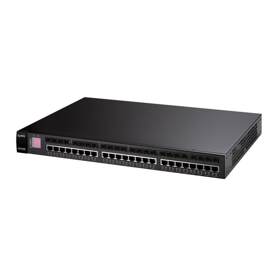
Page 35: Hardware Overview
For each interface you can connect either to the 1000Base-T port or the mini-GBIC port. The mini-GBIC ports have priority over the 1000Base-T ports. This means that if a mini-GBIC port and the corresponding 1000Base-T port are connected at the same time, the 1000Base-T port will be disabled. XGS-4728F User’s Guide... -
Page 36: 1000Base-T Ports
• Connection speed: 1 Gigabit per second (Gbps) To avoid possible eye injury, do not look into an operating fiber- optic module’s connectors. 3.1.3.1 Transceiver Installation Use the following steps to install a mini GBIC transceiver (SFP or XFP module). XGS-4728F User’s Guide... -
Page 37: Transceiver Removal
Figure 10 Installed Transceiver 3.1.3.2 Transceiver Removal Use the following steps to remove a mini GBIC transceiver (SFP module). Open the transceiver’s latch (latch styles vary). Figure 11 Opening the Transceiver’s Latch Example XGS-4728F User’s Guide... -
Page 38: Rear Panel
• An RS-232 management console port (E) • A connector for the power receptacle (F) • A power switch (G) (DC power input model only). Figure 13 Rear Panel - AC Model Figure 14 Rear Panel - DC Model XGS-4728F User’s Guide... -
Page 39: Power Connector
For EM-412 connection: Use 10GBase-CX4 cables to connect to these ports. See the EM-422 and EM-412 User’s Guides for more information. Two stacking Connect these ports to other XGS-4728F switches for stacking using ports stacking cables. Management Connect to a computer using an RJ-45 Ethernet cable for local Port configuration of the Switch. -
Page 40: External Backup Power Supply Connector
The system is turned on. The system is off. Green Blinking The system is rebooting and performing self-diagnostic tests. The system is on and functioning properly. The power is off or the system is not ready/ malfunctioning. XGS-4728F User’s Guide... - Page 41 The link to a 100 Mbps Ethernet network is up. The link to an Ethernet network is down. 1000Base-X Mini-GBIC Slots ( 1-24 Green The port has a successful connection. Blinking The port is receiving or transmitting data. This link is disconnected. XGS-4728F User’s Guide...
- Page 42 Chapter 3 Hardware Overview XGS-4728F User’s Guide...
-
Page 43: Basic Configuration
Basic Configuration The Web Configurator (45) Initial Setup Example (57) System Status and Port Statistics (73) Basic Setting (79) -
Page 45: The Web Configurator
• JavaScript (enabled by default). • Java permissions (enabled by default). 4.2 System Login Start your web browser. Type “http://” and the IP address of the Switch (for example, the default is 192.168.1.1) in the Location or Address field. Press [ENTER]. XGS-4728F User’s Guide... -
Page 46: The Status Screen
General Setup screen. Figure 16 Web Configurator: Login Click OK to view the first web configurator screen. 4.3 The Status Screen The Status screen is the first screen that displays when you access the web configurator. XGS-4728F User’s Guide... - Page 47 C - Click this link to go to the status page of the Switch. D - Click this link to log out of the web configurator. E - Click this link to display web help pages. The help pages provide descriptions for all of the configuration screens. XGS-4728F User’s Guide...
- Page 48 Chapter 4 The Web Configurator In the navigation panel, click a main link to reveal a list of submenu links. Table 4 Navigation Panel Sub-links Overview ADVANCED BASIC SETTING IP APPLICATION MANAGEMENT APPLICATION XGS-4728F User’s Guide...
- Page 49 Link Aggregation Setting - Link Aggregation Control VRRP Routing Table (Status) Protocol Configuration Port Authentication Configure Clone 802.1x MAC Authentication Port Security VLAN MAC Address Limit Classifier Policy Rule Queuing Method VLAN Stacking Port-based QinQ Selective QinQ XGS-4728F User’s Guide...
- Page 50 GARP and priority queues. IP Setup This link takes you to a screen where you can configure the IP address, subnet mask (necessary for Switch management) and DNS (domain name server) and set up to 64 IP routing domains. XGS-4728F User’s Guide...
- Page 51 RADIUS (Remote Authentication Dial-In User Service) or TACACS+ (Terminal Access Controller Access-Control System Plus). IP Source This link takes you to screens where you can configure filtering of Guard unauthorized DHCP and ARP packets in your network. XGS-4728F User’s Guide...
- Page 52 VLAN ID of a device attached to a port.You can also view what kind of device it is. ARP Table This link takes you to a screen where you can view the MAC address – IP address resolution table. XGS-4728F User’s Guide...
-
Page 53: Change Your Password
Click the Save link in the upper right hand corner of the web configurator to save your configuration to nonvolatile memory. Nonvolatile memory refers to the Switch’s storage that remains even if the Switch’s power is turned off. Note: Use the Save link when you are done with a configuration session. XGS-4728F User’s Guide... -
Page 54: Switch Lockout
9600bps with 8 data bit, no parity, one stop bit and flow control set to none. The password will also be reset to “1234” and the IP address to 192.168.1.1. To upload the configuration file, do the following: XGS-4728F User’s Guide... - Page 55 Press any key to enter debug mode within 3 seconds........Enter Debug Mode ras> atlc Starting XMODEM upload (CRC mode)..CCCCCCCCCCCCCCCC Total 393216 bytes received. Erasing..............ras> atgo The Switch is now reinitialized with a default configuration file including the default password of “1234”. XGS-4728F User’s Guide...
-
Page 56: Logging Out Of The Web Configurator
Figure 20 Web Configurator: Logout Screen 4.8 Help The web configurator’s online help has descriptions of individual screens and some supplementary information. Click the Help link from a web configurator screen to view an online help description of that screen. XGS-4728F User’s Guide... -
Page 57: Initial Setup Example
In the example network, since the RD network is already in the same IP interface as the Switch, you don’t need to create an IP interface for it. However, if you want to have the Sales network on a different routing domain, you need to create a XGS-4728F User’s Guide... - Page 58 Click Basic Setting and IP Setup in the navigation panel. Configure the related fields in the IP Setup screen. EXAMPLE For the Sales network, enter 192.168.2.1 as the IP address and 255.255.255.0 as the subnet mask. XGS-4728F User’s Guide...
-
Page 59: Configuring Dhcp Server Settings
Switch’s power is turned off. 5.1.3 Creating a VLAN VLANs confine broadcast frames to the VLAN group in which the port(s) belongs. You can do this with port-based VLAN or tagged static VLAN with fixed port members. XGS-4728F User’s Guide... - Page 60 Name field and enter 2 in the VLAN Group ID field for the VLAN2 network. EXAMPLE Note: The VLAN Group ID field in this screen and the VID field in the IP Setup screen refer to the same VLAN ID. XGS-4728F User’s Guide...
-
Page 61: Setting Port Vid
Setting link. Enter 2 in the PVID field for port 1 and click Apply to save your changes back to the run-time memory. Settings in the run-time EXAMPLE memory are lost when the Switch’s power is turned off. XGS-4728F User’s Guide... -
Page 62: Enabling Rip
In the Version field, select RIP-1 for the RIP packet format that is universally EXAMPLE supported. Click Apply to save your changes back to the run-time memory. Settings in the run-time memory are lost when the Switch’s power is turned off. XGS-4728F User’s Guide... -
Page 63: Tutorials
The settings in this tutorial are as the following. Table 8 Tutorial: Settings in this Tutorial PORT DHCP SNOOPING HOST VLAN PVID CONNECTED PORT TRUSTED DHCP Server (A) 1 and 100 DHCP Client (B) 1 and 100 DHCP Client (C) 1 and 100 XGS-4728F User’s Guide... - Page 64 100. Add ports 5, 6 and 7 in the VLAN by selecting Fixed in the Control field as shown. Deselect Tx Tagging because you don’t want outgoing traffic to contain this VLAN tag. Click Add. Figure 25 Tutorial: Create a VLAN and Add Ports to It XGS-4728F User’s Guide...
- Page 65 Go to Advanced Application > IP Source Guard > DHCP snooping > Configure, activate and specify VLAN 100 as the DHCP VLAN as shown. Click Apply. Figure 27 Tutorial: Specify DHCP VLAN Click the Port link at the top right corner. XGS-4728F User’s Guide...
- Page 66 VLAN ID or system name, you can also select the Option82 and Information fields in the entry. See Section 26.1.1.3 on page 233. Figure 29 Tutorial: Enable DHCP Snooping on this VLAN Click Save at the top right corner of the web configurator to save the configuration permanently. XGS-4728F User’s Guide...
-
Page 67: How To Use Dhcp Relay On The Switch
DHCP requests. 6.2.1 DHCP Relay Tutorial Introduction In this example, you have configured your DHCP server (192.168.2.3) and want to have it assign a specific IP address (say 172.16.1.18) to DHCP client A based on XGS-4728F User’s Guide... -
Page 68: Creating A Vlan
Access the web configurator through the Switch’s management port. Go to Basic Setting > Switch Setup and set the VLAN type to 802.1Q. Click Apply to save the settings to the run-time memory. Figure 32 Tutorial: Set VLAN Type to 802.1Q XGS-4728F User’s Guide... - Page 69 Clear the TX Tagging check box to set the Switch to remove VLAN tags before sending. Click Add to save the settings to the run-time memory. Settings in the run-time memory are lost when the Switch’s power is turned off. Figure 33 Tutorial: Create a Static VLAN XGS-4728F User’s Guide...
- Page 70 10 Click Apply to save your changes back to the run-time memory. Figure 35 Tutorial: Add Tag for Frames Received on Port 2 11 Click the Save link in the upper right corner of the web configurator to save your configuration permanently. XGS-4728F User’s Guide...
-
Page 71: Configuring Dhcp Relay
Check the client A’s IP address. If it did not receive the IP address 172.16.1.18, make sure: Client A is connected to the Switch’s port 2 in VLAN 102. You configured the correct VLAN ID, port number and system name for DHCP relay on both the DHCP server and the Switch. XGS-4728F User’s Guide... - Page 72 Chapter 6 Tutorials You clicked the Save link on the Switch to have your settings take effect. XGS-4728F User’s Guide...
-
Page 73: System Status And Port Statistics
The home screen of the web configurator displays a port statistical summary with links to each port showing statistical details. 7.2 Port Status Summary To view the port statistics, click Status in all web configurator screens to display the Status screen as shown next. Figure 37 Status XGS-4728F User’s Guide... - Page 74 This field shows the total amount of time in hours, minutes and seconds the port has been up. Clear Counter Type a port number, select Port and then click Clear Counter to erase the recorded statistical information for that port, or select Any to clear statistics for all ports. XGS-4728F User’s Guide...
-
Page 75: Status: Port Details
This field displays the speed (either 10M for 10Mbps, 100M for 100Mbpsl, 1000M for 1000 Mbps, and 10G for 10 Gbps) and the duplex (F for full duplex or H for half duplex). It also shows the cable type (Copper or Fiber). XGS-4728F User’s Guide... - Page 76 Excessive collision is defined as the number of maximum collisions before the retransmission count is reset. Late This is the number of times a late collision is detected, that is, after 512 bits of the packets have already been transmitted. XGS-4728F User’s Guide...
- Page 77 This field shows the number of packets (including bad packets) received 1518 that were between 1024 and 1518 octets in length. Giant This field shows the number of packets dropped because they were bigger than the maximum frame size. XGS-4728F User’s Guide...
- Page 78 Chapter 7 System Status and Port Statistics XGS-4728F User’s Guide...
-
Page 79: Basic Setting
Setup screen allows you to set up and configure global Switch features. The IP Setup screen allows you to configure a Switch IP address in each routing domain, subnet mask(s) and DNS (domain name server) for management purposes. XGS-4728F User’s Guide... -
Page 80: System Information
This shows the current temperature at this sensor. This field displays the maximum temperature measured at this sensor. This field displays the minimum temperature measured at this sensor. Threshold This field displays the upper temperature limit at this sensor. XGS-4728F User’s Guide... - Page 81 This field displays the minimum voltage measured at this point. Threshold This field displays the percentage tolerance of the voltage with which the Switch still works. Status Normal indicates that the voltage is within an acceptable operating range at this point; otherwise Error is displayed. XGS-4728F User’s Guide...
-
Page 82: General Setup
Type the geographic location of your Switch. You can use up to 32 printable ASCII characters; spaces are allowed. Contact Type the name of the person in charge of this Switch. You can use up to Person's Name 32 printable ASCII characters; spaces are allowed. XGS-4728F User’s Guide... - Page 83 European Union you would select Last, Sunday, March and the last field depends on your time zone. In Germany for instance, you would select 2:00 because Germany's time zone is one hour ahead of GMT or UTC (GMT+1). XGS-4728F User’s Guide...
-
Page 84: Introduction To Vlans
With VLAN, all broadcasts are confined to a specific broadcast domain. Note: VLAN is unidirectional; it only governs outgoing traffic. Chapter 9 on page 95 for information on port-based and 802.1Q tagged VLANs. XGS-4728F User’s Guide... -
Page 85: Switch Setup Screen
Join message using GARP. Declarations are withdrawn by issuing a Leave message. A Leave All message terminates all registrations. GARP timers set declaration timeout values. See Chapter 9 on page 95 for more background information. XGS-4728F User’s Guide... - Page 86 Switch loses these changes if it is turned off or loses power, so use the Save link on the top navigation panel to save your changes to the non- volatile memory when you are done configuring. Cancel Click Cancel to begin configuring this screen afresh. XGS-4728F User’s Guide...
-
Page 87: Ip Setup
To change the IP address of the Switch in a routing domain, simply add a new routing domain entry with a different IP address in the same subnet. Figure 42 Basic Setting > IP Setup XGS-4728F User’s Guide... - Page 88 Cancel Click Cancel to reset the fields to your previous configuration. Index This field displays the index number of an entry. IP Address This field displays IP address of the Switch in the IP domain. XGS-4728F User’s Guide...
-
Page 89: Port Setup
Note: Changes in this row are copied to all the ports as soon as you make them. Active Select this check box to enable a port. The factory default for all ports is enabled. A port must be enabled for data transmission to occur. XGS-4728F User’s Guide... - Page 90 Select Flow Control to enable it. 802.1p This priority value is added to incoming frames without a (802.1p) priority Priority queue tag. See Priority Queue Assignment in Table 13 on page 85 more information. XGS-4728F User’s Guide...
- Page 91 Switch loses these changes if it is turned off or loses power, so use the Save link on the top navigation panel to save your changes to the non- volatile memory when you are done configuring. Cancel Click Cancel to begin configuring this screen afresh. XGS-4728F User’s Guide...
- Page 92 Chapter 8 Basic Setting XGS-4728F User’s Guide...
-
Page 93: Advanced Setup
Advanced Setup VLAN (95) Loop Guard (255) Static MAC Forward Setup (115) VLAN Mapping (259) Static Multicast Forward Setup (119) Layer 2 Protocol Tunneling (263) Filtering (123) Spanning Tree Protocol (125) Bandwidth Control (145) Broadcast Storm Control (149) Mirroring (151) Link Aggregation (153) Port Authentication (163) Port Security (169) -
Page 95: Vlan
3 Bits 1 Bit 12 bits 9.1.1 Forwarding Tagged and Untagged Frames Each port on the Switch is capable of passing tagged or untagged frames. To forward a frame from an 802.1Q VLAN-aware switch to an 802.1Q VLAN-unaware XGS-4728F User’s Guide... -
Page 96: Automatic Vlan Registration
Please refer to the following table for common IEEE 802.1Q VLAN terminology. Table 16 IEEE 802.1Q VLAN Terminology VLAN TERM DESCRIPTION PARAMETER VLAN Type Permanent VLAN This is a static VLAN created manually. Dynamic VLAN This is a VLAN configured by a GVRP registration/ deregistration process. XGS-4728F User’s Guide... -
Page 97: Port Vlan Trunking
VLAN group tags. However, with VLAN Trunking enabled on a port(s) in each intermediary switch you only need to create VLAN groups in the end devices (A and B). C, D and E automatically XGS-4728F User’s Guide... -
Page 98: Select The Vlan Type
• sent to a group whether it has a VLAN tag or not. • blocked from a VLAN group regardless of its VLAN tag. You can also tag all outgoing frames (that were previously untagged) from a port with the specified VID. XGS-4728F User’s Guide... -
Page 99: Vlan Status
GVRP, static - added as a permanent entry or other - added in another way such as via Multicast VLAN Registration (MVR). Change Pages Click Previous or Next to show the previous/next screen if all status information cannot be seen in one screen. XGS-4728F User’s Guide... -
Page 100: Vlan Details
Multicast VLAN Registration (MVR). 9.5.3 Configure a Static VLAN Use this screen to configure and view 802.1Q VLAN parameters for the Switch. Section 9.1 on page 95 for more information on static VLAN. To configure a XGS-4728F User’s Guide... - Page 101 Use this row only if you want to make some settings the same for all ports. Use this row first to set the common settings and then make adjustments on a port-by-port basis. Note: Changes in this row are copied to all the ports as soon as you make them. XGS-4728F User’s Guide...
-
Page 102: Configure Vlan Port Settings
See Section 9.1 on page 95 for more information on static VLAN. Click the VLAN Port Setting link in the VLAN Status screen. Figure 49 Advanced Application > VLAN > VLAN Port Setting XGS-4728F User’s Guide... -
Page 103: Subnet Based Vlans
Subnet based VLANs allow you to group traffic into logical VLANs based on the source IP subnet you specify. When a frame is received on a port, the Switch checks if a tag is added already and the IP subnet it came from. The untagged XGS-4728F User’s Guide... -
Page 104: Configuring Subnet Based Vlan
Internet Untagged Frames 10.1.1.0/24 172.16.1.0/24 192.168.1.0/24 VID = 300 VID = 100 VID = 200 9.7 Configuring Subnet Based VLAN Click Subnet Based VLAN in the VLAN Port Setting screen to display the configuration screen as shown. XGS-4728F User’s Guide... - Page 105 1’s together. Take “255.255.255.0” for example. 255 converts to eight 1s in binary. There are three 255s, so add three eights together and you get the bit number (24). XGS-4728F User’s Guide...
-
Page 106: Protocol Based Vlans
3 for ARP traffic received on port 1, 2 and 3. You can also have a protocol based VLAN B with priority 2 for Apple Talk traffic received on port 6 and 7. All upstream ARP traffic from port 1, 2 and 3 will be grouped together, and all upstream Apple XGS-4728F User’s Guide... -
Page 107: Configuring Protocol Based Vlan
Figure 52 Protocol Based VLAN Application Example 9.9 Configuring Protocol Based VLAN Click Protocol Based VLAN in the VLAN Port Setting screen to display the configuration screen as shown. Figure 53 Advanced Application > VLAN > VLAN Port Setting > Protocol Based VLAN XGS-4728F User’s Guide... - Page 108 This field shows the priority which is assigned to frames belonging to this protocol based VLAN. Delete Click this to delete the protocol based VLANs which you marked for deletion. Cancel Click Cancel to begin configuring this screen afresh. XGS-4728F User’s Guide...
-
Page 109: Create An Ip-Based Vlan Example
To add more ports to this protocol based VLAN. Click the index number of the protocol based VLAN entry. Click 1 Change the value in the Port field to the next port you want to add. Click Add. XGS-4728F User’s Guide... -
Page 110: Port-Based Vlan Setup
Connected or Port Isolated from the drop-down list depending on your VLAN and VLAN security requirements. If VLAN members need to communicate directly with each other, then select All Connected. Select Port Isolated if you want to restrict users from communicating directly. Click Apply to save your settings. XGS-4728F User’s Guide... - Page 111 Chapter 9 VLAN The following screen shows users on a port-based, all-connected VLAN configuration. Figure 55 Advanced Application > VLAN > Port Based VLAN Setup (All Connected) XGS-4728F User’s Guide...
- Page 112 Chapter 9 VLAN The following screen shows users on a port-based, port-isolated VLAN configuration. Figure 56 Advanced Application > VLAN: Port Based VLAN Setup (Port Isolation) XGS-4728F User’s Guide...
- Page 113 Switch loses these changes if it is turned off or loses power, so use the Save link on the top navigation panel to save your changes to the non- volatile memory when you are done configuring. Cancel Click Cancel to begin configuring this screen afresh. XGS-4728F User’s Guide...
- Page 114 Chapter 9 VLAN XGS-4728F User’s Guide...
-
Page 115: Static Mac Forward Setup
Static MAC address forwarding together with port security allows only computers in the MAC address table on a port to access the Switch. See Chapter 19 on page for more information on port security. XGS-4728F User’s Guide... - Page 116 MAC address-forwarding rule. MAC Address This field displays the MAC address that will be forwarded and the VLAN identification number to which the MAC address belongs. This field displays the ID number of the VLAN group. XGS-4728F User’s Guide...
- Page 117 This field displays the port where the MAC address shown in the next field will be forwarded. Delete Click Delete to remove the selected entry from the summary table. Cancel Click Cancel to clear the Delete check boxes. XGS-4728F User’s Guide...
- Page 118 Chapter 10 Static MAC Forward Setup XGS-4728F User’s Guide...
-
Page 119: Static Multicast Forward Setup
24.3 on page 201). Figure 58 shows such unknown multicast frames flooded to all ports. With static multicast forwarding, you can forward these multicasts to port(s) within a VLAN group. Figure 59 shows frames being forwarded to devices XGS-4728F User’s Guide... -
Page 120: Configuring Static Multicast Forwarding
Figure 59 Static Multicast Forwarding to A Single Port Figure 60 Static Multicast Forwarding to Multiple Ports 11.2 Configuring Static Multicast Forwarding Use this screen to configure rules to forward specific multicast frames, such as streaming or control frames, to specific port(s). XGS-4728F User’s Guide... - Page 121 Cancel Click Cancel to reset the fields to their last saved values. Clear Click Clear to begin configuring this screen afresh. Index Click an index number to modify a static multicast MAC address rule for port(s). XGS-4728F User’s Guide...
- Page 122 This field displays the port(s) within a identified VLAN group to which frames containing the specified multicast MAC address will be forwarded. Delete Click Delete to remove the selected entry from the summary table. Cancel Click Cancel to clear the Delete check boxes. XGS-4728F User’s Guide...
-
Page 123: Filtering
Make sure to select this check box to activate your rule. You may temporarily deactivate a rule without deleting it by deselecting this check box. Name Type a descriptive name (up to 32 printable ASCII characters) for this rule. This is for identification only. XGS-4728F User’s Guide... - Page 124 This field displays the VLAN group identification number. Delete Check the rule(s) that you want to remove in the Delete column and then click the Delete button. Cancel Click Cancel to clear the selected checkbox(es) in the Delete column. XGS-4728F User’s Guide...
-
Page 125: Spanning Tree Protocol
Both RSTP and STP flush unwanted learned addresses from the filtering database. In RSTP, the port states are Discarding, Learning, and Forwarding. Note: In this user’s guide, “STP” refers to both STP and RSTP. 13.1.1 STP Terminology The root bridge is the base of the spanning tree. XGS-4728F User’s Guide... -
Page 126: How Stp Works
Hello BPDU after a predefined interval (Max Age), the bridge assumes that the link to the root bridge is down. This bridge then initiates negotiations with other bridges to reconfigure the network to re-establish a valid network topology. XGS-4728F User’s Guide... -
Page 127: Stp Port States
In the following example, there are two RSTP instances (MRSTP 1 and MRSTP2) on switch A. Figure 63 MRSTP Network Example To set up MRSTP, activate MRSTP on the Switch and specify which port(s) belong to which spanning tree. XGS-4728F User’s Guide... -
Page 128: Multiple Stp
If the switches are using STP or RSTP, the link for VLAN 2 will be blocked as STP and RSTP allow only one link in the network and block the redundant link. Figure 64 STP/RSTP Network Example VLAN 1 VLAN 2 XGS-4728F User’s Guide... -
Page 129: Mst Region
An MST Instance (MSTI) is a spanning tree instance. VLANs can be configured to run on a specific MSTI. Each created MSTI is identified by a unique number (known as an MST ID) known internally to a region. Thus an MSTI does not span across MST regions. XGS-4728F User’s Guide... - Page 130 MSTP-enabled network, there is only one CIST that runs between MST regions and single spanning tree devices. A network may contain multiple MST regions and other network segments running RSTP. Figure 67 MSTP and Legacy RSTP Network Example XGS-4728F User’s Guide...
-
Page 131: Spanning Tree Protocol Status Screen
13.3 Spanning Tree Configuration Use the Spanning Tree Configuration screen to activate one of the STP modes on the Switch. Click Configuration in the Advanced Application > Spanning Tree Protocol. Figure 69 Advanced Application > Spanning Tree Protocol > Configuration XGS-4728F User’s Guide... -
Page 132: Configure Rapid Spanning Tree Protocol
Use this screen to configure RSTP settings, see Section 13.1 on page 125 for more information on RSTP. Click RSTP in the Advanced Application > Spanning Tree Protocol screen. Figure 70 Advanced Application > Spanning Tree Protocol > RSTP XGS-4728F User’s Guide... - Page 133 Use this row only if you want to make some settings the same for all ports. Use this row first to set the common settings and then make adjustments on a port-by-port basis. Note: Changes in this row are copied to all the ports as soon as you make them. XGS-4728F User’s Guide...
-
Page 134: Rapid Spanning Tree Protocol Status
See Section 13.1 on page 125 more information on RSTP. Note: This screen is only available after you activate RSTP on the Switch. Figure 71 Advanced Application > Spanning Tree Protocol > Status: RSTP XGS-4728F User’s Guide... - Page 135 Switch must communicate with the root of the Spanning Tree. Topology This is the number of times the spanning tree has been reconfigured. Changed Times Time Since Last This is the time since the spanning tree was last reconfigured. Change XGS-4728F User’s Guide...
-
Page 136: Configure Multiple Rapid Spanning Tree Protocol
Select this check box to activate an STP tree. Clear this checkbox to disable an STP tree. Note: You must also activate Multiple Rapid Spanning Tree in the Advanced Application > Spanning Tree Protocol > Configuration screen to enable MRSTP on the Switch. XGS-4728F User’s Guide... - Page 137 Path cost is the cost of transmitting a frame on to a LAN through that port. It is recommended that you assign this value according to the speed of the bridge. The slower the media, the higher the cost - see Table 27 on page 126 for more information. XGS-4728F User’s Guide...
-
Page 138: Multiple Rapid Spanning Tree Protocol Status
Bridge is this Switch. This Switch may also be the root bridge. Bridge ID This is the unique identifier for this bridge, consisting of bridge priority plus MAC address. This ID is the same for Root and Our Bridge if the Switch is the root switch. XGS-4728F User’s Guide... - Page 139 Switch must communicate with the root of the Spanning Tree. Topology This is the number of times the spanning tree has been reconfigured. Changed Times Time Since Last This is the time since the spanning tree was last reconfigured. Change XGS-4728F User’s Guide...
-
Page 140: Configure Multiple Spanning Tree Protocol
13.8 Configure Multiple Spanning Tree Protocol To configure MSTP, click MSTP in the Advanced Application > Spanning Tree Protocol screen. See Section 13.1.5 on page 128 for more information on MSTP. Figure 74 Advanced Application > Spanning Tree Protocol > MSTP XGS-4728F User’s Guide... - Page 141 Click Cancel to begin configuring this screen afresh. Instance Use this section to configure MSTI (Multiple Spanning Tree Instance) settings. Instance Enter the number you want to use to identify this MST instance on the Switch. The Switch supports instance numbers 0-16. XGS-4728F User’s Guide...
- Page 142 This field displays the ID of an MST instance. VLAN This field displays the VID (or VID ranges) to which the MST instance is mapped. Active Port This field display the ports configured to participate in the MST instance. XGS-4728F User’s Guide...
-
Page 143: Multiple Spanning Tree Protocol Status
Table 35 Advanced Application > Spanning Tree Protocol > Status: MSTP LABEL DESCRIPTION Configuration Click Configuration to specify which STP mode you want to activate. Click MSTP to edit MSTP settings on the Switch. This section describes the Common Spanning Tree settings. XGS-4728F User’s Guide... - Page 144 This is the path cost from the root port in this MST instance to the regional root switch. Port ID This is the priority and number of the port on the Switch through which this Switch must communicate with the root of the MST instance. XGS-4728F User’s Guide...
-
Page 145: Bandwidth Control
CIR will be marked for drop. Note: The CIR should be less than the PIR. Note: The sum of CIRs cannot be greater than or equal to the uplink bandwidth. XGS-4728F User’s Guide... -
Page 146: Bandwidth Control Setup
The sum of commit rates cannot be greater than or equal to the uplink bandwidth. Active Select this check box to activate peak rate limits on this port. Peak Specify the maximum bandwidth allowed in kilobits per second (Kbps) for Rate the incoming traffic flow on a port. XGS-4728F User’s Guide... - Page 147 Switch loses these changes if it is turned off or loses power, so use the Save link on the top navigation panel to save your changes to the non- volatile memory when you are done configuring. Cancel Click Cancel to begin configuring this screen afresh. XGS-4728F User’s Guide...
- Page 148 Chapter 14 Bandwidth Control XGS-4728F User’s Guide...
-
Page 149: Broadcast Storm Control
DLF packets in your network. You can specify limits for each packet type on each port. Click Advanced Application > Broadcast Storm Control in the navigation panel to display the screen as shown next. Figure 77 Advanced Application > Broadcast Storm Control XGS-4728F User’s Guide... - Page 150 Switch loses these changes if it is turned off or loses power, so use the Save link on the top navigation panel to save your changes to the non- volatile memory when you are done configuring. Cancel Click Cancel to begin configuring this screen afresh. XGS-4728F User’s Guide...
-
Page 151: Mirroring
Click Advanced Application > Mirroring in the navigation panel to display the Mirroring screen. Use this screen to select a monitor port and specify the traffic flow to be copied to the monitor port. Figure 78 Advanced Application > Mirroring XGS-4728F User’s Guide... - Page 152 Switch loses these changes if it is turned off or loses power, so use the Save link on the top navigation panel to save your changes to the non-volatile memory when you are done configuring. Cancel Click Cancel to begin configuring this screen afresh. XGS-4728F User’s Guide...
-
Page 153: Link Aggregation
The Switch adheres to the IEEE 802.3ad standard for static and dynamic (LACP) port trunking. The Switch supports the link aggregation IEEE802.3ad standard. This standard describes the Link Aggregation Control Protocol (LACP), which is a protocol that dynamically creates and manages trunk groups. XGS-4728F User’s Guide... -
Page 154: Link Aggregation Id
Table 40 Link Aggregation ID: Peer Switch SYSTEM PORT PORT MAC ADDRESS PRIORITY PRIORITY NUMBER 0000 00-00-00-00-00- 0000 0000 Port Priority and Port Number are 0 as it is the aggregator ID for the trunk group, not the individual port. XGS-4728F User’s Guide... -
Page 155: Link Aggregation Status
Refer to Section 17.2.1 on page 154 for more information on this field. The ID displays only when there is a port belonging to this trunk group and LACP is also enabled for this group. XGS-4728F User’s Guide... - Page 156 This field displays how these ports were added to the trunk group. It displays: • Static - if the ports are configured as static members of a trunk group. • LACP - if the ports are configured to join a trunk group via LACP. XGS-4728F User’s Guide...
-
Page 157: Link Aggregation Setting
This is the only screen you need to configure to enable static link Aggregation aggregation. Setting Group ID The field identifies the link aggregation group, that is, one logical link containing multiple ports. Active Select this option to activate a trunk group. XGS-4728F User’s Guide... - Page 158 Switch loses these changes if it is turned off or loses power, so use the Save link on the top navigation panel to save your changes to the non- volatile memory when you are done configuring. Cancel Click Cancel to begin configuring this screen afresh. XGS-4728F User’s Guide...
-
Page 159: Link Aggregation Control Protocol
Table 43 Advanced Application > Link Aggregation > Link Aggregation Setting > LACP LABEL DESCRIPTION Link Note: Do not configure this screen unless you want to enable Aggregation dynamic link aggregation. Control Protocol Active Select this checkbox to enable Link Aggregation Control Protocol (LACP). XGS-4728F User’s Guide... -
Page 160: Static Trunking Example
Save link on the top navigation panel to save your changes to the non- volatile memory when you are done configuring. Cancel Click Cancel to begin configuring this screen afresh. 17.6 Static Trunking Example This example shows you how to create a static port trunk group for ports 2-5. XGS-4728F User’s Guide... - Page 161 Click Apply when you are done. Figure 83 Trunking Example - Configuration Screen EXAMPLE Your trunk group 1 (T1) configuration is now complete. XGS-4728F User’s Guide...
- Page 162 Chapter 17 Link Aggregation XGS-4728F User’s Guide...
-
Page 163: Port Authentication
When the client provides the login credentials, the Switch sends an authentication At the time of writing, IEEE 802.1x is not supported by all operating systems. See your operating system documentation. If your operating system does not support 802.1x, then you may need to install 802.1x client software. XGS-4728F User’s Guide... -
Page 164: Mac Authentication
MAC authentication works in a very similar way to IEEE 802.1x authentication. The main difference is that the Switch does not prompt the client for login credentials. The login credentials are based on the source MAC address of the XGS-4728F User’s Guide... -
Page 165: Port Authentication Configuration
AAA > Radius Server Setup screen. To activate a port authentication method, click Advanced Application > Port Authentication in the navigation panel. Select a port authentication method in the screen that appears. Figure 86 Advanced Application > Port Authentication XGS-4728F User’s Guide... -
Page 166: Activate Ieee 802.1X Security
Reauthenticati Specify the length of time required to pass before a client has to re-enter on Timer his or her username and password to stay connected to the port. XGS-4728F User’s Guide... -
Page 167: Activate Mac Authentication
Type the prefix that is appended to all MAC addresses sent to the RADIUS server for authentication. You can enter up to 32 printable ASCII characters. If you leave this field blank, then only the MAC address of the client is forwarded to the RADIUS server. XGS-4728F User’s Guide... - Page 168 Switch loses these changes if it is turned off or loses power, so use the Save link on the top navigation panel to save your changes to the non- volatile memory when you are done configuring. Cancel Click Cancel to begin configuring this screen afresh. XGS-4728F User’s Guide...
-
Page 169: Port Security
MAC address(es) for a port. It is not recommended you disable port security together with MAC address learning as this will result in many broadcasts. By default, MAC address learning is still enabled even though the port security is not activated. XGS-4728F User’s Guide... -
Page 170: Port Security Setup
Use this row only if you want to make some of the settings the same for all ports. Use this row first to set the common settings and then make adjustments on a port-by-port basis. Note: Changes in this row are copied to all the ports as soon as you make them. XGS-4728F User’s Guide... -
Page 171: Vlan Mac Address Limit
Use this screen to set the MAC address learning limit on per-port and per-VLAN basis. Click VLAN MAC Address Limit in the Advanced Application > Port Security screen to display the screen as shown. Figure 90 Advanced Application > Port Security > VLAN MAC Address Limit XGS-4728F User’s Guide... - Page 172 This is the maximum number of MAC addresses which a port can learn in a VLAN. Delete Check the rule(s) that you want to remove in the Delete column and then click the Delete button. Cancel Click Cancel to clear the selected checkbox(es) in the Delete column. XGS-4728F User’s Guide...
-
Page 173: Classifier
Use the Classifier screen to define the classifiers. After you define the classifier, you can specify actions (or policy) to act upon the traffic that matches the rules. To configure policy rules, refer to Chapter 21 on page 179. XGS-4728F User’s Guide... - Page 174 Ethernet II tagged and Ethernet II untagged. A value of 802.3 indicates that the packets are formatted according to the IEEE 802.3 standards. A value of Ethernet II indicates that the packets are formatted according to RFC 894, Ethernet II encapsulation. XGS-4728F User’s Guide...
- Page 175 TCP/UDP protocol port number. Destination Enter a destination IP address in dotted decimal notation. Address/ Specify the address prefix by entering the number of ones in the subnet mask. Address Prefix XGS-4728F User’s Guide...
-
Page 176: Viewing And Editing Classifier Configuration
This field displays Yes when the rule is activated and No when it is deactivated. Name This field displays the descriptive name for this rule. This is for identification purposes only. Rule This field displays a summary of the classifier rule’s settings. XGS-4728F User’s Guide... - Page 177 0805 XNS Compat 0807 Banyan Systems 0BAD BBN Simnet 5208 IBM SNA 80D5 AppleTalk AARP 80F3 Some of the most common IP ports are: Table 51 Common IP Ports PORT PORT NAME NUMBER Telnet SMTP HTTP POP3 XGS-4728F User’s Guide...
-
Page 178: Classifier Example
Figure 93 Classifier: Example EXAMPLE After you have configured a classifier, you can configure a policy to define action(s) on the classified traffic flow. See Chapter 21 on page 179 for information on configuring a policy rule. XGS-4728F User’s Guide... -
Page 179: Policy Rule
DS field. DSCP is backward compatible with the three precedence bits in the ToS octet so that non-DiffServ compliant, ToS-enabled network device will not conflict with the DSCP mapping. DSCP (6 bits) Unused (2 bits) XGS-4728F User’s Guide... -
Page 180: Configuring Policy Rules
DSCP values and the configured policies. 21.2 Configuring Policy Rules You must first configure a classifier in the Classifier screen. Refer to Section 20.2 on page 173 for more information. XGS-4728F User’s Guide... - Page 181 Chapter 21 Policy Rule Click Advanced Applications > Policy Rule in the navigation panel to display the screen as shown. Figure 94 Advanced Application > Policy Rule XGS-4728F User’s Guide...
- Page 182 Select Send the packet to priority queue to put the packets in the designated queue. Select Replace the 802.1 priority field with the IP TOS value to replace the packet’s 802.1 priority field with the value you set in the TOS field. XGS-4728F User’s Guide...
-
Page 183: Viewing And Editing Policy Configuration
To view a summary of the classifier configuration, scroll down to the summary table at the bottom of the Policy screen. To change the settings of a rule, click a number in the Index field. Figure 95 Advanced Application > Policy Rule: Summary Table XGS-4728F User’s Guide... - Page 184 This field displays the name you have assigned to this policy. Classifier( This field displays the name(s) of the classifier to which this policy applies. Delete Click Delete to remove the selected entry from the summary table. Cancel Click Cancel to clear the Delete check boxes. XGS-4728F User’s Guide...
-
Page 185: Policy Example
The figure below shows an example Policy screen where you configure a policy to limit bandwidth and discard out-of-profile traffic on a traffic flow classified using the Example classifier (refer to Section 20.4 on page 178). Figure 96 Policy Example EXAMPLE XGS-4728F User’s Guide... - Page 186 Chapter 21 Policy Rule XGS-4728F User’s Guide...
-
Page 187: Queuing Method
By default, the weight for Q0 is 1, for Q1 is 2, for Q2 is 3, and so on. The weights range from 1 to 15 and the actual guaranteed bandwidth is calculated as follows: XGS-4728F User’s Guide... -
Page 188: Weighted Round Robin Scheduling (Wrr)
Queues with larger weights get more service than queues with smaller weights. This queuing mechanism is highly efficient in that it divides any available bandwidth across the different traffic queues and returns to queues that have not yet emptied. XGS-4728F User’s Guide... -
Page 189: Configuring Queuing
Use this row only if you want to make some settings the same for all ports. Use this row first to set the common settings and then make adjustments on a port-by-port basis. Note: Changes in this row are copied to all the ports as soon as you make them. XGS-4728F User’s Guide... - Page 190 Switch loses these changes if it is turned off or loses power, so use the Save link on the top navigation panel to save your changes to the non-volatile memory when you are done configuring. Cancel Click Cancel to begin configuring this screen afresh. XGS-4728F User’s Guide...
-
Page 191: Vlan Stacking
(SPN) customers with VPN tunnels between their head offices and branch offices respectively. Both have an identical VLAN tag for their VLAN group. The service provider can separate these two VLANs within its network by adding tag 37 to XGS-4728F User’s Guide... -
Page 192: Vlan Stacking Port Roles
VLAN (using the outer VLAN tag defined by the Service Provider’s (SP) VLAN ID (VID)). Note: Static VLAN Tx Tagging MUST be enabled on a port where you choose Tunnel Port. XGS-4728F User’s Guide... -
Page 193: Vlan Tag Format
VID is the VLAN ID. SP VID is the VID for the second (service provider’s) VLAN tag. 23.3.1 Frame Format The frame format for an untagged Ethernet frame, a single-tagged 802.1Q frame (customer) and a “double-tagged” 802.1Q frame (service provider) is shown next. XGS-4728F User’s Guide... -
Page 194: Configuring Vlan Stacking
(SP)TPI (Service Provider) Tag Protocol Data Frame data IDentifier VLAN ID Frame Check Sequence 23.4 Configuring VLAN Stacking Click Advanced Applications > VLAN Stacking to display the screen as shown. Figure 99 Advanced Application > VLAN Stacking XGS-4728F User’s Guide... -
Page 195: Port-Based Q-In-Q
23.4.1 Port-based Q-in-Q Port-based Q-in-Q lets the Switch treat all frames received on the same port as the same VLAN flows and add the same outer VLAN tag to them, even they have different customer VLAN IDs. XGS-4728F User’s Guide... -
Page 196: Selective Q-In-Q
Note: Selective Q-in-Q rules are only applied to single-tagged frames received on the access ports. If the incoming frames are untagged or single-tagged but received on a tunnel port or cannot match any selective Q-in-Q rules, the Switch applies the port-based Q-in-Q rules to them. XGS-4728F User’s Guide... - Page 197 This is the port number to which this rule is applied. This is the customer VLAN ID in the incoming packets. SPVID This is the service provider’s VLAN ID that adds to the packets from the subscribers. XGS-4728F User’s Guide...
- Page 198 This is the service provider’s priority level in the packets. Delete Check the rule(s) that you want to remove in the Delete column and then click the Delete button. Cancel Click Cancel to clear the Delete check boxes. XGS-4728F User’s Guide...
-
Page 199: Multicast
(such as content information distribution) based on service plans and types of subscription. You can set the Switch to filter the multicast group join reports on a per-port basis by configuring an IGMP filtering profile and associating the profile to a port. XGS-4728F User’s Guide... -
Page 200: Igmp Snooping
This is the index number of the entry. This field displays the multicast VLAN ID. Port This field displays the port number that belongs to the multicast group. Multicast Group This field displays IP multicast group addresses. XGS-4728F User’s Guide... -
Page 201: Multicast Setting
Switch removes an IGMP group membership entry if it does not receive report messages from the port. 802.1p Priority Select a priority level (0-7) to which the Switch changes the priority in outgoing IGMP control packets. Otherwise, select No-Change to not replace the priority. XGS-4728F User’s Guide... - Page 202 This defines how many seconds the Switch waits for an IGMP report before removing an IGMP snooping membership entry when an IGMP leave message is received on this port from a host. XGS-4728F User’s Guide...
-
Page 203: Igmp Snooping Vlan
Cancel Click Cancel to begin configuring this screen afresh. 24.4 IGMP Snooping VLAN Click Advanced Applications > Multicast in the navigation panel. Click the Multicast Setting link and then the IGMP Snooping VLAN link to display the XGS-4728F User’s Guide... - Page 204 Click Cancel to begin configuring this screen afresh. VLAN Use this section of the screen to add VLANs upon which the Switch is to perform IGMP snooping. Name Enter the descriptive name of the VLAN for identification purposes. XGS-4728F User’s Guide...
-
Page 205: Igmp Filtering Profile
(in the Multicast Setting screen). Clients connected to those ports are then able to join the multicast groups specified in the profile. Each port can be assigned a single profile. A profile can be assigned to multiple ports. XGS-4728F User’s Guide... - Page 206 Click Clear to clear the fields to the factory defaults. Profile Name This field displays the descriptive name of the profile. Start Address This field displays the start of the multicast address range. End Address This field displays the end of the multicast address range. XGS-4728F User’s Guide...
-
Page 207: Mvr Overview
In MVR, a source port is a port on the Switch that can send and receive multicast traffic in a multicast VLAN while a receiver port can only receive multicast traffic. Once configured, the Switch maintains a forwarding table that matches the multicast stream to the associated multicast group. XGS-4728F User’s Guide... -
Page 208: Mvr Modes
Switch). If there is another subscriber device connected to this port in the same subscriber VLAN, the receiving port will still be on the list of forwarding destination for the multicast traffic. Otherwise, the Switch removes the receiver port from the forwarding table. Figure 107 MVR Multicast Television Example XGS-4728F User’s Guide... -
Page 209: General Mvr Configuration
Select this check box to enable MVR to allow one single multicast VLAN to be shared among different subscriber VLANs on the network. Name Enter a descriptive name (up to 32 printable ASCII characters) for identification purposes. XGS-4728F User’s Guide... - Page 210 This field displays the priority level. Delete To delete a multicast VLAN(s), select the rule(s) that you want to remove in the Delete column, then click the Delete button. Cancel Click Cancel to clear the Delete check boxes. XGS-4728F User’s Guide...
-
Page 211: Mvr Group Configuration
Enter the same IP address as the Start Address field if you want to configure only one IP address for a multicast group. Refer to Section 24.1.1 on page 199 for more information on IP multicast addresses. XGS-4728F User’s Guide... -
Page 212: Mvr Configuration Example
VID 200 to receive multicast traffic (the News and Movie channels) from the remote streaming media server, S. Computers A, B and C in VLAN 1 are able to receive the traffic. Figure 110 MVR Configuration Example XGS-4728F User’s Guide... - Page 213 Figure 111 MVR Configuration Example EXAMPLE To set the Switch to forward the multicast group traffic to the subscribers, configure multicast group settings in the Group Configuration screen. The XGS-4728F User’s Guide...
- Page 214 Chapter 24 Multicast following figure shows an example where two multicast groups (News and Movie) are configured for the multicast VLAN 200. Figure 112 MVR Group Configuration Example EXAMPLE Figure 113 MVR Group Configuration Example EXAMPLE XGS-4728F User’s Guide...
-
Page 215: Aaa
The external servers that perform authentication, authorization and accounting functions are known as AAA servers. The Switch supports RADIUS (Remote Authentication Dial-In User Service, see Section 25.1.2 on page 216) and TACACS+ (Terminal Access Controller Access-Control System Plus, see Section XGS-4728F User’s Guide... -
Page 216: Local User Accounts
The AAA screens allow you to enable authentication, authorization, accounting or all of them on the Switch. First, configure your authentication and accounting server settings (RADIUS, TACACS+ or both) and then set up the authentication priority, activate authorization and configure accounting settings. XGS-4728F User’s Guide... -
Page 217: Radius Server Setup
RADIUS attributes utilized by the authentication and accounting features on the Switch. Click on the RADIUS Server Setup link in the AAA screen to view the screen as shown. Figure 116 Advanced Application > AAA > RADIUS Server Setup XGS-4728F User’s Guide... - Page 218 Enter the IP address of an external RADIUS accounting server in dotted decimal notation. UDP Port The default port of a RADIUS accounting server for accounting is 1813. You need not change this value unless your network administrator instructs you to do so. XGS-4728F User’s Guide...
-
Page 219: Tacacs+ Server Setup
216 for more information on TACACS+ servers. Click on the TACACS+ Server Setup link in the Authentication and Accounting screen to view the screen as shown. Figure 117 Advanced Application > AAA > TACACS+ Server Setup XGS-4728F User’s Guide... - Page 220 Enter the IP address of an external TACACS+ accounting server in dotted decimal notation. TCP Port The default port of a TACACS+ accounting server is 49. You need not change this value unless your network administrator instructs you to do XGS-4728F User’s Guide...
-
Page 221: Aaa Setup
Use this screen to configure authentication, authorization and accounting settings on the Switch. Click on the AAA Setup link in the AAA screen to view the screen as shown. Figure 118 Advanced Application > AAA > AAA Setup XGS-4728F User’s Guide... - Page 222 Select radius to have the Switch check the administrator accounts configured via the RADIUS Server. Select tacacs+ to have the Switch check the administrator accounts configured via the TACACS+ Server. Authorization Use this section to configure authorization settings on the Switch. XGS-4728F User’s Guide...
- Page 223 This field is only configurable for Commands type of event. Select the threshold command privilege level for which the Switch should send accounting information. The Switch will send accounting information when commands at the level you specify and higher are executed on the Switch. XGS-4728F User’s Guide...
-
Page 224: Vendor Specific Attribute
The following table describes the VSAs supported on the Switch. Note that these atrributes only work when you enable authorization (see Section 25.2.3 on page 221). Table 71 Supported VSAs FUNCTION ATTRIBUTE Ingress Bandwidth Vendor-Id = 890 Assignment Vendor-Type = 1 Vendor-data = ingress rate (Kbps in decimal format) XGS-4728F User’s Guide... -
Page 225: Tunnel Protocol Attribute
Tunnel-Type = VLAN(13) Tunnel-Medium-Type = 802(6) Tunnel-Private-Group-ID = VLAN ID Note: You must also create a VLAN with the specified VID on the Switch. Note: The bolded values in this table are fixed values as defined in RFC 3580. XGS-4728F User’s Guide... -
Page 226: Supported Radius Attributes
- the format of the User-Name attribute is $enab#$, where # is the privilege level (1-14) User-Password NAS-Identifier NAS-IP-Address 25.3.1.2 Attributes Used to Login Users User-Name User-Password NAS-Identifier NAS-IP-Address 25.3.1.3 Attributes Used by the IEEE 802.1x Authentication User-Name NAS-Identifier NAS-IP-Address NAS-Port NAS-Port-Type XGS-4728F User’s Guide... -
Page 227: Attributes Used For Accounting
(the difference between Console and Telnet/SSH Exec events is that the Telnet/SSH events utilize the Calling-Station-Id attribute): Table 73 RADIUS Attributes - Exec Events via Console ATTRIBUTE START INTERIM-UPDATE STOP User-Name NAS-Identifier NAS-IP-Address Service-Type Acct-Status-Type Acct-Delay-Time Acct-Session-Id Acct-Authentic Acct-Session-Time Acct-Terminate-Cause XGS-4728F User’s Guide... - Page 228 The attributes are listed in the following table along with the time of the session they are sent: Table 75 RADIUS Attributes - Exec Events via Console ATTRIBUTE START INTERIM-UPDATE STOP User-Name NAS-IP-Address NAS-Port Class Called-Station-Id Calling-Station-Id NAS-Identifier NAS-Port-Type Acct-Status-Type Acct-Delay-Time Acct-Session-Id Acct-Authentic Acct-Input-Octets Acct-Output-Octets Acct-Session-Time Acct-Input-Packets Acct-Output-Packets Acct-Terminate-Cause XGS-4728F User’s Guide...
- Page 229 Chapter 25 AAA Table 75 RADIUS Attributes - Exec Events via Console ATTRIBUTE START INTERIM-UPDATE STOP Acct-Input-Gigawords Acct-Output- Gigawords XGS-4728F User’s Guide...
- Page 230 Chapter 25 AAA XGS-4728F User’s Guide...
-
Page 231: Ip Source Guard
• ARP inspection. Use this to filter unauthorized ARP packets on the network. If you want to use dynamic bindings to filter unauthorized ARP packets (typical implementation), you have to enable DHCP snooping before you enable ARP inspection. XGS-4728F User’s Guide... -
Page 232: Dhcp Snooping Overview
The DHCP snooping database maintains the dynamic bindings for DHCP snooping and ARP inspection in a file on an external TFTP server. If you set up the DHCP snooping database, the Switch can reload the dynamic bindings from the DHCP snooping database after the Switch restarts. XGS-4728F User’s Guide... -
Page 233: Configuring Dhcp Snooping
(Chapter 36 on page 303). 26.1.1.4 Configuring DHCP Snooping Follow these steps to configure DHCP snooping on the Switch. Enable DHCP snooping on the Switch. Enable DHCP snooping on each VLAN, and configure DHCP relay option 82. XGS-4728F User’s Guide... -
Page 234: Arp Inspection Overview
These MAC address filters are different than regular MAC address filters (Chapter 12 on page 123). • They are stored only in volatile memory. • They do not use the same space in memory that regular MAC address filters use. XGS-4728F User’s Guide... -
Page 235: Ip Source Guard
Use this screen to look at the current bindings for DHCP snooping and ARP inspection. Bindings are used by DHCP snooping and ARP inspection to distinguish between authorized and unauthorized packets in the network. The Switch learns XGS-4728F User’s Guide... -
Page 236: Ip Source Guard Static Binding
Static bindings are uniquely identified by the MAC address and VLAN ID. Each MAC address and VLAN ID can only be in one static binding. If you try to create a static binding with the same MAC address and VLAN ID as an existing static binding, the XGS-4728F User’s Guide... - Page 237 This binding was learned from information provided manually by an administrator. VLAN This field displays the source VLAN ID in the binding. Port This field displays the port number in the binding. If this field is blank, the binding applies to all ports. XGS-4728F User’s Guide...
-
Page 238: Dhcp Snooping
Click this to clear the Delete check boxes above. 26.4 DHCP Snooping Use this screen to look at various statistics about the DHCP snooping database. To open this screen, click Advanced Application > IP Source Guard > DHCP Snooping. Figure 123 DHCP Snooping XGS-4728F User’s Guide... - Page 239 DHCP snooping database for any reason. Startup failures This field displays the number of times the Switch could not create or read the DHCP snooping database when the Switch started up or a new URL is configured for the DHCP snooping database. XGS-4728F User’s Guide...
- Page 240 Switch already had a binding with the same MAC address and VLAN ID. Invalid interfaces This field displays the number of bindings the Switch has ignored because the port number was a trusted interface or does not exist anymore. XGS-4728F User’s Guide...
-
Page 241: Dhcp Snooping Configure
TFTP server so that they are still available after a restart. To open this screen, click Advanced Application > IP Source Guard > DHCP Snooping > Configure. Figure 124 DHCP Snooping Configure XGS-4728F User’s Guide... - Page 242 If there is a conflict, the Switch keeps the dynamic binding in volatile memory and updates the Binding collisions counter in the DHCP Snooping screen (Section 26.4 on page 238). XGS-4728F User’s Guide...
-
Page 243: Dhcp Snooping Port Configure
You can also specify the maximum number for DHCP packets that each port (trusted or untrusted) can receive each second. To open this screen, click Advanced Application > IP Source Guard > DHCP Snooping > Configure > Port. Figure 125 DHCP Snooping Port Configure XGS-4728F User’s Guide... -
Page 244: Dhcp Snooping Vlan Configure
Use this screen to enable DHCP snooping on each VLAN and to specify whether or not the Switch adds DHCP relay agent option 82 information (Chapter 36 on page 303) to DHCP requests that the Switch relays to a DHCP server for each VLAN. To XGS-4728F User’s Guide... - Page 245 DHCP VLAN, if specified, or VLAN. You can configure the system name in the General Setup screen. See Chapter 8 on page 79. You can specify the DHCP VLAN in the DHCP Snooping Configure screen. See Section 26.5 on page 241. XGS-4728F User’s Guide...
-
Page 246: Arp Inspection Status
Port This field displays the source port of the discarded ARP packet. Expiry (sec) This field displays how long (in seconds) the MAC address filter remains in the Switch. You can also delete the record manually (Delete). XGS-4728F User’s Guide... -
Page 247: Arp Inspection Vlan Status
Select this to look at all the VLANs in a specific range in the section below. Then, enter the lowest VLAN ID (Start VID) and the highest VLAN ID (End VID) you want to look at. Apply Click this to display the specified range of VLANs in the section below. XGS-4728F User’s Guide... -
Page 248: Arp Inspection Log Status
This field displays a sequential number for each log message. Port This field displays the source port of the ARP packet. This field displays the source VLAN ID of the ARP packet. Sender Mac This field displays the source MAC address of the ARP packet. XGS-4728F User’s Guide... -
Page 249: Arp Inspection Configure
This field displays when the log message was generated. 26.7 ARP Inspection Configure Use this screen to enable ARP inspection on the Switch. You can also configure the length of time the Switch stores records of discarded ARP packets and global XGS-4728F User’s Guide... - Page 250 Click Clearing log status table in the ARP Inspection Log Status screen to clear the log and reset this counter. See Section 26.6.2 on page 248. XGS-4728F User’s Guide...
-
Page 251: Arp Inspection Port Configure
Click this to reset the values in this screen to their last-saved values. 26.7.1 ARP Inspection Port Configure Use this screen to specify whether ports are trusted or untrusted ports for ARP inspection. You can also specify the maximum rate at which the Switch receives XGS-4728F User’s Guide... - Page 252 Rate and Burst Interval settings have no effect on trusted ports. Rate (pps) Specify the maximum rate (1-2048 packets per second) at which the Switch receives ARP packets from each port. The Switch discards any additional ARP packets. Enter 0 to disable this limit. XGS-4728F User’s Guide...
-
Page 253: Arp Inspection Vlan Configure
Use this section to specify the VLANs you want to manage in the section below. Start VID Enter the lowest VLAN ID you want to manage in the section below. End VID Enter the highest VLAN ID you want to manage in the section below. XGS-4728F User’s Guide... - Page 254 Save link on the top navigation panel to save your changes to the non-volatile memory when you are done configuring. Cancel Click this to reset the values in this screen to their last-saved values. XGS-4728F User’s Guide...
-
Page 255: Loop Guard
If a switch (not in loop state) connects to a switch in loop state, then it will be affected by the switch in loop state in the following way: • It will receive broadcast messages sent out from the switch in loop state. XGS-4728F User’s Guide... - Page 256 The following figure illustrates three switches forming a loop. A sample path of the loop guard probe packet is also shown. In this example, the probe packet is sent from port N and returns on another port. As long as loop guard is enabled on XGS-4728F User’s Guide...
-
Page 257: Loop Guard Setup
Click Advanced Application > Loop Guard in the navigation panel to display the screen as shown. Note: The loop guard feature can not be enabled on the ports that have Spanning Tree Protocol (RSTP, MRSTP or MSTP) enabled. Figure 137 Advanced Application > Loop Guard XGS-4728F User’s Guide... - Page 258 Switch loses these changes if it is turned off or loses power, so use the Save link on the top navigation panel to save your changes to the non- volatile memory when you are done configuring. Cancel Click Cancel to begin configuring this screen afresh. XGS-4728F User’s Guide...
-
Page 259: Vlan Mapping
VLAN ID from 12 into 123 before forwarding the packets. Any packets carrying a VLAN tag other than 12 (such as 10) and received on port 3 will be dropped. Figure 138 VLAN mapping example VLAN 123 Service Provider VLAN 10 Network Port 3 VLAN 12 VLAN 10 XGS-4728F User’s Guide... -
Page 260: Enabling Vlan Mapping
Switch loses these changes if it is turned off or loses power, so use the Save link on the top navigation panel to save your changes to the non- volatile memory when you are done configuring. Cancel Click Cancel to begin configuring this screen afresh. XGS-4728F User’s Guide... -
Page 261: Configuring Vlan Mapping
Click Cancel to reset the fields to your previous configuration. Index This is the number of the VLAN mapping entry in the table. Active This shows whether this entry is activated or not. Name This is the descriptive name for this rule. XGS-4728F User’s Guide... - Page 262 This is the priority level that replaces the customer priority level in the tagged packets. Delete Check the rule(s) that you want to remove in the Delete column and then click the Delete button. Cancel Click Cancel to clear the Delete check boxes. XGS-4728F User’s Guide...
-
Page 263: Layer 2 Protocol Tunneling
B, C and D. Topology change information can be propagated throughout the service provider’s network. To emulate a point-to-point topology between two customer switches at different sites, such as A and B, you can enable protocol tunneling on edge switches 1 and XGS-4728F User’s Guide... -
Page 264: Layer 2 Protocol Tunneling Mode
• The Tunnel port is an egress port at the edge of the service provider's network and connected to another service provider’s switch. Incoming encapsulated layer 2 protocol packets received on a tunnel port are decapsulated and sent to an access port. XGS-4728F User’s Guide... -
Page 265: Configuring Layer 2 Protocol Tunneling
Note: All the edge switches in the service provider’s network should be set to use the same MAC address for encapsulation. Port This field displays the port number. XGS-4728F User’s Guide... - Page 266 Switch loses these changes if it is turned off or loses power, so use the Save link on the top navigation panel to save your changes to the non- volatile memory when you are done configuring. Cancel Click Cancel to begin configuring this screen afresh. XGS-4728F User’s Guide...
-
Page 267: Ip Application
IP Application Static Route (269) RIP (271) OSPF (273) IGMP (287) DVMRP (291) Differentiated Services (295) DHCP (303) VRRP (313) -
Page 269: Static Route
Routing is always based on network number. If you need to specify a route to a single host, use a subnet mask of 255.255.255.255 in the subnet mask field to force the network number to be identical to the host ID. XGS-4728F User’s Guide... - Page 270 Switch that will forward the packet to the destination. Metric This field displays the cost of transmission for routing purposes. Delete Click Delete to remove the selected entry from the summary table. Cancel Click Cancel to clear the Delete check boxes. XGS-4728F User’s Guide...
-
Page 271: Rip
RIP-2B uses subnet broadcasting while RIP-2M uses multicasting. 31.2 Configuring RIP Click IP Application > RIP in the navigation panel to display the screen as shown. You cannot manually configure a new entry. Each entry in the table is XGS-4728F User’s Guide... - Page 272 Save link on the top navigation panel to save your changes to the non-volatile memory when you are done configuring. Cancel Click Cancel to begin configuring this screen afresh. XGS-4728F User’s Guide...
-
Page 273: Ospf
(also known as area 0). The backbone is the transit area to route packets between two areas. A stub area, at the edge of an AS is not a transit area since there is only one connection to the stub area. XGS-4728F User’s Guide... -
Page 274: How Ospf Works
LSAs (Link State Advertisements). 32.1.3 Interfaces and Virtual Links An OSPF interface is a link between a layer 3 device and an OSPF network. An interface has state information, an IP address and subnet mask associated with it. XGS-4728F User’s Guide... -
Page 275: Ospf And Router Elections
DR or BDR and assign a priority of 1 to router A to make sure that it does become the DR. 32.1.5 Configuring OSPF To configure OSPF on the , do the following tasks Switch Enable OSPF Create OSPF areas XGS-4728F User’s Guide... -
Page 276: Ospf Status
The text box displays the OSPF status of the interface(s) on the Switch. Neighbor The text box displays the status of the neighboring router participating in the OSPF network. Link State The text box displays information in the link state database which contains Database data in the LSAs. XGS-4728F User’s Guide... - Page 277 This field displays the ID of a router or subnet. ADV Router This field displays the IP address of the layer-3 device that sends the LSAs. This field displays the time (in seconds) since the last LSA was sent. XGS-4728F User’s Guide...
-
Page 278: Ospf Configuration
Switch loses these changes if it is turned off or loses power, so use the Save link on the top navigation panel to save your changes to the non-volatile memory when you are done configuring. Cancel Click Cancel to begin configuring this screen afresh. XGS-4728F User’s Guide... -
Page 279: Configure Ospf Areas
Enter a 32-bit ID (that uses the format of an IP address in dotted decimal notation) that uniquely identifies an area. A value of 0.0.0.0 indicates that this is a backbone (also known as Area 0). You can create only one backbone area on the Switch. XGS-4728F User’s Guide... -
Page 280: View Ospf Area Information Table
This field displays the area ID (that uses the format of an IP address in dotted decimal notation) that uniquely identifies an area. An area ID of 0.0.0.0 indicates the backbone. Authenticati This field displays the authentication method used (None, Simple or MD5). XGS-4728F User’s Guide... -
Page 281: Configuring Ospf Redistribution
Route redistribution allows your Switch to import and translate external Route routes learned through RIP routing protocol or configured manually (Static) into the OSPF network transparently. Active Select this option to activate route redistribution for routes learned through the selected protocol. XGS-4728F User’s Guide... -
Page 282: Configuring Ospf Interfaces
To configure an OSPF interface, first create an IP routing domain in the IP Setup screen (see Section 8.6 on page 87 for more information). Once you create an IP routing domain, an OSPF interface entry is automatically created. See Section 32.1 on page 273 for more information on OSPF. XGS-4728F User’s Guide... - Page 283 Select MD5 and set the Key ID and Key fields to authenticate OSPF packets transmitted through this interface using MD5 authentication. Key ID When you select MD5 in the Authentication field, specify the identification number of the authentication you want to use. XGS-4728F User’s Guide...
-
Page 284: Ospf Virtual-Links
Click Delete to remove the selected entry from the summary table. Cancel Click Cancel to begin configuring this screen afresh. 32.7 OSPF Virtual-Links Configure and view virtual link settings in this screen. See Section 32.1 on page for more information on OSPF. XGS-4728F User’s Guide... - Page 285 Select MD5 to authenticate OSPF packets transmitted through this interface using MD5 authentication. Key ID When you select MD5 in the Authentication field, specify the identification number of the authentication you want to use. XGS-4728F User’s Guide...
- Page 286 When the Authentication field displays MD5, this field displays the identification number of the key used. Delete Click Delete to remove the selected entry from the summary table. Cancel Click Cancel to clear the Delete check boxes. XGS-4728F User’s Guide...
-
Page 287: Igmp
Multicast groups are identified by IP addresses in the Class D range (224.0.0.0 to 239.255.255.255). A multicast server sends packets addressed to a particular multicast group (multicast IP address). XGS-4728F User’s Guide... -
Page 288: How Igmp Works
IGMP report from any members, it stops sending multicast traffic to that group. This change helps shorten the leave convergence time, in other words, the amount of time that a multicast router believes that there are group members XGS-4728F User’s Guide... -
Page 289: Port-Based Igmp
The Switch sends IGMP Query packets to all ports. The Switch then listens for IGMP Report packets, and it records which port the messages came from. It then delivers multicast traffic to only those ports from which it received a request to join a multicast group. XGS-4728F User’s Guide... -
Page 290: Configuring Igmp
Switch loses these changes if it is turned off or loses power, so use the Save link on the top navigation panel to save your changes to the non-volatile memory when you are done configuring. Cancel Click Cancel to begin configuring this screen afresh. XGS-4728F User’s Guide... -
Page 291: Dvmrp
DVMRP-enabled Layer 3 devices that do not have any hosts in their networks that belong to this multicast group send back a prune message (“P”). If hosts later join the multicast group, a graft message (“G”) to undo the prune is sent to the parent. XGS-4728F User’s Guide... -
Page 292: Dvmrp Terminology
Configure DVMRP on the Switch when you wish it to act as a multicast router (“mrouter”). Click IP Application > DVMRP in the navigation panel to display the screen as shown. Figure 161 IP Application > DVMRP The following table describes the labels in this screen. XGS-4728F User’s Guide... -
Page 293: Dvmrp Configuration Error Messages
You must have IGMP/RIP enabled when you enable DVMRP; otherwise you see the screen as in the next figure. Figure 162 DVMRP: IGMP/RIP Not Set Error When you disable IGMP, but DVMRP is still active you also see another warning screen. Figure 163 DVMRP: Unable to Disable IGMP Error XGS-4728F User’s Guide... -
Page 294: Default Dvmrp Timer Values
DEFAULT VALUE Probe interval 10 sec Report interval 35 sec Route expiration time 140 sec Prune lifetime Variable (less than two hours) Prune retransmission 3 sec with exponential back time Graft retransmission 5 sec with exponential back time XGS-4728F User’s Guide... -
Page 295: Differentiated Services
ToS-enabled network device will not conflict with the DSCP mapping. The DSCP value determines the PHB (Per-Hop Behavior), that each packet gets as it is forwarded across the DiffServ network. Based on the marking rule different XGS-4728F User’s Guide... -
Page 296: Diffserv Network Example
Two Rate Three Color Marker (TRTCM, defined in RFC 2698) is a type of traffic policing that identifies packets by comparing them to two user-defined rates: the Committed Information Rate (CIR) and the Peak Information Rate (PIR). The CIR XGS-4728F User’s Guide... -
Page 297: Trtcm - Color-Blind Mode
High Packet Medium Packet Loss Loss 35.2.2 TRTCM - Color-aware Mode In color-aware mode the evaluation of the packets uses the existing packet loss priority. TRTCM can increase a packet loss priority of a packet but it cannot XGS-4728F User’s Guide... -
Page 298: Activating Diffserv
35.3 Activating DiffServ Activate DiffServ to apply marking rules or IEEE 802.1p priority mapping on the selected port(s). Click IP Application > DiffServ in the navigation panel to display the screen as shown. Figure 169 IP Application > DiffServ XGS-4728F User’s Guide... -
Page 299: Configuring 2-Rate 3 Color Marker Settings
Click Cancel to begin configuring this screen afresh. 35.3.1 Configuring 2-Rate 3 Color Marker Settings Use this screen to configure TRTCM settings. Click the 2-rate 3 Color Marker link in the DiffServ screen to display the screen as shown next. XGS-4728F User’s Guide... - Page 300 Note: Changes in this row are copied to all the ports as soon as you make them. Active Select this to activate TRTCM on the port. XGS-4728F User’s Guide...
-
Page 301: Dscp-To-Ieee 802.1P Priority Settings
The following table shows the default DSCP-to-IEEE802.1p mapping. Table 109 Default DSCP-IEEE 802.1p Mapping DSCP VALUE 0 – 7 8 – 15 16 – 23 24 – 31 32 – 39 40 – 47 48 – 55 56 – 63 IEEE 802.1p XGS-4728F User’s Guide... -
Page 302: Configuring Dscp Settings
Save link on the top navigation panel to save your changes to the non-volatile memory when you are done configuring. Cancel Click Cancel to begin configuring this screen afresh. XGS-4728F User’s Guide... -
Page 303: Dhcp
The screen you should use for configuration depends on the DHCP services you want to offer the DHCP clients on your network. Choose the configuration screen based on the following criteria: • Global - The Switch forwards all DHCP requests to the same DHCP server. XGS-4728F User’s Guide... -
Page 304: Dhcp Status
VLAN - followed by a VLAN ID if it is configured as a relay agent for specific VLAN(s). 36.3 DHCP Server Status Detail Click IP Application > DHCP in the navigation panel and then click an existing index number of a DHCP server configuration to view the screen as shown. Use XGS-4728F User’s Guide... - Page 305 This field displays the MAC address of the DHCP client. Address It may also display SELF OCCUPIED ADDRESS if the IP address cannot be used for DHCP because it is already assigned to the Switch itself. Hostname This field displays the system name of the client. XGS-4728F User’s Guide...
-
Page 306: Dhcp Relay
VLAN ID (2 bytes) This is the VLAN that the port belongs to. Information (up to 64 bytes) This optional, read-only field is set according to system name set in Basic Settings > General Setup. XGS-4728F User’s Guide... -
Page 307: Configuring Dhcp Global Relay
Switch loses these changes if it is turned off or loses power, so use the Save link on the top navigation panel to save your changes to the non- volatile memory when you are done configuring. Cancel Click Cancel to begin configuring this screen afresh. XGS-4728F User’s Guide... -
Page 308: Global Dhcp Relay Configuration Example
Switch to send additional information (such as the VLAN ID) together with the DHCP requests to the DHCP server. This allows the DHCP server to assign the appropriate IP address according to the VLAN ID. Figure 176 DHCP Relay Configuration Example EXAMPLE XGS-4728F User’s Guide... -
Page 309: Configuring Dhcp Vlan Settings
Enter the ID number of the VLAN to which these DHCP settings apply. DHCP Status Select whether the Switch should function as a DHCP Server or Relay for the specified VID. If you select Server then fields related to DHCP relay configuration are grayed out and vice versa. XGS-4728F User’s Guide... - Page 310 For DHCP relay configuration, this field displays the first remote DHCP server IP address. Delete Select the configuration entries you want to remove and click Delete to remove them. Cancel Click Cancel to clear the Delete check boxes. XGS-4728F User’s Guide...
-
Page 311: Example: Dhcp Relay For Two Vlans
IP address of 192.168.1.100. Requests from the academic buildings (VLAN 2) are sent to the other DHCP server with an IP address of 172.23.10.100. Figure 178 DHCP Relay for Two VLANs DHCP:192.168.1.100 VLAN 1 VLAN 2 DHCP:172.23.10.100 XGS-4728F User’s Guide... - Page 312 Chapter 36 DHCP For the example network, configure the VLAN Setting screen as shown. Figure 179 DHCP Relay for Two VLANs Configuration Example EXAMPLE XGS-4728F User’s Guide...
-
Page 313: Vrrp
The following figure shows a VRRP network example with the switches (A and B) implementing one virtual router VR1 to ensure the link between the host X and the uplink gateway G. Host X is configured to use VR1 (192.168.1.20) as the XGS-4728F User’s Guide... -
Page 314: Vrrp Status
This field displays the index number of a rule. Network This field displays the IP address and the subnet mask bits of an IP routing domain that is associated to a virtual router. VRID This field displays the ID number of the virtual router. XGS-4728F User’s Guide... -
Page 315: Vrrp Configuration
Section 8.6 on page 87 for more information). Click IP Application, VRRP and click the Configuration link to display the VRRP Configuration screen as shown next. Note: You can only configure VRRP on interfaces with unique VLAN IDs. XGS-4728F User’s Guide... - Page 316 Switch loses these changes if it is turned off or loses power, so use the Save link on the top navigation panel to save your changes to the non- volatile memory when you are done configuring. Cancel Click Cancel to discard all changes made in this table. XGS-4728F User’s Guide...
-
Page 317: Vrrp Parameters
Disable preempt mode to prevent this from happening. By default, a layer 3 device with the same IP address as the virtual router will become the master router regardless of the preempt mode. XGS-4728F User’s Guide... -
Page 318: Configuring Vrrp Parameters
Enter the IP address of the primary virtual router in dotted decimal notation. Secondary Virtual This field is optional. Enter the IP address of a secondary virtual router in dotted decimal notation. This field is ignored when you enter 0.0.0.0. XGS-4728F User’s Guide... -
Page 319: Configuring Vrrp Parameters
This field displays the priority level (1 to 255) of the entry. Delete Click Delete to remove the selected entry from the summary table. Cancel Click Cancel to clear the Delete check boxes. 37.4 VRRP Configuration Examples The following sections show two VRRP configuration examples on the Switch. XGS-4728F User’s Guide... -
Page 320: One Subnet Network Example
VRRP Configuration screens on the switches as shown in the figures below. Figure 186 VRRP Example 1: VRRP Parameter Settings on Switch A EXAMPLE Figure 187 VRRP Example 1: VRRP Parameter Settings on Switch B EXAMPLE XGS-4728F User’s Guide... -
Page 321: Two Subnets Example
Figure 190 VRRP Configuration Example: Two Virtual Router Network 172.21.1. 172.21.1.1 172.21.1. You need to configure the VRRP Configuration screen for virtual router VR2 on each switch, while keeping the VRRP configuration in example 1 for virtual router XGS-4728F User’s Guide... - Page 322 After configuring and saving the VRRP configuration, the VRRP Status screens for both switches are shown next. Figure 193 VRRP Example 2: VRRP Status on Switch A EXAMPLE Figure 194 VRRP Example 2: VRRP Status on Switch B EXAMPLE XGS-4728F User’s Guide...
-
Page 323: Management
Management Maintenance (325) Access Control (333) Diagnostic (353) Syslog (355) Cluster Management (359) MAC Table (367) IP Table (371) ARP Table (375) Routing Table (377) Configure Clone (379) -
Page 325: Maintenance
Click Click Here to go to the Restore Configuration screen. Configurati Backup Click Click Here to go to the Backup Configuration screen. Configurati Load Click Click Here to reset the configuration to the factory default settings. Factory Default XGS-4728F User’s Guide... -
Page 326: Load Factory Default
IP address of your computer to be in the same subnet as that of the default Switch IP address (192.168.1.1). 38.3 Save Configuration Click Config 1 to save the current configuration settings permanently to Configuration 1 on the Switch. XGS-4728F User’s Guide... -
Page 327: Reboot System
Make sure you have downloaded (and unzipped) the correct model firmware and version to your computer before uploading to the device. Be sure to upload the correct model firmware as uploading the wrong model firmware may damage your device. XGS-4728F User’s Guide... -
Page 328: Restore A Configuration File
Path text box or click Browse to display the Choose File screen from which you can locate it. After you have specified the file, click Restore. "config" is the name of the configuration file on the Switch, so your backup configuration file is automatically renamed when you restore using this screen. XGS-4728F User’s Guide... -
Page 329: Backup A Configuration File
The configuration file (also known as the romfile or ROM) contains the factory default settings in the screens such as password, Switch setup, IP Setup, and so on. Once you have customized the Switch’s settings, they can be saved back to your computer under a filename of your choosing. XGS-4728F User’s Guide... -
Page 330: Ftp Command Line Procedure
Enter open, followed by a space and the IP address of your Switch. Press [ENTER] when prompted for a username. Enter your password as requested (the default is “1234”). Enter bin to set transfer mode to binary. XGS-4728F User’s Guide... -
Page 331: Gui-Based Ftp Clients
• FTP service is disabled in the Service Access Control screen. • The IP address(es) in the Remote Management screen does not match the client IP address. If it does not match, the Switch will disconnect the FTP session immediately. XGS-4728F User’s Guide... - Page 332 Chapter 38 Maintenance XGS-4728F User’s Guide...
-
Page 333: Access Control
See the Ethernet Switch CLI Reference Guide for more information on disabling multi-login. 39.2 The Access Control Main Screen Click Management > Access Control in the navigation panel to display the main screen as shown. Figure 201 Management > Access Control XGS-4728F User’s Guide... -
Page 334: About Snmp
Switch. Examples of variables include number of packets received, node port status and so on. A Management Information Base (MIB) is a collection of managed objects. SNMP allows a manager and agents to communicate for the purpose of accessing these objects. XGS-4728F User’s Guide... -
Page 335: Snmp V3 And Security
• RFC 1155 SMI • RFC 2674 SNMPv2, SNMPv2c • RFC 1757 RMON • SNMPv2, SNMPv2c or later version, compliant with RFC 2011 SNMPv2 MIB for IP, RFC 2012 SNMPv2 MIB for TCP, RFC 2013 SNMPv2 MIB for UDP XGS-4728F User’s Guide... -
Page 336: Snmp Traps
Switch automatically resets. ControlledResetEventOn 1.3.6.1.4.1.890.1.5.8.46.3 This trap is sent when the 1.2.1 Switch resets by an administrator through a management interface. RebootEvent 1.3.6.1.4.1.890.1.5.1.1.2 This trap is sent when the Switch reboots by an administrator through a management interface. XGS-4728F User’s Guide... - Page 337 The trap is sent when entries in the remote database have any updates. Link Layer Discovery Protocol (LLDP), defined as IEEE 802.1ab, enables LAN devices that support LLDP to exchange their configured settings. This helps eliminate configuration mismatch issues. XGS-4728F User’s Guide...
- Page 338 RADIUSAcctNotReachable 1.3.6.1.4.1.890.1.5.8.46.3 This trap is sent when there is EventOn 1.2.1 no response message from the RADIUS accounting server. RADIUSAcctNotReachable 1.3.6.1.4.1.890.1.5.8.46.3 This trap is sent when the EventClear 1.2.2 RADIUS accounting server can be reached. XGS-4728F User’s Guide...
- Page 339 This trap is sent when a variable .0.1 goes over the RMON "rising" threshold. RmonFallingAlarm 1.3.6.1.4.1.890.1.5.1.1.16 This trap is sent when the .0.2 variable falls below the RMON "falling" threshold. dot1agCfmFaultAlarm 1.3.111.2.802.1.1.8.0.1 The trap is sent when the Switch detects a connectivity fault. XGS-4728F User’s Guide...
-
Page 340: Configuring Snmp
SNMP version 2c or lower. Set Community Enter the Set Community, which is the password for incoming Set- requests from the management station. The Set Community string is only used by SNMP managers using SNMP version 2c or lower. XGS-4728F User’s Guide... - Page 341 Switch. Authenticati Select an authentication algorithm. MD5 (Message Digest 5) and SHA (Secure Hash Algorithm) are hash algorithms used to authenticate SNMP data. SHA authentication is generally considered stronger than MD5, but is slower. XGS-4728F User’s Guide...
-
Page 342: Configuring Snmp Trap Group
IP address in the SNMP Setting screen. Use the rest of the screen to select which traps the Switch sends to that SNMP manager. Type Select the categories of SNMP traps that the Switch is to send to the SNMP manager. XGS-4728F User’s Guide... -
Page 343: Setting Up Login Accounts
• A non-administrator (username is something other than admin) is someone who can view but not configure Switch settings. Click Management > Access Control > Logins to view the screen as shown. Figure 205 Management > Access Control > Logins XGS-4728F User’s Guide... -
Page 344: Ssh Overview
Unlike Telnet or FTP, which transmit data in clear text, SSH (Secure Shell) is a secure communication protocol that combines authentication and data encryption to provide secure encrypted communication between two hosts over an unsecured network. Figure 206 SSH Communication Example XGS-4728F User’s Guide... -
Page 345: How Ssh Works
Encryption Method Once the identification is verified, both the client and server must agree on the type of encryption method to use. XGS-4728F User’s Guide... -
Page 346: Ssh Implementation On The Switch
SSL-client must send the Switch a certificate. You must apply for a certificate for the browser from a Certificate Authority (CA) that is a trusted CA on the Switch. Please refer to the following figure. XGS-4728F User’s Guide... -
Page 347: Https Example
When you attempt to access the Switch HTTPS server, a Windows dialog box pops up asking if you trust the server certificate. Click View Certificate if you want to verify that the certificate is from the Switch. XGS-4728F User’s Guide... -
Page 348: Netscape Navigator Warning Messages
Unknown Authority screen pops up asking if you trust the server certificate. Click Examine Certificate if you want to verify that the certificate is from the Switch. If Accept this certificate temporarily for this session is selected, then click OK to continue in Netscape. XGS-4728F User’s Guide... - Page 349 Chapter 39 Access Control Select Accept this certificate permanently to import the Switch’s certificate into the SSL client. Figure 210 Security Certificate 1 (Netscape) EXAMPLE EXAMPLE EXAMPLE Figure 211 Security Certificate 2 (Netscape) EXAMPLE XGS-4728F User’s Guide...
-
Page 350: The Main Screen
Figure 212 Example: Lock Denoting a Secure Connection 39.9 Service Port Access Control Service Access Control allows you to decide what services you may use to access the Switch. You may also change the default service port and configure “trusted XGS-4728F User’s Guide... -
Page 351: Remote Management
Cancel Click Cancel to begin configuring this screen afresh. 39.10 Remote Management From the Access Control screen, display the Remote Management screen as shown next. XGS-4728F User’s Guide... - Page 352 Switch loses these changes if it is turned off or loses power, so use the Save link on the top navigation panel to save your changes to the non- volatile memory when you are done configuring. Cancel Click Cancel to begin configuring this screen afresh. XGS-4728F User’s Guide...
-
Page 353: Diagnostic
The following table describes the labels in this screen. Table 135 Management > Diagnostic LABEL DESCRIPTION System Log Click Display to display a log of events in the multi-line text box. Click Clear to empty the text box and reset the syslog entry. XGS-4728F User’s Guide... - Page 354 Type the IP address of a device that you want to ping in order to test a connection. Click Ping to have the Switch ping the IP address (in the field to the left). Ethernet Port Enter a port number and click Port Test to perform an internal Test loopback test. XGS-4728F User’s Guide...
-
Page 355: Syslog
Error: There is an error condition on the system. Warning: There is a warning condition on the system. Notice: There is a normal but significant condition on the system. Informational: The syslog contains an informational message. Debug: The message is intended for debug-level purposes. XGS-4728F User’s Guide... -
Page 356: Syslog Setup
The Switch loses these changes if it is turned off or loses power, so use the Save link on the top navigation panel to save your changes to the non-volatile memory when you are done configuring. Cancel Click Cancel to begin configuring this screen afresh. XGS-4728F User’s Guide... -
Page 357: Syslog Server Setup
This field displays the severity level of the logs that the device is to send to this syslog server. Delete Select an entry’s Delete check box and click Delete to remove the entry. Cancel Click Cancel to begin configuring this screen afresh. XGS-4728F User’s Guide... - Page 358 Chapter 41 Syslog XGS-4728F User’s Guide...
-
Page 359: Cluster Management
Cluster member models must be compatible with ZyXEL cluster management implementation. Cluster Manager The cluster manager is the Switch through which you manage the cluster member switches. Cluster Members Cluster members are the switches being managed by the cluster manager switch. XGS-4728F User’s Guide... -
Page 360: Cluster Management Status
Figure 218 Clustering Application Example 42.2 Cluster Management Status Click Management > Cluster Management in the navigation panel to display the following screen. Note: A cluster can only have one manager. Figure 219 Management > Cluster Management XGS-4728F User’s Guide... -
Page 361: Cluster Member Switch Management
Go to the Clustering Management Status screen of the cluster manager switch and then select an Index hyperlink from the list of members to go to that cluster member switch's web configurator home page. This cluster member web XGS-4728F User’s Guide... - Page 362 Chapter 42 Cluster Management configurator home page and the home page that you'd see if you accessed it directly are different. Figure 220 Cluster Management: Cluster Member Web Configurator Screen XGS-4728F User’s Guide...
-
Page 363: Uploading Firmware To A Cluster Member Switch
This is the cluster member switch’s firmware name as seen fw-00-a0-c5-01-23-46 in the cluster manager switch. config-00-a0-c5-01-23-46 This is the cluster member switch’s configuration file name as seen in the cluster manager switch. XGS-4728F User’s Guide... -
Page 364: Clustering Management Configuration
VLAN group to belong to the same cluster. Switches that are not in the same VLAN group are not visible in the Clustering Candidates list. This field is ignored if the Clustering Manager is using Port- based VLAN. XGS-4728F User’s Guide... - Page 365 Model This is the cluster member switch’s model name. Remove Select this checkbox and then click the Remove button to remove a cluster member switch from the cluster. Cancel Click Cancel to begin configuring this screen afresh. XGS-4728F User’s Guide...
- Page 366 Chapter 42 Cluster Management XGS-4728F User’s Guide...
-
Page 367: Mac Table
• If the Switch has already learned the port for this MAC address, then it forwards the frame to that port. • If the Switch has not already learned the port for this MAC address, then the frame is flooded to all ports. Too much port flooding leads to network congestion. XGS-4728F User’s Guide... -
Page 368: Viewing The Mac Table
Use this screen to search specific MAC addresses. You can also directly add dynamic MAC address(es) into the static MAC forwarding table or MAC filtering table from the MAC table using this screen. Figure 224 Management > MAC Table XGS-4728F User’s Guide... - Page 369 This is the VLAN group to which this frame belongs. Port This is the port from which the above MAC address was learned. Type This shows whether the MAC address is dynamic (learned by the Switch) or static (manually entered in the Static MAC Forwarding screen). XGS-4728F User’s Guide...
- Page 370 Chapter 43 MAC Table XGS-4728F User’s Guide...
-
Page 371: Ip Table
• If the Switch has already learned the port for this IP address, then it forwards the packet to that port. • If the Switch has not already learned the port for this IP address, then the packet is flooded to all ports. Too much port flooding leads to network congestion. XGS-4728F User’s Guide... -
Page 372: Viewing The Ip Table
Port Click this button to display and arrange the data according to port number. Index This field displays the index number. IP Address This is the IP address of the device from which the incoming packets came. XGS-4728F User’s Guide... - Page 373 This is the port from which the above IP address was learned. This field displays CPU to indicate the IP address belongs to the Switch. Type This shows whether the IP address is dynamic (learned by the Switch) or static (belonging to the Switch). XGS-4728F User’s Guide...
- Page 374 Chapter 44 IP Table XGS-4728F User’s Guide...
-
Page 375: Arp Table
MAC address, swaps the sender and target pairs, and unicasts the answer directly back to the requesting machine. ARP updates the ARP Table for future reference and then sends the packet to the MAC address that replied. XGS-4728F User’s Guide... -
Page 376: Viewing The Arp Table
This is the MAC address of the device with the corresponding IP address Address above. Type This shows whether the MAC address is dynamic (learned by the Switch) or static (manually entered in the Static MAC Forwarding screen). XGS-4728F User’s Guide... -
Page 377: Routing Table
This field displays the cost of the route. Type This field displays the method used to learn the route; OSPF - added as an OSPF interface, RIP - learned from incoming RIP packets or STATIC - added as a static entry. XGS-4728F User’s Guide... - Page 378 Chapter 46 Routing Table XGS-4728F User’s Guide...
-
Page 379: Configure Clone
47.1 Configure Clone Cloning allows you to copy the basic and advanced settings from a source port to a destination port or ports. Click Management > Configure Clone to open the following screen. Figure 229 Management > Configure Clone XGS-4728F User’s Guide... - Page 380 Switch loses these changes if it is turned off or loses power, so use the Save link on the top navigation panel to save your changes to the non- volatile memory when you are done configuring. Cancel Click Cancel to begin configuring this screen afresh. XGS-4728F User’s Guide...
-
Page 381: Troubleshooting & Product Specifications
Troubleshooting & Product Specifications Troubleshooting (383) Product Specifications (393) -
Page 383: Troubleshooting
Check the power connection and make sure the power source is turned LEDs turn on when you turn If the error persists, you may have a hardware problem. In this case, on the Switch. you should contact your vendor. XGS-4728F User’s Guide... -
Page 384: Problems Accessing The Switch
• Java permissions (enabled by default). Note: Internet Explorer 6 screens are used here. Screens for other Internet Explorer versions may vary. 48.2.1.1 Internet Explorer Pop-up Blockers You may have to disable pop-up blocking to log into your device. XGS-4728F User’s Guide... - Page 385 Privacy tab. In Internet Explorer, select Tools, Internet Options, Privacy. Clear the Block pop-ups check box in the Pop-up Blocker section of the screen. This disables any web pop-up blockers you may have enabled. Figure 231 Internet Options XGS-4728F User’s Guide...
- Page 386 Select Settings…to open the Pop-up Blocker Settings screen. Figure 232 Internet Options Type the IP address of your device (the web page that you do not want to have blocked) with the prefix “http://”. For example, http://192.168.1.1. XGS-4728F User’s Guide...
- Page 387 Figure 233 Pop-up Blocker Settings Click Close to return to the Privacy screen. Click Apply to save this setting. 48.2.1.2 JavaScripts If pages of the web configurator do not display properly in Internet Explorer, check that JavaScripts are allowed. XGS-4728F User’s Guide...
- Page 388 Figure 234 Internet Options Click the Custom Level... button. Scroll down to Scripting. Under Active scripting make sure that Enable is selected (the default). Under Scripting of Java applets make sure that Enable is selected (the default). XGS-4728F User’s Guide...
-
Page 389: Java Permissions
Figure 235 Security Settings - Java Scripting 48.2.1.3 Java Permissions From Internet Explorer, click Tools, Internet Options and then the Security tab. Click the Custom Level... button. Scroll down to Microsoft VM. Under Java permissions make sure that a safety level is selected. XGS-4728F User’s Guide... - Page 390 Figure 236 Security Settings - Java 48.2.1.3.1 JAVA (Sun) From Internet Explorer, click Tools, Internet Options and then the Advanced tab. Make sure that Use Java 2 for <applet> under Java (Sun) is selected. Click OK to close the window. XGS-4728F User’s Guide...
-
Page 391: Problems With The Password
Make sure that you enter the correct password and username using the proper casing. If you have changed the password and have now forgotten it, you will need to upload the default configuration file. This restores all of the factory defaults including the password. XGS-4728F User’s Guide... - Page 392 Chapter 48 Troubleshooting XGS-4728F User’s Guide...
-
Page 393: Product Specifications
1000 Mbps and 10 Gbps in full duplex. Auto-crossover: Use either crossover or straight-through Ethernet cables. Auto-MDIX Compliant with IEEE 802.3ad/u/x Back pressure flow control for half duplex Flow control for full duplex (IEEE 802.3x) XGS-4728F User’s Guide... - Page 394 Switch IP Routing Domain An IP interface (also known as an IP routing domain) is not bound to a physical port. Configure an IP routing domain to allow the Switch to route traffic between different networks. XGS-4728F User’s Guide...
- Page 395 (such as Media-on-Demand (MoD)) using multicast traffic across a network. MVR allows one single multicast VLAN to be shared among different subscriber VLANs on the network. This improves bandwidth utilization by reducing multicast traffic in the subscriber VLANs and simplifies multicast group management. XGS-4728F User’s Guide...
- Page 396 Switch. Port Cloning Use the port cloning feature to copy the settings you configure on one port to another port or ports. Syslog The Switch can generate syslog messages and send it to a syslog server. XGS-4728F User’s Guide...
- Page 397 Cluster management (also known as iStacking) allows you to manage switches through one switch, called the cluster manager. The switches must be directly connected and be in the same VLAN group so as to be able to communicate with one another. XGS-4728F User’s Guide...
- Page 398 Supports IEEE 802.3ad; static and dynamic (LACP) port trunking Aggregation Six groups (up to 8 ports each) Port All ports support port mirroring mirroring Support port mirroring per IP/TCP/UDP Bandwidth Supports rate limiting at 64K increment control XGS-4728F User’s Guide...
- Page 399 The following list, which is not exhaustive, illustrates the standards supported in the Switch. Table 154 Standards Supported STANDARD DESCRIPTION RFC 826 Address Resolution Protocol (ARP) RFC 867 Daytime Protocol RFC 868 Time Protocol RFC 894 Ethernet II Encapsulation XGS-4728F User’s Guide...
- Page 400 Traffic Types - Packet Priority IEEE 802.1Q Tagged VLAN IEEE 802.1w Rapid Spanning Tree Protocol (RSTP) IEEE 802.1s Multiple Spanning Tree Protocol (MSTP) IEEE 802.3 Packet Format IEEE 802.3ad Link Aggregation IEEE 802.3ah Ethernet OAM (Operations, Administration and Maintenance) XGS-4728F User’s Guide...
- Page 401 Chapter 49 Product Specifications Table 154 Standards Supported (continued) STANDARD DESCRIPTION IEEE 802.3x Flow Control IEEE 802.3z 1000BASE-X For optical fiber link 1000BASE-SX/LX. XGS-4728F User’s Guide...
- Page 402 Chapter 49 Product Specifications XGS-4728F User’s Guide...
-
Page 403: Appendices And Index
Appendices and Index IP Addresses and Subnetting (409) Legal Information (405) Index (417) -
Page 405: Appendix A Legal Information
ZyXEL Communications Corporation. Published by ZyXEL Communications Corporation. All rights reserved. Disclaimer ZyXEL does not assume any liability arising out of the application or use of any products, or software described herein. - Page 406 Cet appareil numérique de la classe A est conforme à la norme NMB-003 du Canada. CLASS 1 LASER PRODUCT APPAREIL A LASER DE CLASS 1 PRODUCT COMPLIES WITH 21 CFR 1040.10 AND 1040.11. PRODUIT CONFORME SELON 21 CFR 1040.10 ET 1040.11. XGS-4728F User’s Guide...
-
Page 407: Zyxel Limited Warranty
Registration Register your product online to receive e-mail notices of firmware upgrades and information at www.zyxel.com for global products, or at www.us.zyxel.com for North American products. XGS-4728F User’s Guide... - Page 408 Appendix A Legal Information XGS-4728F User’s Guide...
-
Page 409: Appendix B Ip Addresses And Subnetting
Therefore, each octet has a possible range of 00000000 to 11111111 in binary, or 0 to 255 in decimal. The following figure shows an example IP address in which the first three octets (192.168.1) are the network number, and the fourth octet (16) is the host ID. XGS-4728F User’s Guide... - Page 410 Subnet masks can be referred to by the size of the network number part (the bits with a “1” value). For example, an “8-bit mask” means that the first 8 bits of the mask are ones and the remaining 24 bits are zeroes. XGS-4728F User’s Guide...
- Page 411 For example, 192.1.1.0 /25 is equivalent to saying 192.1.1.0 with subnet mask 255.255.255.128. The following table shows some possible subnet masks using both notations. Table 158 Alternative Subnet Mask Notation ALTERNATIVE LAST OCTET LAST OCTET SUBNET MASK NOTATION (BINARY) (DECIMAL) 255.255.255.0 0000 0000 255.255.255.128 1000 0000 XGS-4728F User’s Guide...
- Page 412 The “borrowed” host ID bit can have a value of either 0 or 1, allowing two subnets; 192.168.1.0 /25 and 192.168.1.128 /25. The following figure shows the company network after subnetting. There are now two sub- networks, A and B. XGS-4728F User’s Guide...
- Page 413 Table 159 Subnet 1 LAST OCTET BIT IP/SUBNET MASK NETWORK NUMBER VALUE IP Address (Decimal) 192.168.1. IP Address (Binary) 11000000.10101000.00000001. 00000000 Subnet Mask (Binary) 11111111.11111111.11111111. 11000000 Subnet Address: Lowest Host ID: 192.168.1.1 192.168.1.0 Broadcast Address: Highest Host ID: 192.168.1.62 192.168.1.63 XGS-4728F User’s Guide...
- Page 414 Similarly, use a 27-bit mask to create eight subnets (000, 001, 010, 011, 100, 101, 110 and 111). The following table shows IP address last octet values for each subnet. Table 163 Eight Subnets SUBNET LAST BROADCAST SUBNET FIRST ADDRESS ADDRESS ADDRESS ADDRESS XGS-4728F User’s Guide...
- Page 415 SUBNET 255.255.128.0 (/17) 32766 255.255.192.0 (/18) 16382 255.255.224.0 (/19) 8190 255.255.240.0 (/20) 4094 255.255.248.0 (/21) 2046 255.255.252.0 (/22) 1022 255.255.254.0 (/23) 255.255.255.0 (/24) 255.255.255.128 (/25) 255.255.255.192 (/26) 1024 255.255.255.224 (/27) 2048 255.255.255.240 (/28) 4096 255.255.255.248 (/29) 8192 XGS-4728F User’s Guide...
-
Page 416: Configuring Ip Addresses
Regardless of your particular situation, do not create an arbitrary IP address; always follow the guidelines above. For more information on address assignment, please refer to RFC 1597, Address Allocation for Private Internets and RFC 1466, Guidelines for Management of IP Address Space. XGS-4728F User’s Guide... -
Page 417: Index
ID bridging and OSPF browser configuration how it works viewing ARP (Address Resolution Protocol) ARP inspection 231, 234 and MAC filter certifications configuring notices syslog messages viewing trusted ports CFI (Canonical Format Indicator) AS Boundary Router XGS-4728F User’s Guide... - Page 418 DR (Designated Router) console port DS (Differentiated Services) settings DSCP copying port settings, See port cloning DSCP-to-IEEE802.1p mapping copyright service level CPU management port what it does current date DSCP (DiffServ Code Point) current time DVMRP XGS-4728F User’s Guide...
- Page 419 FTP hello time command example hops filename convention, configuration HTTPS configuration certificates file names implementation filtering public keys, private keys rules HTTPS example filtering database, MAC table humidity firmware upgrade 327, 363 flow control XGS-4728F User’s Guide...
- Page 420 LEDs Internet Assigned Numbers Authority limit MAC address learning See IANA Link Aggregate Control Protocol (LACP) introduction link aggregation dynamic capability ID information interface 87, 315 setup 157, 159 routing domain status services XGS-4728F User’s Guide...
- Page 421 Hello Time viewing hello time maintanence Max Age configuration backup max age firmware max hops restoring configuration MST region maintenance network example current configuration path cost main screen port priority Management Information Base (MIB) revision level XGS-4728F User’s Guide...
- Page 422 279, 280 port based VLAN type autonomous system port cloning backbone 379, 380 advanced settings configuration steps 379, 380 basic settings general settings 379, 380 how it works port details interface port isolation 274, 276, 282 XGS-4728F User’s Guide...
- Page 423 105, 108 direction PVID 96, 103 overview PVID (Priority Frame) version vs OSPF RIP (Routing Information Protocol) Round Robin Scheduling route cost router ID and classifier routing domain 87, 315 queue weight routing protocols XGS-4728F User’s Guide...
- Page 424 VLANs implementation and DHCP VLAN SSH (Secure Shell) and priority configuration SSL (Secure Socket Layer) subnet mask standby ports subnetting start-up problems summary address static bindings 281, 282 switch lockout static MAC address XGS-4728F User’s Guide...
- Page 425 OSPF destination Virtual Router troubleshooting status accessing the switch Virtual Router (VR) accessing the web configurator Virtual Router Redundancy Protocol (VRRP) password problems VLAN start-up 84, 95, 398 acceptable frame type TRTCM automatic registration and bandwidth control XGS-4728F User’s Guide...
- Page 426 ZyNOS (ZyXEL Network Operating System) VLAN, protocol based, See protocol based VLAN VLAN, subnet based, See subnet based VLANs VRID (Virtual Router ID) VRRP advertisement interval authentication backup router configuration example Hello message how it works interface setup master router XGS-4728F User’s Guide...
Need help?
Do you have a question about the XGS-4728F and is the answer not in the manual?
Questions and answers