ABB ACS355 series User Manual
Hide thumbs
Also See for ACS355 series:
- Installation manual ,
- User manual (406 pages) ,
- Quick start up manual (139 pages)

Related Manuals for ABB ACS355 series


Summary of Contents for ABB ACS355 series
- Page 1 ABB machinery drives User’s manual ACS355 drives...
-
Page 2: List Of Related Manuals
You can find manuals and other product documents in PDF format on the Internet. See section Document library on the Internet on the inside of the back cover. For manuals not available in the Document library, contact your local ABB representative. -
Page 3: 1. Safety
User’s manual ACS355 Table of contents 1. Safety 4. Mechanical installation 6. Electrical installation 8. Start-up, control with I/O and ID run 3AUA0000066143 Rev D 2018 ABB Oy. All Rights Reserved. EFFECTIVE: 2018-01-01... - Page 5 Table of contents List of related manuals ............2 1.
- Page 6 5. Planning the electrical installation What this chapter contains ........... 39 Implementing the AC power line connection .
- Page 7 ABB standard macro ........
- Page 8 Alternate macro ............112 Default I/O connections .
- Page 9 Diagnostics ............136 Actual signals .
- Page 10 DC undervoltage ............149 Drive temperature .
- Page 11 Example 1 ............172 Example 2 .
- Page 12 ABB drives communication profile ........
- Page 13 Fault history ............. . 350 Alarm messages generated by the drive .
- Page 14 CE marking ............. . 391 Compliance with the European EMC Directive .
- Page 15 Providing feedback on ABB Drives manuals ........
-
Page 17: What This Chapter Contains
Safety 17 Safety What this chapter contains The chapter contains safety instructions which you must follow when installing, operating and servicing the drive. If ignored, physical injury or death may follow, or damage may occur to the drive, motor or driven equipment. Read the safety instructions before you work on the drive. -
Page 18: Safety In Installation And Maintenance
18 Safety Safety in installation and maintenance These warnings are intended for all who work on the drive, motor cable or motor. Electrical safety WARNING! Ignoring the following instructions can cause physical injury or death, or damage to the equipment. Only qualified electricians are allowed to install and maintain the drive! •... -
Page 19: General Safety
• The drive is not field repairable. Never attempt to repair a malfunctioning drive; contact your local ABB representative or Authorized Service Center for replacement. • Make sure that dust from drilling does not enter the drive during the installation. -
Page 20: General Safety
20 Safety Safe start-up and operation These warnings are intended for all who plan the operation, start up or operate the drive. Electrical safety Permanent magnet synchronous motor drives These warnings concern permanent magnet synchronous motor drives. Ignoring the instructions can cause physical injury or death, or damage to the equipment. -
Page 21: What This Chapter Contains
Introduction to the manual 21 Introduction to the manual What this chapter contains The chapter describes applicability, target audience and purpose of this manual. It describes the contents of this manual and refers to a list of related manuals for more information. -
Page 22: Contents Of This Manual
22 Introduction to the manual Contents of this manual The manual consists of the following chapters: • Safety (page 17) gives safety instructions you must follow when installing, commissioning, operating and servicing the drive. • Introduction to the manual (this chapter, page 21) describes applicability, target audience, purpose and contents of this manual. -
Page 23: Related Documents
(inside of the back cover, page 435) tells how to make product and service inquiries, get information on product training, provide feedback on ABB Drives manuals and how to find documents on the Internet. Related documents List of related manuals on page (inside of the front cover). -
Page 24: Quick Installation And Commissioning Flowchart
24 Introduction to the manual Quick installation and commissioning flowchart Task Identify the frame size of your drive: R0…R4. Operation principle and hardware description: Type designation key on page Technical data: Ratings on page Plan the installation: select the cables, etc. Planning the electrical installation on page Check the ambient conditions, ratings and... -
Page 25: Terms And Abbreviations
Introduction to the manual 25 Terms and abbreviations Term/abbreviation Explanation ACS-CP-A Assistant control panel, advanced operator keypad for communication with the drive ACS-CP-C Basic control panel, basic operator keypad for communication with the drive ACS-CP-D Assistant control panel for Asian languages, advanced operator keypad for communication with the drive Brake chopper Conducts the surplus energy from the intermediate circuit of the drive to... - Page 26 26 Introduction to the manual Term/abbreviation Explanation Inverter Converts direct current and voltage to alternating current and voltage. IT system Type of supply system that has no (low-impedance) connection to ground/earth. LRFI Series of optional EMC filters Least significant word Macro Pre-defined default values of parameters in drive control program.
-
Page 27: What This Chapter Contains
Operation principle and hardware description 27 Operation principle and hardware description What this chapter contains The chapter briefly describes the operation principle, layout, type designation label and type designation information. It also shows a general diagram of power connections and control interfaces. Operation principle The ACS355 is a wall or cabinet mountable drive for controlling asynchronous AC induction motors and permanent magnet synchronous motors. -
Page 28: Product Overview
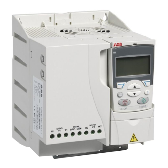
28 Operation principle and hardware description Product overview Layout The layout of the drive is presented below. The construction of the different frame sizes R0…R4 varies to some extent. Covers on (R0 and R1) Covers off (R0 and R1) Cooling outlet through top cover 10 EMC filter grounding screw (EMC). -
Page 29: Overview Of Power And Control Connections
Operation principle and hardware description 29 Overview of power and control connections The diagram gives an overview of connections. I/O connections are parameterable. See chapter Application macros on page for I/O connections for the different macros and chapter Electrical installation on page for installation in general. -
Page 30: Type Designation Label
A, B, C, … for product revision number XXXX: Integer starting every week from 0001 5 ABB MRP code of the drive 6 CE marking and C-Tick, C-UL US, RoHS and TÜV NORD marks (the label of your drive shows the valid markings) -
Page 31: Type Designation Key
Operation principle and hardware description 31 Type designation key The type designation contains information on the specifications and configuration of the drive. You find the type designation on the type designation label attached to the drive. The first digits from the left express the basic configuration, for example ACS355-03E-07A3-4. - Page 32 32 Operation principle and hardware description...
-
Page 33: What This Chapter Contains
Mechanical installation 33 Mechanical installation What this chapter contains The chapter tells how to check the installation site, unpack, check the delivery and install the drive mechanically. Checking the installation site The drive may be installed on the wall or in a cabinet. Check the enclosure requirements for the need to use the NEMA 1 option in wall installations (see chapter Technical data on page 373). -
Page 34: Required Tools
34 Mechanical installation Floor The floor/material below the installation should be non-flammable. Free space around the drive The required free space for cooling above and below the drive is 75 mm (3 in). No free space is required on the sides of the drive, so drives can be mounted immediately next to each other. -
Page 35: Unpacking
Mechanical installation 35 Unpacking The drive (1) is delivered in a package that also contains the following items (frame size R1 shown in the figure): • plastic bag (2) including clamping plate (also used for I/O cables in frame sizes R3 and R4), I/O clamping plate (for frame sizes R0…R2), fieldbus option ground plate, clamps and screws •... -
Page 36: Installing
36 Mechanical installation Installing The instructions in this manual cover drives with the IP20 degree of protection. To comply with NEMA 1, use the MUL1-R1, MUL1-R3 or MUL1-R4 option kit, which is delivered with multilingual installation instructions (3AFE68642868, 3AFE68643147 or 3AUA0000025916, respectively). To obtain a higher degree of protection, the drive must be installed inside a cabinet. - Page 37 Mechanical installation 37 On DIN rail 1. Click the drive to the rail. To detach the drive, press the release lever on top of the drive (1b).
-
Page 38: Fasten Clamping Plates
38 Mechanical installation Fasten clamping plates Note: Make sure that you do not throw the clamping plates away as they are required for proper grounding of the power and control cables as well as the fieldbus option. 1. Fasten the clamping plate (A) to the plate at the bottom of the drive with the provided screws. -
Page 39: What This Chapter Contains
Note: The installation must always be designed and made according to applicable local laws and regulations. ABB does not assume any liability whatsoever for any installation which breaches the local laws and/or other regulations. Furthermore, if the recommendations given by ABB are not followed, the drive may experience problems that the warranty does not cover. -
Page 40: Selecting The Supply Disconnecting Device (Disconnecting Means)
40 Planning the electrical installation Selecting the supply disconnecting device (disconnecting means) Install a hand-operated supply disconnecting device (disconnecting means) between the AC power source and the drive. The disconnecting device must be of a type that can be locked to the open position for installation and maintenance work. ... -
Page 41: Selecting The Power Cables
Planning the electrical installation 41 When more than 4 motors need to be controlled by one drive, contact your local ABB representative. Selecting the power cables General rules Dimension the input power and motor cables according to local regulations. -
Page 42: Alternative Power Cable Types
42 Planning the electrical installation Alternative power cable types Power cable types that can be used with the drive are presented below. Motor cables Note: A separate PE conductor is required if the conductivity of the cable shield is not (recommended for input cables also) sufficient for the purpose. -
Page 43: Additional Us Requirements
Planning the electrical installation 43 Additional US requirements Type MC continuous corrugated aluminum armor cable with symmetrical grounds or shielded power cable is recommended for the motor cables if metallic conduit is not used. The power cables must be rated for 75 °C (167 °F). Conduit Where conduits must be coupled together, bridge the joint with a ground conductor bonded to the conduit on each side of the joint. -
Page 44: Selecting The Control Cables
ABB. Control panel cable In remote use, the cable connecting the control panel to the drive must not exceed 3 m (10 ft). The cable type tested and approved by ABB is used in control panel option kits. -
Page 45: Routing The Cables
Planning the electrical installation 45 Routing the cables Route the motor cable away from other cable routes. Motor cables of several drives can be run in parallel installed next to each other. It is recommended that the motor cable, input power cable and control cables are installed on separate trays. Avoid long parallel runs of motor cables with other cables to decrease electromagnetic interference caused by the rapid changes in the drive output voltage. -
Page 46: Against Thermal Overload
46 Planning the electrical installation Protecting the drive, input power cable, motor and motor cable in short-circuit situations and against thermal overload Protecting the drive and input power cable in short-circuit situations Arrange the protection according to the following guidelines. Circuit diagram Short-circuit protection Protect the drive and input... -
Page 47: Protecting The Motor Against Thermal Overload
Planning the electrical installation 47 Protecting the motor against thermal overload According to regulations, the motor must be protected against thermal overload and the current must be switched off when overload is detected. The drive includes a motor thermal protection function that protects the motor and switches off the current when necessary. -
Page 48: Protecting The Contacts Of Relay Outputs
48 Planning the electrical installation Protecting the contacts of relay outputs Inductive loads (relays, contactors, motors) cause voltage transients when switched off. Equip inductive loads with noise attenuating circuits (varistors, RC filters [AC] or diodes [DC]) in order to minimize the EMC emission at switch-off. If not suppressed, the disturbances may connect capacitively or inductively to other conductors in the control cable and form a risk of malfunction in other parts of the system. -
Page 49: What This Chapter Contains
Electrical installation 49 Electrical installation What this chapter contains The chapter tells how to check the insulation of the assembly and the compatibility with IT (ungrounded) and corner-grounded TN systems as well as connect power cables and control cables. WARNING! The work described in this chapter may only be carried out by a qualified electrician. -
Page 50: Motor And Motor Cable
Protective Earth conductor using a measuring voltage of 500 V DC. The insulation resistance of an ABB motor must exceed 100 Mohm (reference value at 25 °C or 77 °F). For the insulation resistance of other motors, please consult the manufacturer’s instructions. -
Page 51: Connecting The Power Cables
Electrical installation 51 Connecting the power cables Connection diagram Drive INPUT OUTPUT U1/L V1/N W1 BRK+ BRK- U2 V2 W2 For alternatives, see section Selecting the supply disconnecting Optional brake device resistor or (disconnecting Motor Common DC means) on page L1/L L2/N L3 Ground the other end of the PE conductor at the distribution board. -
Page 52: Connection Procedure
52 Electrical installation Connection procedure 1. Strip the input power cable. Ground the bare shield of the cable (if any) 360 degrees under the grounding clamp. Fasten the grounding conductor (PE) of the input power cable under the grounding clamp. Connect the phase conductors to the U1, V1 and W1 terminals. -
Page 53: Connecting The Control Cables
Electrical installation 53 Connecting the control cables I/O terminals The figure below shows the I/O terminals. Tightening torque is 0.4 N·m / 3.5 lbf·in. X1C:STO X1A: X1B: 1 2 3 4 1: SCR 17: ROCOM 2: AI1 18: RONC 3: GND 19: RONO 4: +10 V... - Page 54 54 Electrical installation Voltage and current connection for analog inputs Bipolar voltage (-10…10 V) and current (-20…20 mA) are also possible. If a bipolar connection is used instead of a unipolar one, see section Programmable analog inputs on page for how to set parameters accordingly. Unipolar voltage Bipolar voltage Unipolar/Bipolar current...
-
Page 55: Default I/O Connection Diagram
9902 APPLIC MACRO. The default macro is the ABB standard macro. It provides a general purpose I/O configuration with three constant speeds. Parameter values are the default values given in section Default values with different macros on page 180. - Page 56 56 Electrical installation The default I/O connections for the ABB standard macro are given in the figure below. Signal cable shield (screen) Output frequency reference: 0…10 V 1…10 kohm Analog input circuit common +10V Reference voltage: +10 V DC, max. 10 mA Not in use by default.
-
Page 57: Connection Procedure
Electrical installation 57 Connection procedure 1. Remove the terminal cover by simultaneously pushing the recess and sliding the cover off the frame. 2. Analog signals: Strip the outer insulation of the analog signal cable 360 degrees and ground the bare shield under the clamp. 3. - Page 58 58 Electrical installation...
-
Page 59: What This Chapter Contains
Installation checklist 59 Installation checklist What this chapter contains This chapter contains a list for checking the mechanical and electrical installation of the drive. Checking the installation Check the mechanical and electrical installation of the drive before start-up. Go through the checklist below together with another person. Read chapter Safety page of this manual before you work on the drive. - Page 60 60 Installation checklist Check The drive is grounded properly. The input power voltage matches the drive nominal input voltage. The input power connections at U1/L, V1/N and W1 are OK and tightened with the correct torque. Appropriate input power fuses and disconnector are installed. The motor connections at U2, V2 and W2 are OK and tightened with the correct torque.
-
Page 61: What This Chapter Contains
Start-up, control with I/O and ID run 61 Start-up, control with I/O and ID run What this chapter contains The chapter tells how to: • perform the start-up • start, stop, change the direction of the motor rotation and adjust the speed of the motor through the I/O interface •... -
Page 62: Starting Up The Drive
62 Start-up, control with I/O and ID run Starting up the drive WARNING! The start-up may only be carried out by a qualified electrician. The safety instructions given in chapter Safety on page must be followed during the start-up procedure. The drive will start up automatically at power-up if the external run command is on and the drive is in the remote control mode. -
Page 63: Performing A Manual Start-Up
Start-up, control with I/O and ID run 63 Performing a manual start-up For the manual start-up, you can use the basic control panel or the assistant control panel. The instructions below are valid for both control panels, but the displays shown are the basic control panel displays, unless the instruction applies to the assistant control panel only. - Page 64 Note: Set the motor data to exactly the same value as on Asynchronous motor nameplate example: the motor nameplate. For example, if the motor nominal ABB Motors speed is 1470 rpm on the nameplate, setting the value of motor M2AA 200 MLA 4...
- Page 65 Start-up, control with I/O and ID run 65 Permanent magnet synchronous motor nameplate example: • motor nominal voltage (parameter 9905). 9905 For permanent magnet synchronous motors, enter the back emf voltage at nominal speed here. Otherwise use nominal voltage and perform ID run. If the voltage is given as voltage per rpm, eg, 60 V per 1000 rpm, the voltage for 3000 rpm nominal ·...
- Page 66 66 Start-up, control with I/O and ID run Select the motor identification method (parameter 9910). The default value 0 (OFF/IDMAGN) using the identification magnetization is suitable for most applications. It is applied in this basic start-up procedure. Note however that this requires that parameter 9904 is set to 1 (VECTOR:...
- Page 67 Start-up, control with I/O and ID run 67 • Invert the phases by changing the value of 9914 parameter 9914 to the opposite, ie, from 0 (NO) to 1 (YES), or vice versa. • Verify your work by applying input power and repeating the check as described above.
-
Page 68: Performing A Guided Start-Up
68 Start-up, control with I/O and ID run Performing a guided start-up To be able to perform the guided start-up, you need the assistant control panel. Guided start-up is applicable to AC induction motors. Before you start, ensure that you have the motor nameplate data on hand. POWER-UP Apply input power. - Page 69 Start-up, control with I/O and ID run 69 Select the application macro according to which the PAR EDIT control cables are connected. 9902 APPLIC MACRO ABB STANDARD 00:00 EXIT SAVE Continue with the application set-up. After CHOICE Do you want to...
-
Page 70: Controlling The Drive Through The I/O Interface
Default I/O connection diagram on page according to the connection diagram given for the ABB standard macro. Ensure that the drive is in remote control. Press key In remote control, the panel display shows text REM. to switch between remote and local control. -
Page 71: Performing The Id Run
Start-up, control with I/O and ID run 71 Performing the ID run The drive estimates motor characteristics automatically when the drive is started for the first time and after any motor parameter (group 99 START-UP DATA) is changed. This is valid when parameter 9910 ID RUN has value 0 (OFF/IDMAGN). - Page 72 72 Start-up, control with I/O and ID run ID RUN WITH THE BASIC CONTROL PANEL Change parameter 9910 ID RUN to 1 (ON). Save 9910 the new setting by pressing If you want to monitor actual values during the ID run, go to the Output mode by pressing repeatedly until you get there.
- Page 73 Start-up, control with I/O and ID run 73 After the ID run is completed, the alarm display is FAULT not shown any more. FAULT 11 If the ID run fails, the fault display presented on ID RUN FAIL the right is shown. 00:00...
- Page 74 74 Start-up, control with I/O and ID run...
-
Page 75: What This Chapter Contains
Control panels 75 Control panels What this chapter contains The chapter describes the control panel keys, LED indicators and display fields. It also instructs in using the panel in control, monitoring and changing the settings. About control panels Use a control panel to control the ACS355, read status data, and adjust parameters. The drive works with either of two different control panel types: •... -
Page 76: Applicability
2.04 or later To find out the panel revision, see the label on the back of the panel. An example label and explanation of the label contents are shown below. ABB Oy, ACS-CP-A S/N M0935E0001 RoHS 1 Panel type code... -
Page 77: Overview
Control panels 77 Overview The following table summarizes the key functions and displays on the basic control panel. No. Use LCD display – Divided into five areas: a. Upper left – Control location: LOC: drive control is local, that is, from the control panel OUTPUT REM: drive control is remote, such as the drive... -
Page 78: Operation
78 Control panels Operation You operate the control panel with the help of menus and keys. You select an option, eg, operation mode or parameter, by scrolling the arrow keys until the option is visible in the display and then pressing the key. - Page 79 Control panels 79 How to find out the panel firmware version Step Action Display If the power is switched on, switch it off. Keep key pressed down while you switch on the X X X power and read the panel firmware version shown on the display.
-
Page 80: Output Mode
80 Control panels How to change the direction of the motor rotation You can change the direction of the motor rotation in any mode. Step Action Display If the drive is in remote control (REM shown on the left), switch to local control by pressing . -
Page 81: Reference Mode
Control panels 81 Reference mode In the Reference mode, you can: • set the speed, frequency or torque reference • start, stop, change the direction and switch between local and remote control. How to set the speed, frequency or torque reference Step Action Display... -
Page 82: Parameter Mode
82 Control panels Parameter mode In the Parameter mode, you can: • view and change parameter values • select and modify the signals shown in the Output mode • start, stop, change the direction and switch between local and remote control. How to select a parameter and change its value Step Action Display... - Page 83 By default, the display shows three signals. Signal 1: 0102 SPEED for macros 3-wire, Alternate, Motor potentiometer, Hand/Auto and PID control; 0103 OUTPUT FREQ for macros ABB standard and Torque control Signal 2: 0104 CURRENT Signal 3: 0105 TORQUE.
-
Page 84: Copy Mode
84 Control panels Step Action Display Select the scalings for the signals by specifying the minimum and maximum display values. This has no effect if parameter 3404/3411/3418 is set to 9 (DIRECT). For details, see parameters 3406 3407. 5000 Signal 1: parameters 3406 OUTPUT1 MIN 3407 OUTPUT1 MAX... -
Page 85: Basic Control Panel Alarm Codes
Control panels 85 How to upload and download parameters For the upload and download functions available, see above. Note that the drive has to be in local control for uploading and downloading. Step Action Display Go to the Main menu by pressing if you are in the Output mode, otherwise by pressing repeatedly until you see MENU at the bottom. -
Page 86: Assistant Control Panel
86 Control panels Assistant control panel Features The assistant control panel features: • alphanumeric control panel with an LCD display • language selection for the display • Start-up assistant to ease drive commissioning • copy function – parameters can be copied to the control panel memory for later transfer to other drives or for backup of a particular system. -
Page 87: Overview
Control panels 87 Overview The following table summarizes the key functions and displays on the assistant control panel. No. Use Status LED – Green for normal operation. If LED is flashing, or red, see section LEDs on page 372. 49.1Hz 49 1 Hz LCD display –... -
Page 88: Operation
88 Control panels Status line The top line of the LCD display shows the basic status information of the drive. 49.1Hz MAIN MENU No. Field Alternatives Significance Control location Drive control is local, that is, from the control panel. Drive control is remote, such as the drive I/O or fieldbus. - Page 89 Control panels 89 Initially, the panel is in the Output mode, where you can 49.1Hz 49 1 Hz start, stop, change the direction, switch between local and 0 5 A remote control, modify the reference value and monitor up 10 7 % to three actual values.
- Page 90 90 Control panels How to get help Step Action Display Press to read the context-sensitive help text for the PAR GROUPS item that is highlighted. 01 OPERATING DATA 03 FB ACTUAL SIGNALS 04 FAULT HISTORY 10 START/STOP/DIR 11 REFERENCE SELECT EXIT 00:00 If help text exists for the item, it is shown on the display.
- Page 91 Control panels 91 How to start, stop and switch between local and remote control You can start, stop and switch between local and remote control in any mode. To be able to start or stop the drive, the drive must be in local control. Step Action Display •...
-
Page 92: Output Mode
92 Control panels Output mode In the Output mode, you can: • monitor actual values of up to three signals in group 01 OPERATING DATA • change the direction of the motor rotation • set the speed, frequency or torque reference •... -
Page 93: Parameters Mode
Control panels 93 How to set the speed, frequency or torque reference Step Action Display EXIT If you are not in the Output mode, press repeatedly 49.1Hz until you get there. 49 1 Hz 0 5 A 10 7 % 00:00 MENU If the drive is in remote control (REM shown on the status... - Page 94 EXIT Select the appropriate parameter with keys PARAMETERS . The current value of the parameter is shown 9901 LANGUAGE 9902 APPLIC MACRO below the selected parameter. ABB STANDARD 9903 MOTOR TYPE 9904 MOTOR CTRL MODE EXIT 00:00 EDIT EDIT Press...
- Page 95 00:00 SAVE Signal 1: 0102 SPEED for macros 3-wire, Alternate, PAR EDIT Motor potentiometer, Hand/Auto and PID control; 0103 OUTPUT FREQ for macros ABB standard and 3408 SIGNAL2 PARAM CURRENT Torque control Signal 2: 0104 CURRENT [104] Signal 3: 0105 TORQUE.
-
Page 96: Assistants Mode
96 Control panels Assistants mode When the drive is first powered up, the Start-up assistant guides you through the setup of the basic parameters. The Start-up assistant is divided into assistants, each of which is responsible for the specification of a related parameter set, for example Motor set-up or PID control. - Page 97 Control panels 97 Step Action Display • To specify a new value, press keys PAR EDIT 9905 MOTOR NOM VOLT 240 V 00:00 EXIT SAVE • To ask for information on the requested parameter, HELP press key . Scroll the help text with keys Set as given on the EXIT motor nameplate.
-
Page 98: Changed Parameters Mode
98 Control panels Changed parameters mode In the Changed parameters mode, you can: • view a list of all parameters that have been changed from the macro default values • change these parameters • start, stop, change the direction and switch between local and remote control. How to view and edit changed parameters Step Action... -
Page 99: Fault Logger Mode
Control panels 99 Fault logger mode In the Fault logger mode, you can: • view the drive fault history of maximum ten faults (after a power off, only the three latest faults are kept in the memory) • see the details of the three latest faults (after a power off, the details of only the most recent fault is kept in the memory) •... -
Page 100: Time And Date Mode
100 Control panels Time and date mode In the Time and date mode, you can: • show or hide the clock • change date and time display formats • set the date and time • enable or disable automatic clock transitions according to the daylight saving changes •... - Page 101 Control panels 101 Step Action Display • To set the time, select SET TIME on the menu and SET TIME press . Specify the hours with keys , and press .Then specify the minutes. Press 15:41 CANCEL to save or to cancel your changes.
-
Page 102: Parameter Backup Mode
102 Control panels Parameter backup mode The Parameter backup mode is used to export parameters from one drive to another or to make a backup of the drive parameters. Uploading to the panel stores all drive parameters, including up to three user sets, to the assistant control panel. The full set, partial parameter set (application) and user sets can then be downloaded from the control panel to another drive or the same drive. - Page 103 Control panels 103 How to upload and download parameters For the upload and download functions available, see above. Note that the drive has to be in local control for uploading and downloading. Step Action Display MENU Go to the Main menu by pressing if you are in the MAIN MENU EXIT...
- Page 104 104 Control panels How to view information about the backup Step Action Display MENU Go to the Main menu by pressing if you are in the MAIN MENU EXIT Output mode, otherwise by pressing repeatedly until PARAMETERS you get to the Main menu. ASSISTANTS CHANGED PAR EXIT...
-
Page 105: I/O Settings Mode
Control panels 105 I/O settings mode In the I/O settings mode, you can: • check the parameter settings related to any I/O terminal • edit the parameter setting. For example, if “1103: REF1” is listed under Ain1 (Analog input 1), that is, parameter 1103 REF1 SELECT has value AI1, you can change its value to, eg, AI2. - Page 106 106 Control panels...
-
Page 107: What This Chapter Contains
Macro Suitable applications ABB standard Ordinary speed control applications where no, one, two or three constant speeds are used. Start/stop is controlled with one digital input (level start and stop). It is possible to switch between two acceleration and deceleration times. - Page 108 108 Application macros Macro Suitable applications Hand/Auto Speed control applications where switching between two control devices is needed. Some control signal terminals are reserved for one device, the rest for the other. One digital input selects between the terminals (devices) in use.
-
Page 109: Summary Of The I/O Connections Of The Application Macros
Application macros 109 Summary of the I/O connections of the application macros The following table gives the summary of the default I/O connections of all application macros. Input/ Macro output 3-wire Alternate Motor Hand/Auto PID Torque standard potentiom. control control Freq. -
Page 110: Abb Standard Macro
110 Application macros ABB standard macro This is the default macro. It provides a general purpose I/O configuration with three constant speeds. Parameter values are the default values given in section Parameters on page 191. If you use other than the default connections presented below, see section terminals on page 53. -
Page 111: Wire Macro
Application macros 111 3-wire macro This macro is used when the drive is controlled using momentary push-buttons. It provides three constant speeds. To enable the macro, set the value of parameter 9902 APPLIC MACRO to 2 (3-WIRE). For the parameter default values, see section Default values with different macros page 180. -
Page 112: Alternate Macro
112 Application macros Alternate macro This macro provides an I/O configuration adapted to a sequence of DI control signals used when alternating the rotation direction of the motor. To enable the macro, set the value of parameter 9902 APPLIC MACRO to 3 (ALTERNATE). -
Page 113: Motor Potentiometer Macro
Application macros 113 Motor potentiometer macro This macro provides a cost-effective interface for PLCs that vary the speed of the motor using only digital signals. To enable the macro, set the value of parameter 9902 APPLIC MACRO to 4 (MOTOR POT). -
Page 114: Hand/Auto Macro
114 Application macros Hand/Auto macro This macro can be used when switching between two external control devices is needed. To enable the macro, set the value of parameter 9902 APPLIC MACRO 5 (HAND/AUTO). For the parameter default values, see section Default values with different macros page 180. -
Page 115: Pid Control Macro
Application macros 115 PID control macro This macro provides parameter settings for closed-loop control systems such as pressure control, flow control, etc. Control can also be switched to speed control using a digital input. To enable the macro, set the value of parameter 9902 APPLIC MACRO to 6... -
Page 116: Torque Control Macro
116 Application macros Torque control macro This macro provides parameter settings for applications that require torque control of the motor. Control can also be switched to speed control using a digital input. To enable the macro, set the value of parameter 9902 APPLIC MACRO to 8 (TORQUE... -
Page 117: Ac500 Modbus Macro
Application macros 117 AC500 Modbus macro The AC500 Modbus application macro configures the ACS355 drive communication and control parameters to be applicable with the pre-engineered Starter kit for AC500-eCo PLC and ACS355 drive over STD Modbus connection (FMBA-01 adapter). The macro is available in ACS355 drives with firmware version 5.03C or later. To activate the macro, set parameter 9902 APPLIC MACRO to AC500 MODBUS... - Page 118 118 Application macros The AC500 Modbus application macro default values for the drive parameters correspond to the ABB standard macro (parameter 9902, value 1 (ABB STANDARD), see section ABB standard macro on page 110), with the following differences: Name Default value...
-
Page 119: User Macros
Application macros 119 User macros In addition to the standard application macros, it is possible to create three user macros. The user macro allows the user to save the parameter settings, including group 99 START-UP DATA, and the results of the motor identification into the permanent memory and recall the data at a later time. - Page 120 120 Application macros...
-
Page 121: What This Chapter Contains
Program features 121 Program features What this chapter contains The chapter describes program features. For each feature, there is a list of related user settings, actual signals, and fault and alarm messages. Start-up assistant Introduction The Start-up assistant (requires the assistant control panel) guides the user through the start-up procedure, helping to enter the requested data (parameter values) to the drive. -
Page 122: Default Order Of The Tasks
MACRO), the Start-up assistant decides which consequent tasks it suggests. The default tasks are shown in the table below. Application selection Default tasks ABB STANDARD Language select, Motor set-up, Application, Option modules, Speed control EXT1, Speed control EXT2, Start/Stop control, Timed functions, Protections, Output signals... -
Page 123: List Of The Tasks And The Relevant Drive Parameters
Program features 123 List of the tasks and the relevant drive parameters Depending on the selection made in the Application task (parameter 9902 APPLIC MACRO), the Start-up assistant decides which consequent tasks it suggests. Name Description Set parameters Language select Selecting the language 9901 Motor set-up... - Page 124 124 Program features Name Description Set parameters Start/Stop control Selecting the source for start and stop 1001, 1002 signals of the two external control locations, EXT1 and EXT2 Selecting between EXT1 and EXT2 1102 Defining the direction control 1003 Defining the start and stop modes 2101…2103 Selecting the use of Run enable signal 1601...
-
Page 125: Contents Of The Assistant Displays
Program features 125 Contents of the assistant displays There are two types of displays in the Start-up assistant: Main displays and information displays. The main displays prompt the user to feed in information. The assistant steps through the main displays. The information displays contain help texts for the main displays. -
Page 126: Local Control Vs. External Control
126 Program features Local control vs. external control The drive can receive start, stop and direction commands and reference values from the control panel or through digital and analog inputs. Embedded fieldbus or an optional fieldbus adapter enables control over an open fieldbus link. A PC equipped with the DriveWindow Light 2 PC tool can also control the drive. -
Page 127: External Control
Program features 127 External control When the drive is in external (remote) control, the commands are given through the standard I/O terminals (digital and analog inputs) and/or the fieldbus interface. In addition, it is also possible to set the control panel as the source for the external control. - Page 128 128 Program features Block diagram: Start, stop, direction source for EXT1 The figure below shows the parameters that select the interface for start, stop, and direction for external control location EXT1. Select EXT1 Start/stop/ direction Fieldbus selection See chapters COMM Fieldbus control with Embedded fieldbus...
-
Page 129: Reference Types And Processing
Program features 129 Reference types and processing The drive can accept a variety of references in addition to the conventional analog input and control panel signals. • The drive reference can be given with two digital inputs: One digital input increases the speed, the other decreases it. -
Page 130: Reference Trimming
130 Program features Reference trimming In reference trimming, the external reference is corrected depending on the measured value of a secondary application variable. The block diagram below illustrates the function. 1105 REF1 MAX 1108 REF2 MA Switch Select Switch 2 (DIRECT) max. -
Page 131: Example
Program features 131 Example The drive runs a conveyor line. It is speed controlled but the line tension also needs to be taken into account: If the measured tension exceeds the tension setpoint, the speed will be slightly decreased, and vice versa. To accomplish the desired speed correction, the user •... -
Page 132: Programmable Analog Inputs
132 Program features Programmable analog inputs The drive has two programmable analog voltage/current inputs. The inputs can be inverted, filtered and the maximum and minimum values can be adjusted. The update cycle for the analog input is 8 ms (12 ms cycle once per second). The cycle time is shorter when information is transferred to the application program (8 ms ->... -
Page 133: Programmable Analog Output
Program features 133 Programmable analog output One programmable current output (0…20 mA) is available. Analog output signal can be inverted, filtered and the maximum and minimum values can be adjusted. The analog output signals can be proportional to motor speed, output frequency, output current, motor torque, motor power, etc. -
Page 134: Programmable Digital Inputs
134 Program features Programmable digital inputs The drive has five programmable digital inputs. The update time for the digital inputs is 2 ms. One digital input (DI5) can be programmed as a frequency input. See section Frequency input on page 135. ... -
Page 135: Programmable Relay Output
Program features 135 Programmable relay output The drive has one programmable relay output. It is possible to add three additional relay outputs with the optional MREL-01 output relay module. For more information, see MREL-01 output relay module user's manual (3AUA0000035974 [English]). With a parameter setting it is possible to choose what information to indicate through the relay output: Ready, running, fault, alarm, etc. -
Page 136: Transistor Output
136 Program features Transistor output The drive has one programmable transistor output. The output can be used either as a digital output or frequency output (0…16000 Hz). The update time for the transistor/frequency output is 2 ms. Settings Parameter Additional information Group 18 FREQ IN &... -
Page 137: Diagnostics
Program features 137 Diagnostics Actual signal Additional information Groups 01 OPERATING DATA … Lists of actual signals 04 FAULT HISTORY Motor identification The performance of vector control is based on an accurate motor model determined during the motor start-up. A motor Identification magnetization is automatically performed the first time the start command is given. -
Page 138: Power Loss Ride-Through
138 Program features Power loss ride-through If the incoming supply voltage is cut off, the drive will continue to operate by utilizing the kinetic energy of the rotating motor. The drive will be fully operational as long as the motor rotates and generates energy to the drive. The drive can continue the operation after the break if the main contactor remained closed. -
Page 139: Maintenance Trigger
Program features 139 Maintenance trigger A maintenance trigger can be activated to show a notice on the panel display when, eg, drive power consumption has exceeded the defined trigger point. Settings Parameter group 29 MAINTENANCE TRIG DC hold With the motor DC hold feature, it is possible Motor speed DC hold to lock the rotor at zero speed. -
Page 140: Flux Braking
140 Program features Flux braking The drive can provide greater deceleration by raising the level of magnetization in the motor. By increasing the motor flux, the energy generated by the motor during braking can be converted to motor thermal energy. Motor speed = Braking torque = 100 N·m... -
Page 141: Settings
Program features 141 The drive monitors the motor status continuously, also during the Flux braking. Therefore, Flux braking can be used both for stopping the motor and for changing the speed. The other benefits of Flux braking are: • The braking starts immediately after a stop command is given. The function does not need to wait for the flux reduction before it can start the braking. -
Page 142: Critical Speeds
142 Program features Critical speeds Critical speeds function is available for applications where it is necessary to avoid certain motor speeds or speed bands because of, eg, mechanical resonance problems. The user can define three critical speeds or speed bands. ... -
Page 143: Custom U/F Ratio
Program features 143 Custom U/f ratio The user can define a U/f curve (output voltage as a function of frequency). This custom ratio is used only in special applications where linear and squared U/f ratio are not sufficient (eg, when motor break-away torque needs to be boosted). Voltage (V) Custom U/f ratio Par. -
Page 144: Speed Controller Tuning
144 Program features Speed controller tuning It is possible to manually adjust the controller gain, integration time and derivation time, or let the drive perform a separate speed controller Autotune run (parameter 2305 AUTOTUNE RUN). In Autotune run, the speed controller is tuned based on the load and inertia of the motor and the machine. -
Page 145: Settings
Program features 145 Settings Parameter groups 23 SPEED CONTROL 20 LIMITS Diagnostics Actual signal 0102 SPEED Speed control performance figures The table below shows typical performance figures for speed control. load Speed No pulse With pulse control encoder encoder Static 20% of motor... -
Page 146: Torque Control Performance Figures
146 Program features Torque control performance figures The drive can perform precise torque control without any speed feedback from the motor shaft. The table below shows typical performance figures for torque control. Torque No pulse With pulse control encoder encoder Non-linearity ±... -
Page 147: Ir Compensation For A Scalar Controlled Drive
Program features 147 IR compensation for a scalar controlled drive IR compensation is active only when the motor Motor voltage control mode is scalar (see section Scalar control on page 146). When IR compensation is IR compensation activated, the drive gives an extra voltage boost to the motor at low speeds. -
Page 148: Motor Thermal Protection
148 Program features Settings Parameters 3010 STALL FUNCTION, 3011 STALL FREQUENCY 3012 STALL TIME Motor thermal protection The motor can be protected against overheating by activating the Motor thermal protection function. The drive calculates the temperature of the motor on the basis of the following assumptions: •... -
Page 149: Earth Fault Protection
Program features 149 Settings Parameters 3013 UNDERLOAD FUNC, 3014 UNDERLOAD TIME 3015 UNDERLOAD CURVE Earth fault protection The Earth fault protection detects earth faults in the motor or motor cable. The protection can be selected to be active during start and run or during start only. An earth fault in the input power line does not activate the protection. -
Page 150: Short-Circuit
150 Program features Short-circuit If a short-circuit occurs, the drive will not start and a fault indication is given. Internal fault If the drive detects an internal fault, the drive is stopped and a fault indication is given. Operation limits The drive has adjustable limits for speed, current (maximum), torque (maximum) and DC voltage. -
Page 151: Supervisions
Program features 151 Supervisions The drive monitors whether certain user selectable variables are within the user- defined limits. The user may set limits for speed, current etc. The supervision status can be indicated through relay or digital output. The supervision functions operate on a 2 ms time level. ... -
Page 152: Process Controller Pid1
152 Program features Process controller PID1 PID1 has two separate sets of parameters (40 PROCESS PID SET 41 PROCESS PID SET 2). Selection between parameter sets 1 and 2 is defined by a parameter. In most cases when there is only one transducer signal wired to the drive, only parameter set 1 is needed. - Page 153 Program features 153 The following figure presents the speed/scalar control block diagram for process controller PID1.
-
Page 154: Settings
154 Program features Settings Parameter Additional information 1101 Local control mode reference type selection 1102 EXT1/EXT2 selection 1106 PID1 activation 1107 REF2 minimum limit 1501 PID2 output (external controller) connection to AO 9902 PID control macro selection Groups 40 PROCESS PID SET PID1 settings 1…41 PROCESS PID SET 2 Group... -
Page 155: Sleep Function For The Process Pid (Pid1) Control
Program features 155 Sleep function for the process PID (PID1) control The sleep function operates on a 2 ms time level. The block diagram below illustrates the sleep function enable/disable logic. The sleep function can be put into use only when the PID control is active. Switch Compare Select... -
Page 156: Example
156 Program features Example The time scheme below visualizes the operation of the sleep function. Motor speed = Sleep delay (4024) t<t Control panel display: Sleep level PID SLEEP (4023) Stop Start Actual value Wake-up delay (4026) Wake-up deviation (4025) Sleep function for a PID controlled pressure boost pump (when parameter 4022... -
Page 157: Diagnostics
Program features 157 Diagnostics Parameter Additional information 1401 PID sleep function status through RO 1 1402/1403/1410 PID sleep function status through RO 2…4. With option MREL-01 only. Alarm Additional information PID SLEEP Sleep mode Motor temperature measurement through the standard I/O This section describes the temperature measurement of one motor when the drive I/O terminals are used as the connection interface. -
Page 158: Settings
158 Program features It is also possible to monitor motor temperature by connecting a PTC sensor and a thermistor relay between the +24 V DC voltage supply offered by the drive and a digital input. The figure below displays the connection. Par. -
Page 159: Control Of A Mechanical Brake
Program features 159 Control of a mechanical brake The mechanical brake is used for holding the motor and driven machinery at zero speed when the drive is stopped, or not powered. Example The figure below shows a brake control application example. WARNING! Make sure that the machinery into which the drive with brake control function is integrated fulfills the personnel safety regulations. -
Page 160: Operation Time Scheme
160 Program features Operation time scheme The time scheme below illustrates the operation of the brake control function. See also section State shifts on page 161. Start command External speed reference Inverter modulating Motor magnetized Open brake command (RO/DO) Internal speed reference (actual motor speed) -
Page 161: State Shifts
Program features 161 State shifts From any state (rising edge) 0/0/1 MODULATION OPEN 1/1/0 BRAKE RELEASE RFG 1/1/0 INPUT RFG INPUT 1/1/1 TO ZERO CLOSE 0/1/1 BRAKE RFG = Ramp function generator in the speed control loop (reference handling). X/Y/Z State (Symbol - NN: State name... -
Page 162: Settings
162 Program features Settings Parameter Additional information 1401/1805 Mechanical brake activation through RO 1 / DO 1402/1403/1410 Mechanical brake activation through RO 2…4. With option MREL-01 only. 2112 Zero speed delay Group 43 MECH BRK CONTROL Brake function settings Jogging The jogging function is typically used to control a cyclical movement of a machine section. - Page 163 Program features 163 The function operates on a 2 ms time level Speed 10 11 12 13 14 15 16 Phase Jog Start Description Drive accelerates to the jogging speed along the acceleration ramp of the jogging function. Drive runs at the jogging speed. Drive decelerates to zero speed along the deceleration ramp of the jogging function.
-
Page 164: Settings
164 Program features It is also possible to activate jogging function 1 or 2 through fieldbus. Jogging function 1 uses constant speed 7 and jogging function 2 uses constant speed 6. Both functions use acceleration/deceleration ramp pair 2. Settings Parameter Additional information 1010... -
Page 165: Real-Time Clock And Timed Functions
Program features 165 Real-time clock and timed functions Real-time clock The real-time clock has the following features: • four daily times • four weekly times • timed boost function, eg, a constant speed which is on for a certain pre- programmed time. - Page 166 166 Program features Use the control panel to configure the timer in four stages: 1. Enable the timer. Configure how the timer is activated. The timer can be enabled from one of the digital inputs or inverted digital inputs. 2. Set the time period. Define the start and stop times and start and stop day when the timer operates.
-
Page 167: Example
Program features 167 A parameter which is triggered by a timed function can be connected to only one timed function at a time. 1001 EXT1 COMMANDS Timed function 1 1002 EXT2 COMMANDS 3626 TIMED FUNC 1 SRC 1102 EXT1/EXT2 SEL 1201 CONST SPEED SEL Timed function 2 1209 TIMED MODE SEL... -
Page 168: Settings
168 Program features Settings Parameter Additional information 36 TIMED FUNCTIONS Timed functions settings 1001, 1002 Timed start/stop control 1102 Timed EXT1/EXT2 selection 1201 Timed constant speed 1 activation 1209 Timed speed selection 1401 Timed function status indicated through relay output RO 1 1402/1403/1410 Timed function status indicated through relay output RO 2…4. -
Page 169: Counter
Program features 169 Counter Drive start and stop can be controlled with counter functions. The counter function can also be used as state change trigger signal in Sequence programming. See section Sequence programming on page 169. Settings Parameter Additional information 1001, 1002 Start/Stop signal sources... -
Page 170: Settings
170 Program features Note: By default all Sequence programming parameters can be changed even when the Sequence programming is active. It is recommended that after the Sequence programming parameters are set, parameters are locked with parameter 1602 PARAMETER LOCK. Settings Parameter Additional information... -
Page 171: State Shifts
Program features 171 State shifts Sequence programming 0167 bit 0 = 1 ENABLE STATE 1 0168 = 1 (State 1) (par. 8420…8424) Go to state N (par 8426, 8427)* Go to state 2 (par 8425)* STATE 2 0168 = 2 (State 2) State N (par. -
Page 172: Example 1
172 Program features Example 1 50 Hz 0 Hz -50 Hz Seq. start State change trigger Sequence programming is activated by digital input DI1. ST1: Drive is started in reverse direction with -50 Hz reference and 10 s ramp time. State 1 is active for 40 s. -
Page 173: Example 2
Program features 173 Additional information Par. Setting Par. Setting Par. Setting Par. Setting 8420 ST1 REF 100% 8430 40% 8440 50% 8450 100% State reference 8421 ST1 START 8431 START 8441 START 8451 START Run, direction COMMANDS and stop command 8422 ST1 10 s 8432 60 s... - Page 174 174 Program features ST1: Drive is started in forward direction with AI1 (AI1 + 50% - 50%) reference and ramp pair 2. State shifts to the next state when reference is reached. All relay and analog outputs are cleared. ST2: Drive is accelerated with AI1 + 15% (AI1 + 65% - 50%) reference and 1.5 s ramp time.
- Page 175 Program features 175 Parameter Setting Additional information 1002 EXT2 COMMANDS SEQ PROG Start, stop, direction commands for EXT2 1102 EXT1/EXT2 SEL EXT2 EXT2 activation 1106 REF2 SELECT AI1+SEQ Sequence programming output as REF2 PROG 1201 CONST SPEED SEL NOT SEL Deactivation of constant speeds 1401 RELAY OUTPUT 1 SEQ PROG...
- Page 176 176 Program features Additional information Par. Setting Par. Setting Par. Setting Par. Setting 8420 ST1 REF 8430 65% 8440 60% 8450 35% State reference 8421 ST1 START 8431 START 8441 START 8451 START Run, direction COMMANDS and stop commands 8422 ST1 -0.2 8432 1.5 s 8442 0 s...
-
Page 177: Safe Torque Off (Sto) Function
Program features 177 Additional information Par. Setting Par. Setting Par. Setting Par. Setting 8464 ST5 0.2 s 8474 0 s 8484 0 s 8494 0 s State change CHANGE DLY delay 8465 ST5 ENTER 8475 NOT SEL 8485 NOT SEL 8495 LOGIC TRIG TO ST6... - Page 178 178 Program features...
-
Page 179: What This Chapter Contains
Actual signals and parameters 179 Actual signals and parameters What this chapter contains The chapter describes the actual signals and parameters and gives the fieldbus equivalent values for each signal/parameter. It also contains a table of the default values for the different macros. Terms and abbreviations Term Definition... -
Page 180: Fieldbus Equivalent
180 Actual signals and parameters Fieldbus equivalent Example: If 2017 MAX TORQUE 1 (see page 225) is set from an external control system, an integer value of 1000 corresponds to 100.0%. All the read and sent values are limited to 16 bits (-32768…32767). Storing the parameters All parameter settings are stored automatically to the permanent memory of the drive. - Page 181 In some cases it is desired to control several functions with one input. For example in the ABB standard macro, DI3 and DI4 are set to control constant speeds. On the other hand, it is possible to select value 6 (DI3U,4D) for parameter 1103 REF1 SELECT.
-
Page 182: Differences Between The Default Values In E And U Type Drives
182 Actual signals and parameters Differences between the default values in E and U type drives The type designation label shows the type of the drive, see section Type designation on page 31. The following table lists the differences between the parameter default values in the E and U type drives. -
Page 183: Actual Signals
Actual signals and parameters 183 Actual signals Actual signals Name/Value Description FbEq 01 OPERATING Basic signals for monitoring the drive (read-only) DATA 0101 SPEED & DIR Calculated motor speed in rpm. A negative value indicates 1 = 1 rpm reverse direction. 0102 SPEED Calculated motor speed in rpm 1 = 1 rpm... - Page 184 184 Actual signals and parameters Actual signals Name/Value Description FbEq 0128 PID 1 SETPNT Setpoint signal (reference) for the process PID1 controller. Unit depends on parameter 4006 UNITS, 4007 UNIT SCALE 4027 PID 1 PARAM SET settings. 0129 PID 2 SETPNT Setpoint signal (reference) for the PID2 controller. Unit depends on parameter 4106 UNITS 4107 UNIT SCALE...
- Page 185 Actual signals and parameters 185 Actual signals Name/Value Description FbEq 0144 DRIVE ON Drive control board power-on time in 2 second ticks (30 1 = 2 s TIME LO ticks = 60 seconds). Counter cannot be reset. 0145 MOTOR TEMP Measured motor temperature. Unit depends on the sensor 1 = 1 type selected by group 35 MOTOR TEMP MEAS...
-
Page 186: Fb Actual Signals
186 Actual signals and parameters Actual signals Name/Value Description FbEq 0167 SEQ PROG Status word of the Sequence programming: 1 = 1 Bit 0 = ENABLED (1 = enabled) Bit 1 = STARTED Bit 2 = PAUSED Bit 3 = LOGIC VALUE (logic operation defined by parameters 8406…8410). - Page 187 Actual signals and parameters 187 Actual signals Name/Value Description FbEq 0303 FB STS WORD A 16-bit data word. See section DCU communication profile on page 333. 0304 FB STS WORD A 16-bit data word. See section DCU communication profile on page 0305 FAULT WORD A 16-bit data word.
- Page 188 188 Actual signals and parameters Actual signals Name/Value Description FbEq Bit 14 = MOTOR PHASE Bit 15 = OUTP WIRING 0307 FAULT WORD A 16-bit data word. For the possible causes and remedies and fieldbus equivalents, see chapter Fault tracing on page 349.
-
Page 189: Fault History
Actual signals and parameters 189 Actual signals Name/Value Description FbEq 0309 ALARM WORD A 16-bit data word. For the possible causes and remedies and fieldbus equivalents, see chapter Fault tracing on page 349. An alarm can be reset by resetting the whole alarm word: Write zero to the word. - Page 190 190 Actual signals and parameters Actual signals Name/Value Description FbEq 0406 VOLTAGE AT Intermediate circuit voltage in V DC at the time the latest 1 = 0.1 V fault occurred 0407 CURRENT AT Motor current in A at the time the latest fault occurred 1 = 0.1 A 0408 TORQUE AT Motor torque as a percentage of the motor nominal torque...
-
Page 191: Parameters
Actual signals and parameters 191 Parameters All parameters Name/Value Description Def/FbEq 10 START/STOP/DIR The sources for external start, stop and direction control 1001 EXT1 Defines the connections and the source for the start, stop DI1,2 COMMANDS and direction commands for external control location 1 (EXT1). - Page 192 192 Actual signals and parameters All parameters Name/Value Description Def/FbEq KEYPAD Start, stop and direction commands through control panel when EXT1 is active. To control the direction, parameter 1003 DIRECTION setting must be REQUEST. DI1F,2R Start, stop and direction commands through digital inputs DI1 and DI2.
- Page 193 Actual signals and parameters 193 All parameters Name/Value Description Def/FbEq COUNTR Start when counter limit defined by parameter 1905 START COUNTER LIMIT has been exceeded. Stop with counter stop signal. Source for the signal is selected by parameter 1911 CNTR S/S COMMAND.
-
Page 194: Reference Select
COMM Fieldbus interface as the source for EXT1/EXT2 selection, ie, Control word 0301 FB CMD WORD 1 bit 5 (with ABB drives profile 5319 EFB PAR 19 bit 11). The Control word is sent by the fieldbus controller through the fieldbus adapter or embedded fieldbus (Modbus) to the drive. - Page 195 Actual signals and parameters 195 All parameters Name/Value Description Def/FbEq 1103 REF1 SELECT Selects the signal source for external reference REF1. See section Block diagram: Reference source for EXT1 on page 128. KEYPAD Control panel Analog input AI1 Analog input AI2 AI1/JOYST Analog input AI1 as joystick.
- Page 196 196 Actual signals and parameters All parameters Name/Value Description Def/FbEq COMM+AI1 Summation of fieldbus reference REF1 and analog input AI. See section Reference selection and correction on page 320. COMM*AI1 Multiplication of fieldbus reference REF1 and analog input AI1. See section Reference selection and correction page 320.
- Page 197 Actual signals and parameters 197 All parameters Name/Value Description Def/FbEq SEQ PROG Sequence programming output. See parameter 8420 ST1 SEL. AI1+SEQ Addition of analog input AI1 and Sequence programming PROG output AI2+SEQ Addition of analog input AI2 and Sequence programming PROG output ODVA HZ REF ODVA AC/DC profile speed reference and actual values in...
- Page 198 198 Actual signals and parameters All parameters Name/Value Description Def/FbEq DI3U,4D See parameter 1103 REF1 SELECT. COMM See parameter 1103 REF1 SELECT. COMM+AI1 See parameter 1103 REF1 SELECT. COMM*AI1 See parameter 1103 REF1 SELECT. DI3U,4D(RNC) See parameter 1103 REF1 SELECT. DI3U,4D(NC) See parameter 1103 REF1...
-
Page 199: Constant Speeds
Actual signals and parameters 199 All parameters Name/Value Description Def/FbEq 12 CONSTANT Constant speed selection and values. See section Constant SPEEDS speeds on page 142. 1201 CONST Activates the constant speeds or selects the activation DI3,4 SPEED SEL signal. NOT SEL No constant speed in use Speed defined by parameter 1202 CONST SPEED 1... - Page 200 200 Actual signals and parameters All parameters Name/Value Description Def/FbEq TIMED FUNC 1 External speed reference, speed defined by parameter 1202 CONST SPEED 1 or speed defined by parameter 1203 CONST SPEED 2 is used, depending on the selection of parameter 1209 TIMED MODE SEL and the state of timed function 1.
- Page 201 Actual signals and parameters 201 All parameters Name/Value Description Def/FbEq DI1,2,3(INV) Constant speed selection through inverted digital inputs DI1, DI2 and DI3. 1 = DI active, 0 = DI inactive. DI DI2 DI3 Operation 1 No constant speed 1 Speed defined by par. 1202 CONST SPEED 1 1 Speed defined by par.
- Page 202 202 Actual signals and parameters All parameters Name/Value Description Def/FbEq 1208 CONST Defines constant speed (or drive output frequency) 7. E: 50.0 Hz SPEED 7 Constant speed 7 is used also as jogging speed (see U: 60.0 Hz section Control of a mechanical brake on page 159) or with fault functions (3001 AI<MIN FUNCTION...
-
Page 203: Analog Inputs
Actual signals and parameters 203 All parameters Name/Value Description Def/FbEq CS1/2/3/4 When parameter 1201 CONST SPEED SEL TIMED FUNC 1 … TIMED FUNC 4, this timed function selects a constant speed. 1 = timed function active, 0 = timed function inactive. Timed function 1…4 Operation Speed defined by parameter 1202... - Page 204 204 Actual signals and parameters All parameters Name/Value Description Def/FbEq 1302 MAXIMUM AI1 Defines the maximum %-value that corresponds to 100.0% maximum mA/(V) signal for analog input AI1. When used as a reference, the value corresponds to the reference maximum setting. 0…20 mA 0…100% 4…20 mA...
-
Page 205: Relay Outputs
Actual signals and parameters 205 All parameters Name/Value Description Def/FbEq 14 RELAY OUTPUTS Status information indicated through relay output, and relay operating delays. Note: Relay outputs 2…4 are available only if the MREL-01 output relay module is connected to the drive. See MREL- 01 output relay module user's manual (3AUA0000035974 [English]). - Page 206 206 Actual signals and parameters All parameters Name/Value Description Def/FbEq REF LOSS Reference or active control location is lost. OVERCURRE Alarm/Fault by overcurrent protection function OVERVOLTAG Alarm/Fault by overvoltage protection function DRIVE TEMP Alarm/Fault by drive overtemperature protection function UNDERVOLTA Alarm/Fault by undervoltage protection function AI1 LOSS Analog input AI1 signal is lost.
- Page 207 Actual signals and parameters 207 All parameters Name/Value Description Def/FbEq TIMED FUNC 1 Timed function 1 is active. See parameter group 36 TIMED FUNCTIONS. TIMED FUNC 2 Timed function 2 is active. See parameter group 36 TIMED FUNCTIONS. TIMED FUNC 3 Timed function 3 is active. See parameter group 36 TIMED FUNCTIONS.
-
Page 208: Analog Outputs
208 Actual signals and parameters All parameters Name/Value Description Def/FbEq 1405 RO 1 OFF Defines the release delay for relay output RO 1. 0.0 s DELAY 0.0…3600.0 s Delay time. See the figure for parameter 1404 RO 1 ON 1 = 0.1 s DELAY. -
Page 209: System Controls
Fieldbus interface as the source for inverted Run enable signal (Run disable), ie, Control word 0301 FB CMD WORD bit 6 (with ABB drives profile 5319 EFB PAR 19 bit 3). The Control word is sent by the fieldbus controller through the fieldbus adapter or embedded fieldbus (Modbus) to the drive. - Page 210 COMM Fieldbus interface as the source for the fault reset signal, ie, Control word 0301 FB CMD WORD 1 bit 4 (with ABB drives profile 5319 EFB PAR 19 bit 7). The Control word is sent by the fieldbus controller through the fieldbus adapter or embedded fieldbus (Modbus) to the drive.
- Page 211 Actual signals and parameters 211 All parameters Name/Value Description Def/FbEq DI3(INV) See selection DI1(INV). DI4(INV) See selection DI1(INV). DI5(INV) See selection DI1(INV). 1605 USER PAR Enables the change of the User parameter set through a NOT SEL SET CHG digital input. See parameter 9902 APPLIC MACRO.
- Page 212 212 Actual signals and parameters All parameters Name/Value Description Def/FbEq DI1(INV) User parameter set control through inverted digital input DI1. Falling edge of inverted digital input DI1: User parameter set 2 is loaded into use. Rising edge of inverted digital input DI1: User parameter set 1 is loaded into use. DI2(INV) See selection DI1(INV).
- Page 213 Actual signals and parameters 213 All parameters Name/Value Description Def/FbEq DI4(INV) See selection DI1(INV). DI5(INV) See selection DI1(INV). 1607 PARAM SAVE Saves the valid parameter values to the permanent DONE memory. Note: A new parameter value of a standard macro is saved automatically when changed from the panel but not when altered through a fieldbus connection.
- Page 214 214 Actual signals and parameters All parameters Name/Value Description Def/FbEq See selection DI1. See selection DI1. See selection DI1. See selection DI1. COMM Fieldbus interface as the source for the inverted Start enable (Start disable) signal, ie, Control word 0302 FB CMD WORD 2 bit 18 (bit 19 for Start enable 2).
-
Page 215: Freq In & Tran Out
Actual signals and parameters 215 All parameters Name/Value Description Def/FbEq 1611 PARAMETER Selects the parameter view, ie, which parameters are DEFAULT VIEW shown. Note: This parameter is visible only when it is activated by the optional FlashDrop device. FlashDrop is designed for fast copying of parameters to unpowered drives. - Page 216 216 Actual signals and parameters All parameters Name/Value Description Def/FbEq 1803 FILTER FREQ Defines the filter time constant for frequency input, ie, the 0.1 s time within which 63% of a step change is reached. See section Frequency input on page 135. 0.0…10.0 s Filter time constant 1 = 0.1 s...
-
Page 217: Timer & Counter
Actual signals and parameters 217 All parameters Name/Value Description Def/FbEq 1812 MAXIMUM FO Defines the maximum value for frequency output FO. 1000 Hz 10…16000 Hz Maximum frequency. See parameter 1809 FO CONTENT 1 = 1 Hz MIN. 1813 FILTER FO Defines the filter time constant for frequency output FO, ie, 0.1 s the time within which 63% of a step change is reached. - Page 218 218 Actual signals and parameters All parameters Name/Value Description Def/FbEq See selection DI1. See selection DI1. See selection DI1. START Timer reset at start. Start signal source is selected by parameter 1902 TIMER START. START (INV) Time reset at start (inverted), ie, timer is reset when start signal is deactivated.
- Page 219 Actual signals and parameters 219 All parameters Name/Value Description Def/FbEq FILTERED DI5 Filtered digital input DI5 pulses. When a pulse is detected, the counter value increases by 1. Note: Due to filtering, the maximum input signal frequency is 50 Hz. 1907 COUNTER Selects the source for the counter reset signal.
- Page 220 220 Actual signals and parameters All parameters Name/Value Description Def/FbEq OVERFLOW Counter moves between the minimum and maximum limits and rolls over to the opposite limit, when either the minimum or maximum limit is reached. Minimum and maximum limits are set by parameters 1905 COUNTER LIMIT 1908 COUNTER RES...
- Page 221 Actual signals and parameters 221 All parameters Name/Value Description Def/FbEq DI3(INV) See selection DI1(INV). DI4(INV) See selection DI1(INV). DI5(INV) See selection DI1(INV). Counts up Counter direction selection through digital input DI1. 0 = counts up, 1 = counts down. See selection DI1. See selection DI1.
-
Page 222: Limits
222 Actual signals and parameters All parameters Name/Value Description Def/FbEq 20 LIMITS Drive operation limits. Speed values are used in vector control and frequency values are used in scalar control. The control mode is selected by parameter 9904 MOTOR CTRL MODE. - Page 223 Actual signals and parameters 223 All parameters Name/Value Description Def/FbEq 2006 UNDERVOLT Activates or deactivates the undervoltage control of the ENABLE( CTRL intermediate DC link. TIME) If the DC voltage drops due to input power cut off, the undervoltage controller will automatically decrease the motor speed in order to keep the voltage above the lower limit.
- Page 224 224 Actual signals and parameters All parameters Name/Value Description Def/FbEq See selection DI1. See selection DI1. See selection DI1. See selection DI1. COMM Fieldbus interface as the source for the torque limit 1/2 selection, ie, Control word 0301 FB CMD WORD 1 bit 15.
- Page 225 Actual signals and parameters 225 All parameters Name/Value Description Def/FbEq COMM Fieldbus interface as the source for the torque limit 1/2 selection, ie, Control word 0301 FB CMD WORD 1 bit 15. The Control word is sent by the fieldbus controller through the fieldbus adapter or embedded fieldbus (Modbus) to the drive.
-
Page 226: Start/Stop
EN WITH BRCH. EXTERNAL External brake chopper control. Note: The drive is compatible only with ABB ACS-BRK-X brake units. Note: Ensure the brake unit is installed and the overvoltage control is switched off by setting parameter 2005 OVERVOLT CTRL to selection DISABLE. - Page 227 Actual signals and parameters 227 All parameters Name/Value Description Def/FbEq DC MAGN The drive pre-magnetizes the motor with DC current before the start. The pre-magnetizing time is defined by parameter 2103 DC MAGN TIME. If parameter 9904 MOTOR CTRL MODE value is VECTOR: SPEED...
- Page 228 228 Actual signals and parameters All parameters Name/Value Description Def/FbEq SCAN + Combines scanning start (starting the drive connected to a BOOST rotating motor) and torque boost. See selections SCAN START TORQ BOOST. If frequency identification fails, torque boost is used. Used only when parameter 9904 MOTOR CTRL MODE setting is...
- Page 229 Actual signals and parameters 229 All parameters Name/Value Description Def/FbEq SPD COMP Speed compensation is used for constant distance braking if the direction of rotation is reverse. Speed difference (between used speed and maximum speed) is compensated by running the drive with current speed before the motor is stopped along a ramp.
- Page 230 230 Actual signals and parameters All parameters Name/Value Description Def/FbEq DC BRAKING DC current braking function active. If parameter 2102 STOP FUNCTION is set to COAST, DC braking is applied after the start command is removed. If parameter 2102 STOP FUNCTION is set to RAMP, DC braking is applied after the ramp.
- Page 231 Actual signals and parameters 231 All parameters Name/Value Description Def/FbEq 2109 EMERG STOP Selects the source for the external emergency stop NOT SEL command. The drive cannot be restarted before the emergency stop command is reset. Note: The installation must include emergency stop devices and any other safety equipment that may be needed.
-
Page 232: Accel/Decel
232 Actual signals and parameters All parameters Name/Value Description Def/FbEq 2112 ZERO SPEED Defines the delay for the Zero speed delay function. The 0.0 = DELAY function is useful in applications where a smooth and quick NOT SEL restarting is essential. During the delay the drive knows accurately the rotor position. - Page 233 Actual signals and parameters 233 All parameters Name/Value Description Def/FbEq COMM Fieldbus interface as the source for ramp pair 1/2 selection, ie, Control word 0301 FB CMD WORD 1 bit 10. The Control word is sent by the fieldbus controller through the fieldbus adapter or embedded fieldbus (Modbus) to the drive.
- Page 234 234 Actual signals and parameters All parameters Name/Value Description Def/FbEq 2203 DECELER Defines the deceleration time 1, ie, the time required for the 5.0 s TIME 1 speed to change from the value defined by parameter 2008 MAXIMUM FREQ (in scalar control) / 2002 MAXIMUM SPEED (in vector control) to zero.
- Page 235 Actual signals and parameters 235 All parameters Name/Value Description Def/FbEq 2205 ACCELER Defines the acceleration time 2, ie, the time required for the 60.0 s TIME 2 speed to change from zero to the speed defined by parameter 2008 MAXIMUM FREQ (in scalar control) / 2002 MAXIMUM SPEED...
-
Page 236: Speed Control
236 Actual signals and parameters All parameters Name/Value Description Def/FbEq COMM Defines bit 13 of Command word 1 as the control for forcing the speed to zero. The Command word 1 is supplied through fieldbus communication (parameter 0301). DI1(INV) Inverted digital input DI1. Defines inverted digital input as the control for forcing the speed to zero. - Page 237 Actual signals and parameters 237 All parameters Name/Value Description Def/FbEq 2302 INTEGRATION Defines an integration time for the speed controller. The 0.50 s TIME integration time defines the rate at which the controller output changes when the error value is constant. The shorter the integration time, the faster the continuous error value is corrected.
- Page 238 238 Actual signals and parameters All parameters Name/Value Description Def/FbEq 2303 DERIVATION Defines the derivation time for the speed controller. 0 ms TIME Derivative action boosts the controller output if the error value changes. The longer the derivation time, the more the speed controller output is boosted during the change.
-
Page 239: Torque Control
Actual signals and parameters 239 All parameters Name/Value Description Def/FbEq 2304 ACC Defines the derivation time for acceleration/(deceleration) 0.00 s COMPENSATI compensation. In order to compensate inertia during acceleration, a derivative of the reference is added to the output of the speed controller. The principle of a derivative action is described for parameter 2303 DERIVATION TIME. -
Page 240: Critical Speeds
240 Actual signals and parameters All parameters Name/Value Description Def/FbEq 2402 TORQ RAMP Defines the torque reference ramp down time, ie, the 0.00 s DOWN minimum time for the reference to decrease from the nominal motor torque to zero. 0.00…120.00 s Time 1 = 0.01 s 25 CRITICAL Speed bands within which the drive is not allowed to... -
Page 241: Motor Control
Actual signals and parameters 241 All parameters Name/Value Description Def/FbEq 2505 CRIT SPEED 2 See parameter 2503 CRIT SPEED 1 0.0 Hz / 1 rpm 0.0…599.0 Hz / See parameter 2503. 1 = 0.1 Hz 0…30000 rpm / 1 rpm 2506 CRIT SPEED 3 See parameter 2502 CRIT SPEED 1... - Page 242 242 Actual signals and parameters All parameters Name/Value Description Def/FbEq 2603 IR COMP Defines the output voltage boost at zero speed (IR Type VOLT compensation). The function is useful in applications with a dependent high break-away torque when vector control cannot be applied.
- Page 243 Actual signals and parameters 243 All parameters Name/Value Description Def/FbEq 2606 SWITCHING Defines the switching frequency of the drive. Higher 4 kHz FREQ switching frequency results in lower acoustic noise. In multimotor systems, do not change the switching frequency from the default value. See also parameter 2607 SWITCH FREQ CTRL section...
- Page 244 244 Actual signals and parameters All parameters Name/Value Description Def/FbEq ON (LOAD) The drive is started with 4 kHz switching frequency to gain maximum output during the start. After start-up, the switching frequency is controlled towards the selected value (parameter 2607 SWITCH FREQ CTRL) if the output current or the temperature allows.
- Page 245 Actual signals and parameters 245 All parameters Name/Value Description Def/FbEq 2609 NOISE Enables the noise smoothing function. Noise smoothing DISABLE SMOOTHING distributes the acoustic motor noise over a range of frequencies instead of a single tonal frequency resulting in lower peak noise intensity. A random component with an average of 0 Hz is added to the switching frequency set by parameter 2606 SWITCHING...
- Page 246 246 Actual signals and parameters All parameters Name/Value Description Def/FbEq 2619 DC Enables or disables the DC voltage stabilizer. The DC DISABLE STABILIZER stabilizer is used to prevent possible voltage oscillations in the drive DC bus caused by motor load or weak supply network.
-
Page 247: Maintenance Trig
Actual signals and parameters 247 All parameters Name/Value Description Def/FbEq 2626 SPD EST BW Speed estimation bandwidth trimming. TRIM Effective only in vector:speed and vector:torque modes. Speed estimation is trimmed to be very dynamic. When the drive is used with non-dynamic loads such as compressors, pumps and fans, this variable can be trimmed to a higher value. -
Page 248: Fault Functions
248 Actual signals and parameters All parameters Name/Value Description Def/FbEq 2907 USER MWh Defines the trigger point for the drive power consumption 0.0 MWh TRIG counter. Value is compared to parameter 2908 USER MWh value. 0.0… Megawatt hours. If parameter value is set to zero, the trigger 6553.5 MWh is disabled. - Page 249 Actual signals and parameters 249 All parameters Name/Value Description Def/FbEq 3002 PANEL COMM Selects how the drive reacts to a control panel FAULT communication break. Note: When either of the two external control locations are active, and start, stop and/or direction are through the control panel –...
- Page 250 250 Actual signals and parameters All parameters Name/Value Description Def/FbEq 3005 MOT THERM Selects how the drive reacts when the motor FAULT PROT overtemperature is detected. NOT SEL Protection is inactive. FAULT The drive trips on fault MOT OVERTEMP (0009) when the temperature exceeds 110 °C, and the motor coasts to stop.
- Page 251 Actual signals and parameters 251 All parameters Name/Value Description Def/FbEq 3007 MOT LOAD Defines the load curve together with parameters 3008 100% CURVE ZERO SPEED LOAD 3009 BREAK POINT FREQ. With the default value 100%, motor overload protection is functioning when the constant current exceeds 127% of the parameter 9906 MOTOR NOM CURR value.
- Page 252 252 Actual signals and parameters All parameters Name/Value Description Def/FbEq 3009 BREAK POINT Defines the load curve together with parameters 3007 MOT 35 Hz FREQ LOAD CURVE 3008 ZERO SPEED LOAD. Example: Thermal protection trip times when parameters 3006…3008 have default values. = Output current = Nominal motor current = Output frequency...
- Page 253 Actual signals and parameters 253 All parameters Name/Value Description Def/FbEq 3010 STALL Selects how the drive reacts to a motor stall condition. The NOT SEL FUNCTION protection wakes up if the drive has operated in a stall region (see the figure below) longer than the time set by parameter 3012 STALL TIME.
- Page 254 254 Actual signals and parameters All parameters Name/Value Description Def/FbEq FAULT The drive trips on fault UNDERLOAD (0017) and the motor coasts to stop. Note: Set parameter value to FAULT only after the drive ID run is performed! If FAULT is selected, the drive may generate an UNDERLOAD...
- Page 255 Actual signals and parameters 255 All parameters Name/Value Description Def/FbEq 3017 EARTH FAULT Selects how the drive reacts when an earth (ground) fault is ENABLE detected in the motor or the motor cable. Note: Disabling earth (ground) fault may void the warranty. DISABLE No action ENABLE...
- Page 256 256 Actual signals and parameters All parameters Name/Value Description Def/FbEq 3022 AI2 FAULT Defines a fault level for analog input AI2. If parameter 3001 0.0% LIMIT AI<MIN FUNCTION is set to FAULT, the drive trips on fault AI2 LOSS (0008) when the analog input signal falls below the set level.
-
Page 257: Automatic Reset
Actual signals and parameters 257 All parameters Name/Value Description Def/FbEq 3029 FAULT RAMP Enables the emergency ramp stop when the drive faults. STOP DISABLE Coast stop used. ENABLE Fault ramp stop enabled. The drive stops using an emergency ramp when a non-critical fault occurs. The following critical faults will always cause the coast stop regardless of the value of this parameter: •... - Page 258 258 Actual signals and parameters All parameters Name/Value Description Def/FbEq 3104 AR Activates/deactivates the automatic reset for the DISABLE OVERCURRE overcurrent fault. Automatically resets fault OVERCURRENT (0001) after the delay set by parameter 3103 DELAY TIME. DISABLE Inactive ENABLE Active 3105 AR Activates/deactivates the automatic reset for the DISABLE...
-
Page 259: Supervision
Actual signals and parameters 259 All parameters Name/Value Description Def/FbEq 32 SUPERVISION Signal supervision. Supervision status can be monitored with relay or transistor output. See parameter groups RELAY OUTPUTS 18 FREQ IN & TRAN OUT. 3201 SUPERV 1 Selects the first supervised signal. Supervision limits are PARAM defined by parameters 3202 SUPERV 1 LIM LO... - Page 260 260 Actual signals and parameters All parameters Name/Value Description Def/FbEq Example 2: If 3202 SUPERV 1 LIM LO > 3203 SUPERV 1 LIM HI The lower limit 3203 SUPERV 1 LIM HI remains active until the supervised signal exceeds the higher limit 3202 SUPERV 1 LIM LO, making it the active limit.
-
Page 261: Information
Actual signals and parameters 261 All parameters Name/Value Description Def/FbEq 3205 SUPERV 2 LIM Defines the low limit for the second supervised signal selected by parameter 3204 SUPERV 2 PARAM. Supervision wakes up if the value is below the limit. x…x Setting range depends on parameter 3204... -
Page 262: Panel Display
262 Actual signals and parameters All parameters Name/Value Description Def/FbEq 3305 PARAMETER Displays the version of the parameter table used in the TABLE drive. 0000…FFFF For example, 400E hex 34 PANEL DISPLAY Selection of actual signals to be displayed on the panel 3401 SIGNAL1 Selects the first signal to be displayed on the control panel PARAM... - Page 263 Actual signals and parameters 263 All parameters Name/Value Description Def/FbEq 3404 OUTPUT1 DSP Defines the format for the displayed signal (selected by DIRECT FORM parameter 3401 SIGNAL1 PARAM). +/-0 Signed/Unsigned value. Unit is selected by parameter 3405 OUTPUT1 UNIT. +/-0.0 Example: PI (3.14159) +/-0.00 3404...
- Page 264 264 Actual signals and parameters All parameters Name/Value Description Def/FbEq °F fahrenheit horsepower megawatt hour meters per second m3/h cubic meters per hour dm3/s cubic decimeters per second kilopascal gallons per minute pounds per square inch cubic feet per minute foot millions of gallons per day inHg...
- Page 265 Actual signals and parameters 265 All parameters Name/Value Description Def/FbEq lb/s pounds per second lb/m pounds per minute lb/h pounds per hour feet per second ft/s feet per second inH2O inches of water in wg inches of water gauge ft wg feet on water gauge lbsi pounds per squared inch...
- Page 266 266 Actual signals and parameters All parameters Name/Value Description Def/FbEq 3407 OUTPUT1 Sets the maximum display value for the signal selected by parameter 3401 SIGNAL1 PARAM. See parameter 3402 SIGNAL1 MIN. Note: Parameter is not effective if parameter 3404 OUTPUT1 DSP FORM setting is DIRECT.
-
Page 267: Motor Temp Meas
Actual signals and parameters 267 All parameters Name/Value Description Def/FbEq 3416 SIGNAL3 MIN Defines the minimum value for the signal selected by parameter 3415. See parameter 3402 SIGNAL1 MIN. x…x Setting range depends on parameter 3415 SIGNAL3 PARAM setting. 3417 SIGNAL3 MAX Defines the maximum value for the signal selected by parameter 3415 SIGNAL3 PARAM. - Page 268 268 Actual signals and parameters All parameters Name/Value Description Def/FbEq The function is active. The temperature is supervised using one PTC sensor. Analog output AO feeds constant current through the sensor. The resistance of the sensor increases sharply as the motor temperature rises over the PTC reference temperature (Tref), as does the voltage over the resistor.
-
Page 269: Timed Functions
Actual signals and parameters 269 All parameters Name/Value Description Def/FbEq Digital input DI3. Used when parameter 3501 SENSOR TYPE value is set to THERM(0)/THERM(1). Digital input DI4. Used when parameter 3501 SENSOR TYPE value is set to THERM(0)/THERM(1). Digital input DI5. Used when parameter 3501 SENSOR TYPE value is set to THERM(0)/THERM(1). - Page 270 270 Actual signals and parameters All parameters Name/Value Description Def/FbEq DI4(INV) See selection DI1(INV). DI5(INV) See selection DI1(INV). 3602 START TIME 1 Defines the daily start time 1. The time can be changed in 00:00:00 2-second steps. 00:00:00… hours:minutes:seconds. 23:59:58 Example: If parameter value is set to 07:00:00, timed function 1 is activated at 7:00 (7 a.m).
- Page 271 Actual signals and parameters 271 All parameters Name/Value Description Def/FbEq 3613 STOP DAY 3 See parameter 3605 STOP DAY See parameter 3605 STOP DAY 3614 START TIME 4 See parameter 3602 START TIME See parameter 3602 START TIME 3615 STOP TIME 4 See parameter 3603 STOP TIME See parameter...
- Page 272 272 Actual signals and parameters All parameters Name/Value Description Def/FbEq 3626 TIMED FUNC 1 Selects the time periods for TIMED FUNC 1 SRC. Timed NOT SEL function can consist of 0…4 time periods and a booster. NOT SEL No time periods selected Time period 1 Time period 2 T1+T2...
-
Page 273: Process Pid Set 1
Actual signals and parameters 273 All parameters Name/Value Description Def/FbEq 3628 TIMED FUNC 3 See parameter 3626 TIMED FUNC 1 SRC. See parameter 3626 TIMED FUNC 1 SRC. 3629 TIMED FUNC 4 See parameter 3626 TIMED FUNC 1 SRC. See parameter 3626 TIMED FUNC 1 SRC. - Page 274 274 Actual signals and parameters All parameters Name/Value Description Def/FbEq 4003 DERIVATION Defines the derivation time for the process PID controller. 0.0 s TIME Derivative action boosts the controller output if the error value changes. The longer the derivation time, the more the speed controller output is boosted during the change.
- Page 275 Actual signals and parameters 275 All parameters Name/Value Description Def/FbEq 4007 UNIT SCALE Defines the decimal point location for PID controller actual values. 0…4 Example: PI (3.141593) 1 = 1 4007 value Entry Display 00003 00031 00314 3.14 03142 3.142 31416 3.1416 4008 0% VALUE...
- Page 276 276 Actual signals and parameters All parameters Name/Value Description Def/FbEq DI3U,4D(RNC) Digital input DI3: Reference increase. Digital input DI4: Reference decrease. Stop command resets the reference to zero. The reference is not saved if the control source is changed from EXT1 to EXT2, from EXT2 to EXT1 or from LOC to REM.
- Page 277 Actual signals and parameters 277 All parameters Name/Value Description Def/FbEq 4012 SETPOINT Defines the minimum value for the selected PID reference 0.0% signal source. See parameter 4010 SET POINT SEL. -500.0…500.0% Value as a percentage. 1 = 0.1% Example: Analog input AI1 is selected as the PID reference source (value of parameter 4010 is AI1).
- Page 278 278 Actual signals and parameters All parameters Name/Value Description Def/FbEq 4015 FBK Defines an extra multiplier for the value defined by 0.000 MULTIPLIER parameter 4014 FBK SEL. Parameter is used mainly in applications where feedback value is calculated from another variable (eg, flow from pressure difference). -32.768…...
- Page 279 Actual signals and parameters 279 All parameters Name/Value Description Def/FbEq 4019 ACT1 Defines the maximum value for variable ACT1 if an analog 100% MAXIMUM input is selected as a source for ACT1. See parameter 4016 ACT1 INPUT. The minimum (4018 ACT1 MINIMUM) and maximum settings of ACT1 define how the voltage/current signal received from the measuring device is converted to a...
- Page 280 280 Actual signals and parameters All parameters Name/Value Description Def/FbEq 4023 PID SLEEP Defines the start limit for the sleep function. If the motor 0.0 Hz / LEVEL speed is below a set level (4023) longer than the sleep 0 rpm delay (4024), the drive shifts to the sleeping mode: The motor is stopped and the control panel shows alarm message...
- Page 281 Actual signals and parameters 281 All parameters Name/Value Description Def/FbEq 4025 WAKE-UP DEV Defines the wake-up deviation for the sleep function. The drive wakes up if the process actual value deviation from the PID reference value exceeds the set wake-up deviation (4025) longer than the wake-up delay (4026).
-
Page 282: Process Pid Set 2
282 Actual signals and parameters All parameters Name/Value Description Def/FbEq DI1(INV) Inverted digital input DI1. 0 = PID SET 2, 1 = PID SET 1. DI2(INV) See selection DI1(INV). DI3(INV) See selection DI1(INV). DI4(INV) See selection DI1(INV). DI5(INV) See selection DI1(INV). 41 PROCESS PID Process PID (PID1) control parameter set 2. -
Page 283: Ext / Trim Pid
Actual signals and parameters 283 All parameters Name/Value Description Def/FbEq 4122 SLEEP See parameter 4022 SLEEP SELECTION. SELECTION 4123 PID SLEEP See parameter 4023 PID SLEEP LEVEL. LEVEL 4124 PID SLEEP See parameter 4024 PID SLEEP DELAY. DELAY 4125 WAKE-UP DEV See parameter 4025 WAKE-UP DEV. - Page 284 284 Actual signals and parameters All parameters Name/Value Description Def/FbEq 4221 ACT2 See parameter 4021 ACT2 MAXIMUM. MAXIMUM 4228 ACTIVATE Selects the source for the external PID function activation NOT SEL signal. Parameter 4230 TRIM MODE must be set to SEL.
-
Page 285: Mech Brk Control
Actual signals and parameters 285 All parameters Name/Value Description Def/FbEq 4231 TRIM SCALE Defines the multiplier for the trimming function. See section 0.0% Reference trimming on page 130. -100.0…100.0% Multiplier 1 = 0.1% 4232 CORRECTION Selects the trim reference. See section Reference trimming PID2REF on page 130. -
Page 286: Encoder
286 Actual signals and parameters All parameters Name/Value Description Def/FbEq 4304 FORCED Defines the speed at brake release. Parameter setting 0.0 = OPEN LVL overrides parameter 4302 BRAKE OPEN LVL setting. After NOT SEL start, the drive speed is frozen to the set value, until the motor is magnetized. -
Page 287: Ext Comm Module
Actual signals and parameters 287 All parameters Name/Value Description Def/FbEq 5002 ENCODER Enables the encoder. DISABLE ENABLE DISABLE Disabled ENABLE Enabled 5003 ENCODER Defines the operation of the drive if a failure is detected in FAULT FAULT communication between the pulse encoder and the pulse encoder interface module, or between the module and the drive. - Page 288 288 Actual signals and parameters All parameters Name/Value Description Def/FbEq RS-485 FSCA-01 RS-485 adapter module 5102 FB PAR 2 These parameters are adapter module-specific. For more information, see the module manual. Note that not all of … … these parameters are necessarily visible. 5126 FB PAR 26 5127 FBA PAR Validates any changed adapter module configuration...
-
Page 289: Panel Comm
Actual signals and parameters 289 All parameters Name/Value Description Def/FbEq 5132 FBA CPI FW Displays the common program revision of the adapter module in format axyz, where: • a = major revision number • xy = minor revision numbers • z = correction letter. Example: 190A = revision 1.90A Common program revision of the adapter module 1 = 1... -
Page 290: Efb Protocol
290 Actual signals and parameters All parameters Name/Value Description Def/FbEq 5205 PARITY Number of characters with a parity error received from the ERRORS Modbus link. If the number is high, check that the parity settings of the devices connected on the bus are the same. Note: High electromagnetic noise levels generate errors. - Page 291 Selects the communication profile. See section ABB DRV PROFILE Communication profiles on page 328. ABB DRV LIM ABB drives limited profile DCU PROFILE DCU profile ABB DRV ABB drives profile FULL 5306 EFB OK Number of valid messages received by the drive. During MESSAGES normal operation, this number increases constantly.
- Page 292 For Modbus: Sets an additional delay before the drive begins transmitting response to the master request. 0…65535 Delay in milliseconds 1 = 1 5319 EFB PAR 19 ABB drives profile (ABB DRV LIM ABB DRV FULL) 0000 hex Control word.
-
Page 293: Fba Data Out
Actual signals and parameters 293 All parameters Name/Value Description Def/FbEq 55 FBA DATA OUT Data from the fieldbus controller to the drive through a fieldbus adapter. See chapter Fieldbus control with fieldbus adapter on page 339. Note: In adapter module the parameter group number is 2. 5501 FBA DATA Selects data to be transferred from the fieldbus controller to OUT 1... - Page 294 294 Actual signals and parameters All parameters Name/Value Description Def/FbEq 8402 SEQ PROG Selects the source for the Sequence programming NOT SEL START activation signal. When Sequence programming is activated, the programming starts from the previously used state. If Sequence programming activation signal is lost, the Sequence programming is stopped and all timers and outputs (RO/TO/AO) are set to zero.
- Page 295 Actual signals and parameters 295 All parameters Name/Value Description Def/FbEq 8403 SEQ PROG Selects the source for the Sequence programming pause NOT SEL PAUSE signal. When Sequence programming pause is activated, all timers and outputs (RO/TO/AO) are frozen. Sequence programming state transition is possible only by parameter 8405 SEQ ST FORCE.
- Page 296 296 Actual signals and parameters All parameters Name/Value Description Def/FbEq 8405 SEQ ST Forces the Sequence programming to a selected state. STATE 1 FORCE Note: State is changed only when Sequence programming is paused by parameter 8403 SEQ PROG PAUSE and this parameter is set to the selected state.
- Page 297 Actual signals and parameters 297 All parameters Name/Value Description Def/FbEq SUPRV3 See selection SUPRV3 OVER. UNDER TIMED FUNC 1 Logic value 1 is activated by timed function 1. See parameter group 36 TIMED FUNCTIONS. 1 = timed function active. TIMED FUNC 2 See selection TIMED FUNC TIMED FUNC 3 See selection TIMED FUNC...
- Page 298 298 Actual signals and parameters All parameters Name/Value Description Def/FbEq 8414 SEQ VAL 2 Defines the low limit for the state change when parameter 0.0% 8425 ST1 TRIG TO ST 2 is set to, eg, AI 2 LOW 0.0…100.0% Value as a percentage 1 = 0.1% 8415 CYCLE CNT Activates the cycle counter for Sequence programming.
- Page 299 Actual signals and parameters 299 All parameters Name/Value Description Def/FbEq NOT SEL No reset signal Reset through digital input DI1. 1 = active, 0 = inactive. See selection DI1. See selection DI1. See selection DI1. See selection DI1. STATE 1 Reset during state transition to state 1.
- Page 300 300 Actual signals and parameters All parameters Name/Value Description Def/FbEq DI4U,5D Digital input DI4: Reference increase. Digital input DI5: -0.8 Reference decrease. DI3U,4D Digital input DI3: Reference increase. Digital input DI4: -0.7 Reference decrease. DI3U,4D(R) Digital input DI3: Reference increase. Digital input DI4: -0.6 Reference decrease.
- Page 301 Actual signals and parameters 301 All parameters Name/Value Description Def/FbEq 8423 ST1 OUT Selects the relay, transistor and analog output control for AO=0 CONTROL Sequence programming state 1. The relay/transistor output control must be activated by setting parameter 1401 RELAY OUTPUT 1 1805 DO SIGNAL PROG.
- Page 302 302 Actual signals and parameters All parameters Name/Value Description Def/FbEq AO=0 Analog output value is set to zero. Relay and transistor outputs are frozen to the previously set value. 0.1…100.0% Value written to signal 0170 SEQ PROG AO VAL. Value can be connected to control analog output AO by setting parameter 1501 AO1 CONTENT SEL...
- Page 303 Actual signals and parameters 303 All parameters Name/Value Description Def/FbEq AI1LO1AI2HI1 State change when AI1 value < par. 8412 SEQ VAL 1 LOW value and AI2 value > par. 8411 SEQ VAL 1 HIGH value. AI1LO1 ORDI5 State change when AI1 value < par. 8412 SEQ VAL 1 LOW value or when DI5 is active.
- Page 304 304 Actual signals and parameters All parameters Name/Value Description Def/FbEq AI1HI2 ORDLY State change when AI1 value > par. 8413 SEQ VAL 2 HIGH value or after delay time defined by parameter 8424 ST1 CHANGE DLY has elapsed. AI2LO2 ORDLY State change when AI2 value < par. 8414 SEQ VAL 2 LOW value or after delay time defined by parameter 8424 ST1...
- Page 305 Actual signals and parameters 305 All parameters Name/Value Description Def/FbEq ENTER State change when drive output frequency/speed enters the SETPNT reference area (ie, the difference is less than or equal to 4% of the maximum reference). AT SETPOINT State change when drive output frequency/speed equals the reference value (= is within tolerance limits, ie, the error is less than or equal to 1% of the maximum reference).
- Page 306 306 Actual signals and parameters All parameters Name/Value Description Def/FbEq DLY & AI1 L1 State change when delay time defined by parameter 8424 ST1 CHANGE DLY has elapsed and AI1 value < par. 8412 SEQ VAL 1 LOW value. COMM VAL1 0135 COMM VALUE 1 bit 0.
-
Page 307: Options
Actual signals and parameters 307 All parameters Name/Value Description Def/FbEq STATE 6 State 6 STATE 7 State 7 STATE 8 State 8 8430 ST2 REF SEL … See parameters 8420…8427. 8497 ST8 STATE N 98 OPTIONS External serial communication activation 9802 COMM PROT Activates the external serial communication and selects the NOT SEL... - Page 308 308 Actual signals and parameters All parameters Name/Value Description Def/FbEq POLSKI Polish TÜRKÇE Turkish CZECH Czech MAGYAR Hungarian ELLINIKA Greek CHINESE Chinese KOREAN Korean JAPANESE Japanese 9902 APPLIC Selects the application macro. See chapter Application MACRO macros on page 107. STANDA Standard macro for constant speed applications STANDARD...
- Page 309 Actual signals and parameters 309 All parameters Name/Value Description Def/FbEq USER S1 User 1 macro loaded into use. Before loading, check that LOAD the saved parameter settings and the motor model are suitable for the application. USER S1 Save User 1 macro. Stores the current parameter settings SAVE and the motor model.
- Page 310 310 Actual signals and parameters All parameters Name/Value Description Def/FbEq 9905 MOTOR NOM Defines the nominal motor voltage. For asynchronous 200 V VOLT motors, must be equal to the value on the motor rating plate. units: 230 V For permanent magnet synchronous motors, the nominal voltage is the back emf voltage at nominal speed.
- Page 311 Actual signals and parameters 311 All parameters Name/Value Description Def/FbEq 9909 MOTOR NOM Defines the nominal motor power. Must equal the value on POWER the motor rating plate. 0.2…3.0 · Power 0.1 kW / 0.1 hp 9910 ID RUN OFF/IDM This parameter controls a self-calibration process called the Motor ID run.
- Page 312 312 Actual signals and parameters All parameters Name/Value Description Def/FbEq 9912 MOTOR NOM Calculated motor nominal torque in N·m (calculation is TORQUE based on parameter 9909 MOTOR NOM POWER 9908 MOTOR NOM SPEED values). 0…3000.0 N·m Read-only 0.1 N·m 9913 MOTOR POLE Calculated motor pole pair number (calculation is based on PAIRS parameter...
-
Page 313: What This Chapter Contains
Fieldbus control with embedded fieldbus 313 Fieldbus control with embedded fieldbus What this chapter contains The chapter describes how the drive can be controlled by external devices over a communication network using embedded fieldbus. System overview The drive can be connected to an external control system through a fieldbus adapter or embedded fieldbus. - Page 314 314 Fieldbus control with embedded fieldbus The pin configuration of the RS-232 connector is shown below.The maximum length of the communication cable with RS-232 is restricted to 3 meters (9.8 ft). Drive RS-232 RJ-45 Shield housing Fieldbus controller Fieldbus Other devices Drive RS-232...
-
Page 315: Setting Up Communication Through The Embedded Modbus
8 NONE 2 same settings must be used in all 8 EVEN 1 on-line stations. 8 ODD 1 5305 EFB CTRL ABB DRV LIM Selects the communication profile PROFILE DCU PROFILE used by the drive. See section ABB DRV FULL Communication profiles page 328. -
Page 316: Drive Control Parameters
Enables EXT1/EXT2 selection 40001 40031 through 0301 FB CMD WORD 1 bit 5 bit 11 bit 5 (EXT2); with the ABB drives profile 5319 EFB PAR 19 bit 11 (EXT CTRL LOC). 1103 REF1 COMM Fieldbus reference REF1 is used... - Page 317 40001 40031 RESET SEL fieldbus 0301 FB CMD WORD 1 bit 4 bit 7 bit 4 (RESET); with the ABB drives profile 5319 EFB PAR 19 bit 7 (RESET). 1606 LOCAL COMM Local control mode lock signal 40031 LOCK through...
- Page 318 Ramp input to zero through 0301 FB 40001 40031 INPUT 0 CMD WORD 1 bit 13 (RAMP_IN_0); bit 6 bit 13 with the ABB drives profile 5319 EFB PAR 19 bit 6 (RAMP_IN_ ZERO) COMMUNICATION FAULT FUNCTIONS 3018 COMM NOT SEL...
-
Page 319: Fieldbus Control Interface
Fieldbus control with embedded fieldbus 319 Fieldbus control interface The communication between a fieldbus system and the drive consists of 16-bit input and output data words (with the ABB drives profile) and 32-bit input and output words (with the DCU profile). ... -
Page 320: Fieldbus References
1106 is set to COMM+AI1 or COMM*AI1, the fieldbus reference is corrected using analog input AI1 as shown in the following examples for the ABB drives profile. Setting When COMM > 0 When COMM < 0 COMM(%) · (MAX-MIN) + MIN COMM(%) ·... - Page 321 Fieldbus control with embedded fieldbus 321 Setting When COMM > 0 When COMM < 0 COMM(%) · (AI(%) / 50%) · (MAX-MIN) + COMM(%) · (AI(%) / 50%) · (MAX-MIN) - M*AI1 Corrected reference (rpm) COMM -100 REF (%) Max. limit 1500 Min.
-
Page 322: Fieldbus Reference Scaling
322 Fieldbus control with embedded fieldbus Fieldbus reference scaling Fieldbus references REF1 and REF2 are scaled for the ABB drives profile as shown in the following table. Note: Any correction of the reference (see section Reference selection and correction on page 322) is applied before scaling. -
Page 323: Reference Handling
Fieldbus control with embedded fieldbus 323 Reference handling The control of rotation direction is configured for each control location (EXT1 and EXT2) using the parameters in group START/STOP/DIR. Fieldbus references are bipolar, ie, they can be negative or positive. The following diagrams illustrate how group 10 parameters and the sign of the fieldbus reference interact to produce the reference REF1/REF2. -
Page 324: Actual Value Scaling
324 Fieldbus control with embedded fieldbus Actual value scaling The scaling of the integers sent to the master as Actual values depends on the selected function. See chapter Actual signals and parameters on page 179. Modbus mapping The following Modbus function codes are supported by the drive. Function Code Additional information... -
Page 325: Register Mapping
320. 40003 Reference 2 External reference REF2. See section Fieldbus references on page 320. 40004 Status word Status word. Supported only by the ABB drives profile, ie, when 5305 EFB CTRL PROFILE setting is DRV LIM ABB DRV FULL. Parameter... -
Page 326: Function Codes
326 Fieldbus control with embedded fieldbus Modbus register Access Information 40034 ACS355 Status 0304 FB STS WORD 2, ie, the most significant word of word MSW the DCU profile 32-bit Status word. Supported only by the DCU profile, ie, when 5305 EFB CTRL PROFILE setting is... -
Page 327: Exception Codes
Fieldbus control with embedded fieldbus 327 Exception codes Exception codes are serial communication responses from the drive. The drive supports the standard Modbus exception codes listed in the following table. Code Name Description Illegal Function Unsupported command Illegal Data Address does not exist or is read/write protected. -
Page 328: Communication Profiles
5310…5317 ABB drives communication profile Two implementations of the ABB drives communication profile are available: ABB drives full and ABB drives limited. The ABB drives communication profile is active when parameter 5305 EFB CTRL PROFILE is set to ABB DRV FULL ABB DRV LIM. - Page 329 Control word The table below and the state diagram on page describe the Control word content for the ABB drives profile. The upper case boldface text refers to the states shown in the diagram. ABB drives profile Control word, parameter...
- Page 330 Status word The table below and the state diagram on page describe the Status word content for the ABB drives profile. The upper case boldface text refers to the states shown in the diagram. ABB drives profile (EFB) Status word, parameter...
- Page 331 Fieldbus control with embedded fieldbus 331 ABB drives profile (EFB) Status word, parameter 5320 EFB PAR 20 Name Value STATE/Description (Correspond to states/boxes in the state diagram) AT_SETPOINT OPERATING. Actual value equals reference value (= is within tolerance limits, ie, in speed control the difference between the output speed and the speed reference is less than or equal to 4/1%* of the nominal motor speed).
- Page 332 332 Fieldbus control with embedded fieldbus State diagram The state diagram below describes the start-stop function of Control word (CW) and Status word (SW) bits for the ABB drives profile. From any state From any state From any state Emergency Stop...
-
Page 333: Dcu Communication Profile
Fieldbus control with embedded fieldbus 333 DCU communication profile Because the DCU profile extends the control and status interface to 32 bits, two different signals are needed for both the Control words (0301 and 0302) and Status words (0303 and 0304). - Page 334 334 Fieldbus control with embedded fieldbus DCU profile Control word, parameter 0301 FB CMD WORD 1 Name Value Information RAMP_OUT_0 Force ramp output to zero. No operation RAMP_HOLD Halt ramping (Ramp function generator output held). No operation RAMP_IN_0 Force ramp input to zero. No operation REQ_LOCALLO Enable local lock.
- Page 335 Fieldbus control with embedded fieldbus 335 DCU profile Control word, parameter 0302 FB CMD WORD 2 Name Value Information REF_CONST Constant speed reference request. This is an internal control bit. Only for supervision. No operation REF_AVE Average speed reference request. This is an internal control bit.
- Page 336 336 Fieldbus control with embedded fieldbus DCU profile Status word, parameter 0303 FB STS WORD 1 Name Value Status LIMIT Operation is limited by internal protection limits or group 20 LIMITS settings (excluding speed and frequency limits). Operation is within internal protection limits and according group 20 LIMITS settings (excluding speed...
- Page 337 Fieldbus control with embedded fieldbus 337 DCU profile Status word, parameter 0304 FB STS WORD 2 Name Value Status 22… Reserved REQ_CTL Control word requested from fieldbus No operation REQ_REF1 Reference 1 requested from fieldbus Reference 1 is not requested from fieldbus. REQ_REF2 Reference 2 requested from fieldbus Reference 2 is not requested from fieldbus.
- Page 338 338 Fieldbus control with embedded fieldbus...
-
Page 339: What This Chapter Contains
Fieldbus control with fieldbus adapter 339 Fieldbus control with fieldbus adapter What this chapter contains The chapter describes how the drive can be controlled by external devices over a communication network through a fieldbus adapter. System overview The drive can be connected to an external control system through a fieldbus adapter or embedded fieldbus. - Page 340 344). The communication profile on the fieldbus network depends on the type and settings of the connected adapter. The default profile settings are protocol-dependent (for example, vendor-specific profile (ABB drives) for PROFIBUS and industry-standard drive profile (AC/DC Drive) for DeviceNet).
-
Page 341: Setting Up Communication Through A Fieldbus Adapter Module
Fieldbus control with fieldbus adapter 341 Setting up communication through a fieldbus adapter module Before configuring the drive for the fieldbus control, the adapter module must be mechanically and electrically installed according to the instructions given in section Attach the optional fieldbus module on page 38, and the module manual. -
Page 342: Drive Control Parameters
342 Fieldbus control with fieldbus adapter After the module configuration parameters in groups 51 EXT COMM MODULE, FBA DATA IN 55 FBA DATA OUT have been set, the drive control parameters (shown in section Drive control parameters on page 342) must be checked and adjusted when necessary. - Page 343 Fieldbus control with fieldbus adapter 343 Parameter Setting for Function/Information fieldbus control 1501 AO1 135 (ie, 0135 Directs the contents of fieldbus reference 0135 CONTENT SEL COMM VALUE COMM VALUE 1 to analog output AO. SYSTEM CONTROL INPUTS 1601 RUN ENABLE COMM Selects the fieldbus interface as the source for the inverted Run enable signal (Run disable).
-
Page 344: Fieldbus Control Interface
344 Fieldbus control with fieldbus adapter Fieldbus control interface The communication between a fieldbus system and the drive consists of 16-bit input and output data words. The drive supports at the maximum the use of 10 data words in each direction. Data transformed from the drive to the fieldbus controller is defined by parameter group 54 FBA DATA IN... -
Page 345: References
Fieldbus Fieldbus adapter Drive network Industry standard drive profile (eg, PROFIdrive) Data conversion Select ABB drives Data conversion Transparent 16 Optional reference, actual value scaling Transparent 32 DCU profile Selection through fieldbus adapter configuration parameters (parameter group 51 EXT... -
Page 346: Fieldbus References
346 Fieldbus control with fieldbus adapter Fieldbus references Reference selection and correction Fieldbus reference (called COMM in signal selection contexts) is selected by setting a reference selection parameter – 1103 REF1 SELECT 1106 REF2 SELECT – to COMM, COMM+AI1 or COMM*AI1. - Page 347 Fieldbus control with fieldbus adapter 347 Setting When COMM > 0 rpm When COMM < 0 rpm (COMM/1000) · (AI(%) / 50%) (COMM/1000) · (AI(%) / 50%) M*AI1 Corrected reference (rpm) COMM -1500000 -750000 Max. limit 1500 Min. limit AI = 0% AI = 50% AI = 100% -750...
-
Page 348: Fieldbus Reference Scaling
1104 REF1 MIN 1107 REF2 MIN have no effect on the reference scaling. Reference handling Reference handling is the same for the ABB drives profile (embedded fieldbus) and DCU profile. See section Reference handling on page 323. Actual value scaling The scaling of the integers sent to the master as Actual values depends on the selected function. -
Page 349: What This Chapter Contains
An alarm or fault message on the panel display indicates an abnormal drive status. Using the information given in this chapter, most alarm and fault causes can be identified and corrected. If not, contact your local ABB representative. To display the alarms on the control panel, set parameter 1610 DISPLAY ALARMS value 1 (YES). -
Page 350: How To Reset
350 Fault tracing How to reset RESET EXIT The drive can be reset either by pressing the keypad key (basic control panel) or RESET (assistant control panel), through digital input or fieldbus, or by switching the supply voltage off for a while. The source for the fault reset signal is selected by parameter 1604 FAULT RESET SEL. -
Page 351: Alarm Messages Generated By The Drive
Fault tracing 351 Alarm messages generated by the drive CODE ALARM CAUSE WHAT TO DO 2001 OVERCURRENT Output current limit Check ambient conditions. Load controller is active. capacity decreases if installation site 0308 bit 0 ambient temperature exceeds 40 °C High ambient (programmable fault (104 °F). - Page 352 352 Fault tracing CODE ALARM CAUSE WHAT TO DO 2010 MOTOR TEMP Motor temperature is For more information, see fault 0009 too high (or appears to Fault messages generated by the 0308 bit 9 be too high) due to drive on page 357.
- Page 353 Fault tracing 353 CODE ALARM CAUSE WHAT TO DO 2024 ENCODER ERROR Communication fault Check pulse encoder and its wiring, between pulse pulse encoder interface module and 0309 bit 7 encoder and pulse its wiring and parameter group (programmable fault encoder interface ENCODER settings.
-
Page 354: Alarms Generated By The Basic Control Panel
The basic control panel indicates control panel alarms with a code, A5xxx. ALARM CODE CAUSE WHAT TO DO 5001 Drive is not responding. Check panel connection. 5002 Incompatible Contact your local ABB representative. communication profile 5010 Corrupted panel parameter Retry parameter upload. backup file Retry parameter download. 5011 Drive is controlled from Change drive control to local control mode. - Page 355 ALARM CODE CAUSE WHAT TO DO 5029 Memory is not ready. Retry. 5030 Invalid request Contact your local ABB representative. 5031 Drive is not ready for Check input power supply. operation, eg, due to low DC voltage. 5032 Parameter error Contact your local ABB representative.
- Page 356 See parameters in group has failed because INFORMATION. parameter sets are incompatible. 5088 Operation has failed Contact your local ABB representative. because of drive memory error. 5089 Download has failed Contact your local ABB representative. because of CRC error.
-
Page 357: Fault Messages Generated By The Drive
Fault tracing 357 Fault messages generated by the drive CODE FAULT CAUSE WHAT TO DO 0001 OVERCURRENT Output current has exceeded trip level. (2310) Sudden load change or Check motor load and mechanics. 0305 bit 0 stall. Insufficient acceleration Check acceleration time (2202 time. - Page 358 358 Fault tracing CODE FAULT CAUSE WHAT TO DO If the overvoltage fault appears during deceleration, possible causes are: • Overvoltage controller • Check that overvoltage controller is disabled. on (parameter 2005 OVERVOLT CTRL). • Deceleration time is • Check deceleration time (2203, too short.
- Page 359 Fault tracing 359 CODE FAULT CAUSE WHAT TO DO Missing input power line Measure the input and DC voltage phase. during start, stop and running by using a multimeter or check parameter 0107 DC BUS VOLTAGE. Blown fuse Check the condition of input fuses. Rectifier bridge internal Replace the drive.
- Page 360 360 Fault tracing CODE FAULT CAUSE WHAT TO DO 0009 MOT OVERTEMP Motor temperature estimation is too high. (4310) Excessive load or Check motor ratings, load and cooling. 0305 bit 8 insufficient motor power (programmable fault function Incorrect start-up data. Check start-up data.
- Page 361 Fault tracing 361 CODE FAULT CAUSE WHAT TO DO 0012 MOTOR STALL Motor is operating in stall Check motor load and drive ratings. region due to, eg, (7121) Check fault function parameters excessive load or 3010...3012. 0305 bit 11 insufficient motor power. (programmable fault function 3010…3012)
- Page 362 362 Fault tracing CODE FAULT CAUSE WHAT TO DO 0022 SUPPLY PHASE Intermediate circuit DC Check input power line fuses and voltage is oscillating due installation. (3130) to missing input power Check for input power supply 0306 bit 5 line phase or blown fuse. imbalance.
- Page 363 3023 WIRING FAULT. 0036 INCOMPATIBLE Loaded software is not Loaded software is not compatible compatible. with the drive. Contact your local ABB representative. (630F) 0307 bit 3 0037 CB OVERTEMP Drive control board Check for excessive ambient overheated.
- Page 364 Drive internal error. If fieldbus is in use, check the OVERLOAD communication, settings and contacts. (6100) Write down fault code and contact 0307 bit 13 your local ABB representative. 0202 DSP T2 OVERLOAD (6100) 0307 bit 13 0203 DSP T3...
- Page 365 Fault tracing 365 CODE FAULT CAUSE WHAT TO DO 1004 PAR AO SCALE Incorrect analog output Check parameter group 15 ANALOG AO signal scaling OUTPUTS settings. Check that (6320) following applies: 0307 bit 15 • 1504 MINIMUM AO1 < 1505 MAXIMUM AO1.
- Page 366 366 Fault tracing CODE FAULT CAUSE WHAT TO DO 1017 PAR SETUP 1 Only two of the following Disable frequency output, frequency can be used input or encoder: (6320) simultaneously: MTAC- • change transistor output to digital 0307 bit 15 01 pulse encoder mode (value of parameter 1804 TO...
-
Page 367: Embedded Fieldbus Faults
Fault tracing 367 Embedded fieldbus faults Embedded fieldbus faults can be traced by monitoring group 53 EFB PROTOCOL parameters. See also fault/alarm SERIAL 1 ERR (0028). No master device If there is no master device on line, parameter 5306 EFB OK MESSAGES 5307 EFB CRC ERRORS values remain unchanged. - Page 368 368 Fault tracing...
-
Page 369: What This Chapter Contains
Every year Appendix: Safe torque off (STO) operation and reaction on page 417. Consult your local ABB Service representative for more details on the maintenance. On the Internet, go to http://www.abb.com/drives and select Drive Services – Maintenance and Field Services. -
Page 370: Cooling Fan
Fan failure can be predicted by the increasing noise from the fan bearings. If the drive is operated in a critical part of a process, fan replacement is recommended once these symptoms start appearing. Replacement fans are available from ABB. Do not use other than ABB specified spare parts. -
Page 371: Capacitors
For information on reforming the capacitors, refer to Guide for capacitor reforming in ACS50, ACS55, ACS150, ACS310, ACS350, ACS355, ACS550 and ACH550 (3AFE68735190 [English]), available on the Internet (go to http://www.abb.com and enter the code in the Search field). Power connections... -
Page 372: Control Panel
372 Maintenance and hardware diagnostics Control panel Cleaning the control panel Use a soft damp cloth to clean the control panel. Avoid harsh cleaners which could scratch the display window. Changing the battery in the assistant control panel A battery is only used in assistant control panels that have the clock function available and enabled. -
Page 373: What This Chapter Contains
Technical data 373 Technical data What this chapter contains The chapter contains the technical specifications of the drive, eg, ratings, sizes and technical requirements as well as provisions for fulfilling the requirements for CE and other marks. -
Page 374: Ratings
374 Technical data Ratings Type Input Input with Output Frame choke size ACS355- 2max (480 V) (480 V) min/10 min x = E/U 1-phase U = 200…240 V (200, 208, 220, 230, 240 V) 01x-02A4-2 0.37 01x-04A7-2 0.75 01x-06A7-2 10.1 11.7 01x-07A5-2 11.3... -
Page 375: Definitions
), supply network, line inductance and load motor. Input values with choke can be met with ABB CHK-xx or typical 5% chokes. 480 V values are based on the fact that the motor load current is lower with the same output power. -
Page 376: Derating
376 Technical data Derating : The load capacity decreases if the installation site ambient temperature exceeds 40 °C (104 °F), the altitude exceeds 1000 meters (3300 ft) or the switching frequency is changed from 4 kHz to 8, 12 or 16 kHz. Temperature derating, I In the temperature range +40 °C…+50 °C (+104 °F…+122 °F), the rated output current (I... -
Page 377: Power Cable Sizes And Fuses
Technical data 377 Power cable sizes and fuses Cable dimensioning for rated currents (I ) is shown in the table below together with the corresponding fuse types for short-circuit protection of the input power cable. The rated fuse currents given in the table are the maximums for the mentioned fuse types. -
Page 378: Alternate Short-Circuit Protection
This is in accordance with the National Electrical Code (NEC). When the correct ABB Type E manual motor protector is selected from the table and used for branch circuit protection, the drive is suitable for use in a circuit capable of delivering no more than 65 kA RMS symmetrical amperes at the drive’s maximum... - Page 379 Technical data 379 1,2) Type Input Frame MMP type E Min. encl. vol. ACS355- Amps size cu in 1-phase U = 200…240 V (200, 208, 220, 230, 240 V) 01x-02A4-2 MS132-6.3 & S1-M3-25 18.9 1152 01x-04A7-2 11.0 MS165-16 18.9 1152 01x-06A7-2 16.0 MS165-20...
- Page 380 2CDC131085M0201 – Manual Motor Starters – North American Applications for complete technical data on the ABB Type E manual motor protectors. In order for these manual motor protectors to be used for branch circuit protection, they must be UL listed Type E manual motor protectors, otherwise they can be used only as an At Motor Disconnect.
-
Page 381: Dimensions, Weights And Free Space Requirements
Technical data 381 Dimensions, weights and free space requirements Dimensions and weights Frame Dimensions and weights size IP20 (cabinet) / UL open Weight 6.65 7.95 9.41 2.76 6.34 6.65 7.95 9.41 2.76 6.34 6.65 7.95 9.41 4.13 6.50 6.65 7.95 9.29 6.65... -
Page 382: Losses, Cooling Data And Noise
382 Technical data Losses, cooling data and noise Losses and cooling data Frame size R0 has natural convection cooling. Frame sizes R1…R4 are provided with an internal fan. The air flow direction is from bottom to top. The table below specifies the heat dissipation in the main circuit at nominal load and in the control circuit with minimum load (I/O and panel not in use) and maximum load (all digital inputs in the on state and the panel, fieldbus and fan in use). -
Page 383: Noise
Technical data 383 Type Heat dissipation Air flow ACS355- Main circuit Control circuit x = E/U Rated / and / /min 3-phase U = 380…480 V (380, 400, 415, 440, 460, 480 V) 03x-01A2-4 24.4 03x-01A9-4 24.4 03x-02A4-4 28.7 03x-03A3-4 28.7 03x-04A1-4 28.7... -
Page 384: Terminal And Lead-Through Data For The Power Cables
384 Technical data Terminal and lead-through data for the power cables Frame Max. cable U1, V1, W1, U2, V2, W2, diameter for NEMA 1 BRK+ and BRK- size U1, V1, W1, BRK+ and Terminal size Tightening Clamp size Tightening U2, V2, W2 BRK- torque torque... -
Page 385: Electric Power Network Specification
Technical data 385 Electric power network specification Voltage (U 200/208/220/230/240 V AC 1-phase for 200 V AC drives 200/208/220/230/240 V AC 3-phase for 200 V AC drives 380/400/415/440/460/480 V AC 3-phase for 400 V AC drives ±10% variation from converter nominal voltage is allowed as default. Short-circuit capacity Maximum allowed prospective short-circuit current at the input power connection as defined in IEC 61439-1:2009 and UL 508C is 100 kA. - Page 386 391. Maximum motor cable length is determined by the drive’s operational factors. Contact your local ABB representative for the Note 1: The internal EMC filter must be disconnected by removing the EMC screw (see the figure on page 50) while using the low leakage current EMC filter (LRFI-XX).
-
Page 387: Control Connection Data
Technical data 387 Control connection data Analog inputs Voltage signal, unipolar 0 (2)…10 V, R = 675 kohm bipolar -10…10 V, R = 675 kohm X1A: 2 and 5 Current signal, unipolar 0 (4)…20 mA, R = 100 ohm (AI1 and AI2) bipolar -20…20 mA, R = 100 ohm... -
Page 388: Brake Resistor Connection
(IEC 61800-5-1, IEC/EN 61800-5-1 and UL 508C. For correct fuse selection, contact IEC 60439-1, UL 508C) your local ABB representative. Rated conditional short-circuit current as defined in IEC 60439-1 and the Short-circuit test current by UL 508C is 100 kA. -
Page 389: Ambient Conditions
Technical data 389 Ambient conditions Environmental limits for the drive are given below. The drive is to be used in a heated indoor controlled environment. Operation Storage Transportation installed for in the protective in the protective stationary use package package Installation site altitude 0…2000 m (6600 ft) above sea level (above 1000 m... -
Page 390: Materials
EU. They must be removed and handled according to local regulations. For further information on environmental aspects and more detailed recycling instructions, please contact your local ABB distributor. Applicable standards The drive complies with the following standards: •... -
Page 391: Ce Marking
Technical data 391 CE marking The CE mark is attached to the drive to verify that the drive follows the provisions of the European Low Voltage and EMC Directives. Compliance with the European EMC Directive The EMC Directive defines the requirements for immunity and emissions of electrical equipment used within the European Union. -
Page 392: Category C1
Category C1 The emission limits are complied with the following provisions: 1. The optional EMC filter is selected according to the ABB documentation and installed as specified in the EMC filter manual. 2. The motor and control cables are selected as specified in this manual. -
Page 393: Ul Marking
Technical data 393 Note: It is not allowed to install a drive with the internal EMC filter connected on IT (ungrounded) systems. The supply network becomes connected to ground potential through the EMC filter capacitors which may cause danger or damage the drive. Note: It is not allowed to install a drive with the internal EMC filter connected on a corner-grounded TN system as this would damage the drive. -
Page 394: C-Tick Marking
394 Technical data C-Tick marking See the type designation label for the valid markings of your drive. C-Tick marking is required in Australia and New Zealand. A C-Tick mark is attached to the drive to verify compliance with the relevant standard (IEC 61800-3:2004 – Adjustable speed electrical power drive systems –... -
Page 395: What This Chapter Contains
Dimension drawings 395 Dimension drawings What this chapter contains This chapter contains the dimension drawings of the drive. Dimension drawings of the ACS355 are shown below. The dimensions are given in millimeters and [inches]. -
Page 396: Frame Sizes R0 And R1, Ip20 (Cabinet Installation) / Ul Open
396 Dimension drawings Frame sizes R0 and R1, IP20 (cabinet installation) / UL open R1 and R0 are identical except for the fan at the top of R1. -
Page 397: Frame Sizes R0 And R1, Ip20 / Nema 1
Dimension drawings 397 Frame sizes R0 and R1, IP20 / NEMA 1 R1 and R0 are identical except for the fan at the top of R1. -
Page 398: Frame Size R2, Ip20 (Cabinet Installation) / Ul Open
398 Dimension drawings Frame size R2, IP20 (cabinet installation) / UL open... -
Page 399: Frame Size R2, Ip20 / Nema 1
Dimension drawings 399 Frame size R2, IP20 / NEMA 1... -
Page 400: Frame Size R3, Ip20 (Cabinet Installation) / Ul Open
400 Dimension drawings Frame size R3, IP20 (cabinet installation) / UL open... -
Page 401: Frame Size R3, Ip20 / Nema 1
Dimension drawings 401 Frame size R3, IP20 / NEMA 1... -
Page 402: Frame Size R4, Ip20 (Cabinet Installation) / Ul Open
402 Dimension drawings Frame size R4, IP20 (cabinet installation) / UL open... -
Page 403: Frame Size R4, Ip20 / Nema 1
Dimension drawings 403 Frame size R4, IP20 / NEMA 1... - Page 404 404 Dimension drawings...
-
Page 405: What This Chapter Contains
Appendix: Resistor braking 405 Appendix: Resistor braking What this chapter contains The chapter tells how to select the brake resistor and cables, protect the system, connect the brake resistor and enable resistor braking. Planning the braking system Selecting the brake resistor ACS355 drives have an internal brake chopper as standard equipment. - Page 406 Resistor types shown in the table are pre-dimensioned resistors using the maximum braking power with cyclic braking shown in the table. Resistors are available from ABB. Information is subject to change without further notice. Type Selection table by resistor type...
-
Page 407: Selecting The Brake Resistor Cables
Appendix: Resistor braking 407 Type Selection table by resistor type BRmax ACS355- CBR-V / CBT-H Braking time x = E/U 160 210 260 460 660 560 3-phase U = 380…480 V (380, 400, 415, 440, 460, 480 V) 03x-01A2-4 1180 0.37 03x-01A9-4 0.55... -
Page 408: Placing The Brake Resistor
408 Appendix: Resistor braking Placing the brake resistor Install all resistors in a place where they will cool. WARNING! The materials near the brake resistor must be non-flammable. The surface temperature of the resistor is high. Air flowing from the resistor is of hundreds of degrees Celsius. -
Page 409: Start-Up
Appendix: Resistor braking 409 Start-up Note: When the brake resistor is used for the first time, it is possible that some smoke appears as the protective oil or lacquer on the resistor burns off. Therefore it is important to have adequate ventilation when the brake resistor is used for the first time. - Page 410 410 Appendix: Resistor braking...
-
Page 411: What This Chapter Contains
Appendix: Extension modules 411 Appendix: Extension modules What this chapter contains The appendix describes common features and mechanical installation of the optional extension modules for the ACS355: MPOW-01 auxiliary power extension module, MTAC-01 pulse encoder interface module and MREL-01 output relay module. The appendix also describes specific features and electrical installation for the MPOW-01;... -
Page 412: Installation
412 Appendix: Extension modules Generic extension module layout Grounding stand-off Panel port adapter Installation Checking the delivery The option package contains: • extension module • grounding stand-off with an M3 × 12 screw • panel port adapter (fixed to the MPOW-01 module at the factory). Installing the extension module WARNING! Follow the safety instructions given in chapter Safety... - Page 413 Appendix: Extension modules 413 Note: The signal and power connections to the drive are automatically made through a 6-pin connector. 6. Ground the extension module by inserting the screw removed from the drive in the top left corner of the extension module. Tighten the screw using a torque of 0.8 N·m (7 lbf·in).
-
Page 414: Technical Data
414 Appendix: Extension modules Technical data Dimensions Extension module dimensions are shown in the figure below. [2.52] [2.77] [1.79] Generic extension module specifications • Enclosure degree of protection: IP20 • All materials are UL/CSA-approved. • When used with ACS355 drives, the extension modules comply with EMC standard EN/IEC 61800-3:2004 for electromagnetic compatibility and EN/IEC 61800-5-1:2005 for electrical safety requirements. -
Page 415: Mpow-01 Auxiliary Power Extension Module
Appendix: Extension modules 415 MPOW-01 auxiliary power extension module Description The MPOW-01 auxiliary power extension module is used in installations where the drive's control part is required to be powered during network failures and maintenance interruptions. The MPOW-01 provides auxiliary voltages to the control panel, fieldbus and I/O. -
Page 416: Technical Data
416 Appendix: Extension modules Technical data Specifications • Input voltage: +24 V DC or 24 V AC ± 10% • Maximum load 1200 mA rms • Power losses with maximum load 6 W • Designed lifetime of the MPOW-01 module is 50 000 hours in the specified ambient conditions of the drive (see section Ambient conditions on page 389). -
Page 417: What This Appendix Contains
Appendix: Safe torque off (STO) 417 Appendix: Safe torque off (STO) What this appendix contains The appendix describes the Safe torque off (STO) function of the drive and gives instructions for its use. Description The Safe torque off function can be used, for example, to construct safety or supervision circuits that stop the drive in case of danger. -
Page 418: Compliance With The European Machinery Directive
418 Appendix: Safe torque off (STO) The Safe torque off function of the drive complies with these standards: Standard Name EN 60204-1:2005 + Safety of machinery – Electrical equipment of machines – Part 1: A1:2008 General requirements IEC 61326-3-1:2008 Electrical equipment for measurement, control and laboratory use – EMC requirements –... -
Page 419: Connection Principle
Appendix: Safe torque off (STO) 419 Connection principle Connection with internal +24 V DC power supply Drive Control unit X1C:1 OUT1 + 24 V DC X1C:2 OUT2 + 24 V DC X1C:3 X1C:4 UDC+ T1/U, Control logic T2/V, T3/W UDC- ... -
Page 420: Wiring Examples
420 Appendix: Safe torque off (STO) Wiring examples An example of a Safe torque off wiring with internal +24 V DC power supply is shown below. Safe PLC ACS355 X1C: OUT1 X1C: OUT2 Safety relay X1C:3 IN1 X1C:4 IN2 X1A:SCR An example of a Safe torque off wiring with external +24 V DC power supply is shown below. -
Page 421: Activation Switch
Appendix: Safe torque off (STO) 421 Activation switch In the wiring diagram above (page 419), the activation switch has the designation (K). This represents a component such as a manually operated switch, an emergency stop push button switch, or the contacts of a safety relay or safety PLC. •... -
Page 422: Operation Principle
422 Appendix: Safe torque off (STO) Operation principle 1. The Safe torque off activates (the activation switch is opened, or safety relay contacts open). 2. The STO inputs IN1 and IN2 on the drive control board de-energize. 3. The STO cuts off the control voltage from the drive IGBTs. 4. -
Page 423: Acceptance Test Procedure
Appendix: Safe torque off (STO) 423 failure reports and resolution of failures. You must store any new acceptance tests performed due to changes or maintenance in the logbook of the machine. Acceptance test procedure After wiring the Safe torque off function, validate its operation as follows. Action WARNING! Follow the instructions in chapter Safety, page 17. - Page 424 424 Appendix: Safe torque off (STO) 1. Open the activation switch, or activate the safety functionality that is wired to the STO connection. 2. STO inputs on the drive control unit de-energize, and the drive control unit cuts off the control voltage from the drive IGBTs. 3.
-
Page 425: Maintenance
If any wiring or component change is needed after start up, or the parameters are restored, follow the test given in section Acceptance test procedure (page 423). Use only ABB approved spare parts. Proof test interval The safety integrity of the function does not require any proof testing within the specified lifetime of the safety function. -
Page 426: Fault Tracing
For the indications generated by the drive, see chapter Fault tracing, and for details on directing fault and warning indications to an output on the control unit for external diagnostics. Any failures of the Safe torque off function must be reported to ABB. -
Page 427: Safety Data
Appendix: Safe torque off (STO) 427 Safety data The safety data for the Safe torque off function is given below. Note: The safety data is calculated for redundant use, and does not apply if both STO channels are not used. Type Frame IEC 61508 and IEC/EN 61800-5-2... - Page 428 428 Appendix: Safe torque off (STO) Frame EN ISO 13849-1 IEC/EN IEC 61511 Type size 62061 ACS355- MTTF Category SILCL 1-phase U = 200…240 V (200, 208, 220, 230, 240 V) 01x-02A4-2 3419 >90% 01x-04A7-2 3419 >90% 01x-06A7-2 3419 >90% 01x-07A5-2 3491 >90%...
- Page 429 Appendix: Safe torque off (STO) 429 • 32 °C board temperature at 2.0% of time • 60 °C board temperature at 1.5% of time • 85 °C board temperature at 2.3% of time. • The STO is a type A safety component as defined in IEC 61508-2. •...
-
Page 430: Abbreviations
430 Appendix: Safe torque off (STO) Abbreviations Abbreviation Reference Description EN ISO 13849-1 Common cause failure (%) EN ISO 13849-1 Diagnostic coverage IEC 61508 Hardware fault tolerance MTTF EN ISO 13849-1 Mean time to dangerous failure: (The total number of life units) / (the number of dangerous, undetected failures) during a particular measurement interval under stated conditions... -
Page 431: What This Chapter Contains
Appendix: Permanent magnet synchronous motors (PMSMs) 431 Appendix: Permanent magnet synchronous motors (PMSMs) What this chapter contains This chapter gives basic guidelines on how the ACS355 drive parameters should be set when using permanent magnet synchronous motors (PMSMs). In addition, some hints are given for tuning the motor control performance. - Page 432 432 Appendix: Permanent magnet synchronous motors (PMSMs) The following table lists the basic parameter settings needed for permanent magnet synchronous motors. Name Value Description 9903 MOTOR Permanent magnet synchronous motor TYPE 9904 MOTOR VECTOR: SPEED CTRL VECTOR:TORQ MODE Note: Scalar control mode (3) can also be selected, but it is not recommended because in the scalar control mode the permanent magnet synchronous motor may get unstable and damage either the process, the motor or the drive.
-
Page 433: Start Mode
Appendix: Permanent magnet synchronous motors (PMSMs) 433 Start mode The default value of parameter 2101 START FUNCTION is 1 (AUTO). In most cases this is suitable for starting the rotation. If fast start with low inertia is required, it is recommended to set parameter 2101 START FUNCTION to 2 (DC MAGN). - Page 434 434 Appendix: Permanent magnet synchronous motors (PMSMs)
-
Page 435: Product And Service Inquiries
Product and service inquiries Address any inquiries about the product to your local ABB representative, quoting the type designation and serial number of the unit in question. A listing of ABB sales, support and service contacts can be found by navigating to www.abb.com/searchchannels. - Page 436 Contact us www.abb.com/drives www.abb.com/drivespartners 3AUA0000066143 Rev D (EN) EFFECTIVE: 2018-01-01...
Need help?
Do you have a question about the ACS355 series and is the answer not in the manual?
Questions and answers