ABB ACS355 Manual
Solar pump inverter (+n827)
Hide thumbs
Also See for ACS355:
- Installation manual ,
- User manual (437 pages) ,
- Quick start up manual (139 pages)
Table of Contents
Advertisement
Advertisement
Table of Contents

Related Manuals for ABB ACS355


Summary of Contents for ABB ACS355
- Page 1 ABB machinery drives Supplement ACS355 Solar pump inverter (+N827)
-
Page 2: List Of Related Manuals
You can find manuals and other product documents in PDF format on the Internet. See section Document library on the Internet on the inside of the back cover. For manuals not available in the Document library, contact your local ABB representative. - Page 3 Supplement ACS355 Solar pump inverter (+N827) Table of contents 1. Safety 5. Start-up and controls 9ARD000864 Rev B Copyright 2015 ABB. All Rights Reserved. 3XXXxxxxxxxxxx Rev x EFFECTIVE: 2015-02-02 EFFECTIVE: 2013-05-30...
-
Page 5: Table Of Contents
Table of contents 1. Safety About this chapter ............7 Use of warnings . - Page 6 Providing feedback on ABB Drives manuals ....... . . 77...
-
Page 7: Safety
About this chapter This chapter contains safety instructions which you must follow when installing, operating and servicing the ACS355 solar pump inverter. If ignored, physical injury or death may follow, or damage may occur to the inverter, motor or driven equipment. -
Page 8: Safety In Installation And Maintenance
8 Safety Safety in installation and maintenance These warnings are intended for all who work on the inverter, motor cable or motor. Electrical safety WARNING! Ignoring the following instructions can cause physical injury or death, or damage to the equipment. Only qualified electricians are allowed to install and maintain the inverter! •... -
Page 9: Grounding
Safety 9 Grounding These instructions are intended for all who are responsible for the grounding of the inverter. WARNING! Ignoring the following instructions can cause physical injury or death, increased electromagnetic interference and equipment malfunction. • Ground the inverter, motor and adjoining equipment to ensure personnel safety in all circumstances, and to reduce electromagnetic emission and interference. - Page 10 10 Safety...
-
Page 11: Introduction
Use this supplement manual along with the ACS355 User’s manual (3AUA0000066143 [English]) for general instructions on installation and maintenance. Compatibility You can use this manual with the ACS355 solar pump inverter of both single phase and three phase type. Target audience This manual is intended for personnel who install, commission, operate and service the solar pump inverter. -
Page 12: Contents
12 Introduction Contents This manual consists of the following chapters: • Safety (page 7) provides an overview of the safety instruction to follow when using the solar pump inverter. • Introduction (page 11) provides an overview of this manual. • Operating principle and hardware description (page 15) includes the overview of the solar pump inverter and its hardware connections. - Page 13 Introduction 13 Term/Abbreviation Expansion Explanation MPPT Maximum power point tracking An algorithm to derive maximum power from PV cells. Power in kW Power input to determine flow output on the PQ performance curve Packed boolean Data type packer boolean PMSM Permanent magnet Three-phase AC voltage synchronous motor...
- Page 14 14 Introduction...
-
Page 15: Operating Principle And Hardware Description
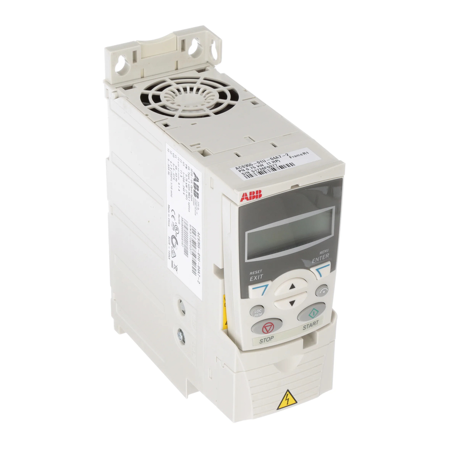
ACS355 Solar pump inverter. Solar pump inverter overview The ACS355 solar pump inverter is a low voltage AC drive of 0.3 to 18.5 KW rating designed to operate with energy drawn from photovoltaic cells (PV). The inverter is customized to operate in dual supply mode, so the grid connected supply is used in the absence of energy from PV cells. -
Page 16: Control Panels
• Assistant control panel—includes pre-programmed assistants to automate the most common parameter setups and provides language support. For more information, see section Control panels in ACS355 User’s manual (3AUA0000066143 [English]). Start-up procedure section for information on Viewing or Editing parameter values using control panel. -
Page 17: I-V Characteristics
Operating principle and hardware description 17 I-V characteristics Iact The I-V curve is not constant since intensity and temperature changes during day time. Under constant temperature, current changes linearly with intensity and voltage changes logarithmically with intensity. Since the voltage variation is small with respect to intensity changes, maximum power varies proportionally with intensity. - Page 18 18 Operating principle and hardware description...
-
Page 19: Quick Start-Up
This chapter includes the basic information about the mechanical and electrical installation of solar pump inverter and also provides steps to quickly operate the inverter. For general instructions on installation and maintenance of ACS355 Drives, see ACS355 User’s manual (3AUA0000066143 [English]). -
Page 20: Mechanical Installation
20 Quick start-up Mechanical installation In back mounting, fasten the inverter to the wall with screws using four mounting holes. In side mounting with frame sizes R0…R2, fasten the inverter to the wall with screws using three mounting holes. The inverter can also be mounted onto a DIN rail. Fasten the clamping plate to the plate at the bottom of the inverter with the provided screws. -
Page 21: Connection Procedure
Quick start-up 21 Connection procedure 1. Strip the input power cable. Ground the bare shield of the cable (if any) 360 degrees under the grounding clamp. Fasten the grounding conductor (PE) of the input power cable under the screw of the grounding clamp. Connect the phase conductors to the U1, V1 and W1 terminals. -
Page 22: Installing Control Cables
22 Quick start-up Installing control cables Default I/O connections Signal cable shield (screen) Not in use by default. 0…10 V Analog input circuit common +10V Reference voltage: +10 V DC, max. 10 mA Not in use by default. 0…10 V Analog input circuit common Max. -
Page 23: Connection Procedure
Quick start-up 23 Connection procedure 1. Remove the terminal cover by simultaneously pushing the recess and sliding the cover off the frame. 2. Strip the outer insulation of the analog signal cable and ground the bare shield 360 degrees under the clamp. -
Page 24: Operating Instructions
24 Quick start-up Operating instructions The solar pump inverter is developed using the ACS355 firmware. Install the inverter as defined in sections Mechanical installation, Installing power cables, and Installing control cables. Before operating the inverter, set the required parameters defined in the following steps. -
Page 25: Start-Up And Controls
This chapter describes the start-up operation of the solar pump inverter. Start-up procedure The start-up procedure to set up the solar pump inverter is similar to the ordinary ACS355 drive. See section Starting up the drive in ACS355 User’s manual (3AUA0000066143 [English]). - Page 26 26 Start-up and controls To select auto/manual mode in the control panel, follow these steps: Step Description Keys Control panel Press MENU to go to the main 0r p m R E M menu. 0.0 Hz 0.0 A 0.0 % 00:00 D I R ME N U...
-
Page 27: Viewing Pump Signals
Start-up and controls 27 Step Description Keys Control panel Press SAVE to store the PAR ED IT R E M modified value or press CANCEL to leave the set 6001 AUTO/MANUAL SEL mode. Any modifications not AUTO saved are cancelled. [ 0 ] C A N C E L 00:00... -
Page 28: Editing Pump Parameters
28 Start-up and controls Editing pump parameters The parameters 6001...6019 are user adjustable parameters to control the pump operation. The below steps explain the editing of inverter start voltage and inverter reset time. Similarly, edit the other pump parameters in this group. Step Description Keys... - Page 29 Start-up and controls 29 Step Description Keys Control panel Setting inverter reset time Select parameter 6019 PAR AM ETER S R E M FAULT RESET TIME with the 6016 MIN LOAD CURRENT UP/DOWN keys. Press EDIT 6017 DRY RUN TRP TIME to change the parameter 6018 DRY RUN RST TIME value.
- Page 30 30 Start-up and controls...
-
Page 31: Program Features
Program features 31 Program features About this chapter This chapter describes the pump control features of solar pump inverter. Each feature includes a list of related user settings, actual signals, and/or fault and alarm messages. Dry run function The solar pump inverter trips to a DRY RUN when the water flow is not available at the pump inlet or when a blockage occurs in the pump. -
Page 32: Boost Voltage Factor
DC voltage (6005 PV CELL MAX VOLT). Speed limits The ACS355 solar pump inverter operates within the defined speed limits set in the group 60 PUMP CONTROL parameters. • Minimum pump speed—Below this value, inverter stops the pump operation. The... -
Page 33: Settings
Program features 33 Settings Parameter Additional information 6006 PUMP MINIMUM SPD Minimum motor speed allowed. 6007 PUMP MAXIMUM SPD Maximum motor speed allowed. 2002 MAXIMUM SPEED Maximum speed limit. Flow calculation The flow calculation function provides a reasonably accurate calculation of the flow without the installation of a separate flow meter. -
Page 34: Settings
0185 CUMULA YEAR FLOW meter. PID control macro The ACS355 solar pump drive is designed to work with MPPT algorithm. Hence the PID control macro is disabled and similarly when the PID control macro is enabled, the MPPT algorithm is disabled. -
Page 35: Settings
6022 PMP CLEAN SPEED Speed at which the pump cleaning sequence is initiated. 6023 PMP CLEAN TIME Pump cleaning time. Excluded functions The following features of ACS355 firmware are not supported in the solar pump inverter. • Timer and counter • Frequency input •... - Page 36 36 Program features...
-
Page 37: Actual Signals And Parameters
This chapter describes the actual signals and user-adjustable parameters of the MPPT function specific to the solar pump inverter. Refer these parameters in addition to the actual signals and parameters described in the ACS355 User’s manual (3AUA0000066143 [English]). Actual signals... - Page 38 38 Actual signals and parameters Actual signals Name/Value Description FbEq 0185 CUMULA YEAR Shows the measured flow of current year in cubic 1 = 1 m FLOW decameter. The value displayed is the measured flow from first day to current day of the year. Note: You can reset this value using 6131 RESET FLOW.
- Page 39 No external fault 2. AI1_LOSS Analog input AI1 signal is below the limit defined in parameter 3021 AI1 FAULT LIMIT (See ACS355 User’s manual (3AUA0000066143 [English])). Analog input AI1 signal is within the limits defined in parameter 3021 AI1 FAULT LIMIT.
- Page 40 40 Actual signals and parameters Actual signals Name/Value Description FbEq Name Value Status SAFE_TORQUE_OFF STO (Safe torque off) is active. STO (Safe torque off) is not active. MOT_OVERTEMP Motor temperature estimation is beyond limit. Motor temperature estimation is within limit. START_ENABLE Start enable signal received.
-
Page 41: Parameters
Actual signals and parameters 41 Parameters All parameters Name/ Description Def/ FbEq Value 10 START/STOP/DIR Defines the sources for external start, stop and direction control. 1001 EXT1 Defines the connections and source for start, stop and SOLAR COMMANDS direction commands for external control location 1 (EXT1). - Page 42 0...1). The fieldbus controller sends the control word to the drive through the fieldbus adapter or embedded fieldbus (Modbus). For details of control word bits, see section DCU communication profile in ACS355 User’s manual (3AUA0000066143[English]). TIMED FUNC 1 Timed start/stop control. Timed function 1, Active = start and Inactive = stop.
- Page 43 Actual signals and parameters 43 All parameters Name/ Description Def/ FbEq Value Start and stop through digital input DI5. 0 = stop, 1 = start. Direction fixes based on parameter 1003 DIRECTION (REQUEST = FORWARD). DI5,4 Start and stop through digital input DI5. 0 = stop, 1 = start.
- Page 44 Fieldbus interface as the source for EXT1/EXT2 selection, that is Control word 0301 FB CMD WORD 1 bit 5 (with ABB drives profile 5319 EFB PAR 19 bit 11). The fieldbus controller sends the control word to inverter through fieldbus adapter or embedded fieldbus (Modbus).
- Page 45 • 1301 MINIMUM AI1 = 20% (2 V or 4 mA). • 3021 AI1 FAULT LIMIT = 5% or higher. • 3001 AI<MIN FUNCTION> = FAULT. For parameter details, see ACS355 User’s manual (3AUA0000066143[English]). AI2/JOYST See select AI1/JOYST.
- Page 46 COMM Fieldbus reference REF1. COMM+AI1 Summation of fieldbus reference REF1 and analog input AI. See section Reference selection and correction in ACS355 User’s manual (3AUA0000066143[English]). COMM*+AI1 Multiplication of fieldbus reference REF1 and analog input AI. See section Reference selection and correction in ACS355 User’s manual...
- Page 47 Actual signals and parameters 47 All parameters Name/ Description Def/ FbEq Value KEYPAD (RNC) Defines the control panel as reference source. The stop command resets the reference to zero (R represents reset). Note: The reference value is not saved if the control source is changed (EXT1 to EXT2 or EXT2 to EXT2).
- Page 48 Fieldbus interface as the source for the fault reset signal, that is the Control word 0301 FB CMD WORD 1 bit 4 (with ABB drives profile 5319 EFB PAR 19 bit 7) (see ACS355 User’s manual (3AUA0000066143 [English]). The Control word is sent by the fieldbus controller through the fieldbus adapter or embedded fieldbus (Modbus) to the drive.
- Page 49 (Modbus) to the drive. For the Control word bits, see section DCU communication profile in ACS355 User’s manual (3AUA0000066143 [English]). Note: This setting applies only for the DCU profile DI1(INV) Local lock through inverted digital input DI1.
- Page 50 DISABLE. EXTERNAL External brake chopper control. Note: • The drive is compatible only with ABB ACS-BRK-X brake units. • Ensure the brake unit is installed and the overvoltage control is switched off by setting parameter 2005 OVERVOLT CTRL to selection DISABLE.
- Page 51 • If acceleration time is set too short, the drive automatically prolongs the acceleration, not to exceed the drive operating limits. The actual acceleration time depends on parameter 2204 RAMP SHAPE 1 setting (see ACS355 User’s manual (3AUA0000066143 [English]). 0.0...1800.0 s Time 1 = 0.1 s...
- Page 52 Note: This parameter value is not recommended for permanent magnet synchronous motors. USER Custom ratio defined by parameters 2610…2618. See DEFINED section Custom U/f ratio in ACS355 User’s manual (3AUA0000066143 [English]). 2609 NOISE Enables the noise smoothing function. Noise ENABLE...
- Page 53 Can be used for permanent magnet synchronous motors only (see chapter Appendix: Permanent magnet synchronous motors (PMSMs) in ACS355 User’s manual (3AUA0000066143 [English])). Disabled ALWAYS Enabled always when the frequency is below the smooth start frequency (parameter 2623 SMOOTH STARTFRQ).
- Page 54 MODE. NOT SEL Protection is inactive. FAULT The drive trips on fault MOTOR STALL (0012) and the motor coasts to stop. See ACS355 User’s manual (3AUA0000066143 [English]). ALARM The drive generates alarm MOTOR STALL (2012). See ACS355 User’s manual (3AUA0000066143 [English]).
- Page 55 3601 TIMERS ENABLE, then the drive starts as per the timed function configuration. For more details of timed function, see group 36 TIMED FUNCTIONS in ACS355 User’s manual (3AUA0000066143 [English]). MANUAL Inverter starts when the manual start command is on.
- Page 56 56 Actual signals and parameters All parameters Name/ Description Def/ FbEq Value 6004 PV CELL MIN Defines the minimum DC voltage below which the 1 = 1 V VOLT inverter cannot operate. Note: The inverter stops operating below this voltage. 109...800 V DC voltage.
- Page 57 Actual signals and parameters 57 All parameters Name/ Description Def/ FbEq Value See selection DI1. See selection DI1. See selection DI1. DI1(INV) Inverted digital input DI1. Defines the inverted digital input DI1 as the control for dry run protection. DI2(INV) See selection DI1(INV).
- Page 58 58 Actual signals and parameters All parameters Name/ Description Def/ FbEq Value 6021 PMP CLEAN Enables the pump cleaning sequence for the inverter SELECT in the manual mode (see 6001 AUTO/MANUAL SEL) and defines the selection conditions. WARNING! Before enabling the pump cleaning sequence, make sure that it can be performed safely with the connected equipment.
- Page 59 Actual signals and parameters 59 All parameters Name/ Description Def/ FbEq Value 0...3276.0 kW Power 6102 PQ CURVE P2 Defines the input power of pump at point 2 on the PQ 10 = 1 kW curve. 0...3276.0 kW Power 6103 PQ CURVE P3 Defines the input power of pump at point 3 on the PQ 10 = 1 kW...
- Page 60 Note: All languages are not available for printing this manual because language list typically change as time passes. 9902 APPL MACRO Selects the application macros. See Application macros in ACS355 User’s manual (3AUA0000066143 STANDARD [English]). Standard macro for solar mode. STANDARD 3-WIRE 3-wire macro for constant speed applications.
- Page 61 All parameters Name/ Description Def/ FbEq Value AC500 AC500 PLC macro. See Modbus macro in ACS355 MODBUS User’s manual (3AUA0000066143 [English]). LOAD FD SET FlashDrop parameter values as defined by the FlashDrop file. For Parameter view, see 16 SYSTEM CONTROLS in ACS355 User’s manual (3AUA0000066143 [English]).
- Page 62 62 Actual signals and parameters All parameters Name/ Description Def/ FbEq Value 9904 MOTOR CTRL Selects the motor control modes. SCALAR: MODE FREQ WARNING! The VECTOR:TORQ motor control mode is not functional for solar mode. VECTOR: Vector control mode without sensor. SPEED Reference 1 = Reference speed in RPM Reference 2 = Reference speed in %.
- Page 63 Actual signals and parameters 63 All parameters Name/ Description Def/ FbEq Value 9905 MOTOR NOM Defines the motor nominal voltage. 1 = 1 V VOLT • For AM, nominal voltage is the value displayed on the motor name plate. • For PMSM, nominal voltage is back emf voltage at nominal speed.
- Page 64 • Parameter 9904 = 1 (VECTOR: SPEED): Identification magnetization is performed. • Parameter 9904 = 3 (SCALAR: FREQ): Identification magnetization is not performed. Note: The parameter 9904 = 2 (VECTOR: TORQ) is not functional in the ACS355 solar pump inverter.
- Page 65 Actual signals and parameters 65 All parameters Name/ Description Def/ FbEq Value ID run for control accuracy. The ID run takes about one minute. An ID run is effective when: • parameter 9904 = 1 [VECTOR: SPEED] is used • operation point is near zero speed Note: Ensure the following points: •...
- Page 66 66 Actual signals and parameters...
-
Page 67: Fault Tracing
Fault messages generated by the drive Alarm and fault indications A fault is indicated with a red LED. See section LEDs in ACS355 User’s manual (3AUA0000066143[English]). An alarm or fault message on the panel display indicates an abnormal inverter status. -
Page 68: How To Reset
FAULT 2 store the most recent faults. Parameters 0401...0409 show the inverter operation data at the time the latest fault occurred. The assistant control panel provides additional information about the fault history. For more information, see section Fault logger mode in ACS355 User’s manual (3AUA0000066143[English]). Fault messages The following faults messages are generated by the solar pump inverter. -
Page 69: Alarm Messages
Fault tracing 69 Alarm messages The following alarm messages are generated by the solar pump inverter. Code Fault Cause What to do 2036 PUMP MINIMUM This alarm occurs when the Check the pump minimum speed SPEED speed reference calculated by set in 6006 PUMP MINIMUM internal MPPT algorithm is less... - Page 70 70 Fault tracing...
-
Page 71: Technical Data
About this chapter This chapter contains the technical specifications of the solar pump inverter, for example: fuse ratings, sizes and technical requirements. It also includes the solar status word list. For technical specifications of ACS355 Drives, see ACS355 User’s manual (3AUA0000066143 [English]). -
Page 72: Inverter Power Rating
Inverter power rating Ratings for IP20 Type designation Frame size 1-phase AC supply, 125 to 400 V DC or 200 to 240 V 0.37 ACS355-01X-04A7-2 0.75 ACS355-01X-06A7-2 ACS355-01X-07A5-2 ACS355-01X-09A8-2 3-phase AC supply, 125 to 400 V DC or 200 to 240 V 0.37... -
Page 73: Fuse Ratings
Fuse ratings Use standard fuses with all ABB general machinery drives. For fuse ratings of ACS355 drives, refer the technical data on Power cable sizes and fuses in the ACS355 User’s manual (3AUA0000066143 [English]). For input fuse connection see fuse ratings in the table below. Refer to gG for AC and UR or gG for DC. - Page 74 74 Technical data Type code Frame size IEC Fuse AC side DC Fuse PV side Fuse [A] Fuse Type Type gG ACS355-03X-24A4-2 ACS355-03X-31A0-2 ACS355-03X-46A2-2 3-phase supply voltage 380 to 480 V units ACS355-03X-01A9-4 ACS355-03X-02A4-4 ACS355-03X-03A3-4 ACS355-03X-04A1-4 ACS355-03X-05A6-4 ACS355-03X-07A3-4 ACS355-03X-08A8-4 ACS355-03X-12A5-4...
-
Page 75: Ul Checklist
UL checklist • The ACS355 drive is an IP20 (UL open or NEMA 1 type) drive to be used in a heated, indoor controlled environment. The drive must be installed in clean air according to enclosure classification. Cooling air must be clean, free from corrosive materials and electrically conductive dust. - Page 76 76 Technical data...
-
Page 77: Further Information
Product and service inquiries Address any inquiries about the product to your local ABB representative, quoting the type designation and serial number of the unit in question. A listing of ABB sales, support and service contacts can be found by navigating to www.abb.com/searchchannels. - Page 78 Contact us www.abb.com/drives www.abb.com/solar www.abb.com/drivespartners 9ARD000864 Rev B (EN) 2015-02-02...
Need help?
Do you have a question about the ACS355 and is the answer not in the manual?
Questions and answers