Advertisement
Quick Links
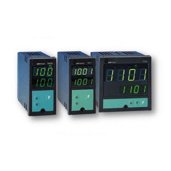
1 • INSTALLATION
• Dimensions and cut-out;
panel mounting
48
108 96
100
10
96
108 96
100
10
For correct and safe installation observe the warnings
!
contained in this manual
Panel mounting:
To fasten the instruments insert the block into the seats on the sides
of the box. To mount two or more instruments side by side respect the
dimensions swown above.
80343I_MHW_1000_07-2011_ENG
1000 / 1001 / 1101
CONFIGURABLE TEMPERATURE CONTROLLERS
70
92
44,5
115
92
92
INSTALLATION AND
OPERATION MANUAL
SOFTWARE VERSION 13.x
code 80343I / Edition 21 - 07-2011
2 • TECHNICAL SPECIFICATIONS
Display
Keys
Accuracy
Main input
(adjustable digital filter)
TC type(Thermocouples)
115
Cold junction error
RTD type
(scale configurable within
indi-cated range, with or
without decimal point)
Max. RTD line
resistanceRTD
115
Safety
°C / °F selection
DC - Linears
Control actions
pb - dt - it
2x3 digit green LEDs,
digit height 14-10-20mm
3 mechanical keys (Raise, Lower, F)
0.5% f.s. ±1 digit at 25° ambient
temperature
TC, RTD,
Sampling time 120 msec
for 1000
J (Fe-CuNi) 0...800°C / 32...999°F
K (NiCr-Ni) 0...999°C / 32...999°F
N (NiCr-Si-NiSi) 0...999°C / 32...999°F
S (Pt10Rh-Pt) 0...999°C / 32...999°F
R (Pt13Rh-Pt) 0...999°C / 32...999°F
T (Cu-CuNi)
-100...400°C / -148...752°F
for 1001, 1101
J (Fe-CuNi) 0...800°C / 32...999°F
K (NiCr-Ni) 0...1300°C / 32...1999°F
N (NiCr-Si-NiSi)
0...1300°C / 32...1999°F
S (Pt10Rh-Pt) 0...1600°C / 32...1999°F
R (Pt13Rh-Pt) 0...1600°C / 32...1999°F
T (Cu-CuNi)
-100...400°C / -148...752°F
Selection with faceplate keys.
0.05°C for each 1°C of variation
RTD 2/3 wires
for 1000
Pt100 -19.9...99.9°C / -19.9...99.9°F
Pt100 -199...400°C / -199...752°F
RTD 2/3 wires
for 1001, 1101
Pt100
-199.9...199.9°C / -199.9...199.9°F
Pt100
-200...400°C / -328...752°F
detection of short circuit or opening of
probes, LBA alarm, HB alarm
Faceplate configurable
0...50mV, 10...50mV
Input impedance > 1MΩ
For signals 0...10V, 0...20mA, 4...20mA
use only with dividers / shunt outside the
instrument.
Pid, Autotune, on-off
• Proportional band: 0.0...99.9% f.s.
• Integral time:
0.0...99.9 min
• Derivative time:
0.0...9.99 min (0.0...19.99 min)
• Reset power (positioning of proportional
band): 0...100%.
• Hysteresis (only for On/Off control):
-199...999 (-999...1999) digits.
Other specifications at page 2
1
Advertisement

Related Manuals for gefran 1000


Summary of Contents for gefran 1000
- Page 1 1000 / 1001 / 1101 CONFIGURABLE TEMPERATURE CONTROLLERS INSTALLATION AND OPERATION MANUAL SOFTWARE VERSION 13.x code 80343I / Edition 21 - 07-2011 1 • INSTALLATION 2 • TECHNICAL SPECIFICATIONS Display 2x3 digit green LEDs, • Dimensions and cut-out; digit height 14-10-20mm...
-
Page 2: Technical Specifications
Use a cloth dampened in ethyl alcohol or water to clean the external plastic parts. SERVICE: In GEFRAN è disponibile un reparto di assistenza tecnica. The warranty excludes defects caused by any use not conforming to these instructions. - Page 3 Value of variable controlled to 3 digits (1000) 3 digits (1001 -1101) Indication - 199...+999 (1000) indication -999...+1999 (1001-1101) with decimal point on appropriate scales. Positive (HI) or negative (LO) off-scale message Message for broken/incorrect connection of probe; (SBR: open circuit / ERR: probe reversed) and display of configuration and calibration messages.
-
Page 4: Hardware Configuration
4 • CONNECTIONS POWER NO / NC SERIAL SUPPLY LINE AL3/HB NO / NC MAIN (D2) Current input from TA 5Aac CONTINUOUS MAIN CONTROL OUTPUT Pt100 3 wires Pt100 2 wires 21 connections are available for 6.35 mm faston terminals. (N.C.);... - Page 5 6 • WORK MODE Sequence of phases in work mode Work phase Upper display Lower display Phase indication Notes Process variable Control setpoint* Note 1 Process variable Alarm limit 1 * Led AL1 flashing Note 2 Process variable Alarm limit 2 * Led AL2 flashing Note 2 Process variable...
- Page 6 If the control is ON/OFF (integral, derivative, and cycle time alarm limit, and is characteristic of a direct (or reverse) alarm. Hy2/: Hysteresis for AL2 in range -199.. +999 digit (1000) -19.9.. null), the set value defines hysteresis -199...+999 (1000) -19.9...+99.9 (1000 scale with decimal point) -999...+1999...
- Page 7 HB alarm and selection of temperature scale (°C or °F) Ct.A / AL1 Cycle time in range 0...200 sec. Set code for selected combination of functions as per the table. dt.A / AL1 Derivative time in range 0.00...9.99 min. (1000) Al.HB Scale 0.00...19.99 min (1001-1101).
- Page 8 7 • PROGRAMMING A.r.F/ Selection of alarm output function. set for ON time of MAIN output 1 - alarm trips when ammeter full scale (Hb.S) in main output Let you assign one of the following functions to each alarm output: Normal Alarm, HB Alarm, LBA Alarm, Alarm disabled OFF time is exceeded by 12%.
-
Page 9: Control Actions
8 • CALIBRATION Enable configuration and calibration as described in the The thermocouple and linear input is now calibrated. manual in the Hardware Configuration section (jumpers “S9” B) Calibration of Pt100 2/3 wires resistance thermometer and “S8” closed). In phase CFG/2 (Configuration 2) set the type of input probe: input (tyP =6 or 7). - Page 10 Absolute alarm: limit set with an absolute value compared to 0 The HB alarm function is selectable from 4 different modes by (Ex. for 1000: set-point = 400, AL1 = 450, AL2 = 350, AL3 = means of code Hb.F in phase CFG.2: 0 - alarm trips when load current drops below limit set for ON 500).
- Page 11 • ACCESSORIES • RS232 / TTL interface for GEFRAN instrument configuration Configuration software for Gefran products: Instruments, Drives; Sensors, Automation. Compatible with Windows 2000, XP, Vista. CD-ROM with selectable Italian/English language, with kit for PC-instrument serial port connection.
- Page 12 VAC. Resistors must be at least 2W); fit a 1N4007 diode in parallel with the coil of inductive loads that operate in DC GEFRAN spa will not be held liable for any injury to persons and/or damage to property deriving from tampering, from any incorrect or erroneous use, or from any use not conforming to the device specifications.
- Page 13 APPENDIX 1000 / 1001 / 1101 CONFIGURAZIONE HARDWARE CONFIGURATION MATÉRIELLE HARDWARE HARDWARE CONFIGURATION CONFIGURACIÓN HARDWARE HARDWARE-KONFIGURATION CONFIGURAÇÃO DO HARDWARE Per estrarre la parte elettronica dalla custodia agire sulla vite frontale fino allo sblocco, quindi estrarre manualmente. La configurazione si effettua sulle schede: ingresso_CPU, alimentazione_uscite e opzionali.
- Page 14 Scheda ingresso_CPU Sulla scheda sono posizionati i ponticelli per l’abilitazione/disabilitazione della configurazione e calibrazione come descritto nella seguente tabella: Descrizione Posizione ponticello jumper Ponticelli a stagno 45189x_lc / 45196x_lc (lato componenti) 45189x_ls / 45196x_ls (lato saldature) Configurazione abilitata S9 chiuso Configurazione disabilitata S9 aperto Calibrazione abilitata...
- Page 15 45189x_ls 45196x_ls Opzione allarmi 2 e 3 Selezione contatti NO/NC per relè di allarme 2 e 3. Normalmente gli allarmi 2 e 3 vengono forniti con contatti NO, per ottenere la versione NC é necessario rimuovere manualmente i rispettivi ponticelli NO ed effettuare quelli NC. Allarme 2 NC S1 (45189x_ls / 45196x_ls) Allarme 2 NO...
- Page 16 451901_ls Scheda alimentazione_uscite • Uscita principale D2 Quando si utilizza l’uscita D2 é consigliabile escludere l’attività del relè di MAIN togliendo manualmente il ponticello S1. • Uscita principale in continua V/I Per ottenere l’uscita in tensione effettuare il ponticello V, con il ponticello aperto l’uscita é in corrente. Output/power board •...
- Page 17 45195x_ls Scheda seriale current loop (cod 1 in sigla di ordinazione) Per collegamento parallelo (standard) chiudere S5 (S6 off). Per collegamento serie chiudere S6 (S5 off). S5 e S6 si trovano sul lato saldature della scheda 45195x_ls. Current loop serial board (code 1 in order code) Close S5 (S6 off) for parallel (standard connection).
- Page 18 45195x_ls Scheda seriale RS485 (cod 2 in sigla di ordinazione) La linea seriale RS485 può essere polarizzata eseguendo i ponticelli di stagno S1, S2 e S3 presenti sul lato saldature della scheda 45195x_ls. La distanza di trasmissione coperta dall’uscita seriale RS485 degli strumenti raggiunge i 500 metri con un massimo di 32 strumenti collegati. Per ulteriori informazioni consultare il manuale delle comunicazioni seriali codice 80034.
- Page 19 Gefran 1000, 1001, 1101: Installation Guide Tel: +27 11 966 9800 (JHB) +27 21 762 8995 (CT) sales@thermon.co.za www.unitemp.com/contact...
Need help?
Do you have a question about the 1000 and is the answer not in the manual?
Questions and answers
Je vous écris pour demander le logiciel GF_eXpress ainsi que les informations de raccordement pour le contrôleur de processus GEFRAN type 1000-R0-1R-0-1. Informations nécessaires : Logiciel GF_eXpress : Veuillez me fournir le lien de téléchargement et les instructions d'installation. Raccordement au PC : Je souhaiterais obtenir les détails des bornes de raccordement et les instructions pour connecter le contrôleur à un PC via le port RS485. Je vous remercie par avance pour votre aide et votre prompt retour. Cordialement,