Advertisement
CONTROLLER
cod. 80311 - 11/2012 - ENG
INSTALLATION AND OPERATION MANUAL
Side 1 1 Dimensions and cut-out; panel mounting
2 Installation and connection
3 Description of faceplate
4 Connections
Side 2 5 Technical specifications
6 "Easy" programming and configuration
The complete manual is available for download from the
website www.gefran.com
GEFRAN spa reserves the right to make any aesthetic or
functional change at any time and without notice.
Function indicators
Indicates modes of operation
MAN/AUTO =
OFF (automatic control)
ON (manual control)
SETPONT1/2 = OFF (IN1 = OFF - local Setpoint 1)
ON (IN1 = ON - local Setpoint 2)
SELFTUNING = ON (enabled Self)
OFF (disabled Self)
Automatic/Manual adjustment selection Active only when PV
display visualises the process variable
"Inc" and "Dec" key
Press to increment (decrement) any numerical parameter •• Increment (decrement) speed is proportional to time key stays
pressed •• The operation is not cyclic: once the maximum (minimum) value of a field is reached, the value will not change even if
the key remains pressed.
• Ammeter outputs/input
User configurable generic output
19
-
- 5A at 250Vac/30Vdc relay
- 24V, 10V at 20mA logic
Out2
20
- triac 20...240Vac, 1A ±10%
+
- Digital insulated 24Vac/dc
21
- 5A/250Vac relay only
Out1
22
- 5A at 250Vac/30vdc relay
- 24V, 10V at 20mA logic
-
6
- continuous 0...10V, 0/4...20mA
- analog 0...10V, 0/4...20mA for
Out3 (Al2)
transmission, resolution 12 bit
Ing. T.A.
- input from current transformer
5
+
50mAac, 10 Ω 50/60 Hz
- logic input 24V, 5mA or from
no-voltage contact
- Digital insulated 24Vac/dc
• Power Supply
Standard:
100...240Vac ±10%
~
23
Optional:
PWR
11...27Vac/dc ±10%
Max. power 10VA; 50/60Hz
~
24
• Serial line / output 4
Modbus
Cencal
Out 4
A
9
9
-
5A at
(Data +)
250Vac/30Vdc
TX
10
10
relay
B
+
(Data -)
11
11
11
-
RX
Standard
12
+
12
configuration
RS485 isolated serial line
See serial card data sheet for Cencal configuration
• Device structure
SERIAL INTERFACE/OUT4
CPU
POWER
DISPLAY
600
1 • DIMENSIONS AND CUT-OUT;
PANEL MOUNTING
63
48
48
45
99
10
For correct and safe installation,
follow the instructions and
observe the warnings contained
in this manual.
Panel mounting:
To fix the unit, insert the brackets provided into the seats on either
side of the case.
To mount two or more units side by side, respect the cut-out
dimensions shown in the drawing.
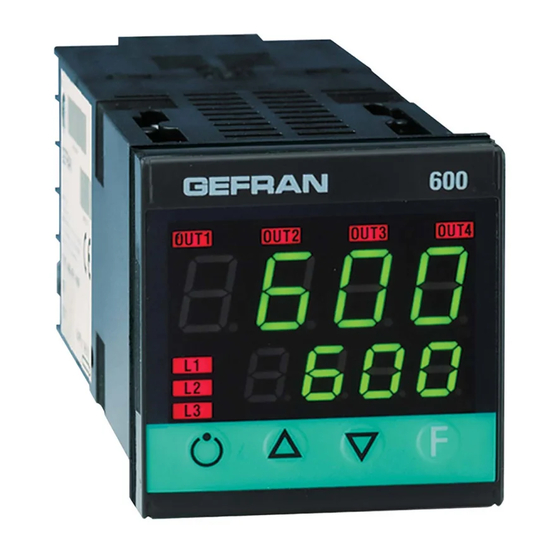
3 • DESCRIPTION OF FACEPLATE
ouT1
ouT2
8 8 8 8
L1
8 8 8 8
L2
L3
4 • CONNECTIONS
TOP
19
18
7
20
17
8
21
16
9
22
15
10
23
14
11
24
13
12
Linear input
in dc current
Ri = 50Ω
Linear input in
dc voltage
60mV, 1V Ri > 1MΩ
5V, 10V Ri > 10KΩ
Power board - Solder side
Select transmitter
voltage
CPU board - Component side
2 • INSTALLATION AND CONNECTION
This section contains the instructions necessary for correct
installation of the 600 controllers into the machine control
70
panel or the host system and for correct connection of the
controller power supply, inputs, outputs and interfaces.
Before proceeding with installation read the following
70
warnings carefully!
Remember that lack of observation of these warnings
could lead to problems of electrical safety and
electromagnetic compatibility, as well as invalidating
45
the warranty.
Electrical power supply
• the controller is NOT equipped with an On/Off switch: the user
must provide a two-phase disconnecting switch that conforms to
the required safety standard (CE marking), to cut off the power
supply upstream of the controller.
The switch must be located in the immediate vicinity of the
controller and must be within easy reach of the operator. One
switch may control more than one controller.
• if the controller is connected to NOT isolated electrical equipment
(e.g. thermocouples), the earth connection must be made with a
specific conductor to prevent the connection itself from coming
directly through the machine structure.
Indication of output states
600
OUT 1 (AL1); OUT 2 (Main); OUT 3 (HB); OUT 4 (HB)
ouT3
ouT4
PV Display: Indication of process variable
Error Indication: LO, HI, Sbr, Err
LO = the value of process variable is < di LO_S
PV
HI = the value of process variable is > di HI_S
Sbr = faulty sensor or input values higher than max. limits
Err = PT100 third wire opened for PT100, PTC or input
values lower than min. limits (i.e.: TC wrong connection)
SV
F
SV display: Indication of setpoint
Function key
Gives access to the various configuration phases ••
Confirms change of set parameters and browses next or
previous parameter (if Auto/Man key is pressed)
6
Available thermocouples:
5
J, K, R, S, T
(B, E, N, L, U, G, D, C custom linearization
is available)
4
- Observe polarities
- For extensions, use the correct
compensating cable for the type of TC used
3
• Linear input with 3-wire transmitter
Connect at 20mA input
2
4
VT
+ 24V o 15V
1
3
-
2
+
1
• Linear input (I)
• Input 1 linear with transmitter 2 wires
-
4
2
20mA,
+
1
• Linear input (V)
Use wires of
2
-
adequate diameter
(min. 1mm
)
2
PT100, JPT100,
PTC, NTC
1
+
• Identification of boards
R20
S2
NB.: you can keep the OUT1 relay energized at power-up by
inserting jumper S2 and removing resistance R20.
• if the controller is used in applications with risk of damage to
persons, machinery or materials, it is essential to connect it up
to auxiliary alarm equipment. It is advisable to make sure that
alarm signals are also triggered during normal operation.
The controller must NOT be installed in flammable or explosive
environments; it may be connected to equipment operating
in such atmospheres only by means of appropriate and
adequate types of interface, conforming to the applicable safety
standards.
Notes Concerning Electrical Safety and
Electromagnetic Compatibility:
CE MARKING:
The instrument conforms to the European Directives 2004/108/
CE and 2006/95/CE with reference to the generic standards:
EN 61000-6-2 (immunity in industrial environment) EN 61000-6-3
(emission in residential environment) EN 61010-1 (safety).
Series 600 temperature controllers are mainly designed to
operate in industrial environments, installed on the switchboards
or control panels of productive process machines or plants.
Instrument power supply
• The power supply to the electronic equipment on the
switchboards must always come directly from an isolation
device with a fuse for the instrument part.
• The electronic instruments and electromechanical power
devices such as relays, contactors, solenoid valves, etc., must
always be powered by separate lines.
• When the electronic instrument power supply is strongly
disturbed by the commutation of transistor or power units
or motors, an isolation transformer should be used for the
controllers only, earthing the screen.
• It is essential that the plant has a good earth connection:
- the voltage between neutral and earth must not be >1V
- the Ohmic resistance must be <6W;
• If the mains voltage fluctuates strongly, use a voltage stabilizer.
• In the proximity of high frequency generators or arc welders,
use adequate mains filters.
• The power supply lines must be separate from the instrument
input and output ones.
Inputs and outputs connection
• The externally connected circuits must be doubly isolated.
• To connect the analogue inputs (TC, RTD) the following is
necessary:
- physically separate the input cables from those of the power
supply, the outputs and the power connections.
- use woven and screened cables, with the screen earthed in
• Inputs
one point only
• TC Input
• To connect the regulating and alarm outputs (contactors,
-
solenoid valves, motors, fans, etc.), fit RC groups (resistance
2
and condensers in series) in parallel to the inductive loads that
operate in Alternating Current.
(Note: all the condensers must conform to VDE (class X2)
standards and withstand a voltage of at least 220V AC. The
1
resistances must be at least 2W).
+
• Fit a 1N4007 diode in parallel with the coil of this can be
removed inductive loads that operate in Direct Current.
+
S
-
Warnings and instructions for mounting to the panel
4
• only for low power supply: supply from Class 2 or low voltage
+
VT
24V o 15V
3
+
limited energy source.
• the power supply lines must be separate from the controller
-
-
2
input and output ones
• group the instruments together keeping them separate from the
+
4...20mA
1
powered part of the relay
• do not install high-power remote switches, contactors, relays,
• Pt100 / PTC / NTC
thyristor power units (especially the "phase angle" type),
motors, etc. in the same switchboard
3
• avoid dust, humidity, corrosive gasses and heat sources
• do not block the ventilation holes: the working temperature
2
must be between 0...50°C
T
T
• surrounding air: 50°C
1
• use 60/75°C copper (Cu) conductor only, wire size range 2x No
PTC / NTC
Pt100 3 wires
/ Pt100 2 wires
22 - 14AWG, Solid/Stranded
• use terminal tightening torque 0.5N m
Nominal ambient conditions
Altitude
Working/storage
temperature
Non condensing
relative humidity
IN/OUT boards
(see appendix)
Select signal at
contact 3
GEFRAN spa via Sebina, 74 - 25050 Provaglio d'Iseo (BS)
Tel. 03098881 - fax 0309839063 Internet: http://www.gefran.com
Advice for Correct Installation for EMC
GEFRAN S.p.A. declines all responsibility for any
damage to persons or property caused by tampering,
neglect, improper use or any use which does not
conform to the characteristics of the controller and to
the indica tions given in these Instructions for Use.
Instructions for installation category II, pollution
level 2, double isolation.
Up to 2000m
0..50°C/-20...70°C
20...85%
Before supplying the Controller with power, make
sure that the mains voltage is the same as that
shown in the last number of the order code.
Advertisement
Table of Contents

Related Manuals for gefran 600


Summary of Contents for gefran 600
- Page 1 This section contains the instructions necessary for correct The controller must NOT be installed in flammable or explosive installation of the 600 controllers into the machine control environments; it may be connected to equipment operating panel or the host system and for correct connection of the in such atmospheres only by means of appropriate and controller power supply, inputs, outputs and interfaces.
- Page 2 5 • TECHNICAL SPECIFICATIONS 6 • “EASY” PROGRAMMING and CONFIGURATION S4 Jumper THE EASY CONFIGURATION IS SUITABLE FOR VERSIONS This section contains a list of the Technical Specifications for the 600 Controller. (CPU) Custom menu WITH TWO OUTPUTS (OUT1, OUT2). TO ACCESS THE OTHER PARAMETERS, ADD 128 TO THE Pro VALUE. Display 2x4 digits, green, height 10 and 7mm Input settings Keys 4 mechanical keys (Man/Auto, INC, DEC, F) LEVEL 1 MENU Accuracy 0.2% f.s. ±1 at 25°C room temperature Thermal drift 0.005% f.s. / °C Output settings P.V. / S.V. P.V. / S.V. Process variable (PV display) Main input (configurable digital filter) TC, RTD, PTC, NTC 60mV,1V Ri≥1MW; 5V,10V Ri≥10KW; 20mA Ri=50W Work Setpoint (SV display) or Sampling time 120 msec. control output value with controller...
Need help?
Do you have a question about the 600 and is the answer not in the manual?
Questions and answers